20
User’s Guide EN

User’s GuideEN

2 | DISPENSMANTM
TABLE OF CONTENTS
GENERAL PRODUCT DESCRIPTION | 3Description | 3
Parts Checklist | 5
SAFETY & USER PRECAUTIONS | 6General Safety Precautions | 6
Safety Considerations Before Initial Operation | 7
Operating Limitations | 7
Liquids Contact Material | 7
INSTALLATION | 8Telescopic Tube | 8
Bottle Adapter | 8
OPERATION | 9Volume adjustment | 9
Air Purging | 9
Dispensing | 10
Anti-Drop system | 10
MAINTENANCE | 11Disassembly | 11
Assembly | 11
CLEANING AND STERILIZATION | 12Cleaning | 12
Sterilization | 12
CALIBRATON | 13
TROUBLESHOOTING | 14
SPECIFICATIONS | 15
SPARE PARTS | 16Spare Parts for Small Volumes (2.5, 5, and 10 mL) | 16
Spare Parts for Large Volumes (25 and 50 mL) | 16
APPENDIX | 17
WARRANTY | 18
TAB
LE O
F C
ON
TEN
TS

GE
NE
RA
L PR
OD
UC
T DE
SCR
IPTIO
N
3DISPENSMANTM | USER’S GUIDE
Chapter 1
GENERAL PRODUCT DESCRIPTION
DISPENSMAN™ is a sophisticated dispensing system that fulfills increasing requirements for quality, precision, and reproducibility in laboratories. It consists of high precision components and extremely robust materials. It has a built-in recalibration mechanism that ensures reproducibility for the life of the instrument.
DISPENSMAN is an exclusive instrument with 0% loss of reagent due to air-purging and draining within a closed circuit. The valve block can rotate 360°; therefore, the label of the bottle is always visible for your added safety. The dispenser has our unique 100% drip-free system for your safety at work: just turn the nozzle switch to “Empty” (180°) to drain it and prevent uncontrolled flow of liquid.
The dispenser is fully autoclavable at 121°C and can be completely disassembled for cleaning. Each instrument is individually tested and delivered with a certificate of performance.
Description1
2
3
4
56
87
9
20
10
11
Safety capRecalibration mechanismOuter housingQuick-lock knobAdaptor ringCap nutNozzle switchProtective sleeveDischarge tubeNozzle setBottle adaptorValve block
123456789101120

GE
NE
RA
L P
RO
DU
CT
DE
SCR
IPTI
ON
4 GENERAL PRODUCT DESCRIPTION | DISPENSMANTM
IMPORTANT: Edges on top!
Adaptor ringCap nutNozzle switchSuction valveValve starValve ballEjection valveO-ring
PistonCylinder set Cylinder Valve blockTelescopic tubeReflux tube
19
56
1520
7
22
21
12
567
202122
12
7
16
14
13
17
18
191817
1615141312
Figure 1Nozzle switch and its axle, located inside the valve block
Figure 2Valve block without nozzle
Figure 3Valve block, top view
Figure 4Aspiration system, located under outer housing
Figure 5Valve block, bottom view

GE
NE
RA
L PR
OD
UC
T DE
SCR
IPTIO
N
5DISPENSMANTM | USER’S GUIDE
Parts ChecklistAfter unpacking the DISPENSMAN, verify that the following items were included and not damaged:
• 1GilsonDISPENSMANwithanattachedrefluxtube• 1telescopictube• 1protectivesleevewithanattacheddischargetube• 1calibrationtool• 4adaptorswithdifferentdiameters(mm):
• For small volumes (2.5, 5, 10 mL): A25, A28, A40, A45• For large volumes (25, 50 mL): A25, A28, A40, A32
• 1certificateofperformance• 1user’sguide
PistonCylinder set Cylinder Valve blockTelescopic tubeReflux tube

SAF
ET
Y &
US
ER
PR
EC
AU
TIO
NS
6 SAFETY & USER PRECAUTIONS | DISPENSMANTM
Chapter 2
SAFETY & USER PRECAUTIONS
General Safety PrecautionsIn order to put the instrument into operation as quickly as possible and free from defects, it is necessary that you read this manual carefully before using this instrument.
Highest safety precautions should be used when dispensing corrosive, poisonous, radioactive, or hazardous chemicals.
• Observe the general safety regulations for handling chemicals (e.g., protective clothing, protective goggles).
• Use DISPENSMAN only with regard to the chemical resistance of materials and for the purpose for which is intended (see the chemical compatibility list, pages 17 and 18).
• Always check the instrument for leak tightness and a firm position of the plug and socket connection before you use it.
• Never use force. Breakage of any part will lead to hazardous exposure for the user as well as for other persons.
• Clean the instrument every week and if you want to use DISPENSMAN for another chemical solution or if you do not use it for a longer time.
• The temperature of the dispenser and reagent should not exceed 40°C (104°F).
• The user is responsible for checking that the instrument is suitable for his application.
• The proper and secure function is only guaranteed by using the supplied discharge tube 9 . Do not use any other discharge tube.
• Never use damaged or deformed tubes. If the valve is damaged, the discharge tube might drop.
• The discharge tube should never face the user and a collection vessel should be placed underneath.
• Check all fittings for tightness approximately one hour after assembly or disassembly as temperature variations may cause material expansion, which can cause leakages.
• If you are unsure about dispensing a specific chemical solution, refer to the chemical compatibility list in pages 17 and 18 or contact your local Gilson representative.

SAF
ET
Y &
US
ER
PR
EC
AU
TION
S
7DISPENSMANTM | USER’S GUIDE
OPERATION LIMIT MAXIMUM
Vapor pressure 600 mbar
Viscosity 500 mm2/s
Density 2.2 g/cm3
Temperature <+15°C and >+40°C<+59°F and >+104°F
Safety Considerations Before Initial Operation• Check instrument for damage caused in transit.
• The telescopic tube 21 should reach the bottom of the bottle.
• Do not use the outer housing 3 for carrying the assembled dispenser. If you need to carry the instrument, hold it by the base of the instrument.
• Attach discharge tube 9 and clip on protective sleeve 8 carefully to avoid damage.
• Whenscrewingon/offthebottledonotholdtheinstrumentatitsouterhousing 3 , but at the screw base.
• Do not pump before the instrument has been assembled completely and a collecting vessel has been placed underneath.
Operating LimitationsDo not use for:• PTFE swelling solvents• Hydrofluoric acid• Chemical solutions that react with platinum-iridium alloys
Liquids used with DISPENSMAN must not exceed the following limits:
Liquid Contact MaterialsThe components having direct contact with the reagent are made of chemical resistant materials: platinum spring, ceramic valve balls, PTFE piston, and borosilicate glass 3.3 cylinder.

INS
TALL
ATI
ON
8 INSTALLATION | DISPENSMANTM
Chapter 3
INSTALLATION
Telescopic TubePress gently the telescopic tube 21 into the smaller hole of the bottom part of the valve block. Check for the proper length of the telescopic tube (it should reach the bottom of the bottle).
The reflux tube 22 is already attached to the bigger hole.
Bottle Adaptor
Choose the right adaptor according to your bottle. Screw the chosen adaptor on to the extremity of the bottle and screw DISPENSMAN into the adaptor. Check the stability of the instrument on the bottle before operating.
21
22
Figure 6Valve block, bottom view

OP
ER
ATIO
N
9DISPENSMANTM | USER’S GUIDE
Chapter 4
OPERATION
Legend of arrows in pictures:
ARROW SIGNIFICATION
User action on the instrument
Liquid movement into the instrument
Recycle(90°)
4
Volume AdjustmentThe quick-volume adjustment is performed with the quick-lock knob 4 . Push the quick-lock knob, slide it down to the desired volume, and then release.
Air PurgingTurn the nozzle switch 7 to “Recycle” (90°). Set a small volume and dispense until the cylinder 19 is free from air. Air-purging is performed in a closed circuit for zero loss of reagent.
Turn the discharge tube back to “Dispense” (0°). Adjust to the desired volume. Dispense liquid precisely and carefully until the end of discharge tube 9 is fully filled. Without any air in the entire instrument, this step will guarantee that the dispensed volume is precise (zero point). Then, fill the cylinder up to the selected volume.
The DISPENSMAN is now ready to dispense the desired volume.
7

OP
ER
ATI
ON
10 OPERATION | DISPENSMANTM
Dispensing
To avoid personal injury from chemicals, wear eye protection and protective clothing and use appropriate safety equipment. Follow safety and operation instructions in this manual.
Raise the outer housing until it reaches a hard stop at the set volume. The set volume will be dispensed into the collecting vessel by pressing down the outer housing to the lowest point. The movements should be smooth and constant to achieve an accurate dispense volume.
Noise while aspirating or dispensing is acceptable as it is because of the high quality suction valve with valve ball.
Anti-Drop SystemTurn the nozzle switch 7 to “Empty” (180°). The liquid from the discharge tube will now rinse back into the bottle. Any further dispensing of liquid is not possible in this position.
Turn the nozzle switch 7 to “Recycle” (90°) to seal the dispenser.
Dispense (0°)
Empty (180°)
3
3
7
MA
INT
EN
AN
CE
11DISPENSMANTM | USER’S GUIDE
Chapter 5
MAINTENANCE
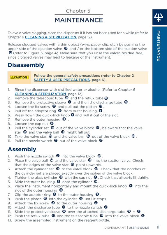
To avoid valve clogging, clean the dispenser if it has not been used for a while (refer to Chapter 6 CLEANING & STERILIZATION, page 12).
Release clogged valves with a thin object (wire, paper clip, etc.) by pushing the upper side of the ejection valve 15 and / or the bottom side of the suction valve 12 (refer to Figure 3, page 4). Make sure that you rinse the valves residue-free,
since clogged valves may lead to leakage of the instrument.
Disassembly
Follow the general safety precautions (refer to Chapter 2 SAFETY & USER PRECAUTIONS, page 6).
1. Rinse the dispenser with distilled water or alcohol (Refer to Chapter 6 CLEANING & STERILIZATION, page 12).
2. Remove the telescopic tube 21 and the reflux tube 22 .3. Remove the protective sleeve 8 and then the discharge tube 9 .4. Loosen the fix screw 2 and pull out the piston 17 .5. Pullofftheadaptorring 5 from outer housing 3 .6. Press down the quick-lock knob 4 and pull it out of the slot. 7. Remove the outer housing 3 .8. Loosen the cap nut 6 .9. Pull the cylinder set 18 out of the valve block 20 , be aware that the valve
star 13 and the valve ball 14 might fall out.10. Take the valve star 13 and the valve ball 14 out of the valve block 20 .11. Pull the nozzle switch 7 out of the valve block 20 .
Assembly1. Push the nozzle switch 7 into the valve block 20 .2. Place the valve ball 14 and the valve star 13 into the suction valve. Check
that the edges of the valve star 13 point upwards.3. Attach the cylinder set 18 to the valve block 20 . Check that the notches of
the cylinder set are placed exactly over the spikes of the valve block.4. Tighten the glass cylinder 19 with the cap nut 6 . Check that all parts fit tightly.5. Slide the outer housing 3 onto the cylinder 19 .6. Place the instrument horizontally and mount the quick-lock knob 4 into the
slot of the outer housing 3 .7. Clip the adaptor ring 5 to the outer housing 3 .8. Push the piston 17 into the cylinder 19 until it stops.9. Attach the fix screw 2 to the outer housing 3 .10. Attach the discharge tube 9 to the nozzle switch 7 .11. Slide the protective sleeve 8 over the attached discharge tube 9 + 7 .12. Push the reflux tube 22 and the telescopic tube 21 into the valve block 20 .13. Screw the assembled instrument on the reagent bottle.

CLE
AN
ING
& S
TE
RIL
IZA
TIO
N
12 CLEANING & STERILIZATION | DISPENSMANTM
Chapter 6
CLEANING & STERILIZATION
CleaningCleaning is necessary if you want to use the dispenser for another chemical solution or if has not been used for a long time. During cleaning, please follow the safety instructions (refer to Chapter 2 SAFETY & USER PRECAUTIONS, page 6).
Before cleaning, remove all liquid from the dispenser without any loss of reagent by following these steps:1. Turn the nozzle switch to “Empty” (180°) and let the remaining reagent from
the discharge tube flow back into the reagent bottle.2. Unscrew the dispenser from the bottle. 3. Drain the telescopic tube 21 by slightly tapping inside the reagent bottle. 4. Turn the nozzle switch from ”Empty” (180°) to “Recycle” (90°) and remove all
remaining liquid from the cylinder back into the reagent bottle.
For cleaning, follow these steps:1. Attach the telescopic tube and then screw the dispenser on a bottle with
distilled water or alcohol.2. Turn the nozzle switch to “Dispense” (0°). 3. Dispense multiple times until the instrument is clean.
If necessary, disassemble the dispenser (Chapter 5 MAINTENANCE, on page 11) and clean all components.
The dispenser should be cleaned daily if used with following chemicals:• Solutions that tend to crystallize (e.g., salts)• Inorganic oxidizing solutions (e.g., biuret reagent)
SterilizationAfter removal of the reflux tube 22 and the telescopic tube 21 , the dispenser can be steam-sterilized (121°C, 1 bar, 20 minutes) according to EN ISO 17665. Place the instrument on a cloth and avoid any contact with hot, metal surfaces.The discharge tube 9 has to be attached to the protective sleeve 8 .
Inordertopreventlossofadjustmentduetoheatexpansionofthedifferentmaterials, the quick-lock knob 4 has to be set to a minimum of 2/10 of its maximum volume. Before you use the dispenser, let it reach room temperature (about 2 hours cooling time). After autoclaving, check all screw fittings for tightness and the calibration of the instrument. Recalibrate the dispenser, if necessary (refer to Chapter 7 CALIBRATION, page 13). After autoclaving, perform a visual check of the instrument for any changes and verify all screw fittings.
In case of deformation, please return the instrument with a description of the autoclave protocols that were used.

CA
LIBR
ATIO
N
13DISPENSMANTM | USER’S GUIDE
Chapter 7
CALIBRATION
DISPENSMANTM is calibrated according to EN ISO 8655-5:2002 and EN ISO 8655-6:2002. After assembling the instrument, calibrate it per the instructions below:
1. Remove the safety cap 1 . The built-in recalibration mechanism is now visible (Figure 7).
2. Attach the calibration tool or standard hex key to the safety bolt (Figure 8).3. Use the calibration tool or hex key to pull out the safety bolt. 4. Attach the calibration tool with the thicker side to the site of the safety bolt
(Figure 9).5. To recalibrate a volume set too low, rotate the calibration tool clockwise. To
recalibrate a volume set too high, rotate the calibration tool counter-clockwise.6. Attach the safety bolt to the piston (Figure 8).7. Check the volume. If the measured volume exceeds the tolerance limits, then
calibrate the instrument again. If the calibration was successful, attach the safety cap (Figure 10).
Calibration tool
Safety capSafety bolt Fix screw Piston
Figure 7Built-in recalibration mechanism
Figure 8Use of calibration tool
Figure 9Thin side of safety bolt
Figure 10Put back the safety cap
Figure 11Calibration system, from the top of DISPENSMAN to inside, under outer housing

TR
OU
BLE
SH
OO
TIN
G
14 TROUBLESHOOTING | DISPENSMANTM
Chapter 8
TROUBLESHOOTING
Valve SticksWith the dispensing unit screwed on, ensure that the valves are surrounded by liquid and that the valve system is easy to move by rinsing it with distilled water and/or laboratory cleaning agent. As a last step, rinse with alcohol.
Piston Difficult to MoveCheck whether crystals have formed, and if so, carry out intensive cleaning of the piston and the cylinder (refer to Chapter 5 MAINTENANCE, page 11).
No Liquid Dispensed • Check that the nozzle switch is set to “Dispense” (0°).• Check the suction valve and then clean it, if necessary. • Check the nozzle switch. If it is not clean and operational, clean unit by
immersing nozzle set in cleaning fluid.• Check the discharge tube. If it is not clean and operational, disassemble it,
and then flush it with cleaning fluid.
No Liquid Aspirated• Check the fit of the telescopic tube into the suction valve. It should be firmly
pressed into the outer housing.• Check the volume setting.• Check the suction valve and then clean it, if necessary.
Air Bubbles in Aspirated Liquid• Check whether all air has been removed from the instrument, (See Chapter 4
OPERATION, page 9). • Check that the reservoir is not empty. • Check the telescopic tube, if necessary slide it to shorten it or replace it in its
socket.• Ensure slow, steady aspiration of reagent.• Check the suction valve and then clean it, if necessary.
Incorrect Volume DispensedCalibrate the instrument (See Chapter 7 CALIBRATION, page 13).

TR
OU
BLE
SH
OO
TING
15DISPENSMANTM | USER’S GUIDE
If any problem persists, please return DISPENSMAN back to your local Gilson service center.
Return for Repair
Please clean the instrument carefully, as described in Chapter 6 CLEANING & STERILIZATION, page 12. Never send in instruments filled with reagents. Returned instruments can only be checked and repaired if they have been carefully cleaned and decontaminated by the customer.
Forced opening of the instrument invalidates any warranty claim. Enclose with the returned instrument a description of the trouble that has occurred and specify which reagents were used.
Chapter 9
SPECIFICATIONS
DISPENSMANisahighqualitydispenserthatoffersexcellentaccuracyandprecision; it is fully compliant with ISO 8655. Each dispenser is inspected and validated by qualified technicians. Gilson declares that its manufactured dispensers comply with the requirements of the ISO 8655 standard, by type testing. The adjustment is carried out under strictly defined and monitored conditions.
MODEL PART NUMBER VOLUME RANGE SCALING
(mL)
MAXIMUM PERMISSIBLE ERRORS
GILSON ISO 8655-5
SYSTEMATIC ERROR (mL)
RANDOM ERROR (mL)
SYSTEMATIC ERROR (mL)
RANDOM ERROR (mL)
DISPENSMAN 2.5 mL F110101 0.25 – 2.5 mL 0.05 ±0.012 ≤ 0.002 ±0.030 ≤ 0.010
DISPENSMAN 5.0 mL F110102 0.5 – 5 mL 0.10 ±0.030 ≤ 0.005 ±0.030 ≤ 0.010
DISPENSMAN 10 mL F110103 1 – 10 mL 0.20 ±0.060 ≤ 0.010 ±0.060 ≤ 0.020
DISPENSMAN 25 mL F110104 2.5 – 25 mL 0.50 ±0.150 ≤ 0.025 ±0.150 ≤ 0.050
DISPENSMAN 50 mL F110105 5 – 50 mL 1.00 ±0.300 ≤ 0.050 ±0.300 ≤ 0.100
NOTICE
Noise During Aspiration and DispensingNoise while aspirating or dispensing is acceptable as it is because of the high quality suction valve with valve ball.
SPE
CIFIC
ATIO
NS

SPA
RE
PA
RT
S
16 SPARE PARTS | DISPENSMANTM
DESCRIPTION PART NUMBER
Calibration tool F107122
8 + 9Discharge tube with protective
sleeve made of FEP/PP for 2.5 mL F107124
8 + 9Discharge tube with protective
sleeve made of FEP/PP for 5 and 10 mL F107125
22 Reflux tube, 40mm, l.Ø:3mm, A.Ø: 4 mm F107127
21 Telescopic tube, 125 – 240 mm F107133
21 Telescopic tube, 250 – 480 mm F107135
21 Telescopic tube, 70 – 140 mm F107136
21 Telescopic tube, 195 – 350 mm F107137
11 Thread adapters made of PP invert GL A45/A32 F107139
11 Thread adapters made of PP GL A32/A45 F107140
11 Thread adapters made of PP GL A32/A40 F107141
11 Thread adapters made of PP GL A32/A38 F107142
11 Thread adapters made of PP GL A32/A28 F107143
11 Thread adapters made of PP GL A32/A25 F107144
Chapter 10
SPARE PARTSSpare Parts for Small Volumes (2.5, 5, and 10 mL)
Spare Parts for Large Volumes (25 and 50 mL)DESCRIPTION PART NUMBER
Calibration tool F107123
8 + 9Discharge tube with protective sleeve
made of FEP/PP for 25 and 50 mL F107126
22 Reflux tube, 40mm, l.Ø:6mm, A.Ø: 7 mm F107128
21 Telescopic tube, 170 – 330 mm F107134
21 Telescopic tube, 250 – 480 mm F107138
11 Thread adapters made of PP invert GL A45/A32 F107139
11 Thread adapters made of PP GL A32/A45 F107140
11 Thread adapters made of PP GL A32/A40 F107141
11 Thread adapters made of PP GL A32/A38 F107142
11 Thread adapters made of PP GL A32/A28 F107143
11 Thread adapters made of PP GL A32/A25 F107144

AP
PE
ND
IX
17DISPENSMANTM | USER’S GUIDE
DESCRIPTION PART NUMBER
Calibration tool F107122
8 + 9Discharge tube with protective
sleeve made of FEP/PP for 2.5 mL F107124
8 + 9Discharge tube with protective
sleeve made of FEP/PP for 5 and 10 mL F107125
22 Reflux tube, 40mm, l.Ø:3mm, A.Ø: 4 mm F107127
21 Telescopic tube, 125 – 240 mm F107133
21 Telescopic tube, 250 – 480 mm F107135
21 Telescopic tube, 70 – 140 mm F107136
21 Telescopic tube, 195 – 350 mm F107137
11 Thread adapters made of PP invert GL A45/A32 F107139
11 Thread adapters made of PP GL A32/A45 F107140
11 Thread adapters made of PP GL A32/A40 F107141
11 Thread adapters made of PP GL A32/A38 F107142
11 Thread adapters made of PP GL A32/A28 F107143
11 Thread adapters made of PP GL A32/A25 F107144
Chapter 11
APPENDIXChemical Compatibility
Acetaldehyde Butyric acid Glycol
Acetic acid 100% Calcium carbonate Glycolic acid 50%
Acetic acid 96% Calcium chloride Hexanoic acid
Acetone Calcium hydroxide Hexanol
Acetonitrile Calcium hypochlorite Hydriodic acid 57%
Acetylacetone Chloro naphthalene Hydrochloric acid 20%
Acrylic acid Chloroacetaldehyde 45% Isoamyl alcohol
Acrylonitrile Chloroacetic acid Isobutanol
Adipic acid Chloroacetone Isopropanol
Allyl alcohol Chlorobenzene Isopropyl ether
Aluminium chloride Chlorobutane Lactid acid
Amino acids Chromic acid 50% Methoxybenzene
Ammonia 20% Chromosulfuric acid Methyl alcohol
Ammonium chloride Copper sulfate Methyl benzoate
Ammonium fluoride Cumene Methyl butyl ether
Ammonium sulfate Cyclohexanone Methyl ethyl ketone
n-Amyl acetate Decane Methyl formate
Amyl alcohol 1-Decanol Methyl propyl ketone
Aniline Dibenzyl ether Mineral oil
Barium chloride Dichlorobenzene Monochloroacetic acid
Benzaldehyde Diethanolamine Nitric acid 30%
Benzol Diethylamine Nitrobenzene
Benzoyl chloride 1.2 Diethylbenzene Oleic acid
Benzyl alcohol Diethylene glycol Oxalic acid
Benzylamine Dimethyl sulfoxide Perchloric acid
Benzylchloride Dimethylaniline Phenol
Boric acid 10% Dimethylformamide Phenylethanol
Bromobenzene Diphenyl ether Phenilhydrazine
Bromonaphthalene Ethanolamine Phosphoric acid 85%
Butanediol Ethyl acetatePhosphoric acid 85% + Sulfuric acid 98%, 1:1
1-Butanol Ethyl alcohol Piperidine
n-Butyl acetate Formaldehyde 40% Potassium chloride
Butyl methyl ether Formamide Potassium dichromate
Butylamine Glycerol Potassium hydroxide

WA
RR
AN
TY
18 WARRANTY | DISPENSMANTM
Potassium permanganate Sodium acetate Tetramethylammoniumhydroxide
Propionic acid Sodium chloride Triethanolamine
Propylene glycol Sodium dichromate Triethylene glycol
Pyridine Sodium fluoride Urea
Pyruvic acid Sodium hydroxide 30% Zinc chloride 10%
Salicylaldehyde Sodium hypochlorite Zinc sulfate 10%
Silver acetate Sulfuric acid 98%
Silver nitrate Tartaric acid
Chapter 12
WARRANTY
Gilson warrants the dispenser against defects in material under normal use and service for 1 year from the date of purchase. This warranty is valid only if the dispenser is used in the manner described in this manual and for the purpose for which it is designed. Gilson is not responsible for consequential damages resulting from the misuse of this instrument.

NO
TE
S
19DISPENSMANTM | USER’S GUIDE
Potassium permanganate Sodium acetate Tetramethylammoniumhydroxide
Propionic acid Sodium chloride Triethanolamine
Propylene glycol Sodium dichromate Triethylene glycol
Pyridine Sodium fluoride Urea
Pyruvic acid Sodium hydroxide 30% Zinc chloride 10%
Salicylaldehyde Sodium hypochlorite Zinc sulfate 10%
Silver acetate Sulfuric acid 98%
Silver nitrate Tartaric acid
NOTES
www.gilson.com/contactus
Gilson, Inc. 3000ParmenterStreet•POBox620027•Middleton,WI53562USA T608-836-1551or800-445-7661•F608-831-4451
Gilson S.A.S. 19,avenuedesEntrepreneursBP145•F-95400Villiers-le-Bel,France T +33 (0) 1 34 29 50 00•F+33(0)134295020
LT801577/A | ©2017 Gilson, Inc. All rights reserved.
Specifications subject to change without notification - errors excepted.
Reproduction, adaptation, or translation without prior written permission is prohibited, except as allowed under copyright laws.


