130
User’s manual FLIR A6xx series
User’s manualFLIR A6xx series

User’s manualFLIR A6xx series
#T559950; r. AD/35720/35720; en-US iii

Table of contents
1 Legal disclaimer..................................................................................11.1 Legal disclaimer .........................................................................11.2 Usage statistics ..........................................................................11.3 Changes to registry .....................................................................11.4 U.S. Government Regulations........................................................11.5 Copyright ..................................................................................11.6 Quality assurance .......................................................................21.7 Patents .....................................................................................21.8 EULATerms ..............................................................................2
2 Safety information ...............................................................................43 Notice to user .....................................................................................5
3.1 User-to-user forums ....................................................................53.2 Calibration.................................................................................53.3 Accuracy ..................................................................................53.4 Disposal of electronic waste ..........................................................53.5 Training ....................................................................................53.6 Documentation updates ...............................................................53.7 Important note about this manual....................................................53.8 Note about authoritative versions....................................................6
4 Customer help ....................................................................................74.1 General ....................................................................................74.2 Submitting a question ..................................................................74.3 Downloads ................................................................................8
5 Installation (FLIR A6xx cameras)...........................................................95.1 General information.....................................................................9
5.1.1 Explanation.....................................................................95.1.2 Default installation paths ....................................................9
5.2 System requirements...................................................................95.2.1 Operating system .............................................................95.2.2 Hardware .......................................................................95.2.3 Software ........................................................................95.2.4 More information ............................................................ 10
5.3 Installation............................................................................... 105.3.1 General........................................................................ 105.3.2 Procedure .................................................................... 10
6 Installation (FLIR A6xx sc cameras)..................................................... 117 Quick start guide ............................................................................... 12
7.1 Quick start guide, FLIR A6xx series .............................................. 127.1.1 Download FLIR Tools ...................................................... 12
7.2 Quick start guide, FLIR A6xx sc series........................................... 128 List of accessories and services ......................................................... 139 Mechanical installation ...................................................................... 15
9.1 Mounting interfaces................................................................... 159.2 Notes on permanent installation ................................................... 159.3 Vibrations................................................................................ 159.4 Further information .................................................................... 159.5 Cable strain relief...................................................................... 15
10 Mounting and removing lenses ........................................................... 1710.1 Removing an infrared lens .......................................................... 17
#T559950; r. AD/35720/35720; en-US v
Table of contents
10.2 Procedure ............................................................................... 1710.3 Mounting an infrared lens ........................................................... 17
10.3.1 Procedure .................................................................... 1711 Connectors, controls, and indicators ................................................... 18
11.1 Explanation ............................................................................. 1812 Example system overviews................................................................. 19
12.1 FLIR A6xx series ...................................................................... 1912.1.1 Figure.......................................................................... 1912.1.2 Explanation................................................................... 1912.1.3 Figure.......................................................................... 2012.1.4 Explanation................................................................... 2012.1.5 Figure.......................................................................... 2112.1.6 Explanation................................................................... 21
12.2 FLIR A6xx sc series................................................................... 2212.2.1 Figure.......................................................................... 2212.2.2 Explanation................................................................... 22
13 Digital I/O functionality....................................................................... 2313.1 FLIR A615 and A655sc .............................................................. 23
14 Technical data................................................................................... 2414.1 Online field-of-view calculator ...................................................... 2414.2 Note about technical data ........................................................... 2414.3 Note about authoritative versions.................................................. 2414.4 FLIR A615 15° ......................................................................... 2514.5 FLIR A615 25° ......................................................................... 2914.6 FLIR A615 45° ......................................................................... 3314.7 FLIR A615 7° ........................................................................... 3714.8 FLIR A615 windowing 80°........................................................... 4114.9 FLIR A655sc 15° ...................................................................... 4514.10 FLIR A655sc 25° ...................................................................... 4914.11 FLIR A655sc 45° ...................................................................... 5314.12 FLIR A655sc 7° ........................................................................ 5714.13 FLIR A655sc 80° ...................................................................... 61
15 Pin configurations and schematics...................................................... 6515.1 Pin configuration for camera I/O connector ..................................... 6515.2 LED indicators ......................................................................... 65
16 Mechanical drawings ......................................................................... 6617 CE Declaration of conformity .............................................................. 7618 Network troubleshooting.................................................................... 7819 Digital I/O connection diagrams .......................................................... 7920 Cleaning the camera .......................................................................... 81
20.1 Camera housing, cables, and other items....................................... 8120.1.1 Liquids......................................................................... 8120.1.2 Equipment .................................................................... 8120.1.3 Procedure .................................................................... 81
20.2 Infrared lens ............................................................................ 8120.2.1 Liquids......................................................................... 8120.2.2 Equipment .................................................................... 8120.2.3 Procedure .................................................................... 81
20.3 Infrared detector ....................................................................... 82
#T559950; r. AD/35720/35720; en-US vi
Table of contents
20.3.1 General........................................................................ 8220.3.2 Procedure .................................................................... 82
21 About FLIR Systems .......................................................................... 8321.1 More than just an infrared camera ................................................ 8421.2 Sharing our knowledge .............................................................. 8421.3 Supporting our customers........................................................... 85
22 Glossary .......................................................................................... 8623 Thermographic measurement techniques ............................................ 89
23.1 Introduction ............................................................................ 8923.2 Emissivity................................................................................ 89
23.2.1 Finding the emissivity of a sample...................................... 8923.3 Reflected apparent temperature................................................... 9323.4 Distance ................................................................................. 9323.5 Relative humidity ...................................................................... 9323.6 Other parameters...................................................................... 93
24 History of infrared technology............................................................. 9425 Theory of thermography..................................................................... 97
25.1 Introduction ............................................................................. 9725.2 The electromagnetic spectrum..................................................... 9725.3 Blackbody radiation................................................................... 97
25.3.1 Planck’s law .................................................................. 9825.3.2 Wien’s displacement law.................................................. 9925.3.3 Stefan-Boltzmann's law ................................................. 10025.3.4 Non-blackbody emitters................................................. 101
25.4 Infrared semi-transparent materials............................................. 10326 The measurement formula................................................................ 10427 Emissivity tables ............................................................................. 108
27.1 References............................................................................ 10827.2 Tables .................................................................................. 108
#T559950; r. AD/35720/35720; en-US vii

Legal disclaimer1
1.1 Legal disclaimer
All products manufactured by FLIR Systems are warranted against defective materialsand workmanship for a period of one (1) year from the delivery date of the original pur-chase, provided such products have been under normal storage, use and service, and inaccordance with FLIR Systems instruction.
Products which are not manufactured by FLIR Systems but included in systems deliveredby FLIR Systems to the original purchaser, carry the warranty, if any, of the particular sup-plier only. FLIR Systems has no responsibility whatsoever for such products.
The warranty extends only to the original purchaser and is not transferable. It is not appli-cable to any product which has been subjected to misuse, neglect, accident or abnormalconditions of operation. Expendable parts are excluded from the warranty.
In the case of a defect in a product covered by this warranty the product must not be fur-ther used in order to prevent additional damage. The purchaser shall promptly report anydefect to FLIR Systems or this warranty will not apply.
FLIR Systems will, at its option, repair or replace any such defective product free of chargeif, upon inspection, it proves to be defective in material or workmanship and provided thatit is returned to FLIR Systems within the said one-year period.
FLIR Systems has no other obligation or liability for defects than those set forth above.
No other warranty is expressed or implied. FLIR Systems specifically disclaims the impliedwarranties of merchantability and fitness for a particular purpose.
FLIR Systems shall not be liable for any direct, indirect, special, incidental or consequen-tial loss or damage, whether based on contract, tort or any other legal theory.
This warranty shall be governed by Swedish law.
Any dispute, controversy or claim arising out of or in connection with this warranty, shall befinally settled by arbitration in accordance with the Rules of the Arbitration Institute of theStockholm Chamber of Commerce. The place of arbitration shall be Stockholm. The lan-guage to be used in the arbitral proceedings shall be English.
1.2 Usage statistics
FLIR Systems reserves the right to gather anonymous usage statistics to help maintainand improve the quality of our software and services.
1.3 Changes to registry
The registry entry HKEY_LOCAL_MACHINE\SYSTEM\CurrentControlSet\Control\Lsa\LmCompatibilityLevel will be automatically changed to level 2 if the FLIR Camera Monitorservice detects a FLIR camera connected to the computer with a USB cable. The modifi-cation will only be executed if the camera device implements a remote network servicethat supports network logons.
1.4 U.S. Government Regulations
This product may be subject to U.S. Export Regulations. Please send any inquiries to [email protected].
1.5 Copyright
© 2016, FLIR Systems, Inc. All rights reserved worldwide. No parts of the software includ-ing source code may be reproduced, transmitted, transcribed or translated into any
#T559950; r. AD/35720/35720; en-US 1
Legal disclaimer1
language or computer language in any form or by any means, electronic, magnetic, opti-cal, manual or otherwise, without the prior written permission of FLIR Systems.
The documentation must not, in whole or part, be copied, photocopied, reproduced, trans-lated or transmitted to any electronic medium or machine readable form without prior con-sent, in writing, from FLIR Systems.
Names and marks appearing on the products herein are either registered trademarks ortrademarks of FLIR Systems and/or its subsidiaries. All other trademarks, trade names orcompany names referenced herein are used for identification only and are the property oftheir respective owners.
1.6 Quality assurance
The Quality Management System under which these products are developed and manu-factured has been certified in accordance with the ISO 9001 standard.
FLIR Systems is committed to a policy of continuous development; therefore we reservethe right to make changes and improvements on any of the products without prior notice.
1.7 Patents
One or several of the following patents and/or design patents may apply to the productsand/or features. Additional pending patents and/or pending design patents may also apply.
000279476-0001; 000439161; 000499579-0001; 000653423; 000726344; 000859020;001106306-0001; 001707738; 001707746; 001707787; 001776519; 001954074;002021543; 002058180; 002249953; 002531178; 0600574-8; 1144833; 1182246;1182620; 1285345; 1299699; 1325808; 1336775; 1391114; 1402918; 1404291;1411581; 1415075; 1421497; 1458284; 1678485; 1732314; 2106017; 2107799;2381417; 3006596; 3006597; 466540; 483782; 484155; 4889913; 5177595; 60122153.2;602004011681.5-08; 6707044; 68657; 7034300; 7110035; 7154093; 7157705; 7237946;7312822; 7332716; 7336823; 7544944; 7667198; 7809258 B2; 7826736; 8,153,971;8,823,803; 8,853,631; 8018649 B2; 8212210 B2; 8289372; 8354639 B2; 8384783;8520970; 8565547; 8595689; 8599262; 8654239; 8680468; 8803093; D540838;D549758; D579475; D584755; D599,392; D615,113; D664,580; D664,581; D665,004;D665,440; D677298; D710,424 S; D718801; DI6702302-9; DI6903617-9; DI7002221-6;DI7002891-5; DI7002892-3; DI7005799-0; DM/057692; DM/061609; EP 2115696 B1;EP2315433; SE 0700240-5; US 8340414 B2; ZL 201330267619.5; ZL01823221.3;ZL01823226.4; ZL02331553.9; ZL02331554.7; ZL200480034894.0; ZL200530120994.2;ZL200610088759.5; ZL200630130114.4; ZL200730151141.4; ZL200730339504.7;ZL200820105768.8; ZL200830128581.2; ZL200880105236.4; ZL200880105769.2;ZL200930190061.9; ZL201030176127.1; ZL201030176130.3; ZL201030176157.2;ZL201030595931.3; ZL201130442354.9; ZL201230471744.3; ZL201230620731.8.
1.8 EULATerms
• You have acquired a device (“INFRARED CAMERA”) that includes software licensed byFLIR Systems AB from Microsoft Licensing, GP or its affiliates (“MS”). Those installedsoftware products of MS origin, as well as associated media, printed materials, and “on-line” or electronic documentation (“SOFTWARE”) are protected by international intellec-tual property laws and treaties. The SOFTWARE is licensed, not sold. All rightsreserved.
• IF YOU DO NOTAGREE TO THIS END USER LICENSE AGREEMENT (“EULA”), DONOT USE THE DEVICE OR COPY THE SOFTWARE. INSTEAD, PROMPTLYCON-TACT FLIR Systems AB FOR INSTRUCTIONS ON RETURN OF THE UNUSED DE-VICE(S) FOR A REFUND. ANY USE OF THE SOFTWARE, INCLUDING BUT NOTLIMITED TO USE ON THE DEVICE, WILL CONSTITUTE YOUR AGREEMENT TOTHIS EULA (OR RATIFICATION OFANY PREVIOUS CONSENT).
#T559950; r. AD/35720/35720; en-US 2
Legal disclaimer1
• GRANT OF SOFTWARE LICENSE. This EULA grants you the following license:
◦ You may use the SOFTWARE only on the DEVICE.◦ NOT FAULT TOLERANT. THE SOFTWARE IS NOT FAULT TOLERANT. FLIR Sys-tems AB HAS INDEPENDENTLY DETERMINED HOW TO USE THE SOFTWAREIN THE DEVICE, AND MS HAS RELIED UPON FLIR Systems AB TO CONDUCTSUFFICIENT TESTING TO DETERMINE THAT THE SOFTWARE IS SUITABLEFOR SUCH USE.
◦ NOWARRANTIES FOR THE SOFTWARE. THE SOFTWARE is provided “AS IS”and with all faults. THE ENTIRE RISK AS TO SATISFACTORYQUALITY, PER-FORMANCE, ACCURACY, AND EFFORT (INCLUDING LACKOF NEGLIGENCE)IS WITH YOU. ALSO, THERE IS NOWARRANTYAGAINST INTERFERENCEWITH YOUR ENJOYMENT OF THE SOFTWARE OR AGAINST INFRINGEMENT.IF YOU HAVE RECEIVED ANY WARRANTIES REGARDING THE DEVICE ORTHE SOFTWARE, THOSE WARRANTIES DO NOT ORIGINATE FROM, AND ARENOT BINDING ON, MS.
◦ No Liability for Certain Damages. EXCEPTAS PROHIBITED BY LAW, MS SHALLHAVE NO LIABILITY FOR ANY INDIRECT, SPECIAL, CONSEQUENTIAL OR IN-CIDENTAL DAMAGES ARISING FROM OR IN CONNECTIONWITH THE USEOR PERFORMANCE OF THE SOFTWARE. THIS LIMITATION SHALL APPLYEVEN IFANY REMEDY FAILS OF ITS ESSENTIAL PURPOSE. IN NO EVENTSHALL MS BE LIABLE FOR ANYAMOUNT IN EXCESS OF U.S. TWO HUNDREDFIFTY DOLLARS (U.S.$250.00).
◦ Limitations on Reverse Engineering, Decompilation, and Disassembly. Youmay not reverse engineer, decompile, or disassemble the SOFTWARE, except andonly to the extent that such activity is expressly permitted by applicable law notwith-standing this limitation.
◦ SOFTWARE TRANSFER ALLOWED BUTWITH RESTRICTIONS. You may perma-nently transfer rights under this EULA only as part of a permanent sale or transfer ofthe Device, and only if the recipient agrees to this EULA. If the SOFTWARE is an up-grade, any transfer must also include all prior versions of the SOFTWARE.
◦ EXPORT RESTRICTIONS. You acknowledge that SOFTWARE is subject to U.S. ex-port jurisdiction. You agree to comply with all applicable international and nationallaws that apply to the SOFTWARE, including the U.S. Export Administration Regula-tions, as well as end-user, end-use and destination restrictions issued by U.S. andother governments. For additional information see http://www.microsoft.com/export-ing/.
#T559950; r. AD/35720/35720; en-US 3
Safety information2
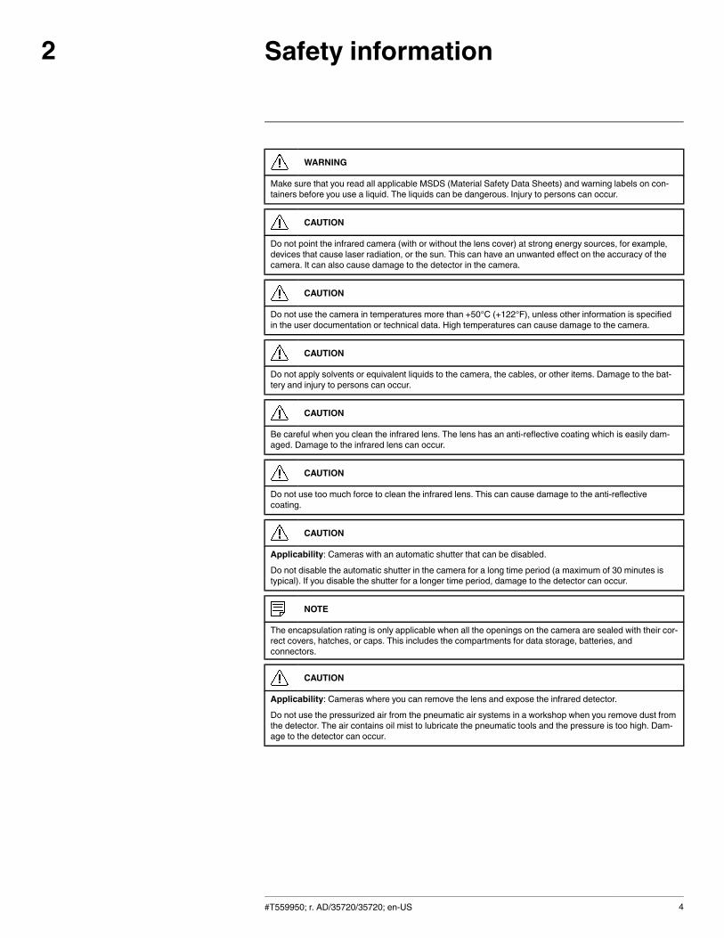
WARNING
Make sure that you read all applicable MSDS (Material Safety Data Sheets) and warning labels on con-tainers before you use a liquid. The liquids can be dangerous. Injury to persons can occur.
CAUTION
Do not point the infrared camera (with or without the lens cover) at strong energy sources, for example,devices that cause laser radiation, or the sun. This can have an unwanted effect on the accuracy of thecamera. It can also cause damage to the detector in the camera.
CAUTION
Do not use the camera in temperatures more than +50°C (+122°F), unless other information is specifiedin the user documentation or technical data. High temperatures can cause damage to the camera.
CAUTION
Do not apply solvents or equivalent liquids to the camera, the cables, or other items. Damage to the bat-tery and injury to persons can occur.
CAUTION
Be careful when you clean the infrared lens. The lens has an anti-reflective coating which is easily dam-aged. Damage to the infrared lens can occur.
CAUTION
Do not use too much force to clean the infrared lens. This can cause damage to the anti-reflectivecoating.
CAUTION
Applicability: Cameras with an automatic shutter that can be disabled.
Do not disable the automatic shutter in the camera for a long time period (a maximum of 30 minutes istypical). If you disable the shutter for a longer time period, damage to the detector can occur.
NOTE
The encapsulation rating is only applicable when all the openings on the camera are sealed with their cor-rect covers, hatches, or caps. This includes the compartments for data storage, batteries, andconnectors.
CAUTION
Applicability: Cameras where you can remove the lens and expose the infrared detector.
Do not use the pressurized air from the pneumatic air systems in a workshop when you remove dust fromthe detector. The air contains oil mist to lubricate the pneumatic tools and the pressure is too high. Dam-age to the detector can occur.
#T559950; r. AD/35720/35720; en-US 4

Notice to user3
3.1 User-to-user forums
Exchange ideas, problems, and infrared solutions with fellow thermographers around theworld in our user-to-user forums. To go to the forums, visit:
http://www.infraredtraining.com/community/boards/
3.2 Calibration
We recommend that you send in the camera for calibration once a year. Contact your localsales office for instructions on where to send the camera.
3.3 Accuracy
For very accurate results, we recommend that you wait 5 minutes after you have startedthe camera before measuring a temperature.
3.4 Disposal of electronic waste
As with most electronic products, this equipment must be disposed of in an environmen-tally friendly way, and in accordance with existing regulations for electronic waste.
Please contact your FLIR Systems representative for more details.
3.5 Training
To read about infrared training, visit:
• http://www.infraredtraining.com• http://www.irtraining.com• http://www.irtraining.eu
3.6 Documentation updates
Our manuals are updated several times per year, and we also issue product-critical notifi-cations of changes on a regular basis.
To access the latest manuals and notifications, go to the Download tab at:
http://support.flir.com
It only takes a few minutes to register online. In the download area you will also find the lat-est releases of manuals for our other products, as well as manuals for our historical andobsolete products.
3.7 Important note about this manual
FLIR Systems issues generic manuals that cover several cameras within a model line.
This means that this manual may contain descriptions and explanations that do not applyto your particular camera model.
#T559950; r. AD/35720/35720; en-US 5
Notice to user3
3.8 Note about authoritative versions
The authoritative version of this publication is English. In the event of divergences due totranslation errors, the English text has precedence.
Any late changes are first implemented in English.
#T559950; r. AD/35720/35720; en-US 6
Customer help4
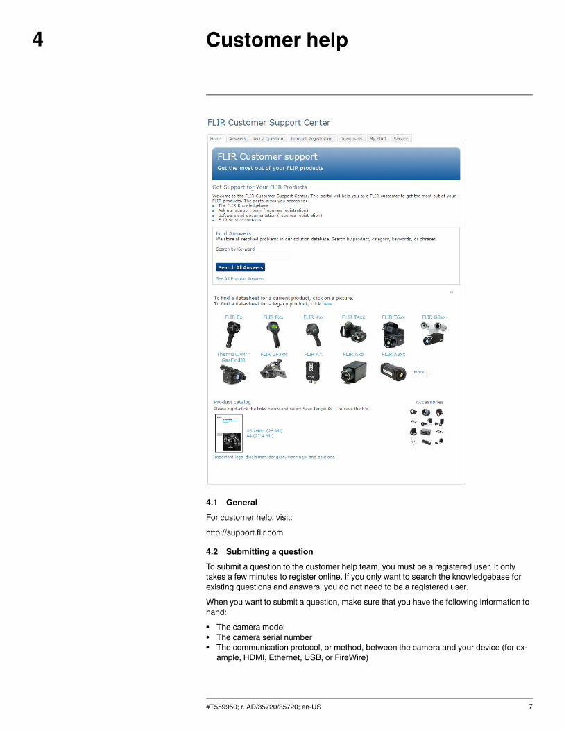
4.1 General
For customer help, visit:
http://support.flir.com
4.2 Submitting a question
To submit a question to the customer help team, you must be a registered user. It onlytakes a few minutes to register online. If you only want to search the knowledgebase forexisting questions and answers, you do not need to be a registered user.
When you want to submit a question, make sure that you have the following information tohand:
• The camera model• The camera serial number• The communication protocol, or method, between the camera and your device (for ex-ample, HDMI, Ethernet, USB, or FireWire)
#T559950; r. AD/35720/35720; en-US 7
Customer help4
• Device type (PC/Mac/iPhone/iPad/Android device, etc.)• Version of any programs from FLIR Systems• Full name, publication number, and revision number of the manual
4.3 Downloads
On the customer help site you can also download the following, when applicable for theproduct:
• Firmware updates for your infrared camera.• Program updates for your PC/Mac software.• Freeware and evaluation versions of PC/Mac software.• User documentation for current, obsolete, and historical products.• Mechanical drawings (in *.dxf and *.pdf format).• Cad data models (in *.stp format).• Application stories.• Technical datasheets.• Product catalogs.
#T559950; r. AD/35720/35720; en-US 8

Installation (FLIR A6xx cameras)5
5.1 General information
5.1.1 Explanation
The following programs are included on the ThermoVision System Tools & Utilities appli-cation CD:
• FLIR IP Config: A set-up and configuration program to detect and find FLIR automationand science cameras on a network and automatically assign or manually set IPaddresses.
• FLIR IR Monitor: A program to control FLIR automation and science cameras on a net-work. You typically use FLIR IR Monitor to change camera settings, lay out measure-ment tools on the screen, set up alarms, etc.
• FLIR IR Camera Player: A PC-based remote control and video player for infrared cam-eras from FLIR Systems.
• A link to a web installation of FLIR Axxx Control & Image Interfaces: An installation thatincludes Interface Control Documents (ICDs), user documentation, and Ccode exam-ples. We recommend that you read the documentation.
5.1.2 Default installation paths
• C:\Program Files\FLIR Systems\FLIR IP Config• C:\Program Files\FLIR Systems\FLIR IR Monitor• C:\Program Files\FLIR Systems\FLIR IR Camera Player• C:\Program Files\FLIR Systems\AXXX Control & Image Interfaces
Note Functionality in the PC programs is dependent on the camera model.
5.2 System requirements
5.2.1 Operating system
• Microsoft Windows XP Professional, with Service Pack 2 (SP2).• Microsoft Windows Vista Ultimate 32-bit.• Microsoft Windows 7, 32-bit and 64-bit.
5.2.2 Hardware
• Personal computer with a 2 GHz 32-bit or 64-bit processor.• 1 GB of RAM or more.• 20 GB of hard disk space.• Super VGA (1024 × 768) or higher-resolution monitor.• Support for DirectX 9 graphics with:
◦ WDDM driver◦ 128 MB of graphics memory (minimum)◦ Pixel Shader 2.0 (in hardware)◦ 32 bits per pixel.
• DVD-ROM drive.• Audio output.• Keyboard and Microsoft mouse, or a compatible pointing device.
5.2.3 Software
Microsoft Internet Explorer 6 or later.
#T559950; r. AD/35720/35720; en-US 9
Installation (FLIR A6xx cameras)5
5.2.4 More information
For specific information about system requirements for the operating systems mentionedabove, visit http://www.microsoft.com/windows/.
5.3 Installation
5.3.1 General
Last-minute changes and other important information can be found in the read-me file onthe CD-ROM. We recommend that you read this file before you install the programs.
Note
• If you experience problems during the installation, visit our Customer Help at http://sup-port.flir.com.
• You must be an Administrator or a user with Administrative Rights to install theprograms.
• A complete installation consists of several subinstallations, some of which are fromthird-party vendors. Do not abort these subinstallations, as they are needed for thecomplete installation.
• A complete installation can take up to 10 minutes to complete.
5.3.2 ProcedureFollow this procedure:1. Close down all applications.2. Insert the ThermoVision System Tools & Utilities CD-ROM into the CD drive on the
computer. The installation should start automatically.
Should the installation not start automatically, start Windows Explorer and double-clickSETUP.HTM on the CD-ROM.
3. Click one of the following:
• Install FLIR IP Config.• Install FLIR IR Monitor.• Install FLIR IR Camera Player.• Install AXXX Control & Image Interfaces.
4. Follow the on-screen instructions.
#T559950; r. AD/35720/35720; en-US 10
Installation (FLIR A6xx sccameras)
6
The FLIR A6xx sc cameras are supported by the FLIR ResearchIR software. A downloadcard for this software is included in the camera package.
To install the software, follow the procedure in the user’s manual for FLIR ResearchIR. Theuser’s manual is available in the User documentation > Software folder on the User docu-mentation CD-ROM that comes with the camera.
#T559950; r. AD/35720/35720; en-US 11
Quick start guide7
7.1 Quick start guide, FLIR A6xx series
Follow this procedure:
1. Connect the power and Ethernet cables to the camera.2. Connect the power cable to a power supply.3. Connect the camera to the network, using the Ethernet cable.4. Use to identify the unit in the network and set the IP address if necessary. Download
from http://tinyurl.com/o5wudd7.5. Use FLIR Tools to set up and control the camera. For more information, see section
7.1.1 Download FLIR Tools, page 12.
7.1.1 Download FLIR Tools
FLIR Tools lets you quickly create professional inspection reports that clearly show deci-sion makers what you’ve found with your IR camera.
Import, analyze, and fine-tune images easily. Then incorporate them into concise docu-ments to share findings and justify repairs.
Go to the following website to download FLIR Tools:
http://support.flir.com/tools
7.2 Quick start guide, FLIR A6xx sc series
Follow this procedure:
1. Go to http://support.flir.com/rir4 and download FLIR ResearchIR Max.2. Install FLIR ResearchIR Max.3. Start FLIR ResearchIR Max.
When asked for the license key, enter the license key that is printed on the FLIR Re-searchIR Max download card. The card is included with your camera.
4. Connect the camera to the computer using the provided Ethernet cable.5. Start the camera. This displays a start-up dialog box in FLIR ResearchIR Max. If the
start-up dialog box is not displayed, go to View > Startup Dialog.6. In the start-up dialog box, click the camera you want to connect to.
For more information about the installation and connection processes, see the FLIR Re-searchIR Max manual.
#T559950; r. AD/35720/35720; en-US 12
List of accessories and services8
IR lens, f=41.3 mm (15°) with case T197914
IR lens, f=24.6 mm (25°) with case T197922
IR lens, f=13.1 mm (45°) with case T197915
Close-up IR lens, 2.9× (50 µm) with case T198059
Close-up IR lens, 5.8× (100 µm) with case T198060
IR lens, f=6.5 mm (80°) with case T198065
IR lens, f=88.9 mm (7°) with case and support forA6xx/A6xxsc
T198165
Close-up IR lens, 1.5× (25 µm) with case T198066
High temp option +300°C to 2000°C (+572°F to3632°F) for FLIR A6xxsc and T6xx
T197896
Power cord EU 1910400
Power cord US 1910401
Power cord UK 1910402
Power supply, incl. multi plugs, for A3xx, A3xxsc,A6xx and A6xxsc
T910922
Power supply for A3xx f, IP66 T911182
USB cable Std A <-> Mini-B 1910423
Ethernet cable CAT-6, 2m/6.6 ft. T951004ACC
Power cable, pigtailed 1910586ACC
Hard transport case for A3xx/A6xx series T197871ACC
Cardboard box for A3xx/A6xx series T197870ACC
Filter holder for A6xx lenses T126889ACC
FLIR Tools T198584
FLIR Tools+ (license only) T198583
FLIR IR Camera Player DSW-10000
FLIR ResearchIR 3 (license only) T198578
FLIR ResearchIR 3 Max (license only) T198574
FLIR ResearchIR Max + HSDR 4 T198697
FLIR ResearchIR Max + HSDR 4 T199014
FLIR ResearchIR Max + HSDR 4 Upgrade T199044
FLIR ResearchIR Max 4 T198696
FLIR ResearchIR Max 4 T199013
FLIR ResearchIR Max 4 Upgrade T199043
FLIR ResearchIR Standard 4 T198731
FLIR ResearchIR Standard 4 T199012
FLIR ResearchIR Standard 4 Upgrade T199042
ThermoVision™ System Developers Kit Ver. 2.6 T198567
ThermoVision™ LabVIEW® Digital Toolkit Ver. 3.3 T198566
One year extended warranty for A6xx, A6xxscseries
T199827
#T559950; r. AD/35720/35720; en-US 13
List of accessories and services8
Note FLIR Systems reserves the right to discontinue models, parts or accessories, andother items, or to change specifications at any time without prior notice.
#T559950; r. AD/35720/35720; en-US 14
Mechanical installation9
9.1 Mounting interfaces
The camera unit has been designed to allow it to be installed in any position. The housinghas three mounting interfaces—bottom, left, and right—each with the following threadedholes.
• 2 × M4 metric threaded holes.• 1 × UNC ¼-20 standard tripod mount.
9.2 Notes on permanent installation
If the camera unit is to be permanently installed at the application site, certain steps arerequired.
The camera unit might need to be enclosed in a protective housing and, depending on theambient conditions (e.g., temperature), the housing may need to be cooled or heated bywater or air.
In very dusty conditions the installation might also need to have a stream of pressurizedair directed at the lens, to prevent dust build-up.
9.3 Vibrations
When installing the camera unit in harsh industrial environments, every precaution shouldbe taken when securing the unit.
If the environment exposes the unit to severe vibrations, there may be a need to securethe mounting screws by means of Loctite or another industrial brand of thread-lockingliquid, as well as to dampen the vibrations by installing the camera unit on a specially de-signed base.
9.4 Further information
For further information regarding installation recommendations and environmental enclo-sures, contact FLIR Systems.
9.5 Cable strain relief
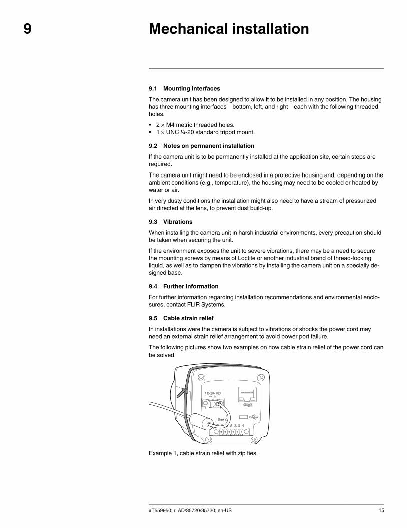
In installations were the camera is subject to vibrations or shocks the power cord mayneed an external strain relief arrangement to avoid power port failure.
The following pictures show two examples on how cable strain relief of the power cord canbe solved.
Example 1, cable strain relief with zip ties.
#T559950; r. AD/35720/35720; en-US 15
Mechanical installation9
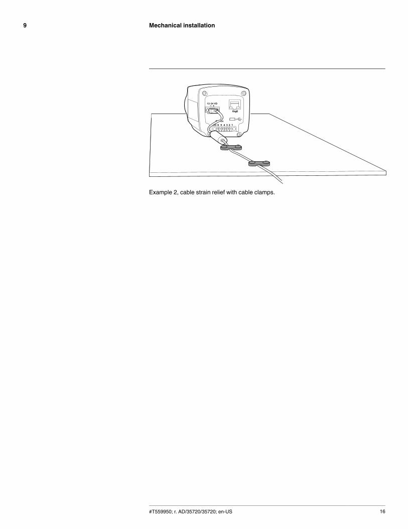
Example 2, cable strain relief with cable clamps.
#T559950; r. AD/35720/35720; en-US 16
Mounting and removing lenses10
10.1 Removing an infrared lens
Note
• Do not touch the lens surface when you remove an infrared lens. If this happens, cleanthe lens according to the instructions in section 20.2 Infrared lens, page 81.
• When you have removed the lens, put the lens caps on the lens immediately, to protectit from dust and fingerprints.
10.2 ProcedureFollow this procedure to remove an infrared lens:1. Rotate the lens counter-clockwise 30° (looking at the front of the lens).2. Carefully pull out the lens from the bayonet ring.
10.3 Mounting an infrared lens
Note Do not touch the lens surface when you mount an infrared lens. If this happens,clean the lens according to the instructions in section 20.2 Infrared lens, page 81.
10.3.1 ProcedureFollow this procedure to mount an infrared lens:1. Correctly position the lens in front of the bayonet ring.2. Carefully push the lens into position.3. Rotate the lens 30° clockwise (looking at the front of the lens) until a click is heard.
#T559950; r. AD/35720/35720; en-US 17
Connectors, controls, andindicators
11
11.1 Explanation
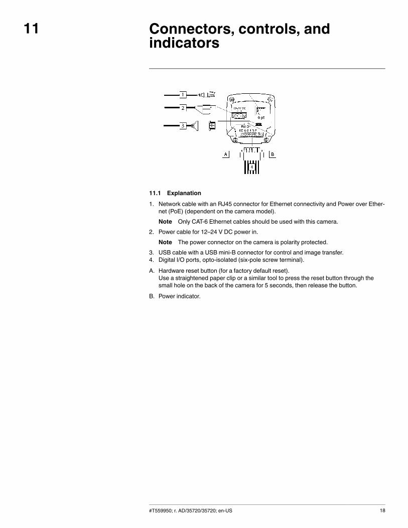
1. Network cable with an RJ45 connector for Ethernet connectivity and Power over Ether-net (PoE) (dependent on the camera model).Note Only CAT-6 Ethernet cables should be used with this camera.
2. Power cable for 12–24 V DC power in.Note The power connector on the camera is polarity protected.
3. USB cable with a USB mini-B connector for control and image transfer.4. Digital I/O ports, opto-isolated (six-pole screw terminal).
A. Hardware reset button (for a factory default reset).Use a straightened paper clip or a similar tool to press the reset button through thesmall hole on the back of the camera for 5 seconds, then release the button.
B. Power indicator.
#T559950; r. AD/35720/35720; en-US 18
Example system overviews12
12.1 FLIR A6xx series
12.1.1 Figure
12.1.2 Explanation
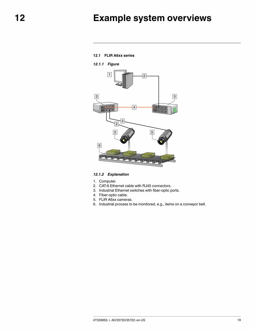
1. Computer.2. CAT-6 Ethernet cable with RJ45 connectors.3. Industrial Ethernet switches with fiber-optic ports.4. Fiber-optic cable.5. FLIR A6xx cameras.6. Industrial process to be monitored, e.g., items on a conveyor belt.
#T559950; r. AD/35720/35720; en-US 19
Example system overviews12
12.1.3 Figure
12.1.4 Explanation
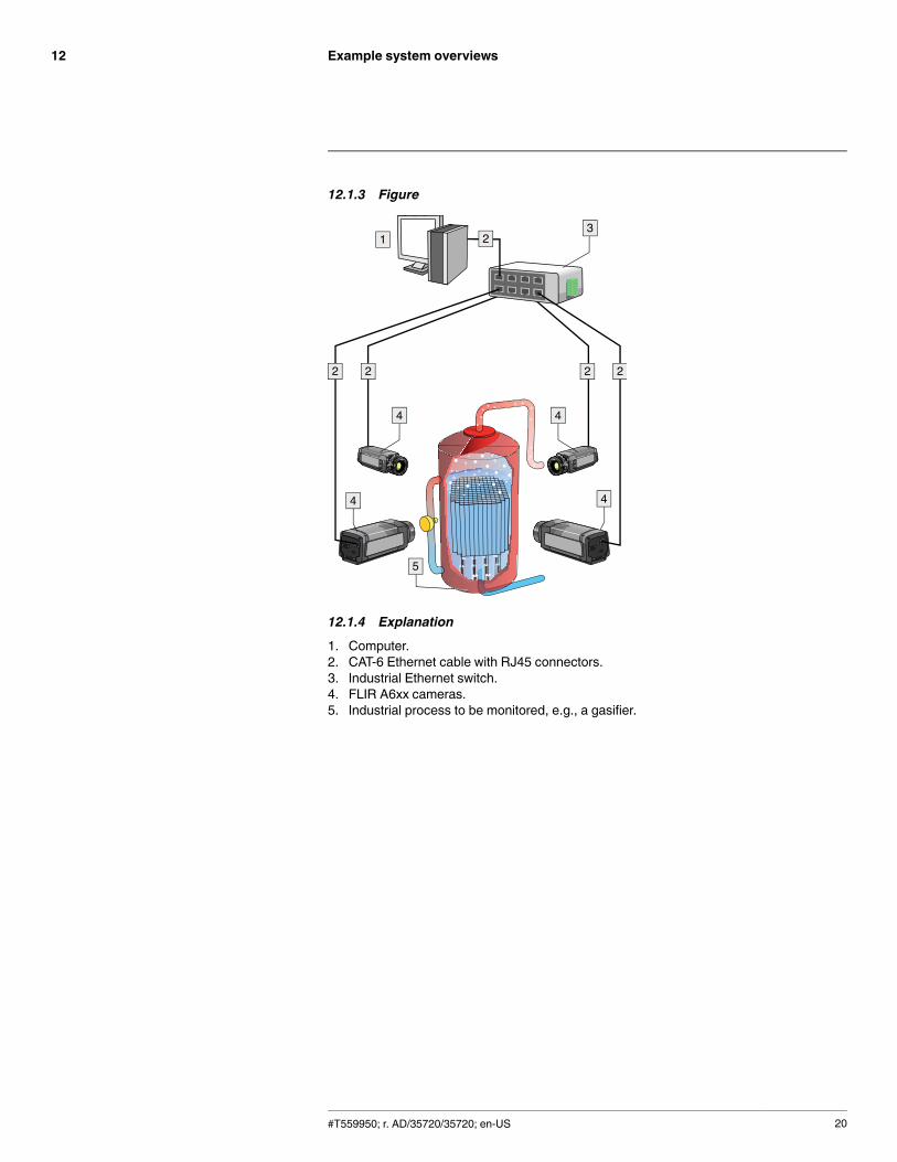
1. Computer.2. CAT-6 Ethernet cable with RJ45 connectors.3. Industrial Ethernet switch.4. FLIR A6xx cameras.5. Industrial process to be monitored, e.g., a gasifier.
#T559950; r. AD/35720/35720; en-US 20
Example system overviews12
12.1.5 Figure
12.1.6 Explanation
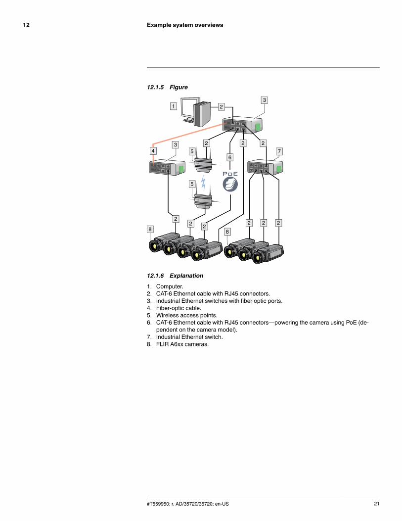
1. Computer.2. CAT-6 Ethernet cable with RJ45 connectors.3. Industrial Ethernet switches with fiber optic ports.4. Fiber-optic cable.5. Wireless access points.6. CAT-6 Ethernet cable with RJ45 connectors—powering the camera using PoE (de-
pendent on the camera model).7. Industrial Ethernet switch.8. FLIR A6xx cameras.
#T559950; r. AD/35720/35720; en-US 21
Example system overviews12
12.2 FLIR A6xx sc series
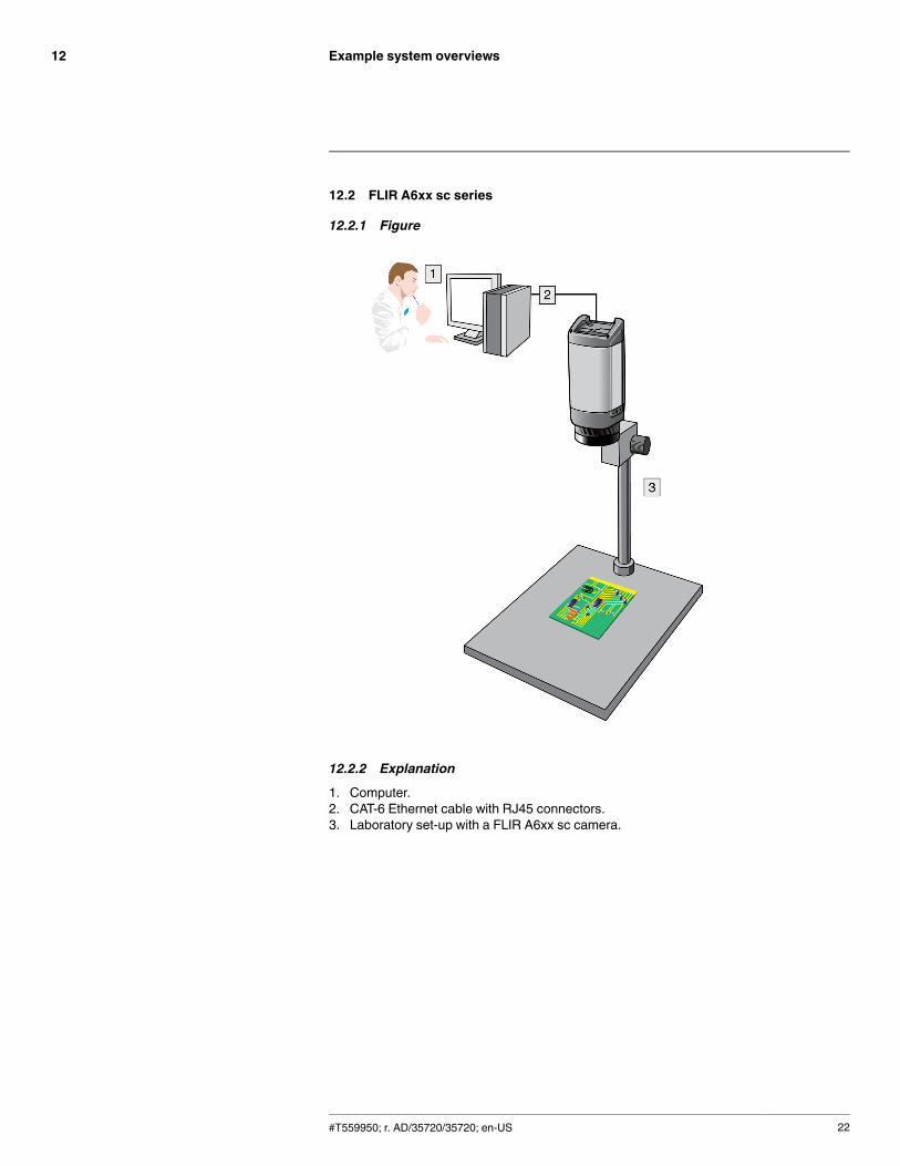
12.2.1 Figure
12.2.2 Explanation
1. Computer.2. CAT-6 Ethernet cable with RJ45 connectors.3. Laboratory set-up with a FLIR A6xx sc camera.
#T559950; r. AD/35720/35720; en-US 22
Digital I/O functionality13
13.1 FLIR A615 and A655sc
• The state (high or low voltage) on an input pin is used to mark images for use by anapplication.
• The state (high or low voltage) on an output pin is controlled by an application.
See the section Technical data for details on voltages, etc.
#T559950; r. AD/35720/35720; en-US 23
Technical data14
14.1 Online field-of-view calculator
Please visit http://support.flir.com and click the photo of the camera series for field-of-viewtables for all lens–camera combinations.
14.2 Note about technical data
FLIR Systems reserves the right to change specifications at any time without prior notice.Please check http://support.flir.com for latest changes.
14.3 Note about authoritative versions
The authoritative version of this publication is English. In the event of divergences due totranslation errors, the English text has precedence.
Any late changes are first implemented in English.
#T559950; r. AD/35720/35720; en-US 24
Technical data14
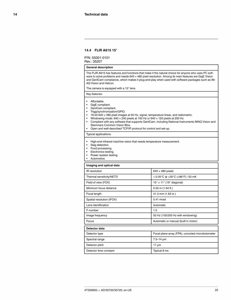
14.4 FLIR A615 15°
P/N: 55001-0101Rev.: 35207General description
The FLIR A615 has features and functions that make it the natural choice for anyone who uses PC soft-ware to solve problems and needs 640 × 480 pixel resolution. Among its main features are GigE Visionand GenICam compliance, which makes it plug-and-play when used with software packages such as IM-AQ Vision and Halcon.
The camera is equipped with a 15° lens.
Key features:
• Affordable.• GigE compliant.• GenICam compliant.• Trigg/synchronization/GPIO.• 16-bit 640 × 480 pixel images at 50 Hz, signal, temperature linear, and radiometric.• Windowing mode: 640 × 240 pixels at 100 Hz or 640 × 120 pixels at 200 Hz.• Compliant with any software that supports GenICam, including National Instruments IMAQ Vision and
Stemmers Common Vision Blox.• Open and well-described TCP/IP protocol for control and set-up.
Typical applications:
• High-end infrared machine vision that needs temperature measurement.• Slag detection.• Food processing.• Electronics testing.• Power resistor testing.• Automotive.
Imaging and optical data
IR resolution 640 × 480 pixels
Thermal sensitivity/NETD < 0.05°C @ +30°C (+86°F) / 50 mK
Field of view (FOV) 15° × 11° (19° diagonal)
Minimum focus distance 0.50 m (1.64 ft.)
Focal length 41.3 mm (1.63 in.)
Spatial resolution (IFOV) 0.41 mrad
Lens identification Automatic
F-number 1.0
Image frequency 50 Hz (100/200 Hz with windowing)
Focus Automatic or manual (built in motor)
Detector data
Detector type Focal plane array (FPA), uncooled microbolometer
Spectral range 7.5–14 µm
Detector pitch 17 µm
Detector time constant Typical 8 ms
#T559950; r. AD/35720/35720; en-US 25

Technical data14
Measurement
Object temperature range • –40°C to +150°C (–40°F to +302°F)• 100 to +650°C (+212 to +1202°F)• 300 to +2000°C (+572 to +3632°F)
Accuracy ±2°C (±3.6°F) or ±2% of reading
Measurement analysis
Atmospheric transmission correction Automatic, based on inputs for distance, atmos-pheric temperature and relative humidity
Optics transmission correction Automatic, based on signals from internal sensors
Emissivity correction Variable from 0.01 to 1.0
Reflected apparent temperature correction Automatic, based on input of reflected temperature
External optics/windows correction Automatic, based on input of optics/window trans-mission and temperature
Measurement corrections Global object parameters
USB
USB • Control and image
USB, standard USB 2 HS
USB, connector type • USB Mini-B
USB, communication TCP/IP socket-based FLIR proprietary
USB, image streaming 16-bit 640 × 480 pixels @ 25 Hz
• Signal linear• Temperature linear• Radiometric
USB, protocols TCP, UDP, SNTP, RTSP, RTP, HTTP, ICMP, IGMP,ftp, SMTP, SMB (CIFS), DHCP, MDNS (Bonjour),uPnP
Ethernet
Ethernet Control and image
Ethernet, type Gigabit Ethernet
Ethernet, standard IEEE 802.3
Ethernet, connector type RJ-45
Ethernet, communication TCP/IP socket-based FLIR proprietary and GenI-Cam protocol
Ethernet, image streaming 16-bit 640 × 480 pixels @ 50 Hz
16-bit 640 × 240 pixels @ 100 Hz
16-bit 640 × 120 pixels @ 200 Hz
• Signal linear• Temperature linear• Radiometric
GigE Vision and GenICam compatible
Ethernet, protocols TCP, UDP, SNTP, RTSP, RTP, HTTP, ICMP, IGMP,ftp, SMTP, SMB (CIFS), DHCP, MDNS (Bonjour),uPnP
#T559950; r. AD/35720/35720; en-US 26

Technical data14
Digital input/output
Digital input, purpose Image tag (start, stop, general), Image flow control,(stream on/off), Input ext. device (programmaticallyread)
Digital input 2 opto-isolated, 0–1.5 V = low, 3–25 V = high
Digital output, purpose Output to ext. device (programmatically set)
Digital output 2 opto-isolated, ON = supply (max. 100 mA), OFF= open
Digital I/O, isolation voltage 500 VRMS
Digital I/O, supply voltage 6–24 VDC, max. 200 mA
Digital I/O, connector type 6-pole jackable screw terminal
Power system
External power operation 12/24 VDC, 24 W absolute max.
External power, connector type 2-pole jackable screw terminal
Voltage Allowed range 10–30 VDC
Environmental data
Operating temperature range –15°C to +50°C (+5°F to +122°F)
Storage temperature range –40°C to +70°C (–40°F to +158°F)
Humidity (operating and storage) IEC 60068-2-30/24 h 95% relative humidity +25°Cto +40°C (+77°F to +104°F)
EMC • EN 61000-6-2:2001 (Immunity)• EN 61000-6-3:2001 (Emission)• FCC 47 CFR Part 15 Class B (Emission)
Encapsulation IP 30 (IEC 60529)
Shock 25 g (IEC 60068-2-27)
Vibration 2 g (IEC 60068-2-6)
Physical data
Weight 0.92 kg (2.03 lb.)
Camera size (L × W × H) 222× 73 × 75 mm (8.7 × 2.9 × 3.0 in.)
Camera size, excl. lens (L × W × H) 203× 73 × 75 mm (8.0 × 2.9 × 3.0 in.)
Tripod mounting UNC ¼"-20 (on three sides)
Base mounting 2 × M4 thread mounting holes (on three sides)
Housing material Aluminum
Comments to physical data Outline dimensional drawings and STEP files canbe found at http://support.flir.com
#T559950; r. AD/35720/35720; en-US 27

Technical data14
Shipping information
Packaging, type Cardboard box
List of contents • Infrared camera with lens• Ethernet cable• Mains cable• Power cable, pig-tailed• Power supply• Printed documentation• USB cable• Utility CD-ROM
Packaging, weight
Packaging, size 360 × 180 × 550 mm (14.2 × 7.1 × 21.7 in.)
EAN-13 7332558003244
UPC-12 845188002725
Country of origin Sweden
Supplies & accessories:
• T197914; IR lens, f=41.3 mm (15°) with case• T197922; IR lens, f=24.6 mm (25°) with case• T197915; IR lens, f=13.1 mm (45°) with case• T198065; IR lens, f=6.5 mm (80°) with case• T198165; IR lens, f=88.9 mm (7°) with case and support for A6xx/A6xxsc• T197896; High temperature option +300°C to 2000°C (+572°F to 3632°F)• 1910400; Power cord EU• 1910401; Power cord US• 1910402; Power cord UK• T910922; Power supply, incl. multi plugs, for A3xx, A3xxsc, A6xx and A6xxsc• T911182; Power supply for A3xx f, IP66• 1910423; USB cable Std A <-> Mini-B• T951004ACC; Ethernet cable CAT6, 2 m/6.6 ft.• 1910586ACC; Power cable, pigtailed• T197871ACC; Hard transport case for A3xx/A6xx series• T197870ACC; Cardboard box for A3xx/A6xx series• T126889ACC; Filter holder for A6xx lenses• T198584; FLIR Tools• T198583; FLIR Tools+ (download card incl. license key)• DSW-10000; FLIR IR Camera Player• T199233; FLIR Atlas SDK for .NET• T199234; FLIR Atlas SDK for MATLAB• T198567; ThermoVision™ System Developers Kit Ver. 2.6• T198566; ThermoVision™ LabVIEW® Digital Toolkit Ver. 3.3
#T559950; r. AD/35720/35720; en-US 28

Technical data14
14.5 FLIR A615 25°
P/N: 55001-0102Rev.: 35207General description
The FLIR A615 has features and functions that make it the natural choice for anyone who uses PC soft-ware to solve problems and needs 640 × 480 pixel resolution. Among its main features are GigE Visionand GenICam compliance, which makes it plug-and-play when used with software packages such as IM-AQ Vision and Halcon.
The camera is equipped with the standard 25° lens.
Key features:
• Affordable.• GigE compliant.• GenICam compliant.• Trigg/synchronization/GPIO.• 16-bit 640 × 480 pixel images at 50 Hz, signal, temperature linear, and radiometric.• Windowing mode: 640 × 240 pixels at 100 Hz or 640 × 120 pixels at 200 Hz.• Compliant with any software that supports GenICam, including National Instruments IMAQ Vision and
Stemmers Common Vision Blox.• Open and well-described TCP/IP protocol for control and set-up.
Typical applications:
• High-end infrared machine vision that requires temperature measurement• Slag detection• Food processing• Electronics testing• Power resistor testing• Automotive
Imaging and optical data
IR resolution 640 × 480 pixels
Thermal sensitivity/NETD < 0.05°C @ +30°C (+86°F) / 50 mK
Field of view (FOV) 25° × 19° (31° diagonal)
Minimum focus distance 0.25 m (0.82 ft.)
Focal length 24.6 mm (0.97 in.)
Spatial resolution (IFOV) 0.68 mrad
Lens identification Automatic
F-number 1.0
Image frequency 50 Hz (100/200 Hz with windowing)
Focus Automatic or manual (built in motor)
Detector data
Detector type Focal plane array (FPA), uncooled microbolometer
Spectral range 7.5–14 µm
Detector pitch 17 µm
Detector time constant Typical 8 ms
#T559950; r. AD/35720/35720; en-US 29

Technical data14
Measurement
Object temperature range • –40°C to +150°C (–40°F to +302°F)• 100 to +650°C (+212 to +1202°F)• 300 to +2000°C (+572 to +3632°F)
Accuracy ±2°C (±3.6°F) or ±2% of reading
Measurement analysis
Atmospheric transmission correction Automatic, based on inputs for distance, atmos-pheric temperature and relative humidity
Optics transmission correction Automatic, based on signals from internal sensors
Emissivity correction Variable from 0.01 to 1.0
Reflected apparent temperature correction Automatic, based on input of reflected temperature
External optics/windows correction Automatic, based on input of optics/window trans-mission and temperature
Measurement corrections Global object parameters
USB
USB • Control and image
USB, standard USB 2 HS
USB, connector type • USB Mini-B
USB, communication TCP/IP socket-based FLIR proprietary
USB, image streaming 16-bit 640 × 480 pixels @ 25 Hz
• Signal linear• Temperature linear• Radiometric
USB, protocols TCP, UDP, SNTP, RTSP, RTP, HTTP, ICMP, IGMP,ftp, SMTP, SMB (CIFS), DHCP, MDNS (Bonjour),uPnP
Ethernet
Ethernet Control and image
Ethernet, type Gigabit Ethernet
Ethernet, standard IEEE 802.3
Ethernet, connector type RJ-45
Ethernet, communication TCP/IP socket-based FLIR proprietary and GenI-Cam protocol
Ethernet, image streaming 16-bit 640 × 480 pixels @ 50 Hz
16-bit 640 × 240 pixels @ 100 Hz
16-bit 640 × 120 pixels @ 200 Hz
• Signal linear• Temperature linear• Radiometric
GigE Vision and GenICam compatible
Ethernet, protocols TCP, UDP, SNTP, RTSP, RTP, HTTP, ICMP, IGMP,ftp, SMTP, SMB (CIFS), DHCP, MDNS (Bonjour),uPnP
#T559950; r. AD/35720/35720; en-US 30

Technical data14
Digital input/output
Digital input, purpose Image tag (start, stop, general), Image flow control,(stream on/off), Input ext. device (programmaticallyread)
Digital input 2 opto-isolated, 0–1.5 V = low, 3–25 V = high
Digital output, purpose Output to ext. device (programmatically set)
Digital output 2 opto-isolated, ON = supply (max. 100 mA), OFF= open
Digital I/O, isolation voltage 500 VRMS
Digital I/O, supply voltage 6–24 VDC, max. 200 mA
Digital I/O, connector type 6-pole jackable screw terminal
Power system
External power operation 12/24 VDC, 24 W absolute max.
External power, connector type 2-pole jackable screw terminal
Voltage Allowed range 10–30 VDC
Environmental data
Operating temperature range –15°C to +50°C (+5°F to +122°F)
Storage temperature range –40°C to +70°C (–40°F to +158°F)
Humidity (operating and storage) IEC 60068-2-30/24 h 95% relative humidity +25°Cto +40°C (+77°F to +104°F)
EMC • EN 61000-6-2:2001 (Immunity)• EN 61000-6-3:2001 (Emission)• FCC 47 CFR Part 15 Class B (Emission)
Encapsulation IP 30 (IEC 60529)
Shock 25 g (IEC 60068-2-27)
Vibration 2 g (IEC 60068-2-6)
Physical data
Weight 0.90 kg (1.98 lb.)
Camera size (L × W × H) 216× 73 × 75 mm (8.5 × 2.9 × 3.0 in.)
Camera size, excl. lens (L × W × H) 203× 73 × 75 mm (8.0 × 2.9 × 3.0 in.)
Tripod mounting UNC ¼"-20 (on three sides)
Base mounting 2 × M4 thread mounting holes (on three sides)
Housing material Aluminum
Comments to physical data Outline dimensional drawings and STEP files canbe found at http://support.flir.com
#T559950; r. AD/35720/35720; en-US 31
Technical data14
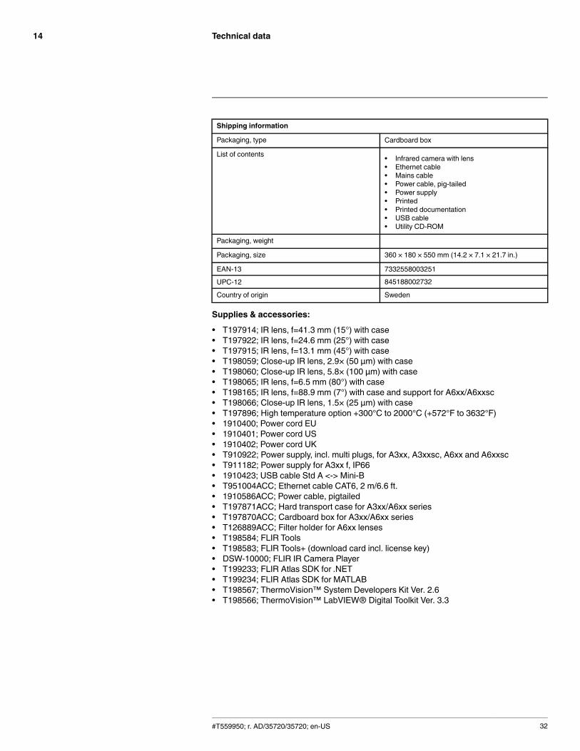
Shipping information
Packaging, type Cardboard box
List of contents • Infrared camera with lens• Ethernet cable• Mains cable• Power cable, pig-tailed• Power supply• Printed• Printed documentation• USB cable• Utility CD-ROM
Packaging, weight
Packaging, size 360 × 180 × 550 mm (14.2 × 7.1 × 21.7 in.)
EAN-13 7332558003251
UPC-12 845188002732
Country of origin Sweden
Supplies & accessories:
• T197914; IR lens, f=41.3 mm (15°) with case• T197922; IR lens, f=24.6 mm (25°) with case• T197915; IR lens, f=13.1 mm (45°) with case• T198059; Close-up IR lens, 2.9× (50 µm) with case• T198060; Close-up IR lens, 5.8× (100 µm) with case• T198065; IR lens, f=6.5 mm (80°) with case• T198165; IR lens, f=88.9 mm (7°) with case and support for A6xx/A6xxsc• T198066; Close-up IR lens, 1.5× (25 µm) with case• T197896; High temperature option +300°C to 2000°C (+572°F to 3632°F)• 1910400; Power cord EU• 1910401; Power cord US• 1910402; Power cord UK• T910922; Power supply, incl. multi plugs, for A3xx, A3xxsc, A6xx and A6xxsc• T911182; Power supply for A3xx f, IP66• 1910423; USB cable Std A <-> Mini-B• T951004ACC; Ethernet cable CAT6, 2 m/6.6 ft.• 1910586ACC; Power cable, pigtailed• T197871ACC; Hard transport case for A3xx/A6xx series• T197870ACC; Cardboard box for A3xx/A6xx series• T126889ACC; Filter holder for A6xx lenses• T198584; FLIR Tools• T198583; FLIR Tools+ (download card incl. license key)• DSW-10000; FLIR IR Camera Player• T199233; FLIR Atlas SDK for .NET• T199234; FLIR Atlas SDK for MATLAB• T198567; ThermoVision™ System Developers Kit Ver. 2.6• T198566; ThermoVision™ LabVIEW® Digital Toolkit Ver. 3.3
#T559950; r. AD/35720/35720; en-US 32

Technical data14
14.6 FLIR A615 45°
P/N: 55001-0103Rev.: 35207General description
The FLIR A615 has features and functions that make it the natural choice for anyone who uses PC soft-ware to solve problems and needs 640 × 480 pixel resolution. Among its main features are GigE Visionand GenICam compliance, which makes it plug-and-play when used with software packages such as IM-AQ Vision and Halcon.
The camera is equipped with a 45° lens.
Key features:
• Affordable.• GigE compliant.• GenICam compliant.• Trigg/synchronization/GPIO.• 16-bit 640 × 480 pixel images at 50 Hz, signal, temperature linear, and radiometric.• Windowing mode: 640 × 240 pixels at 100 Hz or 640 × 120 pixels at 200 Hz.• Compliant with any software that supports GenICam, including National Instruments IMAQ Vision and
Stemmers Common Vision Blox.• Open and well-described TCP/IP protocol for control and set-up.
Typical applications:
• High-end infrared machine vision that requires temperature measurement.• Slag detection.• Food processing.• Electronics testing.• Power resistor testing.• Automotive.
Imaging and optical data
IR resolution 640 × 480 pixels
Thermal sensitivity/NETD < 0.05°C @ +30°C (+86°F) / 50 mK
Field of view (FOV) 45° × 34° (55° diagonal)
Minimum focus distance 0.15 m (0.49 ft.)
Focal length 13.1 mm (0.52 in.)
Spatial resolution (IFOV) 1.23 mrad
Lens identification Automatic
F-number 1.0
Image frequency 50 Hz (100/200 Hz with windowing)
Focus Automatic or manual (built in motor)
Detector data
Detector type Focal plane array (FPA), uncooled microbolometer
Spectral range 7.5–14 µm
Detector pitch 17 µm
Detector time constant Typical 8 ms
#T559950; r. AD/35720/35720; en-US 33

Technical data14
Measurement
Object temperature range • –40°C to +150°C (–40°F to +302°F)• 100 to +650°C (+212 to +1202°F)• 300 to +2000°C (+572 to +3632°F)
Accuracy ±2°C (±3.6°F) or ±2% of reading
Measurement analysis
Atmospheric transmission correction Automatic, based on inputs for distance, atmos-pheric temperature and relative humidity
Optics transmission correction Automatic, based on signals from internal sensors
Emissivity correction Variable from 0.01 to 1.0
Reflected apparent temperature correction Automatic, based on input of reflected temperature
External optics/windows correction Automatic, based on input of optics/window trans-mission and temperature
Measurement corrections Global object parameters
USB
USB • Control and image
USB, standard USB 2 HS
USB, connector type • USB Mini-B
USB, communication TCP/IP socket-based FLIR proprietary
USB, image streaming 16-bit 640 × 480 pixels @ 25 Hz
• Signal linear• Temperature linear• Radiometric
USB, protocols TCP, UDP, SNTP, RTSP, RTP, HTTP, ICMP, IGMP,ftp, SMTP, SMB (CIFS), DHCP, MDNS (Bonjour),uPnP
Ethernet
Ethernet Control and image
Ethernet, type Gigabit Ethernet
Ethernet, standard IEEE 802.3
Ethernet, connector type RJ-45
Ethernet, communication TCP/IP socket-based FLIR proprietary and GenI-Cam protocol
Ethernet, image streaming 16-bit 640 × 480 pixels @ 50 Hz
16-bit 640 × 240 pixels @ 100 Hz
16-bit 640 × 120 pixels @ 200 Hz
• Signal linear• Temperature linear• Radiometric
GigE Vision and GenICam compatible
Ethernet, protocols TCP, UDP, SNTP, RTSP, RTP, HTTP, ICMP, IGMP,ftp, SMTP, SMB (CIFS), DHCP, MDNS (Bonjour),uPnP
#T559950; r. AD/35720/35720; en-US 34

Technical data14
Digital input/output
Digital input, purpose Image tag (start, stop, general), Image flow control,(stream on/off), Input ext. device (programmaticallyread)
Digital input 2 opto-isolated, 0–1.5 V = low, 3–25 V = high
Digital output, purpose Output to ext. device (programmatically set)
Digital output 2 opto-isolated, ON = supply (max. 100 mA), OFF= open
Digital I/O, isolation voltage 500 VRMS
Digital I/O, supply voltage 6–24 VDC, max. 200 mA
Digital I/O, connector type 6-pole jackable screw terminal
Power system
External power operation 12/24 VDC, 24 W absolute max.
External power, connector type 2-pole jackable screw terminal
Voltage Allowed range 10–30 VDC
Environmental data
Operating temperature range –15°C to +50°C (+5°F to +122°F)
Storage temperature range –40°C to +70°C (–40°F to +158°F)
Humidity (operating and storage) IEC 60068-2-30/24 h 95% relative humidity +25°Cto +40°C (+77°F to +104°F)
EMC • EN 61000-6-2:2001 (Immunity)• EN 61000-6-3:2001 (Emission)• FCC 47 CFR Part 15 Class B (Emission)
Encapsulation IP 30 (IEC 60529)
Shock 25 g (IEC 60068-2-27)
Vibration 2 g (IEC 60068-2-6)
Physical data
Weight 0.94 kg (2.07 lb.)
Camera size (L × W × H) 225× 73 × 75 mm (8.8 × 2.9 × 3.0 in.)
Camera size, excl. lens (L × W × H) 203× 73 × 75 mm (8.0 × 2.9 × 3.0 in.)
Tripod mounting UNC ¼"-20 (on three sides)
Base mounting 2 × M4 thread mounting holes (on three sides)
Housing material Aluminum
Comments to physical data Outline dimensional drawings and STEP files canbe found at http://support.flir.com
#T559950; r. AD/35720/35720; en-US 35
Technical data14
Shipping information
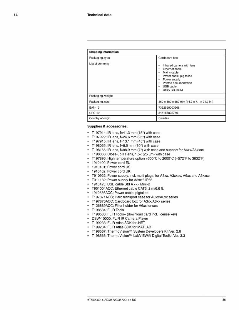
Packaging, type Cardboard box
List of contents • Infrared camera with lens• Ethernet cable• Mains cable• Power cable, pig-tailed• Power supply• Printed documentation• USB cable• Utility CD-ROM
Packaging, weight
Packaging, size 360 × 180 × 550 mm (14.2 × 7.1 × 21.7 in.)
EAN-13 7332558003268
UPC-12 845188002749
Country of origin Sweden
Supplies & accessories:
• T197914; IR lens, f=41.3 mm (15°) with case• T197922; IR lens, f=24.6 mm (25°) with case• T197915; IR lens, f=13.1 mm (45°) with case• T198065; IR lens, f=6.5 mm (80°) with case• T198165; IR lens, f=88.9 mm (7°) with case and support for A6xx/A6xxsc• T198066; Close-up IR lens, 1.5× (25 µm) with case• T197896; High temperature option +300°C to 2000°C (+572°F to 3632°F)• 1910400; Power cord EU• 1910401; Power cord US• 1910402; Power cord UK• T910922; Power supply, incl. multi plugs, for A3xx, A3xxsc, A6xx and A6xxsc• T911182; Power supply for A3xx f, IP66• 1910423; USB cable Std A <-> Mini-B• T951004ACC; Ethernet cable CAT6, 2 m/6.6 ft.• 1910586ACC; Power cable, pigtailed• T197871ACC; Hard transport case for A3xx/A6xx series• T197870ACC; Cardboard box for A3xx/A6xx series• T126889ACC; Filter holder for A6xx lenses• T198584; FLIR Tools• T198583; FLIR Tools+ (download card incl. license key)• DSW-10000; FLIR IR Camera Player• T199233; FLIR Atlas SDK for .NET• T199234; FLIR Atlas SDK for MATLAB• T198567; ThermoVision™ System Developers Kit Ver. 2.6• T198566; ThermoVision™ LabVIEW® Digital Toolkit Ver. 3.3
#T559950; r. AD/35720/35720; en-US 36
Technical data14
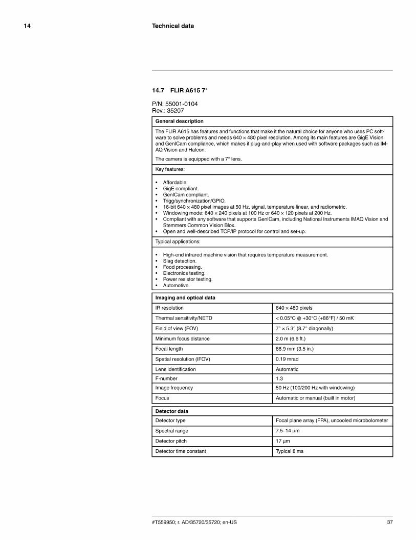
14.7 FLIR A615 7°
P/N: 55001-0104Rev.: 35207General description
The FLIR A615 has features and functions that make it the natural choice for anyone who uses PC soft-ware to solve problems and needs 640 × 480 pixel resolution. Among its main features are GigE Visionand GenICam compliance, which makes it plug-and-play when used with software packages such as IM-AQ Vision and Halcon.
The camera is equipped with a 7° lens.
Key features:
• Affordable.• GigE compliant.• GenICam compliant.• Trigg/synchronization/GPIO.• 16-bit 640 × 480 pixel images at 50 Hz, signal, temperature linear, and radiometric.• Windowing mode: 640 × 240 pixels at 100 Hz or 640 × 120 pixels at 200 Hz.• Compliant with any software that supports GenICam, including National Instruments IMAQ Vision and
Stemmers Common Vision Blox.• Open and well-described TCP/IP protocol for control and set-up.
Typical applications:
• High-end infrared machine vision that requires temperature measurement.• Slag detection.• Food processing.• Electronics testing.• Power resistor testing.• Automotive.
Imaging and optical data
IR resolution 640 × 480 pixels
Thermal sensitivity/NETD < 0.05°C @ +30°C (+86°F) / 50 mK
Field of view (FOV) 7° × 5.3° (8.7° diagonally)
Minimum focus distance 2.0 m (6.6 ft.)
Focal length 88.9 mm (3.5 in.)
Spatial resolution (IFOV) 0.19 mrad
Lens identification Automatic
F-number 1.3
Image frequency 50 Hz (100/200 Hz with windowing)
Focus Automatic or manual (built in motor)
Detector data
Detector type Focal plane array (FPA), uncooled microbolometer
Spectral range 7.5–14 µm
Detector pitch 17 µm
Detector time constant Typical 8 ms
#T559950; r. AD/35720/35720; en-US 37
Technical data14
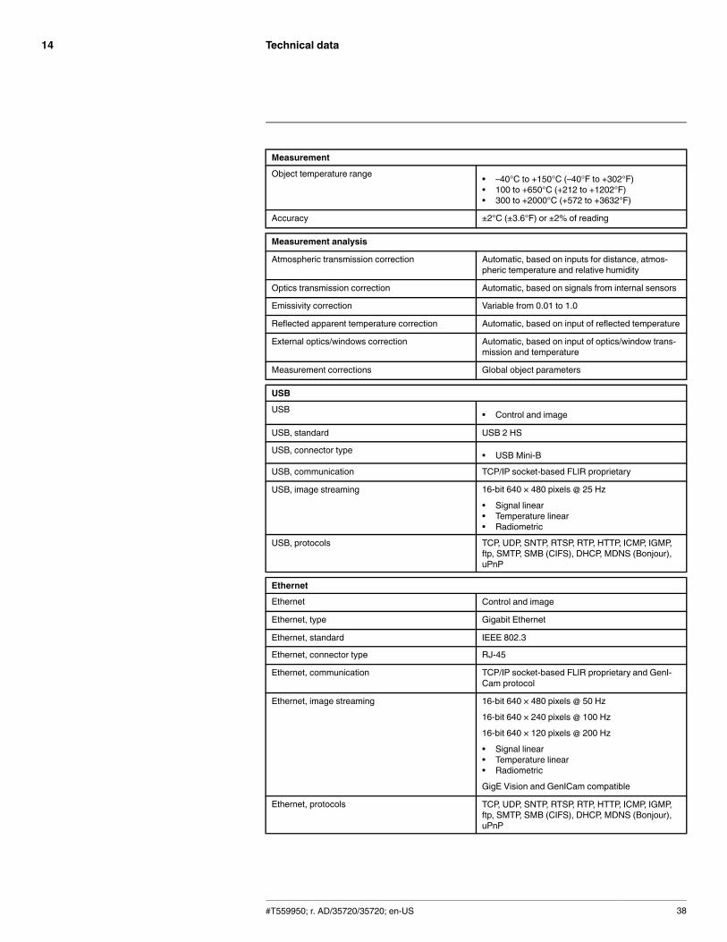
Measurement
Object temperature range • –40°C to +150°C (–40°F to +302°F)• 100 to +650°C (+212 to +1202°F)• 300 to +2000°C (+572 to +3632°F)
Accuracy ±2°C (±3.6°F) or ±2% of reading
Measurement analysis
Atmospheric transmission correction Automatic, based on inputs for distance, atmos-pheric temperature and relative humidity
Optics transmission correction Automatic, based on signals from internal sensors
Emissivity correction Variable from 0.01 to 1.0
Reflected apparent temperature correction Automatic, based on input of reflected temperature
External optics/windows correction Automatic, based on input of optics/window trans-mission and temperature
Measurement corrections Global object parameters
USB
USB • Control and image
USB, standard USB 2 HS
USB, connector type • USB Mini-B
USB, communication TCP/IP socket-based FLIR proprietary
USB, image streaming 16-bit 640 × 480 pixels @ 25 Hz
• Signal linear• Temperature linear• Radiometric
USB, protocols TCP, UDP, SNTP, RTSP, RTP, HTTP, ICMP, IGMP,ftp, SMTP, SMB (CIFS), DHCP, MDNS (Bonjour),uPnP
Ethernet
Ethernet Control and image
Ethernet, type Gigabit Ethernet
Ethernet, standard IEEE 802.3
Ethernet, connector type RJ-45
Ethernet, communication TCP/IP socket-based FLIR proprietary and GenI-Cam protocol
Ethernet, image streaming 16-bit 640 × 480 pixels @ 50 Hz
16-bit 640 × 240 pixels @ 100 Hz
16-bit 640 × 120 pixels @ 200 Hz
• Signal linear• Temperature linear• Radiometric
GigE Vision and GenICam compatible
Ethernet, protocols TCP, UDP, SNTP, RTSP, RTP, HTTP, ICMP, IGMP,ftp, SMTP, SMB (CIFS), DHCP, MDNS (Bonjour),uPnP
#T559950; r. AD/35720/35720; en-US 38
Technical data14
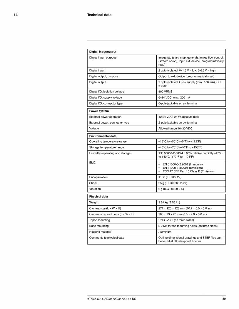
Digital input/output
Digital input, purpose Image tag (start, stop, general), Image flow control,(stream on/off), Input ext. device (programmaticallyread)
Digital input 2 opto-isolated, 0–1.5 V = low, 3–25 V = high
Digital output, purpose Output to ext. device (programmatically set)
Digital output 2 opto-isolated, ON = supply (max. 100 mA), OFF= open
Digital I/O, isolation voltage 500 VRMS
Digital I/O, supply voltage 6–24 VDC, max. 200 mA
Digital I/O, connector type 6-pole jackable screw terminal
Power system
External power operation 12/24 VDC, 24 W absolute max.
External power, connector type 2-pole jackable screw terminal
Voltage Allowed range 10–30 VDC
Environmental data
Operating temperature range –15°C to +50°C (+5°F to +122°F)
Storage temperature range –40°C to +70°C (–40°F to +158°F)
Humidity (operating and storage) IEC 60068-2-30/24 h 95% relative humidity +25°Cto +40°C (+77°F to +104°F)
EMC • EN 61000-6-2:2001 (Immunity)• EN 61000-6-3:2001 (Emission)• FCC 47 CFR Part 15 Class B (Emission)
Encapsulation IP 30 (IEC 60529)
Shock 25 g (IEC 60068-2-27)
Vibration 2 g (IEC 60068-2-6)
Physical data
Weight 1.61 kg (3.55 lb.)
Camera size (L × W × H) 271 × 126 × 128 mm (10.7 × 5.0 × 5.0 in.)
Camera size, excl. lens (L × W × H) 203 × 73 × 75 mm (8.0 × 2.9 × 3.0 in.)
Tripod mounting UNC ¼"-20 (on three sides)
Base mounting 2 × M4 thread mounting holes (on three sides)
Housing material Aluminum
Comments to physical data Outline dimensional drawings and STEP files canbe found at http://support.flir.com
#T559950; r. AD/35720/35720; en-US 39

Technical data14
Shipping information
Packaging, type Cardboard box
List of contents • Infrared camera with lens• Ethernet cable• Mains cable• Power cable, pig-tailed• Power supply• Printed documentation• USB cable• Utility CD-ROM
Packaging, weight 5.8 kg (12.8 lb.)
Packaging, size 400 × 400 × 540 mm (15.7 × 15.7 × 21.3 in.)
EAN-13 7332558004685
UPC-12 845188004620
Country of origin Sweden
Supplies & accessories:
• T197914; IR lens, f=41.3 mm (15°) with case• T197922; IR lens, f=24.6 mm (25°) with case• T197915; IR lens, f=13.1 mm (45°) with case• T198065; IR lens, f=6.5 mm (80°) with case• T198165; IR lens, f=88.9 mm (7°) with case and support for A6xx/A6xxsc• T197896; High temperature option +300°C to 2000°C (+572°F to 3632°F)• 1910400; Power cord EU• 1910401; Power cord US• 1910402; Power cord UK• T910922; Power supply, incl. multi plugs, for A3xx, A3xxsc, A6xx and A6xxsc• T911182; Power supply for A3xx f, IP66• 1910423; USB cable Std A <-> Mini-B• T951004ACC; Ethernet cable CAT6, 2 m/6.6 ft.• 1910586ACC; Power cable, pigtailed• T197871ACC; Hard transport case for A3xx/A6xx series• T197870ACC; Cardboard box for A3xx/A6xx series• T126889ACC; Filter holder for A6xx lenses• T198584; FLIR Tools• T198583; FLIR Tools+ (download card incl. license key)• DSW-10000; FLIR IR Camera Player• T199233; FLIR Atlas SDK for .NET• T199234; FLIR Atlas SDK for MATLAB• T198567; ThermoVision™ System Developers Kit Ver. 2.6• T198566; ThermoVision™ LabVIEW® Digital Toolkit Ver. 3.3
#T559950; r. AD/35720/35720; en-US 40
Technical data14
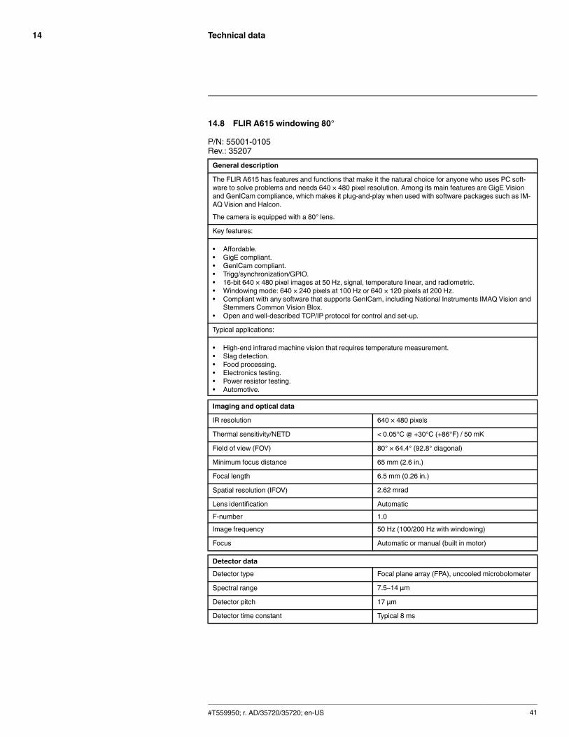
14.8 FLIR A615 windowing 80°
P/N: 55001-0105Rev.: 35207General description
The FLIR A615 has features and functions that make it the natural choice for anyone who uses PC soft-ware to solve problems and needs 640 × 480 pixel resolution. Among its main features are GigE Visionand GenICam compliance, which makes it plug-and-play when used with software packages such as IM-AQ Vision and Halcon.
The camera is equipped with a 80° lens.
Key features:
• Affordable.• GigE compliant.• GenICam compliant.• Trigg/synchronization/GPIO.• 16-bit 640 × 480 pixel images at 50 Hz, signal, temperature linear, and radiometric.• Windowing mode: 640 × 240 pixels at 100 Hz or 640 × 120 pixels at 200 Hz.• Compliant with any software that supports GenICam, including National Instruments IMAQ Vision and
Stemmers Common Vision Blox.• Open and well-described TCP/IP protocol for control and set-up.
Typical applications:
• High-end infrared machine vision that requires temperature measurement.• Slag detection.• Food processing.• Electronics testing.• Power resistor testing.• Automotive.
Imaging and optical data
IR resolution 640 × 480 pixels
Thermal sensitivity/NETD < 0.05°C @ +30°C (+86°F) / 50 mK
Field of view (FOV) 80° × 64.4° (92.8° diagonal)
Minimum focus distance 65 mm (2.6 in.)
Focal length 6.5 mm (0.26 in.)
Spatial resolution (IFOV) 2.62 mrad
Lens identification Automatic
F-number 1.0
Image frequency 50 Hz (100/200 Hz with windowing)
Focus Automatic or manual (built in motor)
Detector data
Detector type Focal plane array (FPA), uncooled microbolometer
Spectral range 7.5–14 µm
Detector pitch 17 µm
Detector time constant Typical 8 ms
#T559950; r. AD/35720/35720; en-US 41

Technical data14
Measurement
Object temperature range • –40°C to +150°C (–40°F to +302°F)• 100 to +650°C (+212 to +1202°F)• 300 to +2000°C (+572 to +3632°F)
Accuracy ±2°C (±3.6°F) or ±2% of reading
Measurement analysis
Atmospheric transmission correction Automatic, based on inputs for distance, atmos-pheric temperature and relative humidity
Optics transmission correction Automatic, based on signals from internal sensors
Emissivity correction Variable from 0.01 to 1.0
Reflected apparent temperature correction Automatic, based on input of reflected temperature
External optics/windows correction Automatic, based on input of optics/window trans-mission and temperature
Measurement corrections Global object parameters
USB
USB • Control and image
USB, standard USB 2 HS
USB, connector type • USB Mini-B
USB, communication TCP/IP socket-based FLIR proprietary
USB, image streaming 16-bit 640 × 480 pixels @ 25 Hz
• Signal linear• Temperature linear• Radiometric
USB, protocols TCP, UDP, SNTP, RTSP, RTP, HTTP, ICMP, IGMP,ftp, SMTP, SMB (CIFS), DHCP, MDNS (Bonjour),uPnP
Ethernet
Ethernet Control and image
Ethernet, type Gigabit Ethernet
Ethernet, standard IEEE 802.3
Ethernet, connector type RJ-45
Ethernet, communication TCP/IP socket-based FLIR proprietary and GenI-Cam protocol
Ethernet, image streaming 16-bit 640 × 480 pixels @ 50 Hz
16-bit 640 × 240 pixels @ 100 Hz
16-bit 640 × 120 pixels @ 200 Hz
• Signal linear• Temperature linear• Radiometric
GigE Vision and GenICam compatible
Ethernet, protocols TCP, UDP, SNTP, RTSP, RTP, HTTP, ICMP, IGMP,ftp, SMTP, SMB (CIFS), DHCP, MDNS (Bonjour),uPnP
#T559950; r. AD/35720/35720; en-US 42
Technical data14
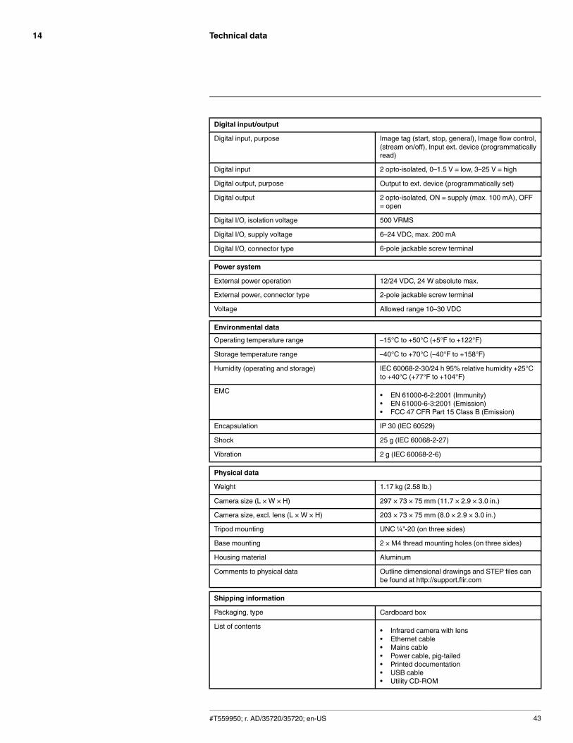
Digital input/output
Digital input, purpose Image tag (start, stop, general), Image flow control,(stream on/off), Input ext. device (programmaticallyread)
Digital input 2 opto-isolated, 0–1.5 V = low, 3–25 V = high
Digital output, purpose Output to ext. device (programmatically set)
Digital output 2 opto-isolated, ON = supply (max. 100 mA), OFF= open
Digital I/O, isolation voltage 500 VRMS
Digital I/O, supply voltage 6–24 VDC, max. 200 mA
Digital I/O, connector type 6-pole jackable screw terminal
Power system
External power operation 12/24 VDC, 24 W absolute max.
External power, connector type 2-pole jackable screw terminal
Voltage Allowed range 10–30 VDC
Environmental data
Operating temperature range –15°C to +50°C (+5°F to +122°F)
Storage temperature range –40°C to +70°C (–40°F to +158°F)
Humidity (operating and storage) IEC 60068-2-30/24 h 95% relative humidity +25°Cto +40°C (+77°F to +104°F)
EMC • EN 61000-6-2:2001 (Immunity)• EN 61000-6-3:2001 (Emission)• FCC 47 CFR Part 15 Class B (Emission)
Encapsulation IP 30 (IEC 60529)
Shock 25 g (IEC 60068-2-27)
Vibration 2 g (IEC 60068-2-6)
Physical data
Weight 1.17 kg (2.58 lb.)
Camera size (L × W × H) 297 × 73 × 75 mm (11.7 × 2.9 × 3.0 in.)
Camera size, excl. lens (L × W × H) 203 × 73 × 75 mm (8.0 × 2.9 × 3.0 in.)
Tripod mounting UNC ¼"-20 (on three sides)
Base mounting 2 × M4 thread mounting holes (on three sides)
Housing material Aluminum
Comments to physical data Outline dimensional drawings and STEP files canbe found at http://support.flir.com
Shipping information
Packaging, type Cardboard box
List of contents • Infrared camera with lens• Ethernet cable• Mains cable• Power cable, pig-tailed• Printed documentation• USB cable• Utility CD-ROM
#T559950; r. AD/35720/35720; en-US 43
Technical data14
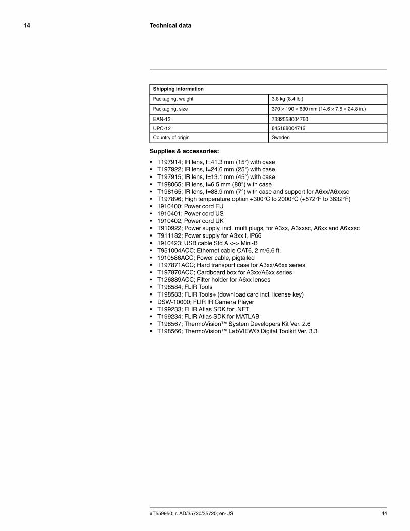
Shipping information
Packaging, weight 3.8 kg (8.4 lb.)
Packaging, size 370 × 190 × 630 mm (14.6 × 7.5 × 24.8 in.)
EAN-13 7332558004760
UPC-12 845188004712
Country of origin Sweden
Supplies & accessories:
• T197914; IR lens, f=41.3 mm (15°) with case• T197922; IR lens, f=24.6 mm (25°) with case• T197915; IR lens, f=13.1 mm (45°) with case• T198065; IR lens, f=6.5 mm (80°) with case• T198165; IR lens, f=88.9 mm (7°) with case and support for A6xx/A6xxsc• T197896; High temperature option +300°C to 2000°C (+572°F to 3632°F)• 1910400; Power cord EU• 1910401; Power cord US• 1910402; Power cord UK• T910922; Power supply, incl. multi plugs, for A3xx, A3xxsc, A6xx and A6xxsc• T911182; Power supply for A3xx f, IP66• 1910423; USB cable Std A <-> Mini-B• T951004ACC; Ethernet cable CAT6, 2 m/6.6 ft.• 1910586ACC; Power cable, pigtailed• T197871ACC; Hard transport case for A3xx/A6xx series• T197870ACC; Cardboard box for A3xx/A6xx series• T126889ACC; Filter holder for A6xx lenses• T198584; FLIR Tools• T198583; FLIR Tools+ (download card incl. license key)• DSW-10000; FLIR IR Camera Player• T199233; FLIR Atlas SDK for .NET• T199234; FLIR Atlas SDK for MATLAB• T198567; ThermoVision™ System Developers Kit Ver. 2.6• T198566; ThermoVision™ LabVIEW® Digital Toolkit Ver. 3.3
#T559950; r. AD/35720/35720; en-US 44

Technical data14
14.9 FLIR A655sc 15°
P/N: 55001-0301Rev.: 35207General description
The FLIR A655sc is an excellent choice for those working in R&D but don't need the highest frame ratesbut do require 640 × 480 pixel resolution. When using the camera in R&D, it is highly recommended touse the FLIR ResearchIR software from FLIR Systems.
The camera is equipped with a 15° lens.
Key features:
• Affordable.• 16-bit 640 × 480 pixel images at 25 Hz.• Start-and-stop recording in FLIR ResearchIR using digital input.• Windowing mode: 640 × 240 pixels at 100 Hz or 640 × 120 pixels at 200 Hz.
Typical applications:
• Mid- or high-end industrial R&D.
Imaging and optical data
IR resolution 640 × 480 pixels
Thermal sensitivity/NETD < 0.03°C @ +30°C (+86°F) / 30 mK
Field of view (FOV) 15° × 11° (19° diagonal)
Minimum focus distance 0.50 m (1.64 ft.)
Focal length 41.3 mm (1.63 in.)
Spatial resolution (IFOV) 0.41 mrad
Lens identification Automatic
F-number 1.0
Image frequency 50 Hz (100/200 Hz with windowing)
Focus Automatic or manual (built in motor)
Detector data
Detector type Focal plane array (FPA), uncooled microbolometer
Spectral range 7.5–14 µm
Detector pitch 17 µm
Detector time constant Typical 8 ms
Measurement
Object temperature range • –40°C to +150°C (–40°F to +302°F)• 100 to +650°C (+212 to +1202°F)
Accuracy ±2°C (±3.6°F) or ±2% of reading
Measurement analysis
Atmospheric transmission correction Automatic, based on inputs for distance, atmos-pheric temperature and relative humidity
Optics transmission correction Automatic, based on signals from internal sensors
Emissivity correction Variable from 0.01 to 1.0
Reflected apparent temperature correction Automatic, based on input of reflected temperature
#T559950; r. AD/35720/35720; en-US 45

Technical data14
Measurement analysis
External optics/windows correction Automatic, based on input of optics/window trans-mission and temperature
Measurement corrections Global object parameters
USB
USB • Control and image
USB, standard USB 2 HS
USB, connector type • USB Mini-B
USB, communication TCP/IP socket-based FLIR proprietary
USB, image streaming 16-bit 640 × 480 pixels @ 25 Hz
• Signal linear• Temperature linear• Radiometric
USB, protocols TCP, UDP, SNTP, RTSP, RTP, HTTP, ICMP, IGMP,ftp, SMTP, SMB (CIFS), DHCP, MDNS (Bonjour),uPnP
Ethernet
Ethernet Control and image
Ethernet, type Gigabit Ethernet
Ethernet, standard IEEE 802.3
Ethernet, connector type RJ-45
Ethernet, communication TCP/IP socket-based FLIR proprietary and GenI-Cam protocol
Ethernet, image streaming 16-bit 640 × 480 pixels @ 50 Hz
16-bit 640 × 240 pixels @ 100 Hz
16-bit 640 × 120 pixels @ 200 Hz
• Signal linear• Temperature linear• Radiometric
GigE Vision and GenICam compatible
Ethernet, protocols TCP, UDP, SNTP, RTSP, RTP, HTTP, ICMP, IGMP,ftp, SMTP, SMB (CIFS), DHCP, MDNS (Bonjour),uPnP
Digital input/output
Digital input, purpose Image tag (start, stop, general), Image flow control,(stream on/off), Input ext. device (programmaticallyread)
Digital input 2 opto-isolated, 0–1.5 V = low, 3–25 V = high
Digital output, purpose Output to ext. device (programmatically set)
Digital output 2 opto-isolated, ON = supply (max. 100 mA), OFF= open
Digital I/O, isolation voltage 500 VRMS
Digital I/O, supply voltage 6–24 VDC, max. 200 mA
Digital I/O, connector type 6-pole jackable screw terminal
#T559950; r. AD/35720/35720; en-US 46

Technical data14
Power system
External power operation 12/24 VDC, 24 W absolute max.
External power, connector type 2-pole jackable screw terminal
Voltage Allowed range 10–30 VDC
Environmental data
Operating temperature range –15°C to +50°C (+5°F to +122°F)
Storage temperature range –40°C to +70°C (–40°F to +158°F)
Humidity (operating and storage) IEC 60068-2-30/24 h 95% relative humidity +25°Cto +40°C (+77°F to +104°F)
EMC • EN 61000-6-2:2001 (Immunity)• EN 61000-6-3:2001 (Emission)• FCC 47 CFR Part 15 Class B (Emission)
Encapsulation IP 30 (IEC 60529)
Shock 25 g (IEC 60068-2-27)
Vibration 2 g (IEC 60068-2-6)
Physical data
Weight 0.92 kg (2.03 lb.)
Camera size (L × W × H) 222× 73 × 75 mm (8.7 × 2.9 × 3.0 in.)
Camera size, excl. lens (L × W × H) 203× 73 × 75 mm (8.0 × 2.9 × 3.0 in.)
Tripod mounting UNC ¼"-20 (on three sides)
Base mounting 2 × M4 thread mounting holes (on three sides)
Housing material Aluminum
Comments to physical data Outline dimensional drawings and STEP files canbe found at http://support.flir.com
Shipping information
Packaging, type Cardboard box
List of contents • Infrared camera with lens• Ethernet cable• FLIR ResearchIR Max 4 (licence only)• Hard transport case• Mains cable• Power cable, pig-tailed• Power supply• Printed documentation• USB cable
Packaging, weight
Packaging, size 360 × 180 × 550 mm (14.2 × 7.1 × 21.7 in.)
EAN-13 7332558003305
UPC-12 845188002787
Country of origin Sweden
Supplies & accessories:
• T197914; IR lens, f=41.3 mm (15°) with case• T197922; IR lens, f=24.6 mm (25°) with case• T197915; IR lens, f=13.1 mm (45°) with case
#T559950; r. AD/35720/35720; en-US 47

Technical data14
• T198065; IR lens, f=6.5 mm (80°) with case• T198165; IR lens, f=88.9 mm (7°) with case and support for A6xx/A6xxsc• T197896; High temperature option +300°C to 2000°C (+572°F to 3632°F)• 1910400; Power cord EU• 1910401; Power cord US• 1910402; Power cord UK• T910922; Power supply, incl. multi plugs, for A3xx, A3xxsc, A6xx and A6xxsc• T911182; Power supply for A3xx f, IP66• 1910423; USB cable Std A <-> Mini-B• T951004ACC; Ethernet cable CAT6, 2 m/6.6 ft.• 1910586ACC; Power cable, pigtailed• T197871ACC; Hard transport case for A3xx/A6xx series• T197870ACC; Cardboard box for A3xx/A6xx series• T126889ACC; Filter holder for A6xx lenses• T198584; FLIR Tools• T198583; FLIR Tools+ (download card incl. license key)• DSW-10000; FLIR IR Camera Player• T198697; FLIR ResearchIR Max + HSDR 4 (hardware sec. dev.)• T199014; FLIR ResearchIR Max + HSDR 4 (printed license key)• T199044; FLIR ResearchIR Max + HSDR 4 Upgrade (printed license key)• T198696; FLIR ResearchIR Max 4 (hardware sec. dev.)• T199013; FLIR ResearchIR Max 4 (printed license key)• T199043; FLIR ResearchIR Max 4 Upgrade (printed license key)• T198731; FLIR ResearchIR Standard 4 (hardware sec. dev.)• T199012; FLIR ResearchIR Standard 4 (printed license key)• T199042; FLIR ResearchIR Standard 4 Upgrade (printed license key)• T199233; FLIR Atlas SDK for .NET• T199234; FLIR Atlas SDK for MATLAB• T198567; ThermoVision™ System Developers Kit Ver. 2.6• T198566; ThermoVision™ LabVIEW® Digital Toolkit Ver. 3.3
#T559950; r. AD/35720/35720; en-US 48
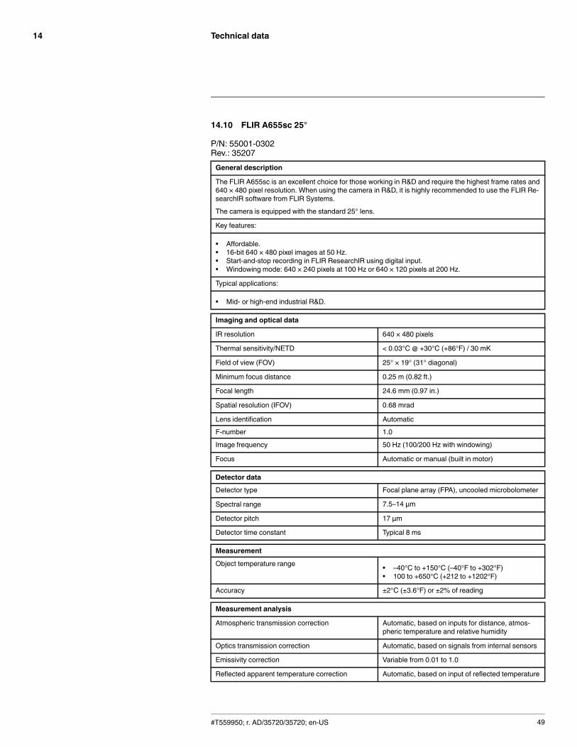
Technical data14
14.10 FLIR A655sc 25°
P/N: 55001-0302Rev.: 35207General description
The FLIR A655sc is an excellent choice for those working in R&D and require the highest frame rates and640 × 480 pixel resolution. When using the camera in R&D, it is highly recommended to use the FLIR Re-searchIR software from FLIR Systems.
The camera is equipped with the standard 25° lens.
Key features:
• Affordable.• 16-bit 640 × 480 pixel images at 50 Hz.• Start-and-stop recording in FLIR ResearchIR using digital input.• Windowing mode: 640 × 240 pixels at 100 Hz or 640 × 120 pixels at 200 Hz.
Typical applications:
• Mid- or high-end industrial R&D.
Imaging and optical data
IR resolution 640 × 480 pixels
Thermal sensitivity/NETD < 0.03°C @ +30°C (+86°F) / 30 mK
Field of view (FOV) 25° × 19° (31° diagonal)
Minimum focus distance 0.25 m (0.82 ft.)
Focal length 24.6 mm (0.97 in.)
Spatial resolution (IFOV) 0.68 mrad
Lens identification Automatic
F-number 1.0
Image frequency 50 Hz (100/200 Hz with windowing)
Focus Automatic or manual (built in motor)
Detector data
Detector type Focal plane array (FPA), uncooled microbolometer
Spectral range 7.5–14 µm
Detector pitch 17 µm
Detector time constant Typical 8 ms
Measurement
Object temperature range • –40°C to +150°C (–40°F to +302°F)• 100 to +650°C (+212 to +1202°F)
Accuracy ±2°C (±3.6°F) or ±2% of reading
Measurement analysis
Atmospheric transmission correction Automatic, based on inputs for distance, atmos-pheric temperature and relative humidity
Optics transmission correction Automatic, based on signals from internal sensors
Emissivity correction Variable from 0.01 to 1.0
Reflected apparent temperature correction Automatic, based on input of reflected temperature
#T559950; r. AD/35720/35720; en-US 49

Technical data14
Measurement analysis
External optics/windows correction Automatic, based on input of optics/window trans-mission and temperature
Measurement corrections Global object parameters
USB
USB • Control and image
USB, standard USB 2 HS
USB, connector type • USB Mini-B
USB, communication TCP/IP socket-based FLIR proprietary
USB, image streaming 16-bit 640 × 480 pixels @ 25 Hz
• Signal linear• Temperature linear• Radiometric
USB, protocols TCP, UDP, SNTP, RTSP, RTP, HTTP, ICMP, IGMP,ftp, SMTP, SMB (CIFS), DHCP, MDNS (Bonjour),uPnP
Ethernet
Ethernet Control and image
Ethernet, type Gigabit Ethernet
Ethernet, standard IEEE 802.3
Ethernet, connector type RJ-45
Ethernet, communication TCP/IP socket-based FLIR proprietary and GenI-Cam protocol
Ethernet, image streaming 16-bit 640 × 480 pixels @ 50 Hz
16-bit 640 × 240 pixels @ 100 Hz
16-bit 640 × 120 pixels @ 200 Hz
• Signal linear• Temperature linear• Radiometric
GigE Vision and GenICam compatible
Ethernet, protocols TCP, UDP, SNTP, RTSP, RTP, HTTP, ICMP, IGMP,ftp, SMTP, SMB (CIFS), DHCP, MDNS (Bonjour),uPnP
Digital input/output
Digital input, purpose Image tag (start, stop, general), Image flow control,(stream on/off), Input ext. device (programmaticallyread)
Digital input 2 opto-isolated, 0–1.5 V = low, 3–25 V = high
Digital output, purpose Output to ext. device (programmatically set)
Digital output 2 opto-isolated, ON = supply (max. 100 mA), OFF= open
Digital I/O, isolation voltage 500 VRMS
Digital I/O, supply voltage 6–24 VDC, max. 200 mA
Digital I/O, connector type 6-pole jackable screw terminal
#T559950; r. AD/35720/35720; en-US 50

Technical data14
Power system
External power operation 12/24 VDC, 24 W absolute max.
External power, connector type 2-pole jackable screw terminal
Voltage Allowed range 10–30 VDC
Environmental data
Operating temperature range –15°C to +50°C (+5°F to +122°F)
Storage temperature range –40°C to +70°C (–40°F to +158°F)
Humidity (operating and storage) IEC 60068-2-30/24 h 95% relative humidity +25°Cto +40°C (+77°F to +104°F)
EMC • EN 61000-6-2:2001 (Immunity)• EN 61000-6-3:2001 (Emission)• FCC 47 CFR Part 15 Class B (Emission)
Encapsulation IP 30 (IEC 60529)
Shock 25 g (IEC 60068-2-27)
Vibration 2 g (IEC 60068-2-6)
Physical data
Weight 0.90 kg (1.98 lb.)
Camera size (L × W × H) 216× 73 × 75 mm (8.5 × 2.9 × 3.0 in.)
Camera size, excl. lens (L × W × H) 203× 73 × 75 mm (8.0 × 2.9 × 3.0 in.)
Tripod mounting UNC ¼"-20 (on three sides)
Base mounting 2 × M4 thread mounting holes (on three sides)
Housing material Aluminum
Comments to physical data Outline dimensional drawings and STEP files canbe found at http://support.flir.com
Shipping information
Packaging, type Cardboard box
List of contents • Infrared camera with lens• Ethernet cable• FLIR ResearchIR Max 4 (licence only)• Hard transport case• Mains cable• Power cable, pig-tailed• Power supply• Printed documentation• USB cable
Packaging, weight 5.4 kg (11.9 lb.)
Packaging, size 360 × 180 × 550 mm (14.2 × 7.1 × 21.7 in.)
EAN-13 7332558003312
UPC-12 845188002794
Country of origin Sweden
Supplies & accessories:
• T197914; IR lens, f=41.3 mm (15°) with case• T197922; IR lens, f=24.6 mm (25°) with case• T197915; IR lens, f=13.1 mm (45°) with case
#T559950; r. AD/35720/35720; en-US 51
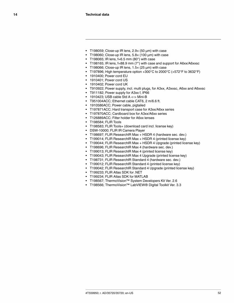
Technical data14
• T198059; Close-up IR lens, 2.9× (50 µm) with case• T198060; Close-up IR lens, 5.8× (100 µm) with case• T198065; IR lens, f=6.5 mm (80°) with case• T198165; IR lens, f=88.9 mm (7°) with case and support for A6xx/A6xxsc• T198066; Close-up IR lens, 1.5× (25 µm) with case• T197896; High temperature option +300°C to 2000°C (+572°F to 3632°F)• 1910400; Power cord EU• 1910401; Power cord US• 1910402; Power cord UK• T910922; Power supply, incl. multi plugs, for A3xx, A3xxsc, A6xx and A6xxsc• T911182; Power supply for A3xx f, IP66• 1910423; USB cable Std A <-> Mini-B• T951004ACC; Ethernet cable CAT6, 2 m/6.6 ft.• 1910586ACC; Power cable, pigtailed• T197871ACC; Hard transport case for A3xx/A6xx series• T197870ACC; Cardboard box for A3xx/A6xx series• T126889ACC; Filter holder for A6xx lenses• T198584; FLIR Tools• T198583; FLIR Tools+ (download card incl. license key)• DSW-10000; FLIR IR Camera Player• T198697; FLIR ResearchIR Max + HSDR 4 (hardware sec. dev.)• T199014; FLIR ResearchIR Max + HSDR 4 (printed license key)• T199044; FLIR ResearchIR Max + HSDR 4 Upgrade (printed license key)• T198696; FLIR ResearchIR Max 4 (hardware sec. dev.)• T199013; FLIR ResearchIR Max 4 (printed license key)• T199043; FLIR ResearchIR Max 4 Upgrade (printed license key)• T198731; FLIR ResearchIR Standard 4 (hardware sec. dev.)• T199012; FLIR ResearchIR Standard 4 (printed license key)• T199042; FLIR ResearchIR Standard 4 Upgrade (printed license key)• T199233; FLIR Atlas SDK for .NET• T199234; FLIR Atlas SDK for MATLAB• T198567; ThermoVision™ System Developers Kit Ver. 2.6• T198566; ThermoVision™ LabVIEW® Digital Toolkit Ver. 3.3
#T559950; r. AD/35720/35720; en-US 52

Technical data14
14.11 FLIR A655sc 45°
P/N: 55001-0303Rev.: 35207General description
The FLIR A655sc is an excellent choice for those working in R&D and require the highest frame rates and640 × 480 pixel resolution. When using the camera in R&D, it is highly recommended to use the FLIR Re-searchIR software from FLIR Systems.
The camera is equipped with a 45° lens.
Key features:
• Affordable.• 16-bit 640 × 480 pixel images at 50 Hz.• Start-and-stop recording in FLIR ResearchIR using digital input.• Windowing mode: 640 × 240 pixels at 100 Hz or 640 × 120 pixels at 200 Hz.
Typical applications:
• Mid- or high-end industrial R&D.
Imaging and optical data
IR resolution 640 × 480 pixels
Thermal sensitivity/NETD < 0.03°C @ +30°C (+86°F) / 30 mK
Field of view (FOV) 45° × 34° (55° diagonal)
Minimum focus distance 0.15 m (0.49 ft.)
Focal length 13.1 mm (0.52 in.)
Spatial resolution (IFOV) 1.23 mrad
Lens identification Automatic
F-number 1.0
Image frequency 50 Hz (100/200 Hz with windowing)
Focus Automatic or manual (built in motor)
Detector data
Detector type Focal plane array (FPA), uncooled microbolometer
Spectral range 7.5–14 µm
Detector pitch 17 µm
Detector time constant Typical 8 ms
Measurement
Object temperature range • –40°C to +150°C (–40°F to +302°F)• 100 to +650°C (+212 to +1202°F)
Accuracy ±2°C (±3.6°F) or ±2% of reading
Measurement analysis
Atmospheric transmission correction Automatic, based on inputs for distance, atmos-pheric temperature and relative humidity
Optics transmission correction Automatic, based on signals from internal sensors
Emissivity correction Variable from 0.01 to 1.0
Reflected apparent temperature correction Automatic, based on input of reflected temperature
#T559950; r. AD/35720/35720; en-US 53
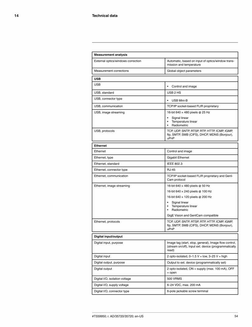
Technical data14
Measurement analysis
External optics/windows correction Automatic, based on input of optics/window trans-mission and temperature
Measurement corrections Global object parameters
USB
USB • Control and image
USB, standard USB 2 HS
USB, connector type • USB Mini-B
USB, communication TCP/IP socket-based FLIR proprietary
USB, image streaming 16-bit 640 × 480 pixels @ 25 Hz
• Signal linear• Temperature linear• Radiometric
USB, protocols TCP, UDP, SNTP, RTSP, RTP, HTTP, ICMP, IGMP,ftp, SMTP, SMB (CIFS), DHCP, MDNS (Bonjour),uPnP
Ethernet
Ethernet Control and image
Ethernet, type Gigabit Ethernet
Ethernet, standard IEEE 802.3
Ethernet, connector type RJ-45
Ethernet, communication TCP/IP socket-based FLIR proprietary and GenI-Cam protocol
Ethernet, image streaming 16-bit 640 × 480 pixels @ 50 Hz
16-bit 640 × 240 pixels @ 100 Hz
16-bit 640 × 120 pixels @ 200 Hz
• Signal linear• Temperature linear• Radiometric
GigE Vision and GenICam compatible
Ethernet, protocols TCP, UDP, SNTP, RTSP, RTP, HTTP, ICMP, IGMP,ftp, SMTP, SMB (CIFS), DHCP, MDNS (Bonjour),uPnP
Digital input/output
Digital input, purpose Image tag (start, stop, general), Image flow control,(stream on/off), Input ext. device (programmaticallyread)
Digital input 2 opto-isolated, 0–1.5 V = low, 3–25 V = high
Digital output, purpose Output to ext. device (programmatically set)
Digital output 2 opto-isolated, ON = supply (max. 100 mA), OFF= open
Digital I/O, isolation voltage 500 VRMS
Digital I/O, supply voltage 6–24 VDC, max. 200 mA
Digital I/O, connector type 6-pole jackable screw terminal
#T559950; r. AD/35720/35720; en-US 54
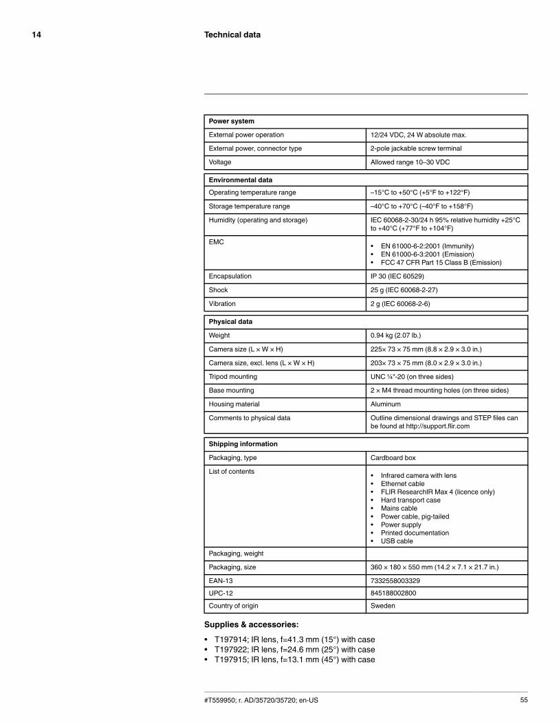
Technical data14
Power system
External power operation 12/24 VDC, 24 W absolute max.
External power, connector type 2-pole jackable screw terminal
Voltage Allowed range 10–30 VDC
Environmental data
Operating temperature range –15°C to +50°C (+5°F to +122°F)
Storage temperature range –40°C to +70°C (–40°F to +158°F)
Humidity (operating and storage) IEC 60068-2-30/24 h 95% relative humidity +25°Cto +40°C (+77°F to +104°F)
EMC • EN 61000-6-2:2001 (Immunity)• EN 61000-6-3:2001 (Emission)• FCC 47 CFR Part 15 Class B (Emission)
Encapsulation IP 30 (IEC 60529)
Shock 25 g (IEC 60068-2-27)
Vibration 2 g (IEC 60068-2-6)
Physical data
Weight 0.94 kg (2.07 lb.)
Camera size (L × W × H) 225× 73 × 75 mm (8.8 × 2.9 × 3.0 in.)
Camera size, excl. lens (L × W × H) 203× 73 × 75 mm (8.0 × 2.9 × 3.0 in.)
Tripod mounting UNC ¼"-20 (on three sides)
Base mounting 2 × M4 thread mounting holes (on three sides)
Housing material Aluminum
Comments to physical data Outline dimensional drawings and STEP files canbe found at http://support.flir.com
Shipping information
Packaging, type Cardboard box
List of contents • Infrared camera with lens• Ethernet cable• FLIR ResearchIR Max 4 (licence only)• Hard transport case• Mains cable• Power cable, pig-tailed• Power supply• Printed documentation• USB cable
Packaging, weight
Packaging, size 360 × 180 × 550 mm (14.2 × 7.1 × 21.7 in.)
EAN-13 7332558003329
UPC-12 845188002800
Country of origin Sweden
Supplies & accessories:
• T197914; IR lens, f=41.3 mm (15°) with case• T197922; IR lens, f=24.6 mm (25°) with case• T197915; IR lens, f=13.1 mm (45°) with case
#T559950; r. AD/35720/35720; en-US 55
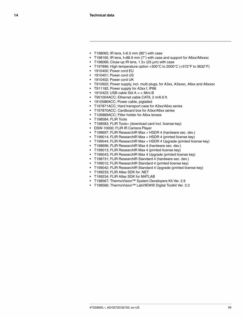
Technical data14
• T198065; IR lens, f=6.5 mm (80°) with case• T198165; IR lens, f=88.9 mm (7°) with case and support for A6xx/A6xxsc• T198066; Close-up IR lens, 1.5× (25 µm) with case• T197896; High temperature option +300°C to 2000°C (+572°F to 3632°F)• 1910400; Power cord EU• 1910401; Power cord US• 1910402; Power cord UK• T910922; Power supply, incl. multi plugs, for A3xx, A3xxsc, A6xx and A6xxsc• T911182; Power supply for A3xx f, IP66• 1910423; USB cable Std A <-> Mini-B• T951004ACC; Ethernet cable CAT6, 2 m/6.6 ft.• 1910586ACC; Power cable, pigtailed• T197871ACC; Hard transport case for A3xx/A6xx series• T197870ACC; Cardboard box for A3xx/A6xx series• T126889ACC; Filter holder for A6xx lenses• T198584; FLIR Tools• T198583; FLIR Tools+ (download card incl. license key)• DSW-10000; FLIR IR Camera Player• T198697; FLIR ResearchIR Max + HSDR 4 (hardware sec. dev.)• T199014; FLIR ResearchIR Max + HSDR 4 (printed license key)• T199044; FLIR ResearchIR Max + HSDR 4 Upgrade (printed license key)• T198696; FLIR ResearchIR Max 4 (hardware sec. dev.)• T199013; FLIR ResearchIR Max 4 (printed license key)• T199043; FLIR ResearchIR Max 4 Upgrade (printed license key)• T198731; FLIR ResearchIR Standard 4 (hardware sec. dev.)• T199012; FLIR ResearchIR Standard 4 (printed license key)• T199042; FLIR ResearchIR Standard 4 Upgrade (printed license key)• T199233; FLIR Atlas SDK for .NET• T199234; FLIR Atlas SDK for MATLAB• T198567; ThermoVision™ System Developers Kit Ver. 2.6• T198566; ThermoVision™ LabVIEW® Digital Toolkit Ver. 3.3
#T559950; r. AD/35720/35720; en-US 56
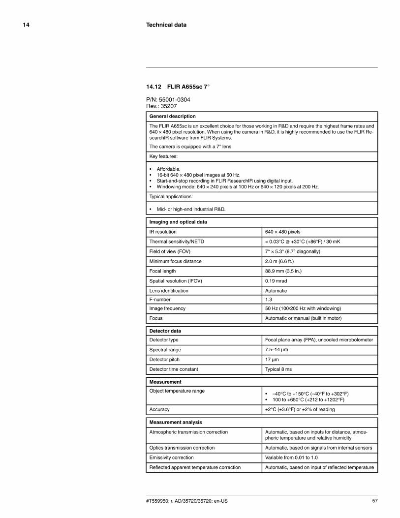
Technical data14
14.12 FLIR A655sc 7°
P/N: 55001-0304Rev.: 35207General description
The FLIR A655sc is an excellent choice for those working in R&D and require the highest frame rates and640 × 480 pixel resolution. When using the camera in R&D, it is highly recommended to use the FLIR Re-searchIR software from FLIR Systems.
The camera is equipped with a 7° lens.
Key features:
• Affordable.• 16-bit 640 × 480 pixel images at 50 Hz.• Start-and-stop recording in FLIR ResearchIR using digital input.• Windowing mode: 640 × 240 pixels at 100 Hz or 640 × 120 pixels at 200 Hz.
Typical applications:
• Mid- or high-end industrial R&D.
Imaging and optical data
IR resolution 640 × 480 pixels
Thermal sensitivity/NETD < 0.03°C @ +30°C (+86°F) / 30 mK
Field of view (FOV) 7° × 5.3° (8.7° diagonally)
Minimum focus distance 2.0 m (6.6 ft.)
Focal length 88.9 mm (3.5 in.)
Spatial resolution (IFOV) 0.19 mrad
Lens identification Automatic
F-number 1.3
Image frequency 50 Hz (100/200 Hz with windowing)
Focus Automatic or manual (built in motor)
Detector data
Detector type Focal plane array (FPA), uncooled microbolometer
Spectral range 7.5–14 µm
Detector pitch 17 µm
Detector time constant Typical 8 ms
Measurement
Object temperature range • –40°C to +150°C (–40°F to +302°F)• 100 to +650°C (+212 to +1202°F)
Accuracy ±2°C (±3.6°F) or ±2% of reading
Measurement analysis
Atmospheric transmission correction Automatic, based on inputs for distance, atmos-pheric temperature and relative humidity
Optics transmission correction Automatic, based on signals from internal sensors
Emissivity correction Variable from 0.01 to 1.0
Reflected apparent temperature correction Automatic, based on input of reflected temperature
#T559950; r. AD/35720/35720; en-US 57

Technical data14
Measurement analysis
External optics/windows correction Automatic, based on input of optics/window trans-mission and temperature
Measurement corrections Global object parameters
USB
USB • Control and image
USB, standard USB 2 HS
USB, connector type • USB Mini-B
USB, communication TCP/IP socket-based FLIR proprietary
USB, image streaming 16-bit 640 × 480 pixels @ 25 Hz
• Signal linear• Temperature linear• Radiometric
USB, protocols TCP, UDP, SNTP, RTSP, RTP, HTTP, ICMP, IGMP,ftp, SMTP, SMB (CIFS), DHCP, MDNS (Bonjour),uPnP
Ethernet
Ethernet Control and image
Ethernet, type Gigabit Ethernet
Ethernet, standard IEEE 802.3
Ethernet, connector type RJ-45
Ethernet, communication TCP/IP socket-based FLIR proprietary and GenI-Cam protocol
Ethernet, image streaming 16-bit 640 × 480 pixels @ 50 Hz
16-bit 640 × 240 pixels @ 100 Hz
16-bit 640 × 120 pixels @ 200 Hz
• Signal linear• Temperature linear• Radiometric
GigE Vision and GenICam compatible
Ethernet, protocols TCP, UDP, SNTP, RTSP, RTP, HTTP, ICMP, IGMP,ftp, SMTP, SMB (CIFS), DHCP, MDNS (Bonjour),uPnP
Digital input/output
Digital input, purpose Image tag (start, stop, general), Image flow control,(stream on/off), Input ext. device (programmaticallyread)
Digital input 2 opto-isolated, 0–1.5 V = low, 3–25 V = high
Digital output, purpose Output to ext. device (programmatically set)
Digital output 2 opto-isolated, ON = supply (max. 100 mA), OFF= open
Digital I/O, isolation voltage 500 VRMS
Digital I/O, supply voltage 6–24 VDC, max. 200 mA
Digital I/O, connector type 6-pole jackable screw terminal
#T559950; r. AD/35720/35720; en-US 58

Technical data14
Power system
External power operation 12/24 VDC, 24 W absolute max.
External power, connector type 2-pole jackable screw terminal
Voltage Allowed range 10–30 VDC
Environmental data
Operating temperature range –15°C to +50°C (+5°F to +122°F)
Storage temperature range –40°C to +70°C (–40°F to +158°F)
Humidity (operating and storage) IEC 60068-2-30/24 h 95% relative humidity +25°Cto +40°C (+77°F to +104°F)
EMC • EN 61000-6-2:2001 (Immunity)• EN 61000-6-3:2001 (Emission)• FCC 47 CFR Part 15 Class B (Emission)
Encapsulation IP 30 (IEC 60529)
Shock 25 g (IEC 60068-2-27)
Vibration 2 g (IEC 60068-2-6)
Physical data
Weight 1.61 kg (3.55 lb.)
Camera size (L × W × H) 271× 126 × 128 mm (10.7 × 5.0 × 5.0 in.)
Camera size, excl. lens (L × W × H) 203× 73 × 75 mm (8.0 × 2.9 × 3.0 in.)
Tripod mounting UNC ¼"-20 (on three sides)
Base mounting 2 × M4 thread mounting holes (on three sides)
Housing material Aluminum
Comments to physical data Outline dimensional drawings and STEP files canbe found at http://support.flir.com
Shipping information
Packaging, type Cardboard box
List of contents • Infrared camera with lens• Ethernet cable• FLIR ResearchIR Max 4 (licence only)• Hard transport case• Mains cable• Power cable, pig-tailed• Power supply• Printed documentation• USB cable
Packaging, weight
Packaging, size
EAN-13 7332558004715
UPC-12 845188004651
Country of origin Sweden
Supplies & accessories:
• T197914; IR lens, f=41.3 mm (15°) with case• T197922; IR lens, f=24.6 mm (25°) with case• T197915; IR lens, f=13.1 mm (45°) with case
#T559950; r. AD/35720/35720; en-US 59
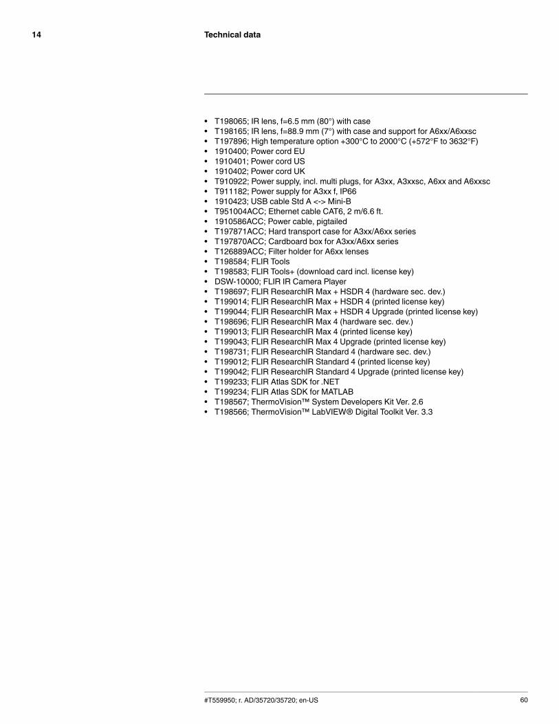
Technical data14
• T198065; IR lens, f=6.5 mm (80°) with case• T198165; IR lens, f=88.9 mm (7°) with case and support for A6xx/A6xxsc• T197896; High temperature option +300°C to 2000°C (+572°F to 3632°F)• 1910400; Power cord EU• 1910401; Power cord US• 1910402; Power cord UK• T910922; Power supply, incl. multi plugs, for A3xx, A3xxsc, A6xx and A6xxsc• T911182; Power supply for A3xx f, IP66• 1910423; USB cable Std A <-> Mini-B• T951004ACC; Ethernet cable CAT6, 2 m/6.6 ft.• 1910586ACC; Power cable, pigtailed• T197871ACC; Hard transport case for A3xx/A6xx series• T197870ACC; Cardboard box for A3xx/A6xx series• T126889ACC; Filter holder for A6xx lenses• T198584; FLIR Tools• T198583; FLIR Tools+ (download card incl. license key)• DSW-10000; FLIR IR Camera Player• T198697; FLIR ResearchIR Max + HSDR 4 (hardware sec. dev.)• T199014; FLIR ResearchIR Max + HSDR 4 (printed license key)• T199044; FLIR ResearchIR Max + HSDR 4 Upgrade (printed license key)• T198696; FLIR ResearchIR Max 4 (hardware sec. dev.)• T199013; FLIR ResearchIR Max 4 (printed license key)• T199043; FLIR ResearchIR Max 4 Upgrade (printed license key)• T198731; FLIR ResearchIR Standard 4 (hardware sec. dev.)• T199012; FLIR ResearchIR Standard 4 (printed license key)• T199042; FLIR ResearchIR Standard 4 Upgrade (printed license key)• T199233; FLIR Atlas SDK for .NET• T199234; FLIR Atlas SDK for MATLAB• T198567; ThermoVision™ System Developers Kit Ver. 2.6• T198566; ThermoVision™ LabVIEW® Digital Toolkit Ver. 3.3
#T559950; r. AD/35720/35720; en-US 60

Technical data14
14.13 FLIR A655sc 80°
P/N: 55001-0305Rev.: 35207General description
The FLIR A655sc is an excellent choice for those working in R&D and require the highest frame rates and640 × 480 pixel resolution. When using the camera in R&D, it is highly recommended to use the FLIR Re-searchIR software from FLIR Systems.
The camera is equipped with a 80° lens.
Key features:
• Affordable.• 16-bit 640 × 480 pixel images at 50 Hz.• Start-and-stop recording in FLIR ResearchIR using digital input.• Windowing mode: 640 × 240 pixels at 100 Hz or 640 × 120 pixels at 200 Hz.
Typical applications:
• Mid- or high-end industrial R&D.
Imaging and optical data
IR resolution 640 × 480 pixels
Thermal sensitivity/NETD < 0.03°C @ +30°C (+86°F) / 30 mK
Field of view (FOV) 80° × 64.4° (92.8° diagonal)
Minimum focus distance 65 mm (2.6 in.)
Focal length 6.5 mm (0.26 in.)
Spatial resolution (IFOV) 2.62 mrad
Lens identification Automatic
F-number 1.0
Image frequency 50 Hz (100/200 Hz with windowing)
Focus Automatic or manual (built in motor)
Detector data
Detector type Focal plane array (FPA), uncooled microbolometer
Spectral range 7.5–14 µm
Detector pitch 17 µm
Detector time constant Typical 8 ms
Measurement
Object temperature range • –40°C to +150°C (–40°F to +302°F)• 100 to +650°C (+212 to +1202°F)
Accuracy ±2°C (±3.6°F) or ±2% of reading
Measurement analysis
Atmospheric transmission correction Automatic, based on inputs for distance, atmos-pheric temperature and relative humidity
Optics transmission correction Automatic, based on signals from internal sensors
Emissivity correction Variable from 0.01 to 1.0
Reflected apparent temperature correction Automatic, based on input of reflected temperature
#T559950; r. AD/35720/35720; en-US 61

Technical data14
Measurement analysis
External optics/windows correction Automatic, based on input of optics/window trans-mission and temperature
Measurement corrections Global object parameters
USB
USB • Control and image
USB, standard USB 2 HS
USB, connector type • USB Mini-B
USB, communication TCP/IP socket-based FLIR proprietary
USB, image streaming 16-bit 640 × 480 pixels @ 25 Hz
• Signal linear• Temperature linear• Radiometric
USB, protocols TCP, UDP, SNTP, RTSP, RTP, HTTP, ICMP, IGMP,ftp, SMTP, SMB (CIFS), DHCP, MDNS (Bonjour),uPnP
Ethernet
Ethernet Control and image
Ethernet, type Gigabit Ethernet
Ethernet, standard IEEE 802.3
Ethernet, connector type RJ-45
Ethernet, communication TCP/IP socket-based FLIR proprietary and GenI-Cam protocol
Ethernet, image streaming 16-bit 640 × 480 pixels @ 50 Hz
16-bit 640 × 240 pixels @ 100 Hz
16-bit 640 × 120 pixels @ 200 Hz
• Signal linear• Temperature linear• Radiometric
GigE Vision and GenICam compatible
Ethernet, protocols TCP, UDP, SNTP, RTSP, RTP, HTTP, ICMP, IGMP,ftp, SMTP, SMB (CIFS), DHCP, MDNS (Bonjour),uPnP
Digital input/output
Digital input, purpose Image tag (start, stop, general), Image flow control,(stream on/off), Input ext. device (programmaticallyread)
Digital input 2 opto-isolated, 0–1.5 V = low, 3–25 V = high
Digital output, purpose Output to ext. device (programmatically set)
Digital output 2 opto-isolated, ON = supply (max. 100 mA), OFF= open
Digital I/O, isolation voltage 500 VRMS
Digital I/O, supply voltage 6–24 VDC, max. 200 mA
Digital I/O, connector type 6-pole jackable screw terminal
#T559950; r. AD/35720/35720; en-US 62

Technical data14
Power system
External power operation 12/24 VDC, 24 W absolute max.
External power, connector type 2-pole jackable screw terminal
Voltage Allowed range 10–30 VDC
Environmental data
Operating temperature range –15°C to +50°C (+5°F to +122°F)
Storage temperature range –40°C to +70°C (–40°F to +158°F)
Humidity (operating and storage) IEC 60068-2-30/24 h 95% relative humidity +25°Cto +40°C (+77°F to +104°F)
EMC • EN 61000-6-2:2001 (Immunity)• EN 61000-6-3:2001 (Emission)• FCC 47 CFR Part 15 Class B (Emission)
Encapsulation IP 30 (IEC 60529)
Shock 25 g (IEC 60068-2-27)
Vibration 2 g (IEC 60068-2-6)
Physical data
Weight 1.17 kg (2.58 lb.)
Camera size (L × W × H) 297 × 73 × 75 mm (11.7 × 2.9 × 3.0 in.)
Camera size, excl. lens (L × W × H) 203× 73 × 75 mm (8.0 × 2.9 × 3.0 in.)
Tripod mounting UNC ¼"-20 (on three sides)
Base mounting 2 × M4 thread mounting holes (on three sides)
Housing material Aluminum
Comments to physical data Outline dimensional drawings and STEP files canbe found at http://support.flir.com
Shipping information
Packaging, type Cardboard box
List of contents • Infrared camera with lens• Ethernet cable• FLIR ResearchIR Max 4 (licence only)• Hard transport case• Mains cable• Power cable, pig-tailed• Power supply• Printed documentation• USB cable
Packaging, weight
Packaging, size
EAN-13 7332558006054
UPC-12 845188006266
Country of origin Sweden
Supplies & accessories:
• T197914; IR lens, f=41.3 mm (15°) with case• T197922; IR lens, f=24.6 mm (25°) with case• T197915; IR lens, f=13.1 mm (45°) with case
#T559950; r. AD/35720/35720; en-US 63

Technical data14
• T198065; IR lens, f=6.5 mm (80°) with case• T198165; IR lens, f=88.9 mm (7°) with case and support for A6xx/A6xxsc• T197896; High temperature option +300°C to 2000°C (+572°F to 3632°F)• 1910400; Power cord EU• 1910401; Power cord US• 1910402; Power cord UK• T910922; Power supply, incl. multi plugs, for A3xx, A3xxsc, A6xx and A6xxsc• T911182; Power supply for A3xx f, IP66• 1910423; USB cable Std A <-> Mini-B• T951004ACC; Ethernet cable CAT6, 2 m/6.6 ft.• 1910586ACC; Power cable, pigtailed• T197871ACC; Hard transport case for A3xx/A6xx series• T197870ACC; Cardboard box for A3xx/A6xx series• T126889ACC; Filter holder for A6xx lenses• T198584; FLIR Tools• T198583; FLIR Tools+ (download card incl. license key)• DSW-10000; FLIR IR Camera Player• T198697; FLIR ResearchIR Max + HSDR 4 (hardware sec. dev.)• T199014; FLIR ResearchIR Max + HSDR 4 (printed license key)• T199044; FLIR ResearchIR Max + HSDR 4 Upgrade (printed license key)• T198696; FLIR ResearchIR Max 4 (hardware sec. dev.)• T199013; FLIR ResearchIR Max 4 (printed license key)• T199043; FLIR ResearchIR Max 4 Upgrade (printed license key)• T198731; FLIR ResearchIR Standard 4 (hardware sec. dev.)• T199012; FLIR ResearchIR Standard 4 (printed license key)• T199042; FLIR ResearchIR Standard 4 Upgrade (printed license key)• T199233; FLIR Atlas SDK for .NET• T199234; FLIR Atlas SDK for MATLAB• T198567; ThermoVision™ System Developers Kit Ver. 2.6• T198566; ThermoVision™ LabVIEW® Digital Toolkit Ver. 3.3
#T559950; r. AD/35720/35720; en-US 64
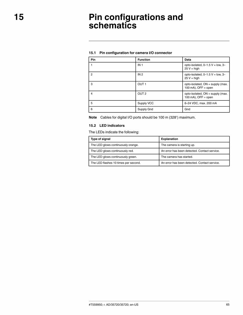
Pin configurations andschematics
15
15.1 Pin configuration for camera I/O connector
Pin Function Data1 IN 1 opto-isolated, 0–1.5 V = low, 3–
25 V = high
2 IN 2 opto-isolated, 0–1.5 V = low, 3–25 V = high
3 OUT 1 opto-isolated, ON = supply (max.100 mA), OFF = open
4 OUT 2 opto-isolated, ON = supply (max.100 mA), OFF = open
5 Supply VCC 6–24 VDC, max. 200 mA
6 Supply Gnd Gnd
Note Cables for digital I/O ports should be 100 m (328′) maximum.
15.2 LED indicators
The LEDs indicate the following:
Type of signal Explanation
The LED glows continuously orange. The camera is starting up.
The LED glows continuously red. An error has been detected. Contact service.
The LED glows continuously green. The camera has started.
The LED flashes 10 times per second. An error has been detected. Contact service.
#T559950; r. AD/35720/35720; en-US 65

Mechanical drawings16
#T559950; r. AD/35720/35720; en-US 66
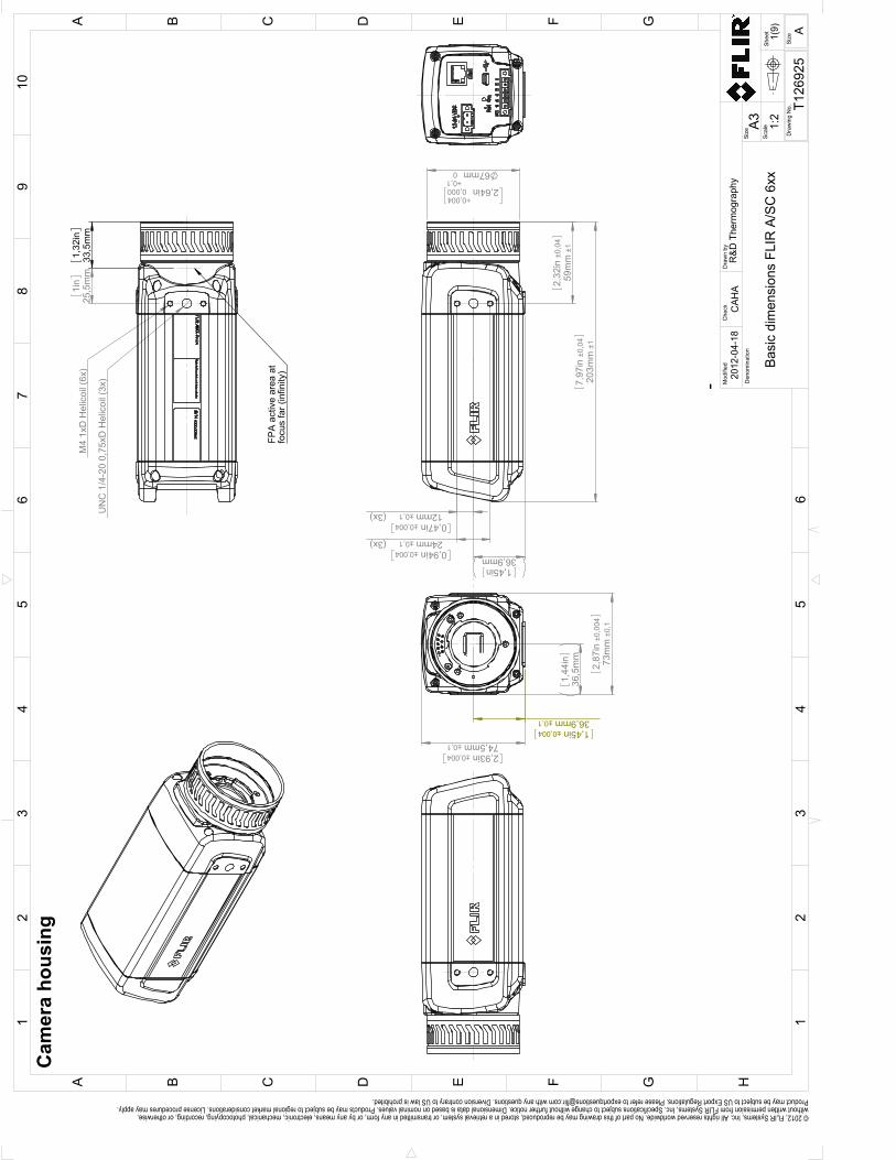
12mm±0,1 (3x)0,47in±0,004
24mm±0,1 (3x)0,94in±0,004
59m
m±1
2,32
in±0
,04
203m
m±1
7,97
in±0
,04
67mm0+0,1
2,64in0,000+0,004
36,9mm1,45in
73m
m±0
,12,
87in
±0,0
04
36,5
mm
1,44
in
36,9mm±0,11,45in±0,004
74,5mm±0,12,93in±0,004
UN
C 1
/4-2
0 0,
75xD
Hel
icoi
l (3x
)
M4
1xD
Hel
icoi
l (6x
)
1,32
in33
,5m
m
1i
n25
,5m
m
FPA
act
ive
area
at
focu
s fa
r (in
finity
)
Cam
era
hous
ing
Shee
t
Dra
win
g N
o.
Size
Che
ckD
raw
n by
Den
omin
atio
nA3
1(9)
T126
925
Basi
c di
men
sion
s FL
IR A
/SC
6xx
CAH
A20
12-0
4-18
R&D
The
rmog
raph
yM
odifi
ed
12
34
56
78
910
A B C D E F G H
13
25
4
C FB D GEA
6Si
ze
A
1:2
Scal
e
© 2012, FLIR Systems, Inc. All rights reserved worldwide. No part of this drawing may be reproduced, stored in a retrieval system, or transmitted in any form, or by any means, electronic, mechanical, photocopying, recording, or otherwise, without written permission from FLIR Systems, Inc. Specifications subject to change without further notice. Dimensional data is based on nominal values. Products may be subject to regional market considerations. License procedures may apply. Product may be subject to US Export Regulations. Please refer to [email protected] with any questions. Diversion contrary to US law is prohibited.
-
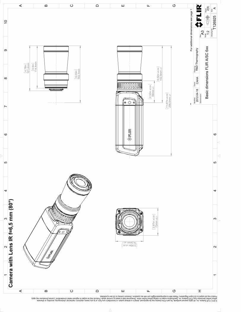
2,
87in
±0,
0073
mm
±0,
1
2,93in ±0,0074,5mm ±0,1
11
,67i
n ±0
,04
296,
5mm
±1
2,
32in
±0,
0459
mm
±1
6,
02in
±0,
0415
2,9m
m ±
1
4,
5in
114,
4mm
4,
78in
121,
4mm
6,
03in
153,
1mm
Cam
era
with
Len
s IR
f=6,
5 m
m (8
0°)
For a
dditi
onal
dim
ensi
ons
see
page
1
Shee
t
Dra
win
g N
o.
Size
Che
ckD
raw
n by
Den
omin
atio
nA3
2(9)
T126
925
Basi
c di
men
sion
s FL
IR A
/SC
6xx
CAH
A20
12-0
4-18
R&D
The
rmog
raph
yM
odifi
ed
12
34
56
78
910
A B C D E F G H
13
25
4
C FB D GEA
6Si
ze
A
1:2
Scal
e
© 2012, FLIR Systems, Inc. All rights reserved worldwide. No part of this drawing may be reproduced, stored in a retrieval system, or transmitted in any form, or by any means, electronic, mechanical, photocopying, recording, or otherwise, without written permission from FLIR Systems, Inc. Specifications subject to change without further notice. Dimensional data is based on nominal values. Products may be subject to regional market considerations. License procedures may apply. Product may be subject to US Export Regulations. Please refer to [email protected] with any questions. Diversion contrary to US law is prohibited.
-

59m
m±1
2,32
in±0
,04
81m
m±1
3,19
in±0
,04
224,
5mm
±18,
84in
±0,0
4
67mm±0,12,64in±0,004
73m
m±0
,12,
87in
±0,0
04
74,5mm±0,12,93in±0,004
49,3
mm
1,94
in
42,3
mm
1,66
in
81m
m3,
19in
Cam
era
with
Len
s IR
f=13
,1 m
m (4
5°)
For a
dditi
onal
dim
ensi
ons
see
page
1
Shee
t
Dra
win
g N
o.
Size
Che
ckD
raw
n by
Den
omin
atio
nA3
3(9)
T126
925
Basi
c di
men
sion
s FL
IR A
/SC
6xx
CAH
A20
12-0
4-18
R&D
The
rmog
raph
yM
odifi
ed
12
34
56
78
910
A B C D E F G H
13
25
4
C FB D GEA
6Si
ze
A
1:2
Scal
e
© 2012, FLIR Systems, Inc. All rights reserved worldwide. No part of this drawing may be reproduced, stored in a retrieval system, or transmitted in any form, or by any means, electronic, mechanical, photocopying, recording, or otherwise, without written permission from FLIR Systems, Inc. Specifications subject to change without further notice. Dimensional data is based on nominal values. Products may be subject to regional market considerations. License procedures may apply. Product may be subject to US Export Regulations. Please refer to [email protected] with any questions. Diversion contrary to US law is prohibited.
-
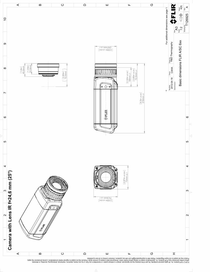
59m
m±1
2,32
in±0
,04
72,5
mm
±12,
85in
±0,0
4
67mm±0,12,64in±0,004
216m
m±1
8,5i
n±0
,04
73m
m±0
,12,
87in
±0,0
04
74,5mm±0,12,93in±0,004
40,8
mm
1,6i
n
33,8
mm
1,33
in
72,5
mm
2,85
in
Cam
era
with
Len
s IR
f=24
,6 m
m (2
5°)
For a
dditi
onal
dim
ensi
ons
see
page
1
Shee
t
Dra
win
g N
o.
Size
Che
ckD
raw
n by
Den
omin
atio
nA3
4(9)
T126
925
Basi
c di
men
sion
s FL
IR A
/SC
6xx
CAH
A20
12-0
4-18
R&D
The
rmog
raph
yM
odifi
ed
12
34
56
78
910
A B C D E F G H
13
25
4
C FB D GEA
6Si
ze
A
1:2
Scal
e
© 2012, FLIR Systems, Inc. All rights reserved worldwide. No part of this drawing may be reproduced, stored in a retrieval system, or transmitted in any form, or by any means, electronic, mechanical, photocopying, recording, or otherwise, without written permission from FLIR Systems, Inc. Specifications subject to change without further notice. Dimensional data is based on nominal values. Products may be subject to regional market considerations. License procedures may apply. Product may be subject to US Export Regulations. Please refer to [email protected] with any questions. Diversion contrary to US law is prohibited.
-
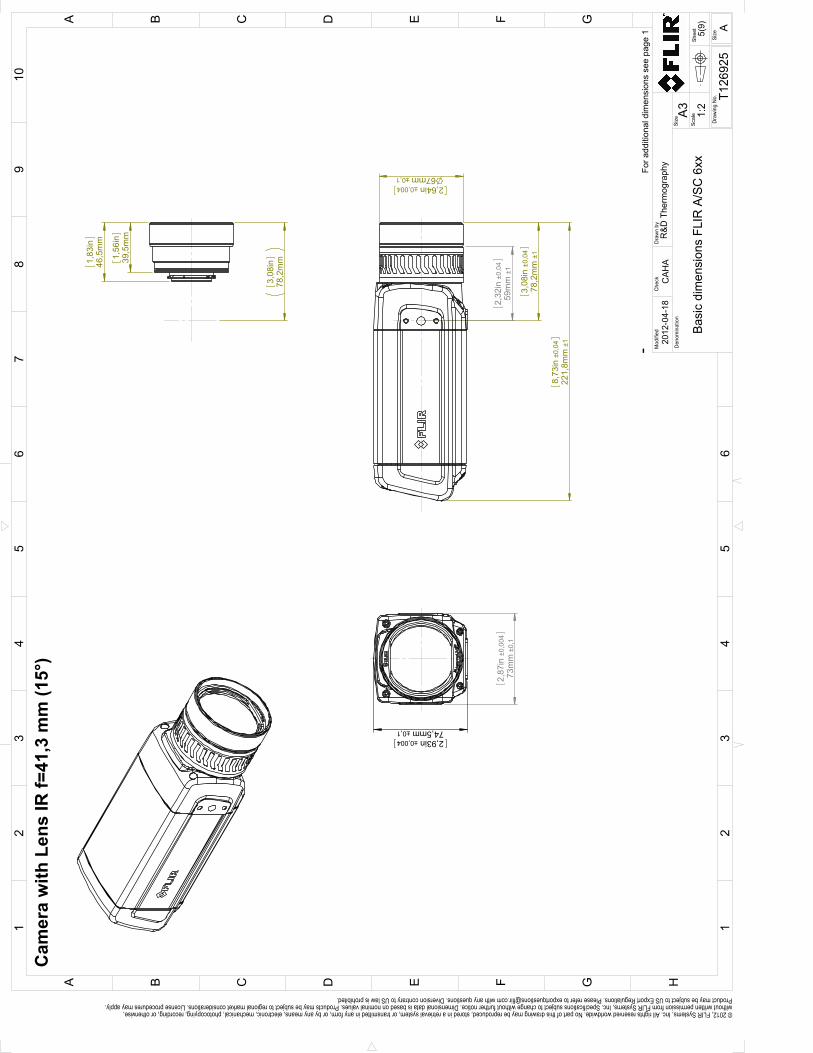
59m
m±1
2,32
in±0
,04
78,2
mm
±13,
08in
±0,0
4
67mm±0,12,64in±0,004
221,
8mm
±18,
73in
±0,0
4
73m
m±0
,12,
87in
±0,0
04
74,5mm±0,12,93in±0,004
46,5
mm
1,83
in
39,5
mm
1,56
in
78,2
mm
3,08
in
Cam
era
with
Len
s IR
f=41
,3 m
m (1
5°)
For a
dditi
onal
dim
ensi
ons
see
page
1
Shee
t
Dra
win
g N
o.
Size
Che
ckD
raw
n by
Den
omin
atio
nA3
5(9)
T126
925
Basi
c di
men
sion
s FL
IR A
/SC
6xx
CAH
A20
12-0
4-18
R&D
The
rmog
raph
yM
odifi
ed
12
34
56
78
910
A B C D E F G H
13
25
4
C FB D GEA
6Si
ze
A
1:2
Scal
e
© 2012, FLIR Systems, Inc. All rights reserved worldwide. No part of this drawing may be reproduced, stored in a retrieval system, or transmitted in any form, or by any means, electronic, mechanical, photocopying, recording, or otherwise, without written permission from FLIR Systems, Inc. Specifications subject to change without further notice. Dimensional data is based on nominal values. Products may be subject to regional market considerations. License procedures may apply. Product may be subject to US Export Regulations. Please refer to [email protected] with any questions. Diversion contrary to US law is prohibited.
-
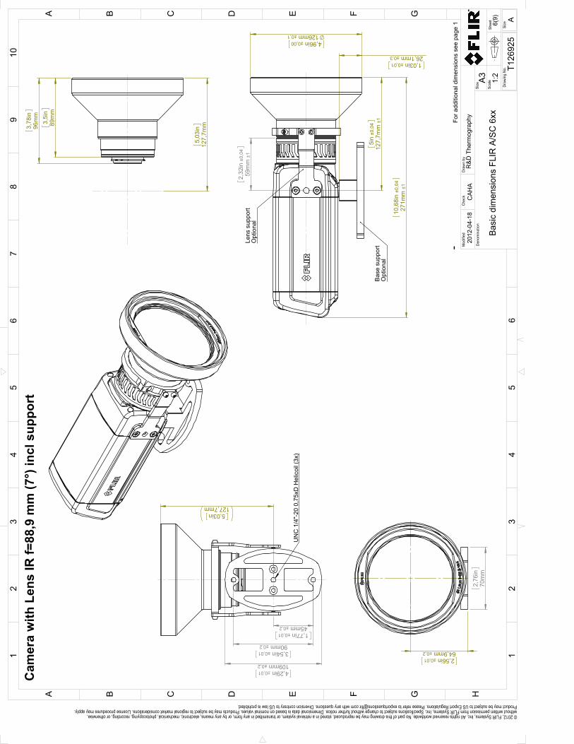
2,56in ±0,0164,9mm ±0,2
2,
76in
70m
m
2,
32in
±0,
0459
mm
±1
5i
n ±0
,04
127,
7mm
±1
10
,68i
n ±0
,04
271m
m ±
1
1,03in ±0,0126,1mm ±0,3
4,96in ±0,00126mm ±0,1
Bas
e su
ppor
tO
ptio
nal
Lens
sup
port
Opt
iona
l
3,
78in
96m
m
3,
5in
89m
m
5,
03in
127,
7mm
4,29in ±0,01109mm ±0,2
5,03in
127,7mm
3,54in ±0,0190mm ±0,2
1,77in ±0,0145mm ±0,2
UN
C 1
/4"-
20 0
,75x
D H
elic
oil (
3x)
Cam
era
with
Len
s IR
f=88
,9 m
m (7
°) in
cl s
uppo
rt
For a
dditi
onal
dim
ensi
ons
see
page
1
Shee
t
Dra
win
g N
o.
Size
Che
ckD
raw
n by
Den
omin
atio
nA3
6(9)
T126
925
Basi
c di
men
sion
s FL
IR A
/SC
6xx
CAH
A20
12-0
4-18
R&D
The
rmog
raph
yM
odifi
ed
12
34
56
78
910
A B C D E F G H
13
25
4
C FB D GEA
6Si
ze
A
1:2
Scal
e
© 2012, FLIR Systems, Inc. All rights reserved worldwide. No part of this drawing may be reproduced, stored in a retrieval system, or transmitted in any form, or by any means, electronic, mechanical, photocopying, recording, or otherwise, without written permission from FLIR Systems, Inc. Specifications subject to change without further notice. Dimensional data is based on nominal values. Products may be subject to regional market considerations. License procedures may apply. Product may be subject to US Export Regulations. Please refer to [email protected] with any questions. Diversion contrary to US law is prohibited.
-

2,
87in
±0,
0073
mm
±0,
1
2,93in ±0,0074,5mm ±0,1
2,64in ±0,0067mm ±0,1
10
,28i
n ±0
,04
261,
2mm
±1
2,
32in
±0,
0459
mm
±1
4,
63in
±0,
0411
7,6m
m ±
1
3,
11in
78,9
mm
3,
38in
85,9
mm
4,
63in
117,
6mm
Cam
era
with
Clo
se-u
p le
ns 1
,5X
(25
µm)
For a
dditi
onal
dim
ensi
ons
see
page
1
Shee
t
Dra
win
g N
o.
Size
Che
ckD
raw
n by
Den
omin
atio
nA3
7(9)
T126
925
Basi
c di
men
sion
s FL
IR A
/SC
6xx
CAH
A20
12-0
4-18
R&D
The
rmog
raph
yM
odifi
ed
12
34
56
78
910
A B C D E F G H
13
25
4
C FB D GEA
6Si
ze
A
1:2
Scal
e
© 2012, FLIR Systems, Inc. All rights reserved worldwide. No part of this drawing may be reproduced, stored in a retrieval system, or transmitted in any form, or by any means, electronic, mechanical, photocopying, recording, or otherwise, without written permission from FLIR Systems, Inc. Specifications subject to change without further notice. Dimensional data is based on nominal values. Products may be subject to regional market considerations. License procedures may apply. Product may be subject to US Export Regulations. Please refer to [email protected] with any questions. Diversion contrary to US law is prohibited.
-
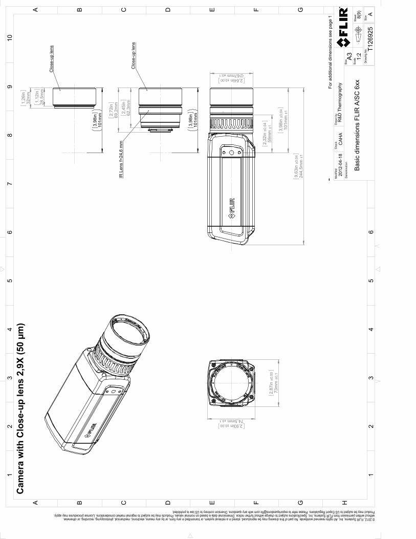
2,
87in
±0,
0073
mm
±0,
1
2,93in ±0,0074,5mm ±0,1
2,64in ±0,0067mm ±0,1
9,
63in
±0,
0424
4,5m
m ±
1
2,
32in
±0,
0459
mm
±1
3,
98in
±0,
0410
1mm
±1
2,
45in
62,3
mm
2,
72in
69,2
mm
3,
98in
101m
m
Clo
se-u
p le
ns
IR L
ens
f=24
,6 m
m
1,
26in
32m
m
1,
12in
28,5
mm
3,
98in
101m
m
Clo
se-u
p le
ns
For a
dditi
onal
dim
ensi
ons
see
page
1
Cam
era
with
Clo
se-u
p le
ns 2
,9X
(50
µm)
Shee
t
Dra
win
g N
o.
Size
Che
ckD
raw
n by
Den
omin
atio
nA3
8(9)
T126
925
Basi
c di
men
sion
s FL
IR A
/SC
6xx
CAH
A20
12-0
4-18
R&D
The
rmog
raph
yM
odifi
ed
12
34
56
78
910
A B C D E F G H
13
25
4
C FB D GEA
6Si
ze
A
1:2
Scal
e
© 2012, FLIR Systems, Inc. All rights reserved worldwide. No part of this drawing may be reproduced, stored in a retrieval system, or transmitted in any form, or by any means, electronic, mechanical, photocopying, recording, or otherwise, without written permission from FLIR Systems, Inc. Specifications subject to change without further notice. Dimensional data is based on nominal values. Products may be subject to regional market considerations. License procedures may apply. Product may be subject to US Export Regulations. Please refer to [email protected] with any questions. Diversion contrary to US law is prohibited.
-
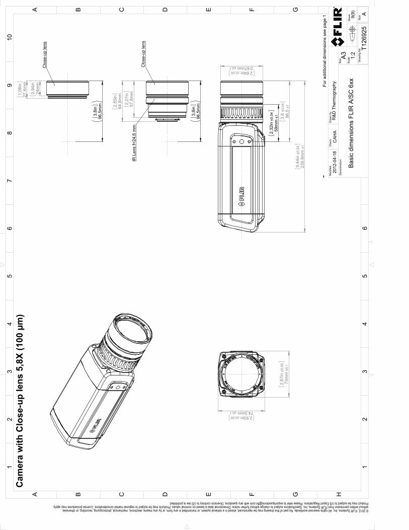
2,
87in
±0,
0073
mm
±0,
1
2,93in ±0,0074,5mm ±0,1
9,
44in
±0,
0423
9,9m
m ±
1
2,64in ±0,0067mm ±0,1
2,
32in
±0,
0459
mm
±1
3,
8 ±0
,04
96,5
±1
2,
27in
57,8
mm
2,
55in
64,8
mm
3,
8in
96,5
mm
Clo
se-u
p le
ns
IR L
ens
f=24
,6 m
m
0,
94in
24m
m
1,
08in
27,4
mm
3,
8in
96,5
mm
Clo
se-u
p le
ns
For a
dditi
onal
dim
ensi
ons
see
page
1
Cam
era
with
Clo
se-u
p le
ns 5
,8X
(100
µm
)
Shee
t
Dra
win
g N
o.
Size
Che
ckD
raw
n by
Den
omin
atio
nA3
9(9)
T126
925
Basi
c di
men
sion
s FL
IR A
/SC
6xx
CAH
A20
12-0
4-18
R&D
The
rmog
raph
yM
odifi
ed
12
34
56
78
910
A B C D E F G H
13
25
4
C FB D GEA
6Si
ze
A
1:2
Scal
e
© 2012, FLIR Systems, Inc. All rights reserved worldwide. No part of this drawing may be reproduced, stored in a retrieval system, or transmitted in any form, or by any means, electronic, mechanical, photocopying, recording, or otherwise, without written permission from FLIR Systems, Inc. Specifications subject to change without further notice. Dimensional data is based on nominal values. Products may be subject to regional market considerations. License procedures may apply. Product may be subject to US Export Regulations. Please refer to [email protected] with any questions. Diversion contrary to US law is prohibited.
-

CE Declaration of conformity17
#T559950; r. AD/35720/35720; en-US 76
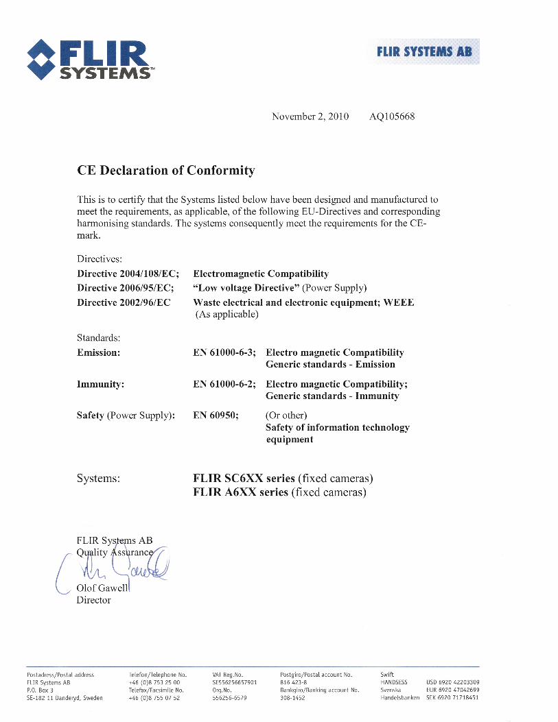
Network troubleshooting18
Try one of the following if you experience network problems:
• Reset the modem and unplug and replug the Ethernet cable at both ends.• Reboot the computer with the cables connected.• Swap your Ethernet cable with another cable that is either brand new or known to be inworking condition.
• Connect your Ethernet cable to a different wall socket. If you are still not able to get on-line, you are probably experiencing a configuration issue.
• Verify your IP address.• Disable network bridging.• Disable your Wi-Fi connectivity (if you use it) to ensure that the wired Ethernet port isopen.
• Renew the DHCP license.• Make sure that the firewall is turned off when you troubleshoot.• Make sure that your wireless adapter is switched off. If not, the search for the cameramight only look for a wireless connection.
• Normally a computer will handle both crossed and uncrossed cable types automati-cally, but for troubleshooting purposes try both or use a switch.
• Turn off any network adapters that are not connected to the camera.• For troubleshooting purposes, power both the camera and the computer using a mainsadapter. Some laptops turn off the network card to save power when using the battery.
If none of these steps help you, contact your ISP.
#T559950; r. AD/35720/35720; en-US 78

Digital I/O connection diagrams19
#T559950; r. AD/35720/35720; en-US 79
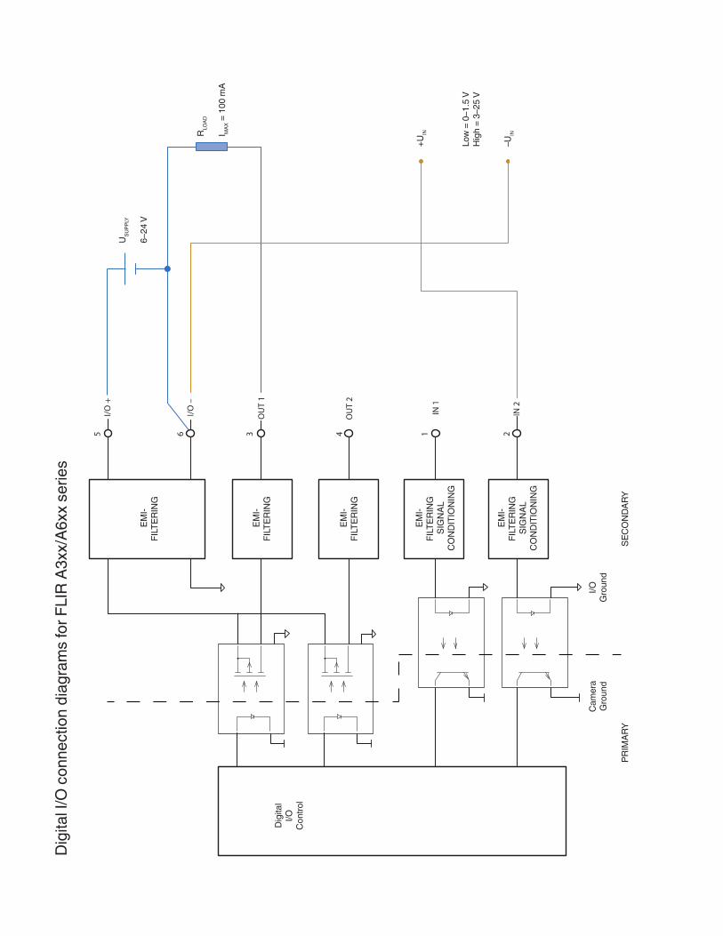
Cleaning the camera20
20.1 Camera housing, cables, and other items
20.1.1 Liquids
Use one of these liquids:
• Warm water• A weak detergent solution
20.1.2 Equipment
A soft cloth
20.1.3 Procedure
Follow this procedure:
1. Soak the cloth in the liquid.2. Twist the cloth to remove excess liquid.3. Clean the part with the cloth.
CAUTION
Do not apply solvents or similar liquids to the camera, the cables, or other items. This can cause damage.
20.2 Infrared lens
20.2.1 Liquids
Use one of these liquids:
• A commercial lens cleaning liquid with more than 30% isopropyl alcohol.• 96% ethyl alcohol (C2H5OH).
20.2.2 Equipment
Cotton wool
20.2.3 Procedure
Follow this procedure:
1. Soak the cotton wool in the liquid.2. Twist the cotton wool to remove excess liquid.3. Clean the lens one time only and discard the cotton wool.
WARNING
Make sure that you read all applicable MSDS (Material Safety Data Sheets) and warning labels on con-tainers before you use a liquid: the liquids can be dangerous.
CAUTION
• Be careful when you clean the infrared lens. The lens has a delicate anti-reflective coating.• Do not clean the infrared lens too vigorously. This can damage the anti-reflective coating.
#T559950; r. AD/35720/35720; en-US 81
Cleaning the camera20
20.3 Infrared detector
20.3.1 General
Even small amounts of dust on the infrared detector can result in major blemishes in theimage. To remove any dust from the detector, follow the procedure below.
Note
• This section only applies to cameras where removing the lens exposes the infrareddetector.
• In some cases the dust cannot be removed by following this procedure: the infrared de-tector must be cleaned mechanically. This mechanical cleaning must be carried out byan authorized service partner.
CAUTION
In Step 2 below, do not use pressurized air from pneumatic air circuits in a workshop, etc., as this air usu-ally contains oil mist to lubricate pneumatic tools.
20.3.2 Procedure
Follow this procedure:
1. Remove the lens from the camera.2. Use pressurized air from a compressed air canister to blow off the dust.
#T559950; r. AD/35720/35720; en-US 82
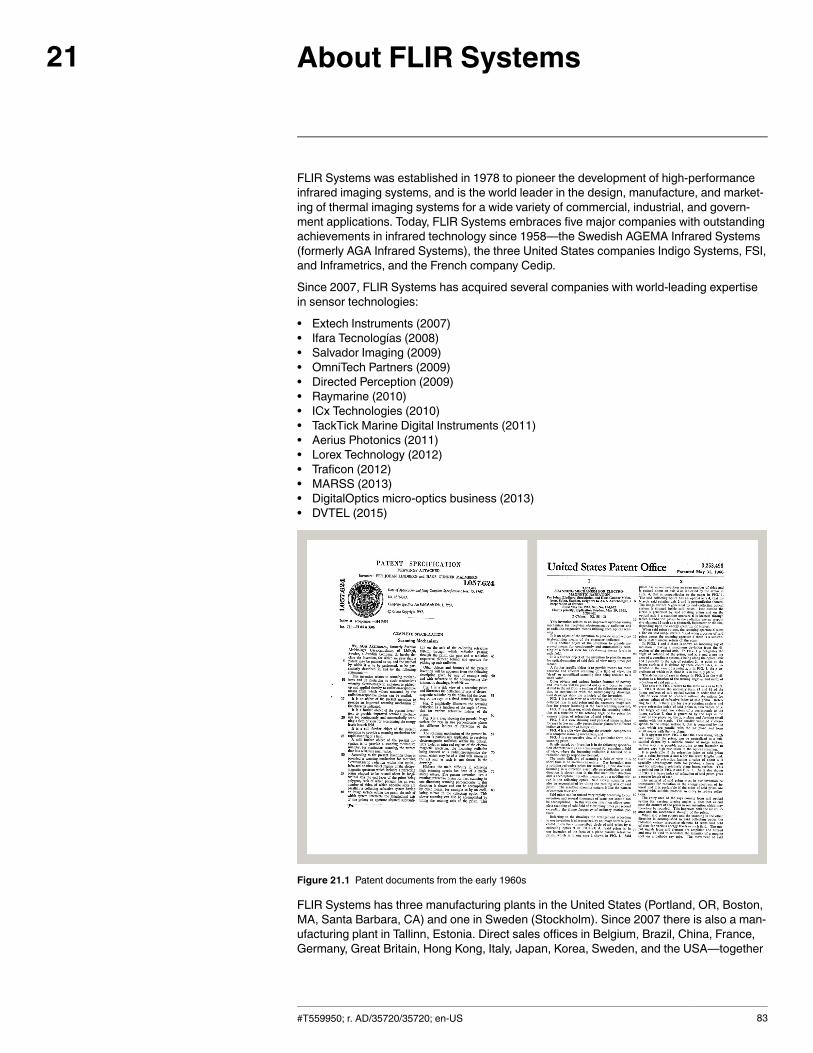
About FLIR Systems21
FLIR Systems was established in 1978 to pioneer the development of high-performanceinfrared imaging systems, and is the world leader in the design, manufacture, and market-ing of thermal imaging systems for a wide variety of commercial, industrial, and govern-ment applications. Today, FLIR Systems embraces five major companies with outstandingachievements in infrared technology since 1958—the Swedish AGEMA Infrared Systems(formerly AGA Infrared Systems), the three United States companies Indigo Systems, FSI,and Inframetrics, and the French company Cedip.
Since 2007, FLIR Systems has acquired several companies with world-leading expertisein sensor technologies:
• Extech Instruments (2007)• Ifara Tecnologías (2008)• Salvador Imaging (2009)• OmniTech Partners (2009)• Directed Perception (2009)• Raymarine (2010)• ICx Technologies (2010)• TackTick Marine Digital Instruments (2011)• Aerius Photonics (2011)• Lorex Technology (2012)• Traficon (2012)• MARSS (2013)• DigitalOptics micro-optics business (2013)• DVTEL (2015)
Figure 21.1 Patent documents from the early 1960s
FLIR Systems has three manufacturing plants in the United States (Portland, OR, Boston,MA, Santa Barbara, CA) and one in Sweden (Stockholm). Since 2007 there is also a man-ufacturing plant in Tallinn, Estonia. Direct sales offices in Belgium, Brazil, China, France,Germany, Great Britain, Hong Kong, Italy, Japan, Korea, Sweden, and the USA—together
#T559950; r. AD/35720/35720; en-US 83
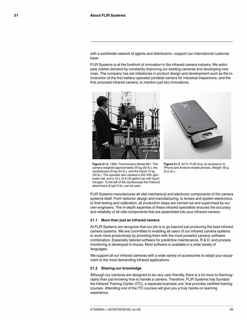
About FLIR Systems21
with a worldwide network of agents and distributors—support our international customerbase.
FLIR Systems is at the forefront of innovation in the infrared camera industry. We antici-pate market demand by constantly improving our existing cameras and developing newones. The company has set milestones in product design and development such as the in-troduction of the first battery-operated portable camera for industrial inspections, and thefirst uncooled infrared camera, to mention just two innovations.
Figure 21.2 1969: Thermovision Model 661. Thecamera weighed approximately 25 kg (55 lb.), theoscilloscope 20 kg (44 lb.), and the tripod 15 kg(33 lb.). The operator also needed a 220 VAC gen-erator set, and a 10 L (2.6 US gallon) jar with liquidnitrogen. To the left of the oscilloscope the Polaroidattachment (6 kg/13 lb.) can be seen.
Figure 21.3 2015: FLIR One, an accessory toiPhone and Android mobile phones. Weight: 90 g(3.2 oz.).
FLIR Systems manufactures all vital mechanical and electronic components of the camerasystems itself. From detector design and manufacturing, to lenses and system electronics,to final testing and calibration, all production steps are carried out and supervised by ourown engineers. The in-depth expertise of these infrared specialists ensures the accuracyand reliability of all vital components that are assembled into your infrared camera.
21.1 More than just an infrared camera
At FLIR Systems we recognize that our job is to go beyond just producing the best infraredcamera systems. We are committed to enabling all users of our infrared camera systemsto work more productively by providing them with the most powerful camera–softwarecombination. Especially tailored software for predictive maintenance, R & D, and processmonitoring is developed in-house. Most software is available in a wide variety oflanguages.
We support all our infrared cameras with a wide variety of accessories to adapt your equip-ment to the most demanding infrared applications.
21.2 Sharing our knowledge
Although our cameras are designed to be very user-friendly, there is a lot more to thermog-raphy than just knowing how to handle a camera. Therefore, FLIR Systems has foundedthe Infrared Training Center (ITC), a separate business unit, that provides certified trainingcourses. Attending one of the ITC courses will give you a truly hands-on learningexperience.
#T559950; r. AD/35720/35720; en-US 84
About FLIR Systems21
The staff of the ITC are also there to provide you with any application support you mayneed in putting infrared theory into practice.
21.3 Supporting our customers
FLIR Systems operates a worldwide service network to keep your camera running at alltimes. If you discover a problem with your camera, local service centers have all the equip-ment and expertise to solve it within the shortest possible time. Therefore, there is no needto send your camera to the other side of the world or to talk to someone who does notspeak your language.
#T559950; r. AD/35720/35720; en-US 85
Glossary22
absorption (ab-sorption factor)
The amount of radiation absorbed by an object relative to the re-ceived radiation. A number between 0 and 1.
atmosphere The gases between the object being measured and the camera, nor-mally air.
autoadjust A function making a camera perform an internal image correction.
autopalette The IR image is shown with an uneven spread of colors, displayingcold objects as well as hot ones at the same time.
blackbody Totally non-reflective object. All its radiation is due to its owntemperature.
blackbodyradiator
An IR radiating equipment with blackbody properties used to calibrateIR cameras.
calculated at-mospherictransmission
A transmission value computed from the temperature, the relative hu-midity of air and the distance to the object.
cavity radiator A bottle shaped radiator with an absorbing inside, viewed through thebottleneck.
colortemperature
The temperature for which the color of a blackbody matches a specif-ic color.
conduction The process that makes heat diffuse into a material.
continuousadjust
A function that adjusts the image. The function works all the time,continuously adjusting brightness and contrast according to the im-age content.
convection Convection is a heat transfer mode where a fluid is brought into mo-tion, either by gravity or another force, thereby transferring heat fromone place to another.
dual isotherm An isotherm with two color bands, instead of one.emissivity(emissivityfactor)
The amount of radiation coming from an object, compared to that of ablackbody. A number between 0 and 1.
emittance Amount of energy emitted from an object per unit of time and area(W/m2)
environment Objects and gases that emit radiation towards the object beingmeasured.
estimated at-mospherictransmission
A transmission value, supplied by a user, replacing a calculated one
external optics Extra lenses, filters, heat shields etc. that can be put between thecamera and the object being measured.
filter A material transparent only to some of the infrared wavelengths.
FOV Field of view: The horizontal angle that can be viewed through an IRlens.
FPA Focal plane array: A type of IR detector.
graybody An object that emits a fixed fraction of the amount of energy of ablackbody for each wavelength.
#T559950; r. AD/35720/35720; en-US 86
Glossary22
IFOV Instantaneous field of view: A measure of the geometrical resolutionof an IR camera.
image correc-tion (internal orexternal)
A way of compensating for sensitivity differences in various parts oflive images and also of stabilizing the camera.
infrared Non-visible radiation, having a wavelength from about 2–13 μm.
IR infraredisotherm A function highlighting those parts of an image that fall above, below
or between one or more temperature intervals.
isothermalcavity
A bottle-shaped radiator with a uniform temperature viewed throughthe bottleneck.
Laser LocatIR An electrically powered light source on the camera that emits laser ra-diation in a thin, concentrated beam to point at certain parts of the ob-ject in front of the camera.
laser pointer An electrically powered light source on the camera that emits laser ra-diation in a thin, concentrated beam to point at certain parts of the ob-ject in front of the camera.
level The center value of the temperature scale, usually expressed as asignal value.
manual adjust A way to adjust the image by manually changing certain parameters.
NETD Noise equivalent temperature difference. A measure of the imagenoise level of an IR camera.
noise Undesired small disturbance in the infrared image
objectparameters
A set of values describing the circumstances under which the meas-urement of an object was made, and the object itself (such as emis-sivity, reflected apparent temperature, distance etc.)
object signal A non-calibrated value related to the amount of radiation received bythe camera from the object.
palette The set of colors used to display an IR image.
pixel Stands for picture element. One single spot in an image.
radiance Amount of energy emitted from an object per unit of time, area andangle (W/m2/sr)
radiant power Amount of energy emitted from an object per unit of time (W)
radiation The process by which electromagnetic energy, is emitted by an objector a gas.
radiator A piece of IR radiating equipment.range The current overall temperature measurement limitation of an IR cam-
era. Cameras can have several ranges. Expressed as two blackbodytemperatures that limit the current calibration.
referencetemperature
A temperature which the ordinary measured values can be comparedwith.
reflection The amount of radiation reflected by an object relative to the receivedradiation. A number between 0 and 1.
#T559950; r. AD/35720/35720; en-US 87
Glossary22
relativehumidity
Relative humidity represents the ratio between the current water va-pour mass in the air and the maximum it may contain in saturationconditions.
saturationcolor
The areas that contain temperatures outside the present level/spansettings are colored with the saturation colors. The saturation colorscontain an ‘overflow’ color and an ‘underflow’ color. There is also athird red saturation color that marks everything saturated by the de-tector indicating that the range should probably be changed.
span The interval of the temperature scale, usually expressed as a signalvalue.
spectral (radi-ant) emittance
Amount of energy emitted from an object per unit of time, area andwavelength (W/m2/μm)
temperaturedifference, ordifference oftemperature.
A value which is the result of a subtraction between two temperaturevalues.
temperaturerange
The current overall temperature measurement limitation of an IR cam-era. Cameras can have several ranges. Expressed as two blackbodytemperatures that limit the current calibration.
temperaturescale
The way in which an IR image currently is displayed. Expressed astwo temperature values limiting the colors.
thermogram infrared image
transmission(or transmit-tance) factor
Gases and materials can be more or less transparent. Transmissionis the amount of IR radiation passing through them. A number be-tween 0 and 1.
transparentisotherm
An isotherm showing a linear spread of colors, instead of covering thehighlighted parts of the image.
visual Refers to the video mode of a IR camera, as opposed to the normal,thermographic mode. When a camera is in video mode it captures or-dinary video images, while thermographic images are captured whenthe camera is in IR mode.
#T559950; r. AD/35720/35720; en-US 88
Thermographic measurementtechniques
23
23.1 Introduction
An infrared camera measures and images the emitted infrared radiation from an object.The fact that radiation is a function of object surface temperature makes it possible for thecamera to calculate and display this temperature.
However, the radiation measured by the camera does not only depend on the temperatureof the object but is also a function of the emissivity. Radiation also originates from the sur-roundings and is reflected in the object. The radiation from the object and the reflected ra-diation will also be influenced by the absorption of the atmosphere.
To measure temperature accurately, it is therefore necessary to compensate for the effectsof a number of different radiation sources. This is done on-line automatically by the cam-era. The following object parameters must, however, be supplied for the camera:
• The emissivity of the object• The reflected apparent temperature• The distance between the object and the camera• The relative humidity• Temperature of the atmosphere
23.2 Emissivity
The most important object parameter to set correctly is the emissivity which, in short, is ameasure of how much radiation is emitted from the object, compared to that from a perfectblackbody of the same temperature.
Normally, object materials and surface treatments exhibit emissivity ranging from approxi-mately 0.1 to 0.95. A highly polished (mirror) surface falls below 0.1, while an oxidized orpainted surface has a higher emissivity. Oil-based paint, regardless of color in the visiblespectrum, has an emissivity over 0.9 in the infrared. Human skin exhibits an emissivity0.97 to 0.98.
Non-oxidized metals represent an extreme case of perfect opacity and high reflexivity,which does not vary greatly with wavelength. Consequently, the emissivity of metals is low– only increasing with temperature. For non-metals, emissivity tends to be high, and de-creases with temperature.
23.2.1 Finding the emissivity of a sample
23.2.1.1 Step 1: Determining reflected apparent temperature
Use one of the following two methods to determine reflected apparent temperature:
#T559950; r. AD/35720/35720; en-US 89
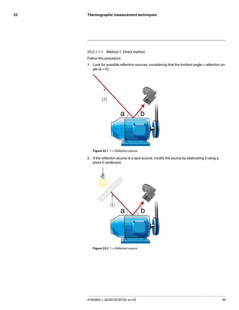
Thermographic measurement techniques23
23.2.1.1.1 Method 1: Direct method
Follow this procedure:
1. Look for possible reflection sources, considering that the incident angle = reflection an-gle (a = b).
Figure 23.1 1 = Reflection source
2. If the reflection source is a spot source, modify the source by obstructing it using apiece if cardboard.
Figure 23.2 1 = Reflection source
#T559950; r. AD/35720/35720; en-US 90

Thermographic measurement techniques23
3. Measure the radiation intensity (= apparent temperature) from the reflecting source us-ing the following settings:
• Emissivity: 1.0• Dobj: 0
You can measure the radiation intensity using one of the following two methods:
Figure 23.3 1 = Reflection source Figure 23.4 1 = Reflection source
Using a thermocouple to measure reflected apparent temperature is not recommended fortwo important reasons:
• A thermocouple does not measure radiation intensity• A thermocouple requires a very good thermal contact to the surface, usually by gluingand covering the sensor by a thermal isolator.
23.2.1.1.2 Method 2: Reflector method
Follow this procedure:
1. Crumble up a large piece of aluminum foil.2. Uncrumble the aluminum foil and attach it to a piece of cardboard of the same size.3. Put the piece of cardboard in front of the object you want to measure. Make sure that
the side with aluminum foil points to the camera.4. Set the emissivity to 1.0.
#T559950; r. AD/35720/35720; en-US 91
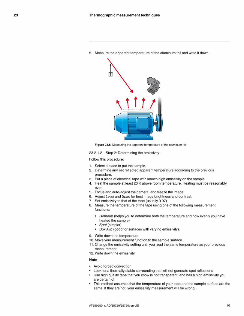
Thermographic measurement techniques23
5. Measure the apparent temperature of the aluminum foil and write it down.
Figure 23.5 Measuring the apparent temperature of the aluminum foil.
23.2.1.2 Step 2: Determining the emissivity
Follow this procedure:
1. Select a place to put the sample.2. Determine and set reflected apparent temperature according to the previous
procedure.3. Put a piece of electrical tape with known high emissivity on the sample.4. Heat the sample at least 20 K above room temperature. Heating must be reasonably
even.5. Focus and auto-adjust the camera, and freeze the image.6. Adjust Level and Span for best image brightness and contrast.7. Set emissivity to that of the tape (usually 0.97).8. Measure the temperature of the tape using one of the following measurement
functions:
• Isotherm (helps you to determine both the temperature and how evenly you haveheated the sample)
• Spot (simpler)• Box Avg (good for surfaces with varying emissivity).
9. Write down the temperature.10. Move your measurement function to the sample surface.11. Change the emissivity setting until you read the same temperature as your previous
measurement.12.Write down the emissivity.
Note
• Avoid forced convection• Look for a thermally stable surrounding that will not generate spot reflections• Use high quality tape that you know is not transparent, and has a high emissivity youare certain of
• This method assumes that the temperature of your tape and the sample surface are thesame. If they are not, your emissivity measurement will be wrong.
#T559950; r. AD/35720/35720; en-US 92
Thermographic measurement techniques23
23.3 Reflected apparent temperature
This parameter is used to compensate for the radiation reflected in the object. If the emis-sivity is low and the object temperature relatively far from that of the reflected it will be im-portant to set and compensate for the reflected apparent temperature correctly.
23.4 Distance
The distance is the distance between the object and the front lens of the camera. This pa-rameter is used to compensate for the following two facts:
• That radiation from the target is absorbed by the atmosphere between the object andthe camera.
• That radiation from the atmosphere itself is detected by the camera.
23.5 Relative humidity
The camera can also compensate for the fact that the transmittance is also dependent onthe relative humidity of the atmosphere. To do this set the relative humidity to the correctvalue. For short distances and normal humidity the relative humidity can normally be left ata default value of 50%.
23.6 Other parameters
In addition, some cameras and analysis programs from FLIR Systems allow you to com-pensate for the following parameters:
• Atmospheric temperature – i.e. the temperature of the atmosphere between the cameraand the target
• External optics temperature – i.e. the temperature of any external lenses or windowsused in front of the camera
• External optics transmittance – i.e. the transmission of any external lenses or windowsused in front of the camera
#T559950; r. AD/35720/35720; en-US 93
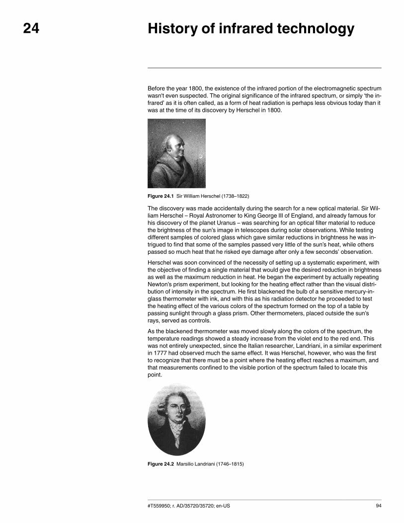
History of infrared technology24
Before the year 1800, the existence of the infrared portion of the electromagnetic spectrumwasn't even suspected. The original significance of the infrared spectrum, or simply ‘the in-frared’ as it is often called, as a form of heat radiation is perhaps less obvious today than itwas at the time of its discovery by Herschel in 1800.
Figure 24.1 Sir William Herschel (1738–1822)
The discovery was made accidentally during the search for a new optical material. Sir Wil-liam Herschel – Royal Astronomer to King George III of England, and already famous forhis discovery of the planet Uranus – was searching for an optical filter material to reducethe brightness of the sun’s image in telescopes during solar observations. While testingdifferent samples of colored glass which gave similar reductions in brightness he was in-trigued to find that some of the samples passed very little of the sun’s heat, while otherspassed so much heat that he risked eye damage after only a few seconds’ observation.
Herschel was soon convinced of the necessity of setting up a systematic experiment, withthe objective of finding a single material that would give the desired reduction in brightnessas well as the maximum reduction in heat. He began the experiment by actually repeatingNewton’s prism experiment, but looking for the heating effect rather than the visual distri-bution of intensity in the spectrum. He first blackened the bulb of a sensitive mercury-in-glass thermometer with ink, and with this as his radiation detector he proceeded to testthe heating effect of the various colors of the spectrum formed on the top of a table bypassing sunlight through a glass prism. Other thermometers, placed outside the sun’srays, served as controls.
As the blackened thermometer was moved slowly along the colors of the spectrum, thetemperature readings showed a steady increase from the violet end to the red end. Thiswas not entirely unexpected, since the Italian researcher, Landriani, in a similar experimentin 1777 had observed much the same effect. It was Herschel, however, who was the firstto recognize that there must be a point where the heating effect reaches a maximum, andthat measurements confined to the visible portion of the spectrum failed to locate thispoint.
Figure 24.2 Marsilio Landriani (1746–1815)
#T559950; r. AD/35720/35720; en-US 94
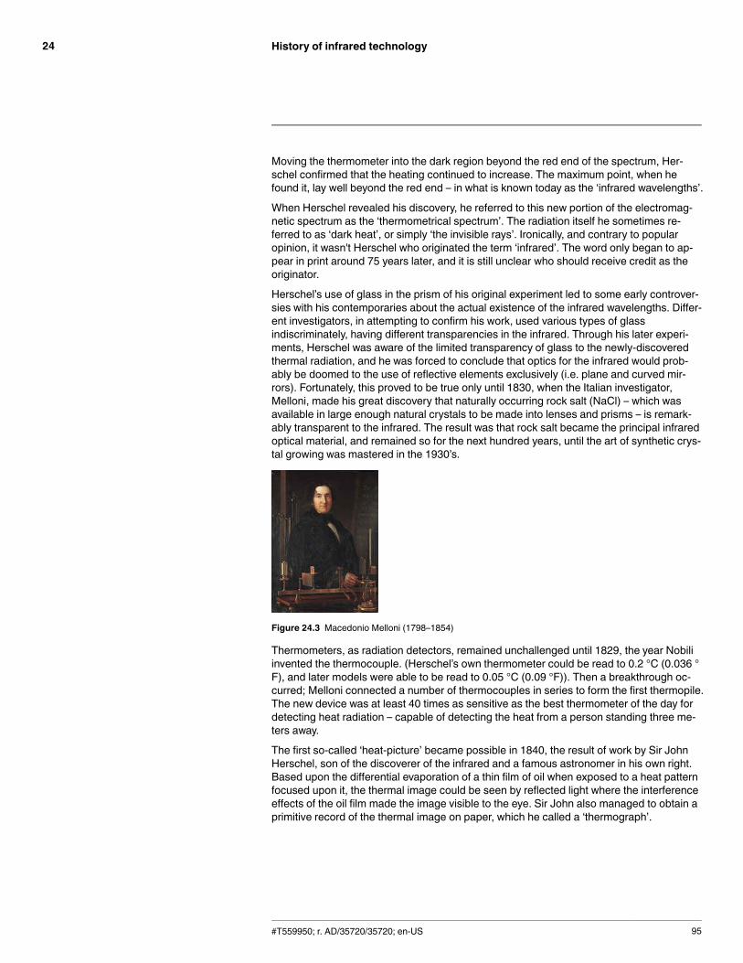
History of infrared technology24
Moving the thermometer into the dark region beyond the red end of the spectrum, Her-schel confirmed that the heating continued to increase. The maximum point, when hefound it, lay well beyond the red end – in what is known today as the ‘infrared wavelengths’.
When Herschel revealed his discovery, he referred to this new portion of the electromag-netic spectrum as the ‘thermometrical spectrum’. The radiation itself he sometimes re-ferred to as ‘dark heat’, or simply ‘the invisible rays’. Ironically, and contrary to popularopinion, it wasn't Herschel who originated the term ‘infrared’. The word only began to ap-pear in print around 75 years later, and it is still unclear who should receive credit as theoriginator.
Herschel’s use of glass in the prism of his original experiment led to some early controver-sies with his contemporaries about the actual existence of the infrared wavelengths. Differ-ent investigators, in attempting to confirm his work, used various types of glassindiscriminately, having different transparencies in the infrared. Through his later experi-ments, Herschel was aware of the limited transparency of glass to the newly-discoveredthermal radiation, and he was forced to conclude that optics for the infrared would prob-ably be doomed to the use of reflective elements exclusively (i.e. plane and curved mir-rors). Fortunately, this proved to be true only until 1830, when the Italian investigator,Melloni, made his great discovery that naturally occurring rock salt (NaCl) – which wasavailable in large enough natural crystals to be made into lenses and prisms – is remark-ably transparent to the infrared. The result was that rock salt became the principal infraredoptical material, and remained so for the next hundred years, until the art of synthetic crys-tal growing was mastered in the 1930’s.
Figure 24.3 Macedonio Melloni (1798–1854)
Thermometers, as radiation detectors, remained unchallenged until 1829, the year Nobiliinvented the thermocouple. (Herschel’s own thermometer could be read to 0.2 °C (0.036 °F), and later models were able to be read to 0.05 °C (0.09 °F)). Then a breakthrough oc-curred; Melloni connected a number of thermocouples in series to form the first thermopile.The new device was at least 40 times as sensitive as the best thermometer of the day fordetecting heat radiation – capable of detecting the heat from a person standing three me-ters away.
The first so-called ‘heat-picture’ became possible in 1840, the result of work by Sir JohnHerschel, son of the discoverer of the infrared and a famous astronomer in his own right.Based upon the differential evaporation of a thin film of oil when exposed to a heat patternfocused upon it, the thermal image could be seen by reflected light where the interferenceeffects of the oil film made the image visible to the eye. Sir John also managed to obtain aprimitive record of the thermal image on paper, which he called a ‘thermograph’.
#T559950; r. AD/35720/35720; en-US 95
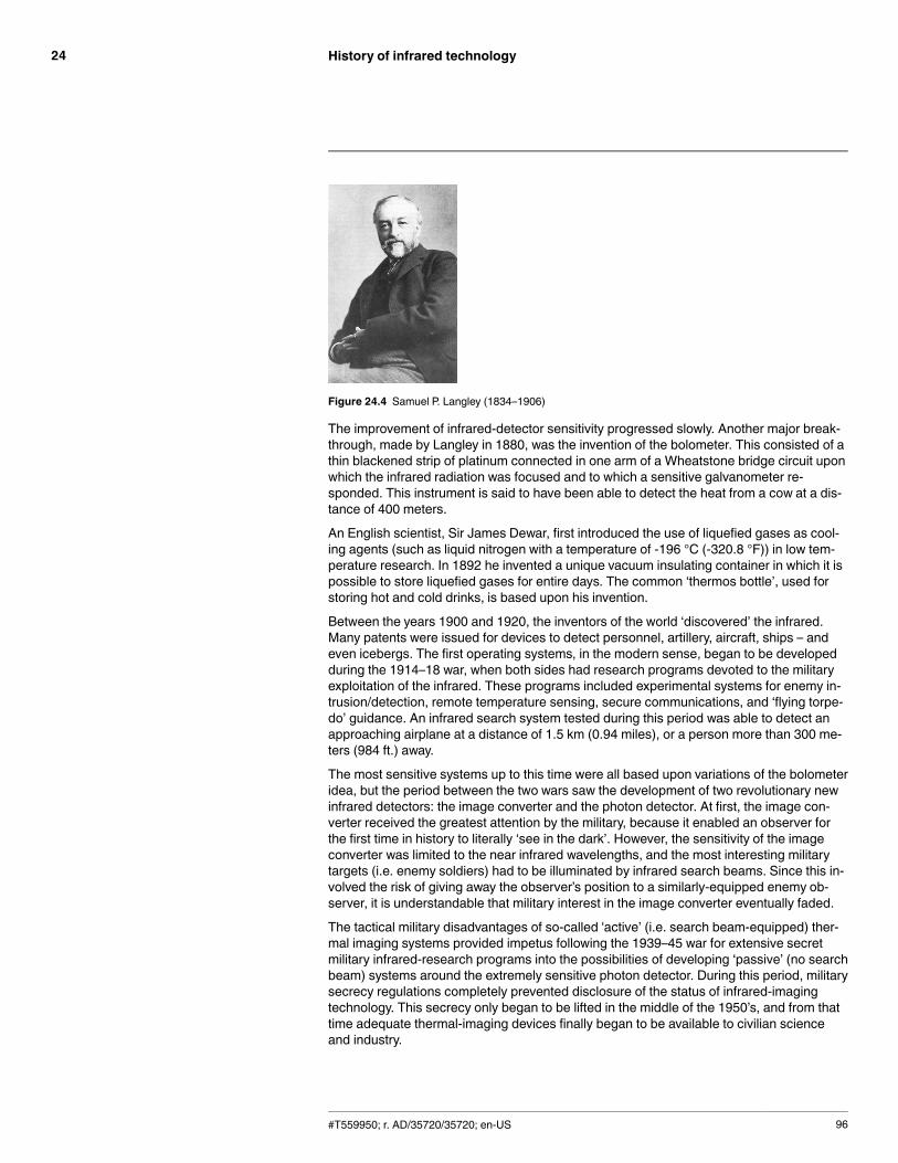
History of infrared technology24
Figure 24.4 Samuel P. Langley (1834–1906)
The improvement of infrared-detector sensitivity progressed slowly. Another major break-through, made by Langley in 1880, was the invention of the bolometer. This consisted of athin blackened strip of platinum connected in one arm of a Wheatstone bridge circuit uponwhich the infrared radiation was focused and to which a sensitive galvanometer re-sponded. This instrument is said to have been able to detect the heat from a cow at a dis-tance of 400 meters.
An English scientist, Sir James Dewar, first introduced the use of liquefied gases as cool-ing agents (such as liquid nitrogen with a temperature of -196 °C (-320.8 °F)) in low tem-perature research. In 1892 he invented a unique vacuum insulating container in which it ispossible to store liquefied gases for entire days. The common ‘thermos bottle’, used forstoring hot and cold drinks, is based upon his invention.
Between the years 1900 and 1920, the inventors of the world ‘discovered’ the infrared.Many patents were issued for devices to detect personnel, artillery, aircraft, ships – andeven icebergs. The first operating systems, in the modern sense, began to be developedduring the 1914–18 war, when both sides had research programs devoted to the militaryexploitation of the infrared. These programs included experimental systems for enemy in-trusion/detection, remote temperature sensing, secure communications, and ‘flying torpe-do’ guidance. An infrared search system tested during this period was able to detect anapproaching airplane at a distance of 1.5 km (0.94 miles), or a person more than 300 me-ters (984 ft.) away.
The most sensitive systems up to this time were all based upon variations of the bolometeridea, but the period between the two wars saw the development of two revolutionary newinfrared detectors: the image converter and the photon detector. At first, the image con-verter received the greatest attention by the military, because it enabled an observer forthe first time in history to literally ‘see in the dark’. However, the sensitivity of the imageconverter was limited to the near infrared wavelengths, and the most interesting militarytargets (i.e. enemy soldiers) had to be illuminated by infrared search beams. Since this in-volved the risk of giving away the observer’s position to a similarly-equipped enemy ob-server, it is understandable that military interest in the image converter eventually faded.
The tactical military disadvantages of so-called 'active’ (i.e. search beam-equipped) ther-mal imaging systems provided impetus following the 1939–45 war for extensive secretmilitary infrared-research programs into the possibilities of developing ‘passive’ (no searchbeam) systems around the extremely sensitive photon detector. During this period, militarysecrecy regulations completely prevented disclosure of the status of infrared-imagingtechnology. This secrecy only began to be lifted in the middle of the 1950’s, and from thattime adequate thermal-imaging devices finally began to be available to civilian scienceand industry.
#T559950; r. AD/35720/35720; en-US 96
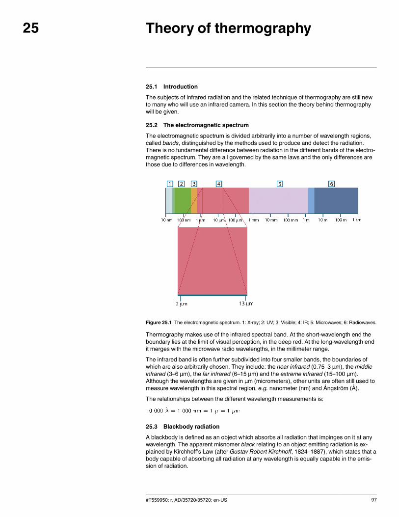
Theory of thermography25
25.1 Introduction
The subjects of infrared radiation and the related technique of thermography are still newto many who will use an infrared camera. In this section the theory behind thermographywill be given.
25.2 The electromagnetic spectrum
The electromagnetic spectrum is divided arbitrarily into a number of wavelength regions,called bands, distinguished by the methods used to produce and detect the radiation.There is no fundamental difference between radiation in the different bands of the electro-magnetic spectrum. They are all governed by the same laws and the only differences arethose due to differences in wavelength.
Figure 25.1 The electromagnetic spectrum. 1: X-ray; 2: UV; 3: Visible; 4: IR; 5: Microwaves; 6: Radiowaves.
Thermography makes use of the infrared spectral band. At the short-wavelength end theboundary lies at the limit of visual perception, in the deep red. At the long-wavelength endit merges with the microwave radio wavelengths, in the millimeter range.
The infrared band is often further subdivided into four smaller bands, the boundaries ofwhich are also arbitrarily chosen. They include: the near infrared (0.75–3 μm), themiddleinfrared (3–6 μm), the far infrared (6–15 μm) and the extreme infrared (15–100 μm).Although the wavelengths are given in μm (micrometers), other units are often still used tomeasure wavelength in this spectral region, e.g. nanometer (nm) and Ångström (Å).
The relationships between the different wavelength measurements is:
25.3 Blackbody radiation
A blackbody is defined as an object which absorbs all radiation that impinges on it at anywavelength. The apparent misnomer black relating to an object emitting radiation is ex-plained by Kirchhoff’s Law (after Gustav Robert Kirchhoff, 1824–1887), which states that abody capable of absorbing all radiation at any wavelength is equally capable in the emis-sion of radiation.
#T559950; r. AD/35720/35720; en-US 97
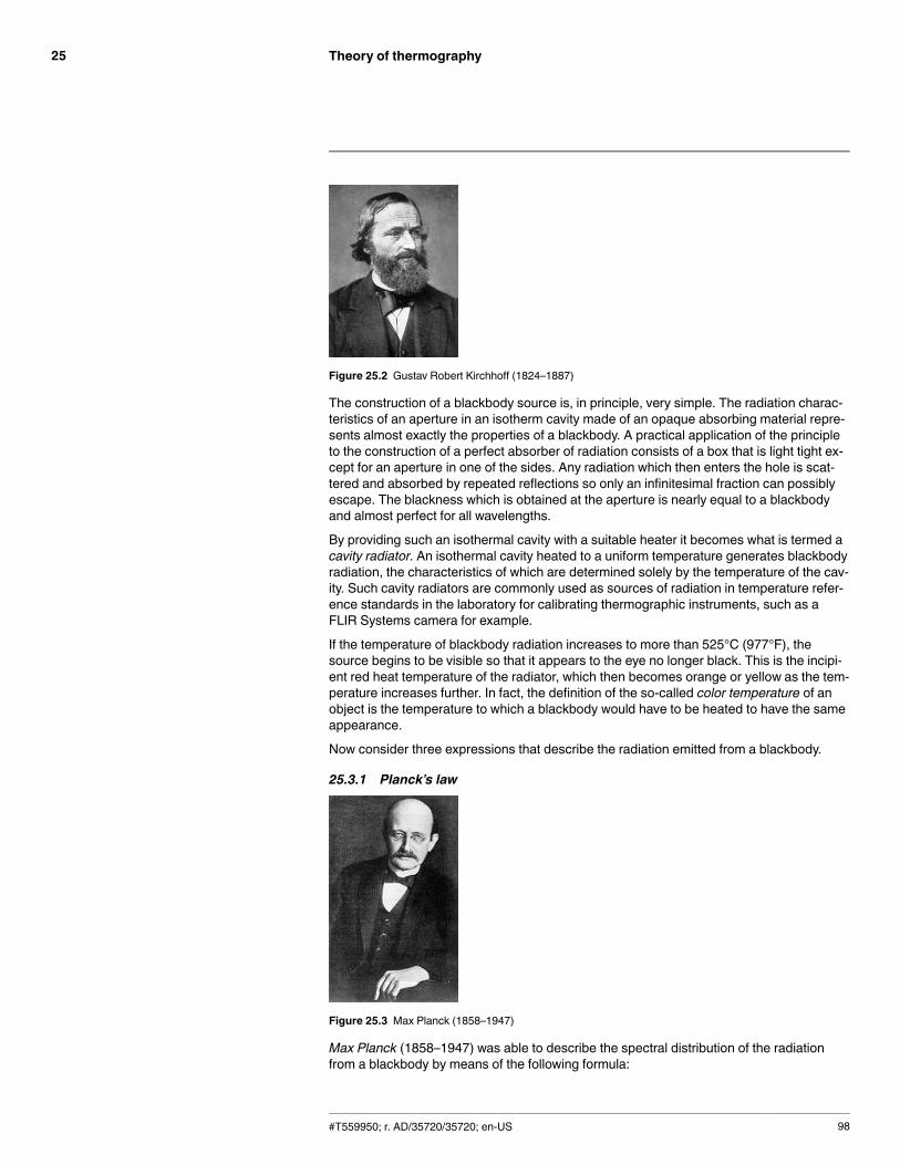
Theory of thermography25
Figure 25.2 Gustav Robert Kirchhoff (1824–1887)
The construction of a blackbody source is, in principle, very simple. The radiation charac-teristics of an aperture in an isotherm cavity made of an opaque absorbing material repre-sents almost exactly the properties of a blackbody. A practical application of the principleto the construction of a perfect absorber of radiation consists of a box that is light tight ex-cept for an aperture in one of the sides. Any radiation which then enters the hole is scat-tered and absorbed by repeated reflections so only an infinitesimal fraction can possiblyescape. The blackness which is obtained at the aperture is nearly equal to a blackbodyand almost perfect for all wavelengths.
By providing such an isothermal cavity with a suitable heater it becomes what is termed acavity radiator. An isothermal cavity heated to a uniform temperature generates blackbodyradiation, the characteristics of which are determined solely by the temperature of the cav-ity. Such cavity radiators are commonly used as sources of radiation in temperature refer-ence standards in the laboratory for calibrating thermographic instruments, such as aFLIR Systems camera for example.
If the temperature of blackbody radiation increases to more than 525°C (977°F), thesource begins to be visible so that it appears to the eye no longer black. This is the incipi-ent red heat temperature of the radiator, which then becomes orange or yellow as the tem-perature increases further. In fact, the definition of the so-called color temperature of anobject is the temperature to which a blackbody would have to be heated to have the sameappearance.
Now consider three expressions that describe the radiation emitted from a blackbody.
25.3.1 Planck’s law
Figure 25.3 Max Planck (1858–1947)
Max Planck (1858–1947) was able to describe the spectral distribution of the radiationfrom a blackbody by means of the following formula:
#T559950; r. AD/35720/35720; en-US 98
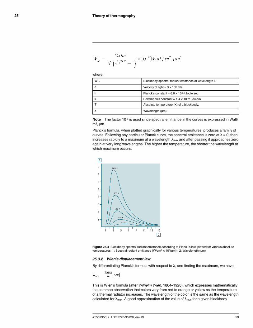
Theory of thermography25
where:Wλb Blackbody spectral radiant emittance at wavelength λ.
c Velocity of light = 3 × 10⁸ m/s
h Planck’s constant = 6.6 × 10⁻³⁴ Joule sec.
k Boltzmann’s constant = 1.4 × 10⁻²³ Joule/K.
T Absolute temperature (K) of a blackbody.
λ Wavelength (μm).
Note The factor 10-6 is used since spectral emittance in the curves is expressed in Watt/m2, μm.Planck’s formula, when plotted graphically for various temperatures, produces a family ofcurves. Following any particular Planck curve, the spectral emittance is zero at λ = 0, thenincreases rapidly to a maximum at a wavelength λmax and after passing it approaches zeroagain at very long wavelengths. The higher the temperature, the shorter the wavelength atwhich maximum occurs.
Figure 25.4 Blackbody spectral radiant emittance according to Planck’s law, plotted for various absolutetemperatures. 1: Spectral radiant emittance (W/cm2 × 103(μm)); 2: Wavelength (μm)
25.3.2 Wien’s displacement law
By differentiating Planck’s formula with respect to λ, and finding the maximum, we have:
This is Wien’s formula (afterWilhelm Wien, 1864–1928), which expresses mathematicallythe common observation that colors vary from red to orange or yellow as the temperatureof a thermal radiator increases. The wavelength of the color is the same as the wavelengthcalculated for λmax. A good approximation of the value of λmax for a given blackbody
#T559950; r. AD/35720/35720; en-US 99
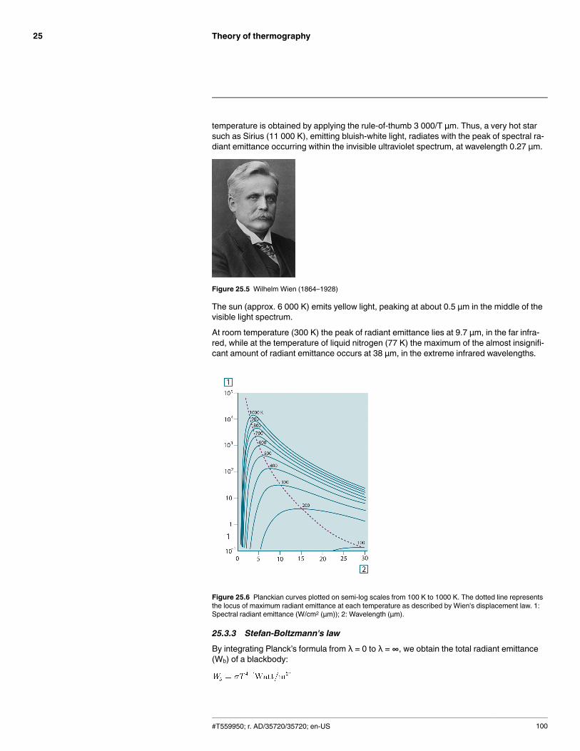
Theory of thermography25
temperature is obtained by applying the rule-of-thumb 3 000/T μm. Thus, a very hot starsuch as Sirius (11 000 K), emitting bluish-white light, radiates with the peak of spectral ra-diant emittance occurring within the invisible ultraviolet spectrum, at wavelength 0.27 μm.
Figure 25.5 Wilhelm Wien (1864–1928)
The sun (approx. 6 000 K) emits yellow light, peaking at about 0.5 μm in the middle of thevisible light spectrum.
At room temperature (300 K) the peak of radiant emittance lies at 9.7 μm, in the far infra-red, while at the temperature of liquid nitrogen (77 K) the maximum of the almost insignifi-cant amount of radiant emittance occurs at 38 μm, in the extreme infrared wavelengths.
Figure 25.6 Planckian curves plotted on semi-log scales from 100 K to 1000 K. The dotted line representsthe locus of maximum radiant emittance at each temperature as described by Wien's displacement law. 1:Spectral radiant emittance (W/cm2 (μm)); 2: Wavelength (μm).
25.3.3 Stefan-Boltzmann's law
By integrating Planck’s formula from λ = 0 to λ = ∞, we obtain the total radiant emittance(Wb) of a blackbody:
#T559950; r. AD/35720/35720; en-US 100
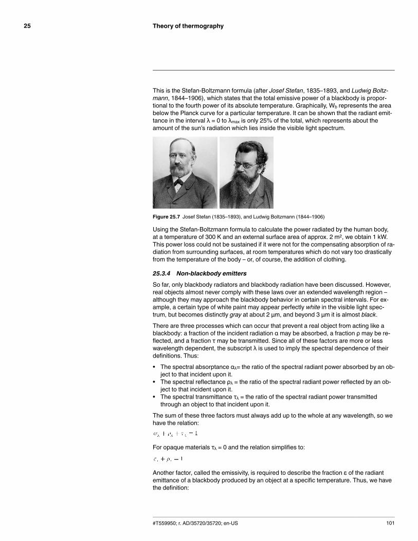
Theory of thermography25
This is the Stefan-Boltzmann formula (after Josef Stefan, 1835–1893, and Ludwig Boltz-mann, 1844–1906), which states that the total emissive power of a blackbody is propor-tional to the fourth power of its absolute temperature. Graphically, Wb represents the areabelow the Planck curve for a particular temperature. It can be shown that the radiant emit-tance in the interval λ = 0 to λmax is only 25% of the total, which represents about theamount of the sun’s radiation which lies inside the visible light spectrum.
Figure 25.7 Josef Stefan (1835–1893), and Ludwig Boltzmann (1844–1906)
Using the Stefan-Boltzmann formula to calculate the power radiated by the human body,at a temperature of 300 K and an external surface area of approx. 2 m2, we obtain 1 kW.This power loss could not be sustained if it were not for the compensating absorption of ra-diation from surrounding surfaces, at room temperatures which do not vary too drasticallyfrom the temperature of the body – or, of course, the addition of clothing.
25.3.4 Non-blackbody emitters
So far, only blackbody radiators and blackbody radiation have been discussed. However,real objects almost never comply with these laws over an extended wavelength region –although they may approach the blackbody behavior in certain spectral intervals. For ex-ample, a certain type of white paint may appear perfectly white in the visible light spec-trum, but becomes distinctly gray at about 2 μm, and beyond 3 μm it is almost black.
There are three processes which can occur that prevent a real object from acting like ablackbody: a fraction of the incident radiation α may be absorbed, a fraction ρ may be re-flected, and a fraction τ may be transmitted. Since all of these factors are more or lesswavelength dependent, the subscript λ is used to imply the spectral dependence of theirdefinitions. Thus:
• The spectral absorptance αλ= the ratio of the spectral radiant power absorbed by an ob-ject to that incident upon it.
• The spectral reflectance ρλ = the ratio of the spectral radiant power reflected by an ob-ject to that incident upon it.
• The spectral transmittance τλ = the ratio of the spectral radiant power transmittedthrough an object to that incident upon it.
The sum of these three factors must always add up to the whole at any wavelength, so wehave the relation:
For opaque materials τλ = 0 and the relation simplifies to:
Another factor, called the emissivity, is required to describe the fraction ε of the radiantemittance of a blackbody produced by an object at a specific temperature. Thus, we havethe definition:
#T559950; r. AD/35720/35720; en-US 101
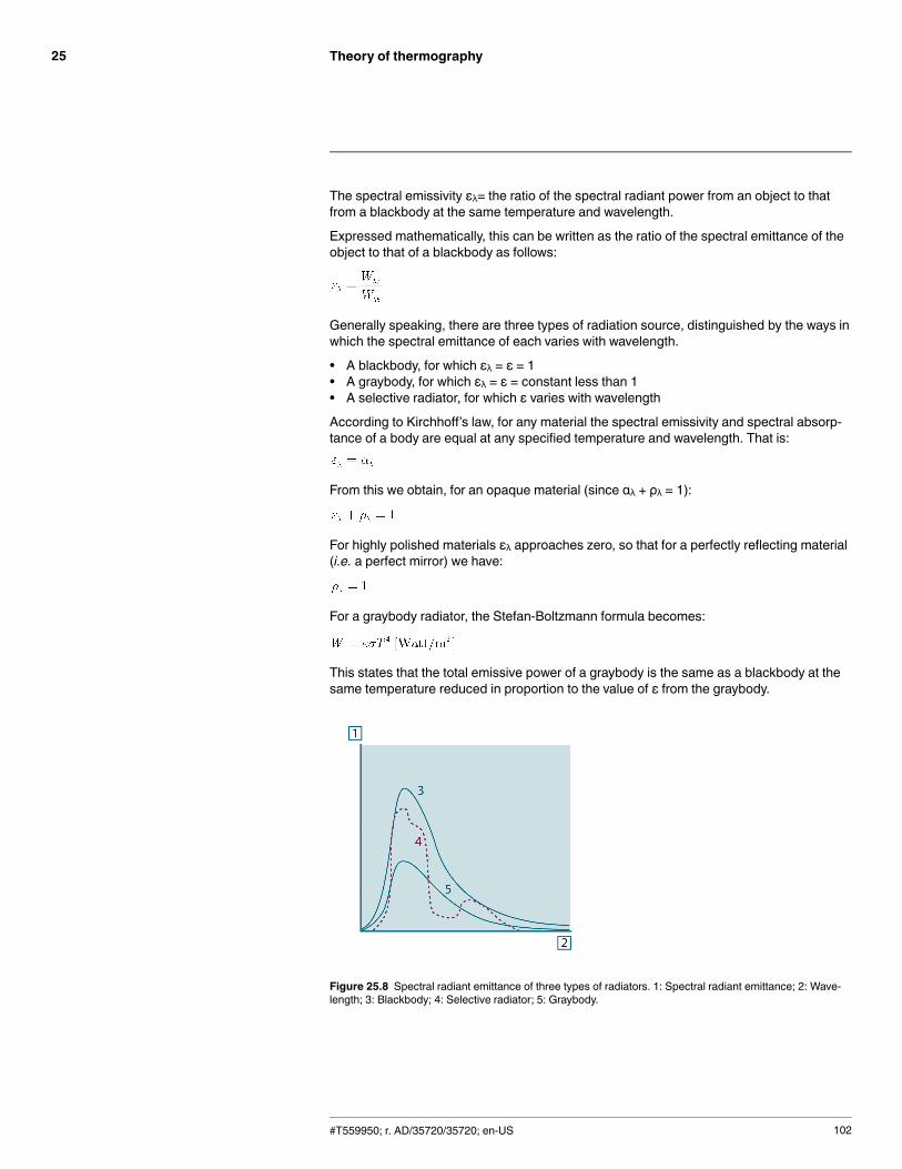
Theory of thermography25
The spectral emissivity ελ= the ratio of the spectral radiant power from an object to thatfrom a blackbody at the same temperature and wavelength.
Expressed mathematically, this can be written as the ratio of the spectral emittance of theobject to that of a blackbody as follows:
Generally speaking, there are three types of radiation source, distinguished by the ways inwhich the spectral emittance of each varies with wavelength.
• A blackbody, for which ελ = ε = 1• A graybody, for which ελ = ε = constant less than 1• A selective radiator, for which ε varies with wavelength
According to Kirchhoff’s law, for any material the spectral emissivity and spectral absorp-tance of a body are equal at any specified temperature and wavelength. That is:
From this we obtain, for an opaque material (since αλ + ρλ = 1):
For highly polished materials ελ approaches zero, so that for a perfectly reflecting material(i.e. a perfect mirror) we have:
For a graybody radiator, the Stefan-Boltzmann formula becomes:
This states that the total emissive power of a graybody is the same as a blackbody at thesame temperature reduced in proportion to the value of ε from the graybody.
Figure 25.8 Spectral radiant emittance of three types of radiators. 1: Spectral radiant emittance; 2: Wave-length; 3: Blackbody; 4: Selective radiator; 5: Graybody.
#T559950; r. AD/35720/35720; en-US 102
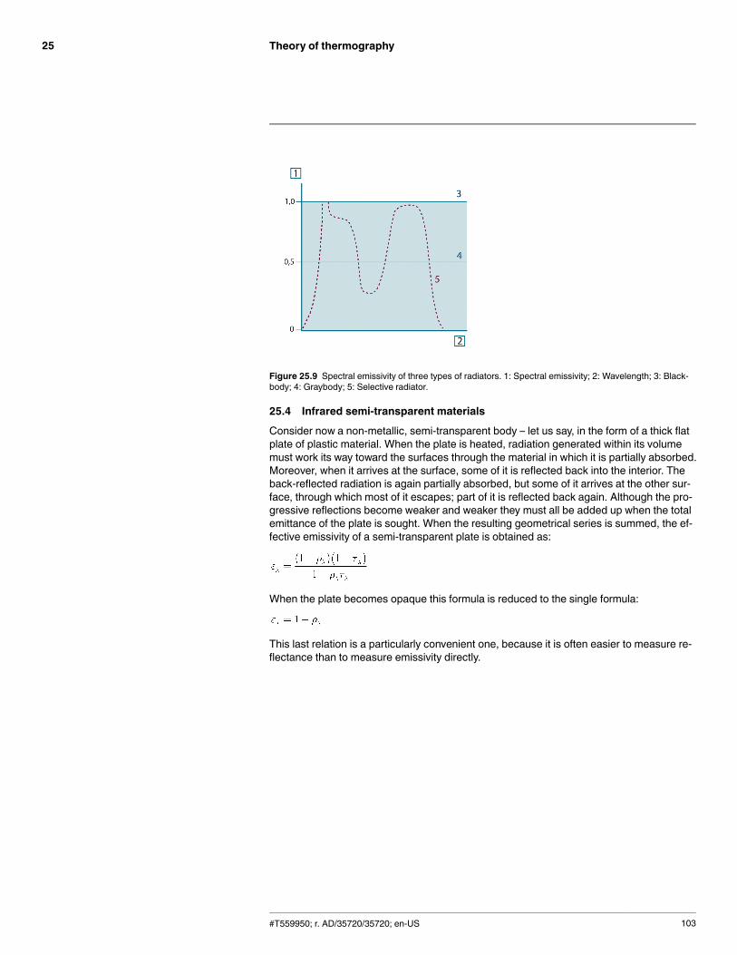
Theory of thermography25
Figure 25.9 Spectral emissivity of three types of radiators. 1: Spectral emissivity; 2: Wavelength; 3: Black-body; 4: Graybody; 5: Selective radiator.
25.4 Infrared semi-transparent materials
Consider now a non-metallic, semi-transparent body – let us say, in the form of a thick flatplate of plastic material. When the plate is heated, radiation generated within its volumemust work its way toward the surfaces through the material in which it is partially absorbed.Moreover, when it arrives at the surface, some of it is reflected back into the interior. Theback-reflected radiation is again partially absorbed, but some of it arrives at the other sur-face, through which most of it escapes; part of it is reflected back again. Although the pro-gressive reflections become weaker and weaker they must all be added up when the totalemittance of the plate is sought. When the resulting geometrical series is summed, the ef-fective emissivity of a semi-transparent plate is obtained as:
When the plate becomes opaque this formula is reduced to the single formula:
This last relation is a particularly convenient one, because it is often easier to measure re-flectance than to measure emissivity directly.
#T559950; r. AD/35720/35720; en-US 103
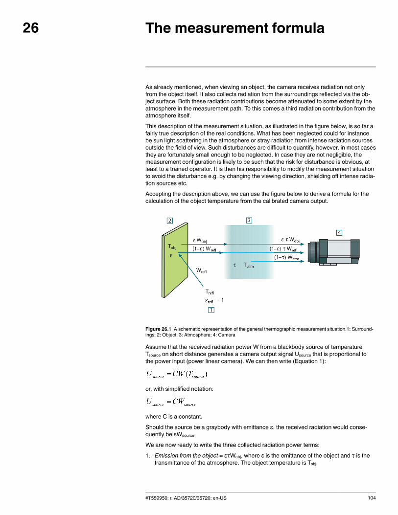
The measurement formula26
As already mentioned, when viewing an object, the camera receives radiation not onlyfrom the object itself. It also collects radiation from the surroundings reflected via the ob-ject surface. Both these radiation contributions become attenuated to some extent by theatmosphere in the measurement path. To this comes a third radiation contribution from theatmosphere itself.
This description of the measurement situation, as illustrated in the figure below, is so far afairly true description of the real conditions. What has been neglected could for instancebe sun light scattering in the atmosphere or stray radiation from intense radiation sourcesoutside the field of view. Such disturbances are difficult to quantify, however, in most casesthey are fortunately small enough to be neglected. In case they are not negligible, themeasurement configuration is likely to be such that the risk for disturbance is obvious, atleast to a trained operator. It is then his responsibility to modify the measurement situationto avoid the disturbance e.g. by changing the viewing direction, shielding off intense radia-tion sources etc.
Accepting the description above, we can use the figure below to derive a formula for thecalculation of the object temperature from the calibrated camera output.
Figure 26.1 A schematic representation of the general thermographic measurement situation.1: Surround-ings; 2: Object; 3: Atmosphere; 4: Camera
Assume that the received radiation power W from a blackbody source of temperatureTsource on short distance generates a camera output signal Usource that is proportional tothe power input (power linear camera). We can then write (Equation 1):
or, with simplified notation:
where C is a constant.
Should the source be a graybody with emittance ε, the received radiation would conse-quently be εWsource.
We are now ready to write the three collected radiation power terms:
1. Emission from the object = ετWobj, where ε is the emittance of the object and τ is thetransmittance of the atmosphere. The object temperature is Tobj.
#T559950; r. AD/35720/35720; en-US 104
The measurement formula26
2. Reflected emission from ambient sources = (1 – ε)τWrefl, where (1 – ε) is the reflec-tance of the object. The ambient sources have the temperature Trefl.It has here been assumed that the temperature Trefl is the same for all emitting surfaceswithin the halfsphere seen from a point on the object surface. This is of course some-times a simplification of the true situation. It is, however, a necessary simplification inorder to derive a workable formula, and Trefl can – at least theoretically – be given a val-ue that represents an efficient temperature of a complex surrounding.
Note also that we have assumed that the emittance for the surroundings = 1. This iscorrect in accordance with Kirchhoff’s law: All radiation impinging on the surroundingsurfaces will eventually be absorbed by the same surfaces. Thus the emittance = 1.(Note though that the latest discussion requires the complete sphere around the objectto be considered.)
3. Emission from the atmosphere = (1 – τ)τWatm, where (1 – τ) is the emittance of the at-mosphere. The temperature of the atmosphere is Tatm.
The total received radiation power can now be written (Equation 2):
We multiply each term by the constant C of Equation 1 and replace the CW products bythe corresponding U according to the same equation, and get (Equation 3):
Solve Equation 3 for Uobj (Equation 4):
This is the general measurement formula used in all the FLIR Systems thermographicequipment. The voltages of the formula are:Table 26.1 Voltages
Uobj Calculated camera output voltage for a blackbody of temperature Tobji.e. a voltage that can be directly converted into true requested objecttemperature.
Utot Measured camera output voltage for the actual case.
Urefl Theoretical camera output voltage for a blackbody of temperatureTrefl according to the calibration.
Uatm Theoretical camera output voltage for a blackbody of temperatureTatm according to the calibration.
The operator has to supply a number of parameter values for the calculation:
• the object emittance ε,• the relative humidity,• Tatm• object distance (Dobj)• the (effective) temperature of the object surroundings, or the reflected ambient temper-ature Trefl, and
• the temperature of the atmosphere TatmThis task could sometimes be a heavy burden for the operator since there are normally noeasy ways to find accurate values of emittance and atmospheric transmittance for the
#T559950; r. AD/35720/35720; en-US 105
The measurement formula26
actual case. The two temperatures are normally less of a problem provided the surround-ings do not contain large and intense radiation sources.
A natural question in this connection is: How important is it to know the right values ofthese parameters? It could though be of interest to get a feeling for this problem alreadyhere by looking into some different measurement cases and compare the relative magni-tudes of the three radiation terms. This will give indications about when it is important touse correct values of which parameters.
The figures below illustrates the relative magnitudes of the three radiation contributions forthree different object temperatures, two emittances, and two spectral ranges: SW and LW.Remaining parameters have the following fixed values:
• τ = 0.88• Trefl = +20°C (+68°F)• Tatm = +20°C (+68°F)
It is obvious that measurement of low object temperatures are more critical than measur-ing high temperatures since the ‘disturbing’ radiation sources are relatively much strongerin the first case. Should also the object emittance be low, the situation would be still moredifficult.
We have finally to answer a question about the importance of being allowed to use the cal-ibration curve above the highest calibration point, what we call extrapolation. Imagine thatwe in a certain case measure Utot = 4.5 volts. The highest calibration point for the camerawas in the order of 4.1 volts, a value unknown to the operator. Thus, even if the object hap-pened to be a blackbody, i.e. Uobj = Utot, we are actually performing extrapolation of thecalibration curve when converting 4.5 volts into temperature.
Let us now assume that the object is not black, it has an emittance of 0.75, and the trans-mittance is 0.92. We also assume that the two second terms of Equation 4 amount to 0.5volts together. Computation of Uobj by means of Equation 4 then results in Uobj = 4.5 / 0.75/ 0.92 – 0.5 = 6.0. This is a rather extreme extrapolation, particularly when considering thatthe video amplifier might limit the output to 5 volts! Note, though, that the application of thecalibration curve is a theoretical procedure where no electronic or other limitations exist.We trust that if there had been no signal limitations in the camera, and if it had been cali-brated far beyond 5 volts, the resulting curve would have been very much the same as ourreal curve extrapolated beyond 4.1 volts, provided the calibration algorithm is based on ra-diation physics, like the FLIR Systems algorithm. Of course there must be a limit to suchextrapolations.
#T559950; r. AD/35720/35720; en-US 106
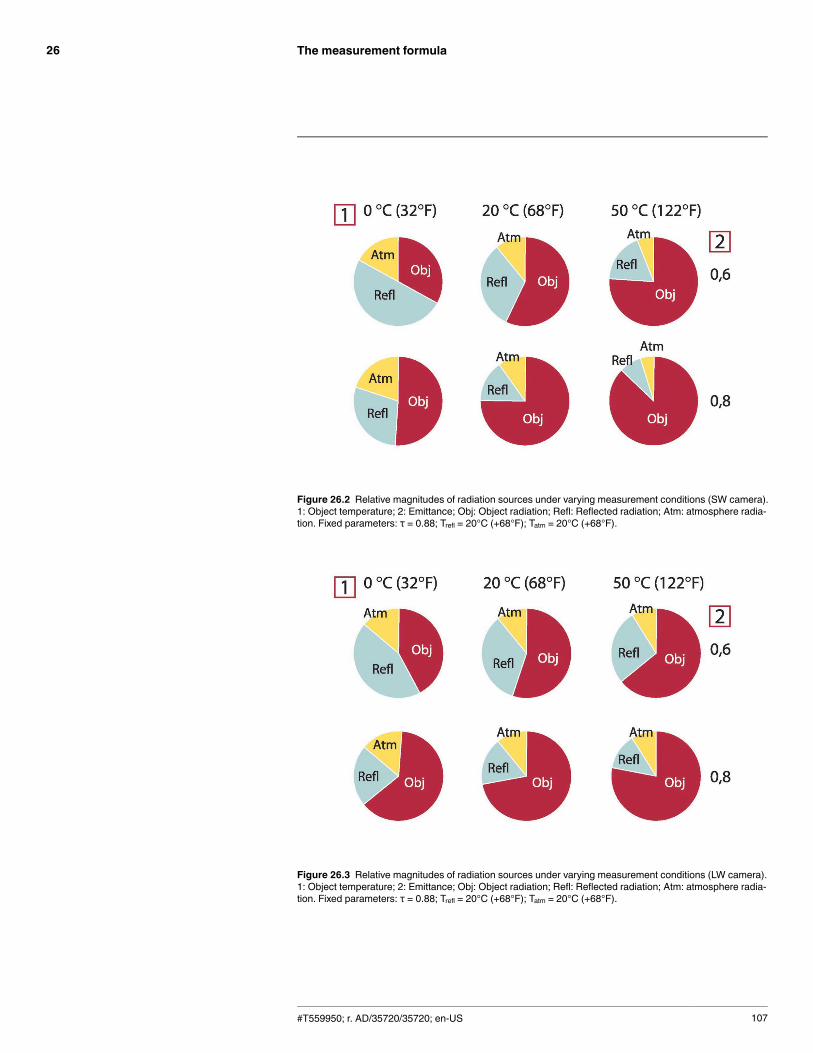
The measurement formula26
Figure 26.2 Relative magnitudes of radiation sources under varying measurement conditions (SW camera).1: Object temperature; 2: Emittance; Obj: Object radiation; Refl: Reflected radiation; Atm: atmosphere radia-tion. Fixed parameters: τ = 0.88; Trefl = 20°C (+68°F); Tatm = 20°C (+68°F).
Figure 26.3 Relative magnitudes of radiation sources under varying measurement conditions (LW camera).1: Object temperature; 2: Emittance; Obj: Object radiation; Refl: Reflected radiation; Atm: atmosphere radia-tion. Fixed parameters: τ = 0.88; Trefl = 20°C (+68°F); Tatm = 20°C (+68°F).
#T559950; r. AD/35720/35720; en-US 107

Emissivity tables27
This section presents a compilation of emissivity data from the infrared literature andmeasurements made by FLIR Systems.
27.1 References
1. Mikaél A. Bramson: Infrared Radiation, A Handbook for Applications, Plenum press, N.Y.
2. William L. Wolfe, George J. Zissis: The Infrared Handbook, Office of Naval Research,Department of Navy, Washington, D.C.
3. Madding, R. P.: Thermographic Instruments and systems. Madison, Wisconsin: Univer-sity of Wisconsin – Extension, Department of Engineering and Applied Science.
4. William L. Wolfe: Handbook of Military Infrared Technology, Office of Naval Research,Department of Navy, Washington, D.C.
5. Jones, Smith, Probert: External thermography of buildings..., Proc. of the Society ofPhoto-Optical Instrumentation Engineers, vol.110, Industrial and Civil Applications ofInfrared Technology, June 1977 London.
6. Paljak, Pettersson: Thermography of Buildings, Swedish Building Research Institute,Stockholm 1972.
7. Vlcek, J: Determination of emissivity with imaging radiometers and some emissivitiesat λ = 5 µm. Photogrammetric Engineering and Remote Sensing.
8. Kern: Evaluation of infrared emission of clouds and ground as measured by weathersatellites, Defence Documentation Center, AD 617 417.
9. Öhman, Claes: Emittansmätningar med AGEMA E-Box. Teknisk rapport, AGEMA1999. (Emittance measurements using AGEMA E-Box. Technical report, AGEMA1999.)
10. Matteï, S., Tang-Kwor, E: Emissivity measurements for Nextel Velvet coating 811-21between –36°C AND 82°C.
11. Lohrengel & Todtenhaupt (1996)12. ITC Technical publication 32.13. ITC Technical publication 29.14. Schuster, Norbert and Kolobrodov, Valentin G. Infrarotthermographie. Berlin: Wiley-
VCH, 2000.
Note The emissivity values in the table below are recorded using a shortwave (SW) cam-era. The values should be regarded as recommendations only and used with caution.
27.2 TablesTable 27.1 T: Total spectrum; SW: 2–5 µm; LW: 8–14 µm, LLW: 6.5–20 µm; 1: Material; 2: Specification; 3:Temperature in °C; 4: Spectrum; 5: Emissivity: 6:Reference
1 2 3 4 5 6
3M type 35 Vinyl electricaltape (severalcolors)
< 80 LW ≈ 0.96 13
3M type 88 Black vinyl electri-cal tape
< 105 LW ≈ 0.96 13
3M type 88 Black vinyl electri-cal tape
< 105 MW < 0.96 13
3M type Super 33+
Black vinyl electri-cal tape
< 80 LW ≈ 0.96 13
Aluminum anodized sheet 100 T 0.55 2
Aluminum anodized, black,dull
70 SW 0.67 9
#T559950; r. AD/35720/35720; en-US 108
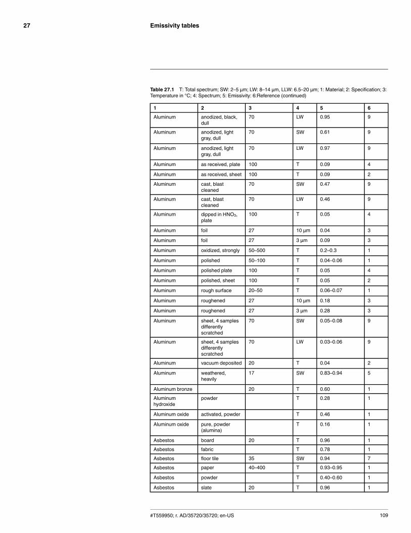
Emissivity tables27
Table 27.1 T: Total spectrum; SW: 2–5 µm; LW: 8–14 µm, LLW: 6.5–20 µm; 1: Material; 2: Specification; 3:Temperature in °C; 4: Spectrum; 5: Emissivity: 6:Reference (continued)
1 2 3 4 5 6
Aluminum anodized, black,dull
70 LW 0.95 9
Aluminum anodized, lightgray, dull
70 SW 0.61 9
Aluminum anodized, lightgray, dull
70 LW 0.97 9
Aluminum as received, plate 100 T 0.09 4
Aluminum as received, sheet 100 T 0.09 2
Aluminum cast, blastcleaned
70 SW 0.47 9
Aluminum cast, blastcleaned
70 LW 0.46 9
Aluminum dipped in HNO3,plate
100 T 0.05 4
Aluminum foil 27 10 µm 0.04 3
Aluminum foil 27 3 µm 0.09 3
Aluminum oxidized, strongly 50–500 T 0.2–0.3 1
Aluminum polished 50–100 T 0.04–0.06 1
Aluminum polished plate 100 T 0.05 4
Aluminum polished, sheet 100 T 0.05 2
Aluminum rough surface 20–50 T 0.06–0.07 1
Aluminum roughened 27 10 µm 0.18 3
Aluminum roughened 27 3 µm 0.28 3
Aluminum sheet, 4 samplesdifferentlyscratched
70 SW 0.05–0.08 9
Aluminum sheet, 4 samplesdifferentlyscratched
70 LW 0.03–0.06 9
Aluminum vacuum deposited 20 T 0.04 2
Aluminum weathered,heavily
17 SW 0.83–0.94 5
Aluminum bronze 20 T 0.60 1
Aluminumhydroxide
powder T 0.28 1
Aluminum oxide activated, powder T 0.46 1
Aluminum oxide pure, powder(alumina)
T 0.16 1
Asbestos board 20 T 0.96 1
Asbestos fabric T 0.78 1
Asbestos floor tile 35 SW 0.94 7
Asbestos paper 40–400 T 0.93–0.95 1
Asbestos powder T 0.40–0.60 1
Asbestos slate 20 T 0.96 1
#T559950; r. AD/35720/35720; en-US 109
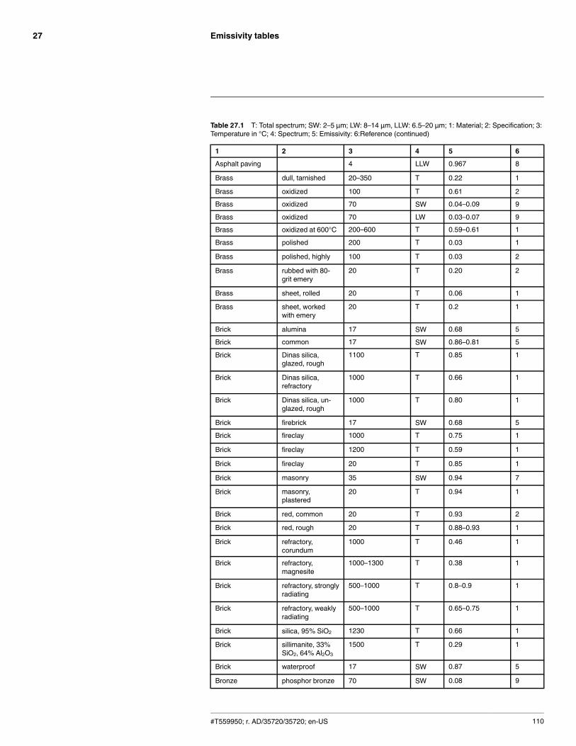
Emissivity tables27
Table 27.1 T: Total spectrum; SW: 2–5 µm; LW: 8–14 µm, LLW: 6.5–20 µm; 1: Material; 2: Specification; 3:Temperature in °C; 4: Spectrum; 5: Emissivity: 6:Reference (continued)
1 2 3 4 5 6
Asphalt paving 4 LLW 0.967 8
Brass dull, tarnished 20–350 T 0.22 1
Brass oxidized 100 T 0.61 2
Brass oxidized 70 SW 0.04–0.09 9
Brass oxidized 70 LW 0.03–0.07 9
Brass oxidized at 600°C 200–600 T 0.59–0.61 1
Brass polished 200 T 0.03 1
Brass polished, highly 100 T 0.03 2
Brass rubbed with 80-grit emery
20 T 0.20 2
Brass sheet, rolled 20 T 0.06 1
Brass sheet, workedwith emery
20 T 0.2 1
Brick alumina 17 SW 0.68 5
Brick common 17 SW 0.86–0.81 5
Brick Dinas silica,glazed, rough
1100 T 0.85 1
Brick Dinas silica,refractory
1000 T 0.66 1
Brick Dinas silica, un-glazed, rough
1000 T 0.80 1
Brick firebrick 17 SW 0.68 5
Brick fireclay 1000 T 0.75 1
Brick fireclay 1200 T 0.59 1
Brick fireclay 20 T 0.85 1
Brick masonry 35 SW 0.94 7
Brick masonry,plastered
20 T 0.94 1
Brick red, common 20 T 0.93 2
Brick red, rough 20 T 0.88–0.93 1
Brick refractory,corundum
1000 T 0.46 1
Brick refractory,magnesite
1000–1300 T 0.38 1
Brick refractory, stronglyradiating
500–1000 T 0.8–0.9 1
Brick refractory, weaklyradiating
500–1000 T 0.65–0.75 1
Brick silica, 95% SiO2 1230 T 0.66 1
Brick sillimanite, 33%SiO2, 64% Al2O3
1500 T 0.29 1
Brick waterproof 17 SW 0.87 5
Bronze phosphor bronze 70 SW 0.08 9
#T559950; r. AD/35720/35720; en-US 110
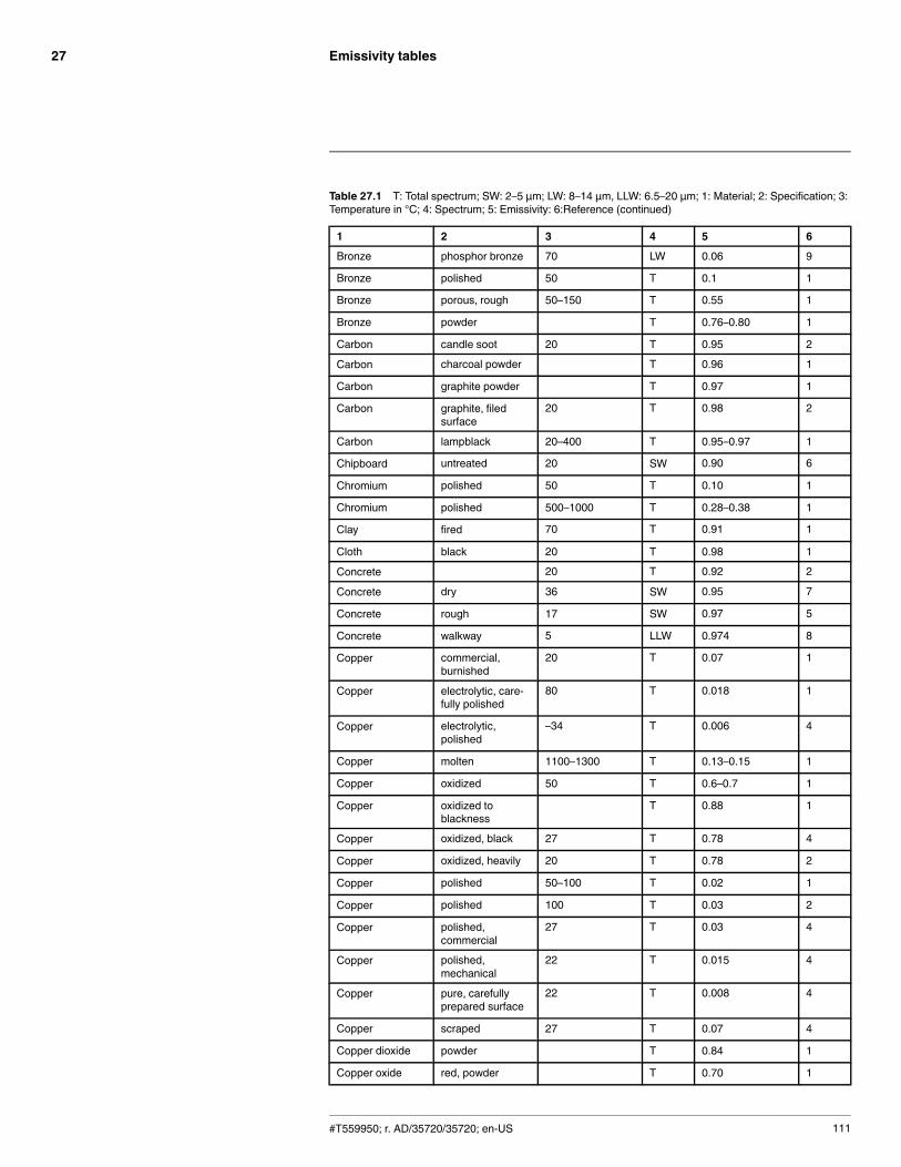
Emissivity tables27
Table 27.1 T: Total spectrum; SW: 2–5 µm; LW: 8–14 µm, LLW: 6.5–20 µm; 1: Material; 2: Specification; 3:Temperature in °C; 4: Spectrum; 5: Emissivity: 6:Reference (continued)
1 2 3 4 5 6
Bronze phosphor bronze 70 LW 0.06 9
Bronze polished 50 T 0.1 1
Bronze porous, rough 50–150 T 0.55 1
Bronze powder T 0.76–0.80 1
Carbon candle soot 20 T 0.95 2
Carbon charcoal powder T 0.96 1
Carbon graphite powder T 0.97 1
Carbon graphite, filedsurface
20 T 0.98 2
Carbon lampblack 20–400 T 0.95–0.97 1
Chipboard untreated 20 SW 0.90 6
Chromium polished 50 T 0.10 1
Chromium polished 500–1000 T 0.28–0.38 1
Clay fired 70 T 0.91 1
Cloth black 20 T 0.98 1
Concrete 20 T 0.92 2
Concrete dry 36 SW 0.95 7
Concrete rough 17 SW 0.97 5
Concrete walkway 5 LLW 0.974 8
Copper commercial,burnished
20 T 0.07 1
Copper electrolytic, care-fully polished
80 T 0.018 1
Copper electrolytic,polished
–34 T 0.006 4
Copper molten 1100–1300 T 0.13–0.15 1
Copper oxidized 50 T 0.6–0.7 1
Copper oxidized toblackness
T 0.88 1
Copper oxidized, black 27 T 0.78 4
Copper oxidized, heavily 20 T 0.78 2
Copper polished 50–100 T 0.02 1
Copper polished 100 T 0.03 2
Copper polished,commercial
27 T 0.03 4
Copper polished,mechanical
22 T 0.015 4
Copper pure, carefullyprepared surface
22 T 0.008 4
Copper scraped 27 T 0.07 4
Copper dioxide powder T 0.84 1
Copper oxide red, powder T 0.70 1
#T559950; r. AD/35720/35720; en-US 111
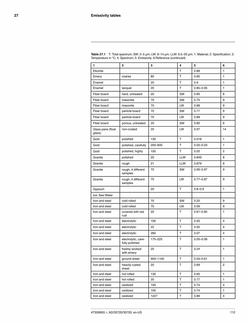
Emissivity tables27
Table 27.1 T: Total spectrum; SW: 2–5 µm; LW: 8–14 µm, LLW: 6.5–20 µm; 1: Material; 2: Specification; 3:Temperature in °C; 4: Spectrum; 5: Emissivity: 6:Reference (continued)
1 2 3 4 5 6
Ebonite T 0.89 1
Emery coarse 80 T 0.85 1
Enamel 20 T 0.9 1
Enamel lacquer 20 T 0.85–0.95 1
Fiber board hard, untreated 20 SW 0.85 6
Fiber board masonite 70 SW 0.75 9
Fiber board masonite 70 LW 0.88 9
Fiber board particle board 70 SW 0.77 9
Fiber board particle board 70 LW 0.89 9
Fiber board porous, untreated 20 SW 0.85 6
Glass pane (floatglass)
non-coated 20 LW 0.97 14
Gold polished 130 T 0.018 1
Gold polished, carefully 200–600 T 0.02–0.03 1
Gold polished, highly 100 T 0.02 2
Granite polished 20 LLW 0.849 8
Granite rough 21 LLW 0.879 8
Granite rough, 4 differentsamples
70 SW 0.95–0.97 9
Granite rough, 4 differentsamples
70 LW 0.77–0.87 9
Gypsum 20 T 0.8–0.9 1
Ice: See Water
Iron and steel cold rolled 70 SW 0.20 9
Iron and steel cold rolled 70 LW 0.09 9
Iron and steel covered with redrust
20 T 0.61–0.85 1
Iron and steel electrolytic 100 T 0.05 4
Iron and steel electrolytic 22 T 0.05 4
Iron and steel electrolytic 260 T 0.07 4
Iron and steel electrolytic, care-fully polished
175–225 T 0.05–0.06 1
Iron and steel freshly workedwith emery
20 T 0.24 1
Iron and steel ground sheet 950–1100 T 0.55–0.61 1
Iron and steel heavily rustedsheet
20 T 0.69 2
Iron and steel hot rolled 130 T 0.60 1
Iron and steel hot rolled 20 T 0.77 1
Iron and steel oxidized 100 T 0.74 4
Iron and steel oxidized 100 T 0.74 1
Iron and steel oxidized 1227 T 0.89 4
#T559950; r. AD/35720/35720; en-US 112
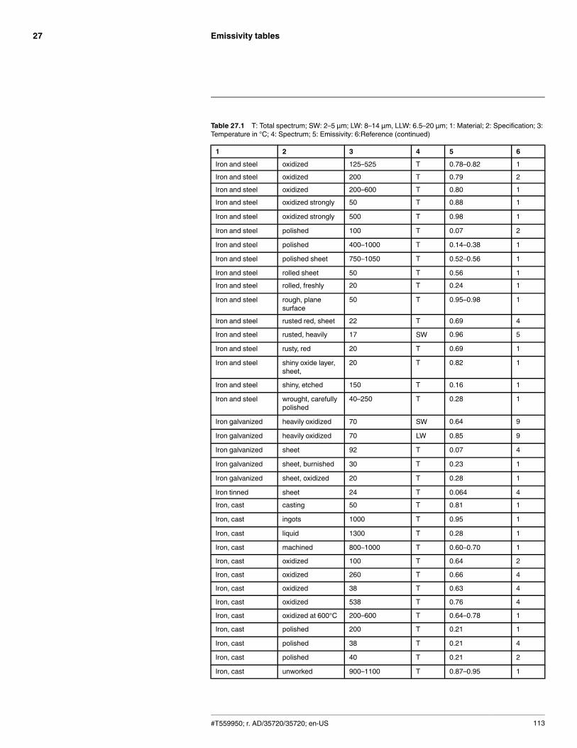
Emissivity tables27
Table 27.1 T: Total spectrum; SW: 2–5 µm; LW: 8–14 µm, LLW: 6.5–20 µm; 1: Material; 2: Specification; 3:Temperature in °C; 4: Spectrum; 5: Emissivity: 6:Reference (continued)
1 2 3 4 5 6
Iron and steel oxidized 125–525 T 0.78–0.82 1
Iron and steel oxidized 200 T 0.79 2
Iron and steel oxidized 200–600 T 0.80 1
Iron and steel oxidized strongly 50 T 0.88 1
Iron and steel oxidized strongly 500 T 0.98 1
Iron and steel polished 100 T 0.07 2
Iron and steel polished 400–1000 T 0.14–0.38 1
Iron and steel polished sheet 750–1050 T 0.52–0.56 1
Iron and steel rolled sheet 50 T 0.56 1
Iron and steel rolled, freshly 20 T 0.24 1
Iron and steel rough, planesurface
50 T 0.95–0.98 1
Iron and steel rusted red, sheet 22 T 0.69 4
Iron and steel rusted, heavily 17 SW 0.96 5
Iron and steel rusty, red 20 T 0.69 1
Iron and steel shiny oxide layer,sheet,
20 T 0.82 1
Iron and steel shiny, etched 150 T 0.16 1
Iron and steel wrought, carefullypolished
40–250 T 0.28 1
Iron galvanized heavily oxidized 70 SW 0.64 9
Iron galvanized heavily oxidized 70 LW 0.85 9
Iron galvanized sheet 92 T 0.07 4
Iron galvanized sheet, burnished 30 T 0.23 1
Iron galvanized sheet, oxidized 20 T 0.28 1
Iron tinned sheet 24 T 0.064 4
Iron, cast casting 50 T 0.81 1
Iron, cast ingots 1000 T 0.95 1
Iron, cast liquid 1300 T 0.28 1
Iron, cast machined 800–1000 T 0.60–0.70 1
Iron, cast oxidized 100 T 0.64 2
Iron, cast oxidized 260 T 0.66 4
Iron, cast oxidized 38 T 0.63 4
Iron, cast oxidized 538 T 0.76 4
Iron, cast oxidized at 600°C 200–600 T 0.64–0.78 1
Iron, cast polished 200 T 0.21 1
Iron, cast polished 38 T 0.21 4
Iron, cast polished 40 T 0.21 2
Iron, cast unworked 900–1100 T 0.87–0.95 1
#T559950; r. AD/35720/35720; en-US 113
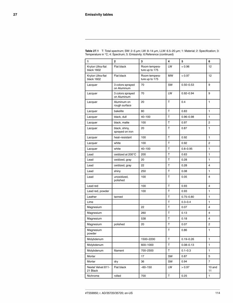
Emissivity tables27
Table 27.1 T: Total spectrum; SW: 2–5 µm; LW: 8–14 µm, LLW: 6.5–20 µm; 1: Material; 2: Specification; 3:Temperature in °C; 4: Spectrum; 5: Emissivity: 6:Reference (continued)
1 2 3 4 5 6
Krylon Ultra-flatblack 1602
Flat black Room tempera-ture up to 175
LW ≈ 0.96 12
Krylon Ultra-flatblack 1602
Flat black Room tempera-ture up to 175
MW ≈ 0.97 12
Lacquer 3 colors sprayedon Aluminum
70 SW 0.50–0.53 9
Lacquer 3 colors sprayedon Aluminum
70 LW 0.92–0.94 9
Lacquer Aluminum onrough surface
20 T 0.4 1
Lacquer bakelite 80 T 0.83 1
Lacquer black, dull 40–100 T 0.96–0.98 1
Lacquer black, matte 100 T 0.97 2
Lacquer black, shiny,sprayed on iron
20 T 0.87 1
Lacquer heat–resistant 100 T 0.92 1
Lacquer white 100 T 0.92 2
Lacquer white 40–100 T 0.8–0.95 1
Lead oxidized at 200°C 200 T 0.63 1
Lead oxidized, gray 20 T 0.28 1
Lead oxidized, gray 22 T 0.28 4
Lead shiny 250 T 0.08 1
Lead unoxidized,polished
100 T 0.05 4
Lead red 100 T 0.93 4
Lead red, powder 100 T 0.93 1
Leather tanned T 0.75–0.80 1
Lime T 0.3–0.4 1
Magnesium 22 T 0.07 4
Magnesium 260 T 0.13 4
Magnesium 538 T 0.18 4
Magnesium polished 20 T 0.07 2
Magnesiumpowder
T 0.86 1
Molybdenum 1500–2200 T 0.19–0.26 1
Molybdenum 600–1000 T 0.08–0.13 1
Molybdenum filament 700–2500 T 0.1–0.3 1
Mortar 17 SW 0.87 5
Mortar dry 36 SW 0.94 7
Nextel Velvet 811-21 Black
Flat black –60–150 LW > 0.97 10 and11
Nichrome rolled 700 T 0.25 1
#T559950; r. AD/35720/35720; en-US 114
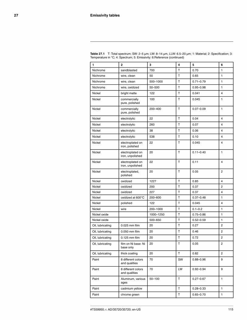
Emissivity tables27
Table 27.1 T: Total spectrum; SW: 2–5 µm; LW: 8–14 µm, LLW: 6.5–20 µm; 1: Material; 2: Specification; 3:Temperature in °C; 4: Spectrum; 5: Emissivity: 6:Reference (continued)
1 2 3 4 5 6
Nichrome sandblasted 700 T 0.70 1
Nichrome wire, clean 50 T 0.65 1
Nichrome wire, clean 500–1000 T 0.71–0.79 1
Nichrome wire, oxidized 50–500 T 0.95–0.98 1
Nickel bright matte 122 T 0.041 4
Nickel commerciallypure, polished
100 T 0.045 1
Nickel commerciallypure, polished
200–400 T 0.07–0.09 1
Nickel electrolytic 22 T 0.04 4
Nickel electrolytic 260 T 0.07 4
Nickel electrolytic 38 T 0.06 4
Nickel electrolytic 538 T 0.10 4
Nickel electroplated oniron, polished
22 T 0.045 4
Nickel electroplated oniron, unpolished
20 T 0.11–0.40 1
Nickel electroplated oniron, unpolished
22 T 0.11 4
Nickel electroplated,polished
20 T 0.05 2
Nickel oxidized 1227 T 0.85 4
Nickel oxidized 200 T 0.37 2
Nickel oxidized 227 T 0.37 4
Nickel oxidized at 600°C 200–600 T 0.37–0.48 1
Nickel polished 122 T 0.045 4
Nickel wire 200–1000 T 0.1–0.2 1
Nickel oxide 1000–1250 T 0.75–0.86 1
Nickel oxide 500–650 T 0.52–0.59 1
Oil, lubricating 0.025 mm film 20 T 0.27 2
Oil, lubricating 0.050 mm film 20 T 0.46 2
Oil, lubricating 0.125 mm film 20 T 0.72 2
Oil, lubricating film on Ni base: Nibase only
20 T 0.05 2
Oil, lubricating thick coating 20 T 0.82 2
Paint 8 different colorsand qualities
70 SW 0.88–0.96 9
Paint 8 different colorsand qualities
70 LW 0.92–0.94 9
Paint Aluminum, variousages
50–100 T 0.27–0.67 1
Paint cadmium yellow T 0.28–0.33 1
Paint chrome green T 0.65–0.70 1
#T559950; r. AD/35720/35720; en-US 115
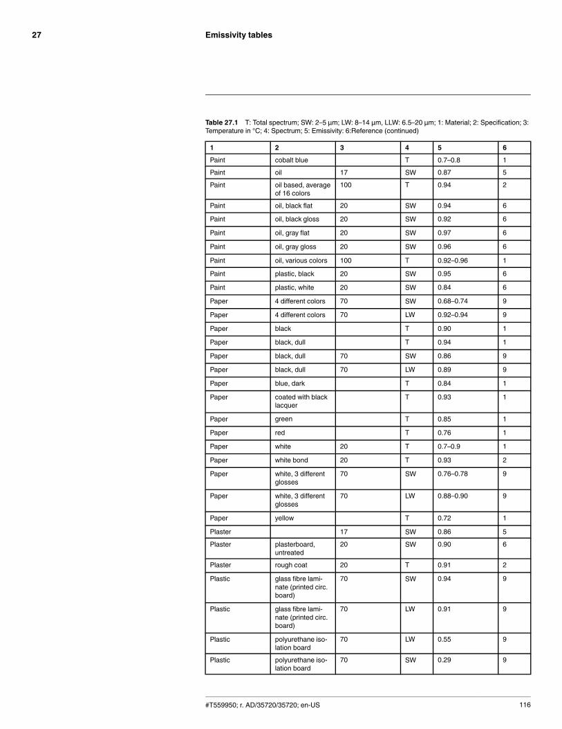
Emissivity tables27
Table 27.1 T: Total spectrum; SW: 2–5 µm; LW: 8–14 µm, LLW: 6.5–20 µm; 1: Material; 2: Specification; 3:Temperature in °C; 4: Spectrum; 5: Emissivity: 6:Reference (continued)
1 2 3 4 5 6
Paint cobalt blue T 0.7–0.8 1
Paint oil 17 SW 0.87 5
Paint oil based, averageof 16 colors
100 T 0.94 2
Paint oil, black flat 20 SW 0.94 6
Paint oil, black gloss 20 SW 0.92 6
Paint oil, gray flat 20 SW 0.97 6
Paint oil, gray gloss 20 SW 0.96 6
Paint oil, various colors 100 T 0.92–0.96 1
Paint plastic, black 20 SW 0.95 6
Paint plastic, white 20 SW 0.84 6
Paper 4 different colors 70 SW 0.68–0.74 9
Paper 4 different colors 70 LW 0.92–0.94 9
Paper black T 0.90 1
Paper black, dull T 0.94 1
Paper black, dull 70 SW 0.86 9
Paper black, dull 70 LW 0.89 9
Paper blue, dark T 0.84 1
Paper coated with blacklacquer
T 0.93 1
Paper green T 0.85 1
Paper red T 0.76 1
Paper white 20 T 0.7–0.9 1
Paper white bond 20 T 0.93 2
Paper white, 3 differentglosses
70 SW 0.76–0.78 9
Paper white, 3 differentglosses
70 LW 0.88–0.90 9
Paper yellow T 0.72 1
Plaster 17 SW 0.86 5
Plaster plasterboard,untreated
20 SW 0.90 6
Plaster rough coat 20 T 0.91 2
Plastic glass fibre lami-nate (printed circ.board)
70 SW 0.94 9
Plastic glass fibre lami-nate (printed circ.board)
70 LW 0.91 9
Plastic polyurethane iso-lation board
70 LW 0.55 9
Plastic polyurethane iso-lation board
70 SW 0.29 9
#T559950; r. AD/35720/35720; en-US 116
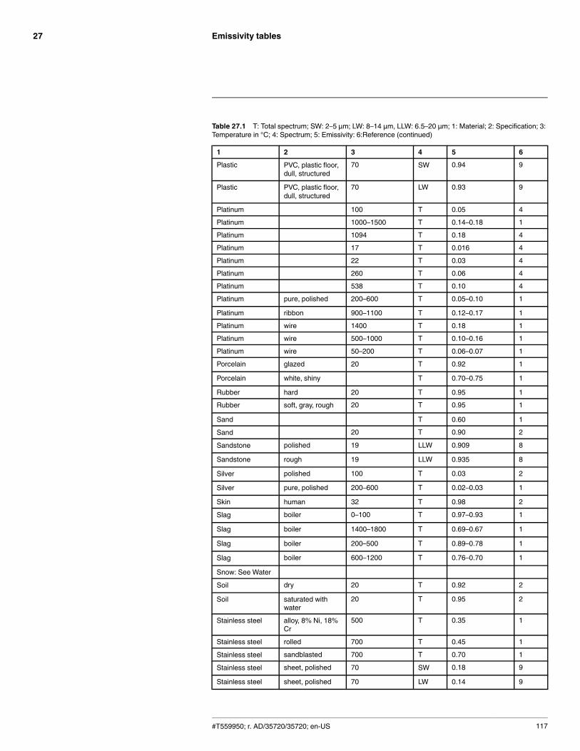
Emissivity tables27
Table 27.1 T: Total spectrum; SW: 2–5 µm; LW: 8–14 µm, LLW: 6.5–20 µm; 1: Material; 2: Specification; 3:Temperature in °C; 4: Spectrum; 5: Emissivity: 6:Reference (continued)
1 2 3 4 5 6
Plastic PVC, plastic floor,dull, structured
70 SW 0.94 9
Plastic PVC, plastic floor,dull, structured
70 LW 0.93 9
Platinum 100 T 0.05 4
Platinum 1000–1500 T 0.14–0.18 1
Platinum 1094 T 0.18 4
Platinum 17 T 0.016 4
Platinum 22 T 0.03 4
Platinum 260 T 0.06 4
Platinum 538 T 0.10 4
Platinum pure, polished 200–600 T 0.05–0.10 1
Platinum ribbon 900–1100 T 0.12–0.17 1
Platinum wire 1400 T 0.18 1
Platinum wire 500–1000 T 0.10–0.16 1
Platinum wire 50–200 T 0.06–0.07 1
Porcelain glazed 20 T 0.92 1
Porcelain white, shiny T 0.70–0.75 1
Rubber hard 20 T 0.95 1
Rubber soft, gray, rough 20 T 0.95 1
Sand T 0.60 1
Sand 20 T 0.90 2
Sandstone polished 19 LLW 0.909 8
Sandstone rough 19 LLW 0.935 8
Silver polished 100 T 0.03 2
Silver pure, polished 200–600 T 0.02–0.03 1
Skin human 32 T 0.98 2
Slag boiler 0–100 T 0.97–0.93 1
Slag boiler 1400–1800 T 0.69–0.67 1
Slag boiler 200–500 T 0.89–0.78 1
Slag boiler 600–1200 T 0.76–0.70 1
Snow: See Water
Soil dry 20 T 0.92 2
Soil saturated withwater
20 T 0.95 2
Stainless steel alloy, 8% Ni, 18%Cr
500 T 0.35 1
Stainless steel rolled 700 T 0.45 1
Stainless steel sandblasted 700 T 0.70 1
Stainless steel sheet, polished 70 SW 0.18 9
Stainless steel sheet, polished 70 LW 0.14 9
#T559950; r. AD/35720/35720; en-US 117

Emissivity tables27
Table 27.1 T: Total spectrum; SW: 2–5 µm; LW: 8–14 µm, LLW: 6.5–20 µm; 1: Material; 2: Specification; 3:Temperature in °C; 4: Spectrum; 5: Emissivity: 6:Reference (continued)
1 2 3 4 5 6
Stainless steel sheet, untreated,somewhatscratched
70 SW 0.30 9
Stainless steel sheet, untreated,somewhatscratched
70 LW 0.28 9
Stainless steel type 18-8, buffed 20 T 0.16 2
Stainless steel type 18-8, oxi-dized at 800°C
60 T 0.85 2
Stucco rough, lime 10–90 T 0.91 1
Styrofoam insulation 37 SW 0.60 7
Tar T 0.79–0.84 1
Tar paper 20 T 0.91–0.93 1
Tile glazed 17 SW 0.94 5
Tin burnished 20–50 T 0.04–0.06 1
Tin tin–plated sheetiron
100 T 0.07 2
Titanium oxidized at 540°C 1000 T 0.60 1
Titanium oxidized at 540°C 200 T 0.40 1
Titanium oxidized at 540°C 500 T 0.50 1
Titanium polished 1000 T 0.36 1
Titanium polished 200 T 0.15 1
Titanium polished 500 T 0.20 1
Tungsten 1500–2200 T 0.24–0.31 1
Tungsten 200 T 0.05 1
Tungsten 600–1000 T 0.1–0.16 1
Tungsten filament 3300 T 0.39 1
Varnish flat 20 SW 0.93 6
Varnish on oak parquetfloor
70 SW 0.90 9
Varnish on oak parquetfloor
70 LW 0.90–0.93 9
Wallpaper slight pattern, lightgray
20 SW 0.85 6
Wallpaper slight pattern, red 20 SW 0.90 6
Water distilled 20 T 0.96 2
Water frost crystals –10 T 0.98 2
Water ice, covered withheavy frost
0 T 0.98 1
Water ice, smooth 0 T 0.97 1
Water ice, smooth –10 T 0.96 2
Water layer >0.1 mmthick
0–100 T 0.95–0.98 1
Water snow T 0.8 1
#T559950; r. AD/35720/35720; en-US 118
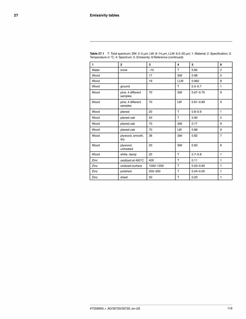
Emissivity tables27
Table 27.1 T: Total spectrum; SW: 2–5 µm; LW: 8–14 µm, LLW: 6.5–20 µm; 1: Material; 2: Specification; 3:Temperature in °C; 4: Spectrum; 5: Emissivity: 6:Reference (continued)
1 2 3 4 5 6
Water snow –10 T 0.85 2
Wood 17 SW 0.98 5
Wood 19 LLW 0.962 8
Wood ground T 0.5–0.7 1
Wood pine, 4 differentsamples
70 SW 0.67–0.75 9
Wood pine, 4 differentsamples
70 LW 0.81–0.89 9
Wood planed 20 T 0.8–0.9 1
Wood planed oak 20 T 0.90 2
Wood planed oak 70 SW 0.77 9
Wood planed oak 70 LW 0.88 9
Wood plywood, smooth,dry
36 SW 0.82 7
Wood plywood,untreated
20 SW 0.83 6
Wood white, damp 20 T 0.7–0.8 1
Zinc oxidized at 400°C 400 T 0.11 1
Zinc oxidized surface 1000–1200 T 0.50–0.60 1
Zinc polished 200–300 T 0.04–0.05 1
Zinc sheet 50 T 0.20 1
#T559950; r. AD/35720/35720; en-US 119
A note on the technical production of this publicationThis publication was produced using XML — the eXtensible Markup Language. For more information aboutXML, please visit http://www.w3.org/XML/A note on the typeface used in this publicationThis publication was typeset using Linotype Helvetica™World. Helvetica™ was designed by Max Miedinger(1910–1980)LOEF (List Of Effective Files)T501090.xml; en-US; AD; 35720; 2016-05-19T505475.xml; en-US; 15550; 2014-06-30T505780.xml; en-US; 33259; 2016-02-10T505469.xml; en-US; 23215; 2015-02-19T505013.xml; en-US; 35155; 2016-04-21T505794.xml; en-US; 30706; 2015-11-24T505476.xml; en-US; 11926; 2014-02-20T505007.xml; en-US; 35155; 2016-04-21T505004.xml; en-US; 35155; 2016-04-21T505000.xml; en-US; 35155; 2016-04-21T505005.xml; en-US; 35155; 2016-04-21T505001.xml; en-US; 32554; 2016-01-20T505006.xml; en-US; 32555; 2016-01-20T505002.xml; en-US; 33518; 2016-02-18
#T559950; r. AD/35720/35720; en-US 120

last page
Publ. No.: T559950Release: ADCommit: 35720Head: 35720Language: en-USModified: 2016-05-19Formatted: 2016-05-19
Websitehttp://www.flir.comCustomer supporthttp://support.flir.comCopyright© 2016, FLIR Systems, Inc. All rights reserved worldwide.DisclaimerSpecifications subject to change without further notice. Models and accessories subject to regional market considerations. License procedures may apply. Productsdescribed herein may be subject to US Export Regulations. Please refer to [email protected] with any questions.
![English Language Arts and Reading 7–12 (231) Preparation ...English Language Proficiency Standards [ELPS]) and students with reading, writing or oral language difficulties and/or](https://static.documents.pub/doc/80x56/5e80a4bff0fbbd229f7ca8d3/english-language-arts-and-reading-7a12-231-preparation-english-language.jpg)


