79
User’s Manual of Compressor
User’s Manual of Compressor

The user s manual is prepared, based on GRH3-100A.
Read this manual carefully before installing and operating the compressorand use it properly.
In addition, after reading this manual, keep it close to the compressor forfuture reference such as repair, maintenance or trouble.
DANGER
Be sure to check airend rotating directionwhen operating the compressor for thefirst time after installation. If it rotates in the opposite direction, theairend can be damaged.
Be sure to check therotating direction !

3
Thank you for purchasing Hanshin Compressor. Hanshin Screw Compressor is the productdeveloped by our long history, abundant experience and accumulated technology.
The screw compressor has been verified for the performance by examined design andappropriate reliability test and is conveniently programmed to be optimally operated when thecontrol-related data are automatically calculated and changed if a user simply changes theoperation pressure by Micom s control almost close to AI.
The function guarantees that the compressor operates optimally, so the company assures of highperformance, highly evaluated from users.
Every machine and controller may show 100% of the performance as long as it isclearlyunderstood and well maintained. Please read this manual carefully before use.
GRH3 star-delta User’s Manual
Preface

4 / Hanshin
Contents
About how to use the manual
1. About Safety
2. Names of Parts
3. Electric Wiring
4. Installation and Piping
5. Operations
6. Troubleshooting
7. Maintenance
8. Control System
9. Specifications
10. Maintenance Checklist
11. Operation Log
12. Quality Warranty
13. Outside Drawing by Models
1-1 General Cautions1-2 About Marks and Symbols1-3 Check Caution/Warning Label1-4 Safety Rules1-5 Installation Place and Cautions for Installation1-6 Cautions for Electric Wiring1-7 Cautions for Operation1-8 Cautions for Stoppage1-9 Cautions for Maintenance
2-1 GRH3-20A, 25A, 30A, 35A, 50A2-2 GRH3-75A, 100A
3-1 Wiring3-2 Power Facilities
4-1 Identification of the product specifications4-2 Cautions for Transportation4-3 Cautions for Installation4-4 Cautions for Piping
5-1 Micom Controller5-2 Operation Control5-3 Initial Operation & Routine Operation5-4 Schedule Operation5-5 Remote operation5-6 Remote Monitoring System[Micom]5-7 Remote Monitoring System[Computer]5-8 Micom Display Configuration & Operations 5-9 Operation Data Setup and Check
6-1 Protective Devices and LCD Message List6-2 Trouble Causes and Measures
7-1 Regular Maintenance7-2 Maintenance Method
8-1 Compressor Configuration Layout8-2 Control Circuit8-3 Operation Flow Chart8-4 Arrangement Diagram and Spec. of Control Parts
5
667111314151717
1820
2224
25252630
333536394041424344
5152
5758
60616567
70
71
72
73
74
GRH3 star-delta User’s Manual

5
About how to use the manual
The screw compressor is intended to be used domestically (the Republic of Korea).
The manual describes the routine operation, repair and maintenance of the manual as well as theinstallation, general management and periodic maintenance of it.
Before installing the compressor, carefully read this manual, fully understand it and follow the description. Also, keep this manual handy for future reference.
If you find any doubtful content in the manual, please contact your dealer or the company s A/S servicecenter(TEL.031-494-8484).
Type Explanation
The informative plate as model, serial number, operation pressure and voltage is attached on the left side ofthe compressor. Please fill it for your regular maintenance and parts order.
GRH3 - 100 A
Output (HP)
Air cooling : A / Water cooling type : W
MODEL
SERIAL NO
WORK PRESSURE
VOLTAGE
MANUFACTURING
Do not directly inhale compressor air nor use it for machines designed for therespiratory organs. Direct inhalation may cause dangerous unexpected accidents such as dyspne
Warning
GRH3 star-delta User’s Manual
6 / Hanshin
About how to use the manual 1. About Safety
1. About Safety
For the safety purpose, read the cautions and warnings specified in the manual carefully and fullyunderstand them for proper use. The chapter especially highlights the safety items.
1-1 General Cautions
The installation, operation, preservation, repair and other works of the product should be executed by acompetent engineer.
If a user adds a control circuit to the product or attempt to modify or alter the product without permission,it may cause physical injuries or damages on the product due to the malfunction of the protective devices,which may not be covered by the warranty. At the moment, the product may be repaired by our payservice.
Do not use the compressed air of the compressor for direct inhalation or air supply source of therespiratory organs. It may cause dangerously physical injuries.
[Warning] or [Caution] in the manual contains important information that should be always followed.
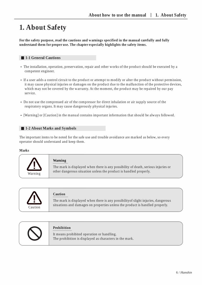
1-2 About Marks and Symbols
The important items to be noted for the safe use and trouble avoidance are marked as below, so everyoperator should understand and keep them.
Marks
Warning
The mark is displayed when there is any possibility of death, serious injuries orother dangerous situation unless the product is handled properly.Warning
Caution
The mark is displayed when there is any possibilityof slight injuries, dangeroussituations and damages on properties unless the product is handled properly. Caution
Prohibition
It means prohibited operation or handling. The prohibition is displayed as characters in the mark.

7
Caution
Electric shock The power should be off before checking the electricbox because of the danger of electric shock. After turning it off, a sign, “Power-off for check”should be indicated to avoid accident.
Caution
Discharge pressure ejection When checking/replacing parts, the compressorshould stop with the pressure set to 0 A special attention should be paid around a safevalve because it may work during operation.
Warning
Be careful of being rolled by rotation Do not touch yourself or other articles on anyrotating parts such as main/fan motor. The power should be off before repair,maintenance and other works
Caution
Beware of a scald Oil cooler, air end and tank may be very hot duringor just after operation, probably causing a scald. When working around any heating source, youshould wait until it is cooled after turn-off
1-3 Check Caution/Warning Label
1. GRH3-20A, 25A, 30A, 35A, 50A
GRH3 star-delta User’s Manual

1. About Safety
8 / Hanshin
Warning
Be careful of being rolled by rotation Do not touch yourself or other articles on anyrotating parts such as main/fan motor. The power should be off before repair,maintenance and other works
Caution
Beware of a scald Oil cooler, air end and tank may be very hot duringor just after operation, probably causing a scald. When working around any heating source, youshould wait until it is cooled after turn-off
Caution
Cautious of InhalationPoorly-ventilated indoor operation may cause deathor accident. Do not directly inhale the compressed air nor useit for air supply of the respiratory organs.
9
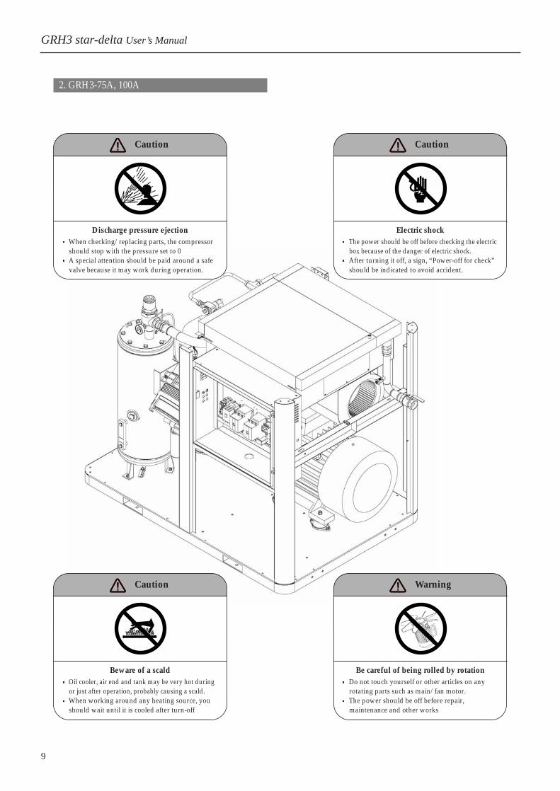
2. GRH3-75A, 100A
GRH3 star-delta User’s Manual
Caution
Electric shock The power should be off before checking the electricbox because of the danger of electric shock. After turning it off, a sign, “Power-off for check”should be indicated to avoid accident.
Caution
Discharge pressure ejection When checking/replacing parts, the compressorshould stop with the pressure set to 0 A special attention should be paid around a safevalve because it may work during operation.
Warning
Be careful of being rolled by rotation Do not touch yourself or other articles on anyrotating parts such as main/fan motor. The power should be off before repair,maintenance and other works
Caution
Beware of a scald Oil cooler, air end and tank may be very hot duringor just after operation, probably causing a scald. When working around any heating source, youshould wait until it is cooled after turn-off

1. About Safety
10 / Hanshin
Warning
Be careful of being rolled by rotation Do not touch yourself or other articles on anyrotating parts such as main/fan motor. The power should be off before repair,maintenance and other works
Caution
Beware of a scald Oil cooler, air end and tank may be very hot duringor just after operation, probably causing a scald. When working around any heating source, youshould wait until it is cooled after turn-off
Caution
Cautious of InhalationPoorly-ventilated indoor operation may cause deathor accident. Do not directly inhale the compressed air nor useit for air supply of the respiratory organs.
11
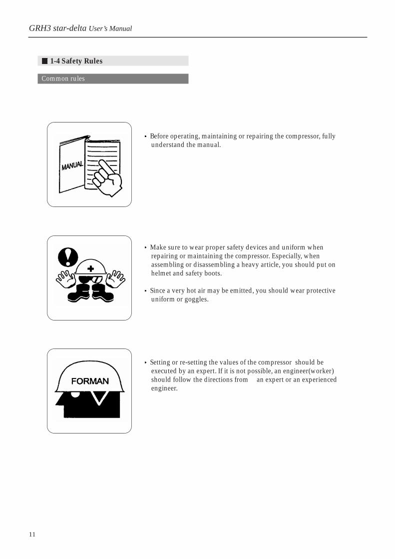
1-4 Safety Rules
Common rules
Before operating, maintaining or repairing the compressor, fullyunderstand the manual.
Make sure to wear proper safety devices and uniform whenrepairing or maintaining the compressor. Especially, whenassembling or disassembling a heavy article, you should put onhelmet and safety boots.
Since a very hot air may be emitted, you should wear protectiveuniform or goggles.
Setting or re-setting the values of the compressor should beexecuted by an expert. If it is not possible, an engineer(worker)should follow the directions from an expert or an experiencedengineer.
GRH3 star-delta User’s Manual
12 / Hanshin
1. About Safety
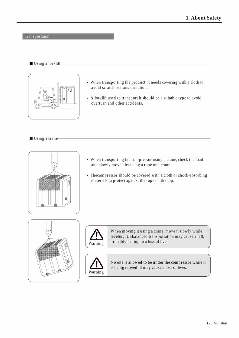
Transportaion
Using a forklift
Using a crane
When transporting the product, it needs covering with a cloth toavoid scratch or transformation.
A forklift used to transport it should be a suitable type to avoidoverturn and other accidents.
When transporting the compressor using a crane, check the loadand slowly moveit by using a rope or a crane.
Thecompressor should be covered with a cloth or shock-absorbingmaterials to protect against the rope on the top.
When moving it using a crane, move it slowly whileleveling. Unbalanced transportation may cause a fall,probablyleading to a loss of lives. Warning
No one is allowed to be under the compressor while itis being moved. It may cause a loss of lives.
Warning

13
1-5 Installation Place and Cautions for Installation
Place
The compressor is designed to use indoors. Please avoid installing it outside.
Installation
GRH3 star-delta User’s Manual
Air-tight space
Installing in a place directly exposed to raindrops orunderground with hot ambient temperature maycause electric shock, drain or rust. Caution
Installing the compressor in a place with vibrationmay cause bad contact, destruction of air end andpiping, so a measure should be taken before theinstallationCaution
If the compressor is installed in a place with harmfulgas, it may cause oxidization of lubricant andcorrosion parts.Caution
Do not leave any flammable materials around thecompressor. Any work causing a fire is alsoprohibited. Once a flame is moved into thecompressor, it may cause damages.Caution
Do not install the compressor in a place with 40°…andhigher ambient temperature. It may cause a fire ordamages on the compressor.Caution
When installing it in an airtight space, it needsinduction and ventilation pipes. And the vent needs afan to ventilate the space.Caution

14 / Hanshin
1. About Safety
Wiring should be executed in accordance with the indoor wiringrules of the common industrial technology standard, electric facilitystandards.Wiring should be executed only by a competent electrician. When wiring on the terminals of the compressor, it should be wiredto avoid any bending part while a hole into which wires arepenetrated should be protected for the sheath from vibration byusing rubber and other materials.
Install a circuit breaker suitable for the type on the power lead-in.
Connect the grounding to the grounding terminal inside the electric box.
The grounding should be type 3 grounding if the voltage is lower thanAC400V or special type 3 grounding if the voltage is AC400V and higher.
1-6 Cautions for Electric Wiring
Wiring
Circuit Breaker
Protective Devices
Grounding
Since electric leakage, weak insulation, overcurrent, ground fault,open-phase operation or defect of protective devices may cause afire on electric circuits, it should be wired in accordance with theindoor wiring rules and periodically maintained.Caution
Removing and improving the compressor protective devices orchanging the settings may cause an accident. Never attempt tochange or alter the settings of protective devices.Caution
Without grounding, it may cause an electric shock accident orfailure of the compressor.
Caution

15
1-7 Cautions for Operation
GRH3 star-delta User’s Manual
If a trouble occurs, immediately stop the operation toavoid any physical injuries or damages on thecompressor. In an emergency, promptly pressEmergency Stop button to stop it.Caution
The compressor’s discharge pressure is very high.Never inject it toward a person.
Caution
To avoid any electric shock, the power should be offbefore repairing or maintaining the compressor.
Caution
Do not leave any flammable materials around thecompressor. Never attempt a work probably causing afire.Caution
Do not inhale the compressed air from the compressornor use it as the air supply for the respiratory organs.
Caution
Do not try welding or any similar works around thecompressor. Flames may cause a fire.
Caution
16 / Hanshin
1. About Safety
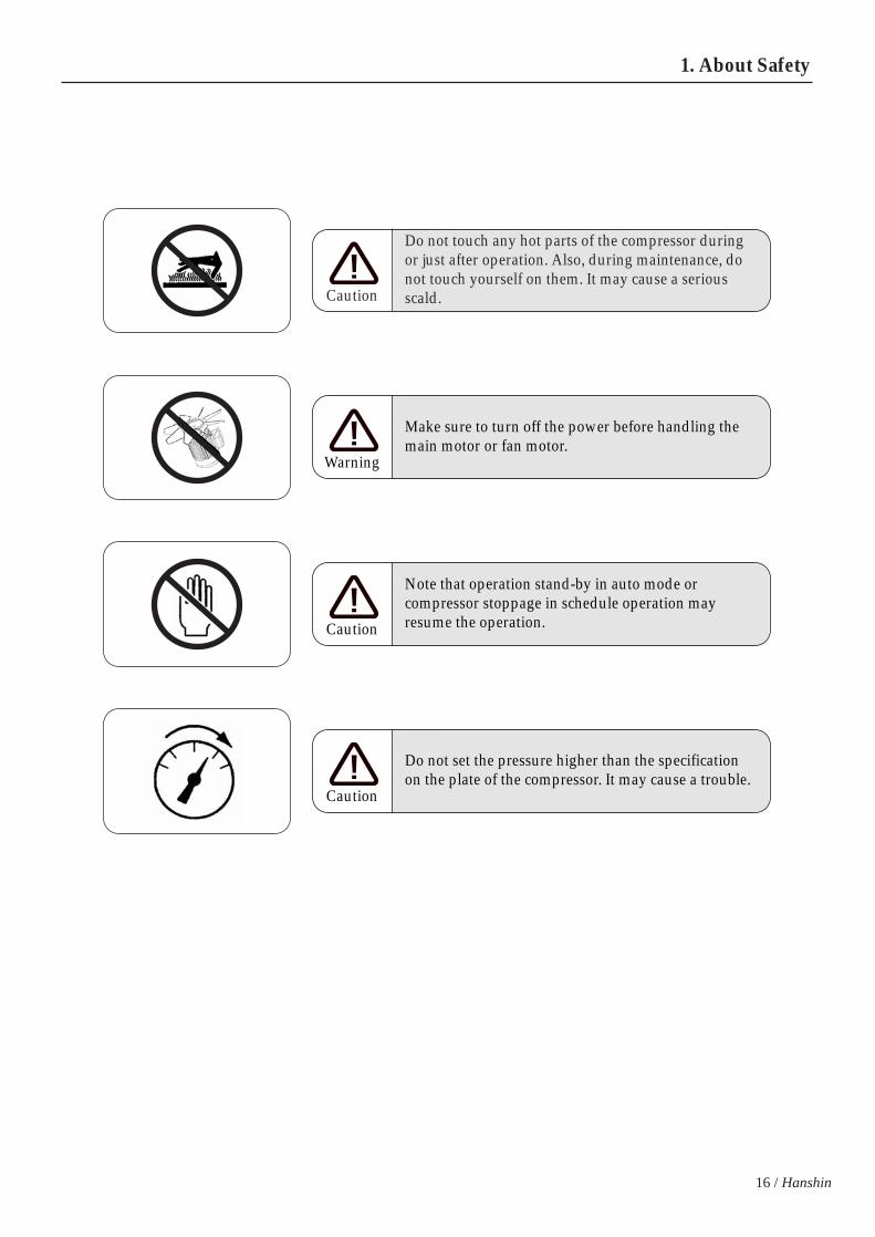
Do not touch any hot parts of the compressor duringor just after operation. Also, during maintenance, donot touch yourself on them. It may cause a seriousscald.Caution
Make sure to turn off the power before handling themain motor or fan motor.
Warning
Note that operation stand-by in auto mode orcompressor stoppage in schedule operation mayresume the operation.Caution
Do not set the pressure higher than the specificationon the plate of the compressor. It may cause a trouble.
Caution

17
GRH3 star-delta User’s Manual
1-8 Cautions for Stoppage
Parallel Operation
Once the compressor stops, close the ball andvalve of the discharge pipes to avoid anybackward flowing of water and other materials.
1-9 Cautions for Maintenance
Pressure
Power
Power
Keep the operation log.Make sure to use the genuine parts only. Thecompressor may not work nor cause a troubleunless the genuine parts are used.
Stoppage for a long while
Turn off the main power when the compressoris not used for period of long time.Operate it once a week for, at least, 30 minutesto avoid rust inside pipes of the compressor.
Routine Maintenance
Routinely check the compressor. For the checklist, refer to the contents specifiedin page 63
Valve closed
Operation
Stoppage
Stop the compressor and check whether the pressureis set to “0” bar and whether any remaining pressureinside pipes exists.Caution
When replenishing oil or checking the electric box,make sure to turn it off first.
Caution

18 / Hanshin
1. About Safety 2. Names of Parts
Front side
Rear side
2. Names of Parts
upper cover
Micom
oil gauge window
front-left door
front-right door
compressed air discharge outlet
rears-side door
air inlet
vent duct connector
right-side door(R)
right-side door(L)
power cable lead-in opening
left-side door(R)
left-side door(L)
2-1 GRH3-20A, 25A, 30A, 35A, 50A
Fully understand the names and functions of parts relating to the routine operation and manage the compressor.
1. Appearance

19
cooling fan
control panel
power cableconnection
oil inlet
oil gauge
oil discharge valve
vent duct
compressed airdischarge outlet
main motor
motor base
discharge pipe
Oil/After cooler
discharge pressureconnection
motor pully
pully belt
inhalation valve
aie end pully
holding pressurevalve
safety valve
internalpuressure switch
separator tank
thermostat valve
oil filter
air end
inhanlation valve
2. Inside
GRH3 star-delta User’s Manual
internal pressuregauge

20 / Hanshin
2. Names of Parts
Front side
Rear side
upper cover
front-right door
front-left door
oil gauge window
Micom
front-right door
rears-left door
rears-right door
vent duct connector
right-side door
right-side door
air inlet
power cablelead-in opening
left-side door
air inlet
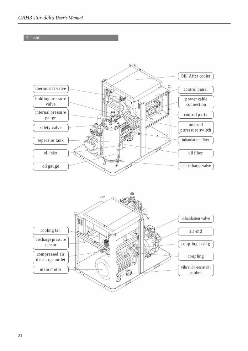
2-2 GRH3-75A, 100A
Fully understand the names and functions of parts relating to the routine operation and manage the compressor.
1. Appearance
compressed air discharge outlet
21
thermostat valve
safety valve
separator tank
oil inlet
oil gauge
cooling fan
main motor
Oil/After cooler
control panel
control parts
inhanlation filter
oil filter
oil discharge valve
inhanlation valve
air end
coupling casing
coupling
vibration-resistantrubber
2. Inside
GRH3 star-delta User’s Manual
power cableconnection
compressed airdischarge outlet
discharge pressuresensor
holding pressurevalve
internal pressuregauge
internalpuressure switch

22 / Hanshin
2. Names of Parts 3. Electic Wiring
3. Electic Wiring
3-1 Wiring
1. Wiring
The compressor is already wired internally. Ifopening the front door, you may find a hole forlead-in power cable on the bottom of the right side.Insert a wire into the hole for connection.
If opening the front door, there is TB1. Pleaseconnect the power to it.
In case of wiring to the electric box, use rubberbushing to protect the cable sheath and wire it toavoid removal of the sheath.
Cable lead-inhole
TB1Powerconnectionterminal
Groundingterminal spec.for the lead-in : M8
2. Electric cable specifications.
Use the EV or CV cable for 600V. For the thickness,refer to page 24.
3. Grounding
Ground in accordance with the KSC Rules. Thegrounding terminal inside the compressor’s electricbox is located as presented in the below figure.
Main motor cap.15(kW)18(kW)22(kW)27(kW)37(kW)55(kW)75(kW)110(kW)150(kW)
AC220V48A58A71A87A119A178A242A356A486A
AC380V28A33A41A50A69A103A140A206A281A
AC440V24A29A35A43A60A89A121A178A243A
Rated current of main motor
* The rated current may vary depending on a motor type.
The lead-in cabling to the compressor should be executed by an competentengineer. Any poor wiring may cause electic shock or other electric fault.Do not alter control parts or electric circuits attached to the electric box. Thecompressor may be damaged due to malfunction of protection.When opening the electric box door for routine maintenance or repairs, the mainpower should be turned off to avoid any electric shock accident.
Caution

2 4 3 1
23
4. Installation of circuit breaker for wiring
Attach a circuit breaker for wiring on the primarypower supply of the compressor. For the capacity of the breaker, refer to page 24.
When repairing or maintaining the compressor,make sure to turn if off first.
Example of circuit-breaker wiring.
5. Routine checkpoints
If any impurities or dust is found inside whenvisually inspecting it, turn it off and clean it upwith compressed air.
Black cable is power cable and the red/white/blueinsulation tubes are inserted at the end of it. If thecolors of insulation tubes are discolored to black,check the tightness of screws. If screws are loosely tightened, it may generateheat, deteriorating cables and probably leading to afire, so they should be maintained once a month.
Cable checkpoints
6. Check motor insulation resistance
Take the following steps if insulation resistance isto be checked, for instance, operation of circuit-breaker.
1) Turn off the power of the compressor.2) Set the voltage range of insulation resistance
tester lower than 500V. 3) How to check the resistance;
Loosen the bolt with (motor’s cable) andseparate the cable from the terminal.
If it displays 10M and over as the above, it isnormal.
Lead-in power
Circuit-breaker
Connecting to TBI of the compressor’selectric box.
1
4
3
2
4
Main terminal(TB1) Fan motor magnet
Main motor magnet Operation magnet
Connecting to motor cable R(S,T)
Connecting to the grounding terminal
Insulationresistance tester
GRH3 star-delta User’s Manual

24 / Hanshin
3. Electic Wiring
3-2 Power Facilities
1. Cable thickness
Since the compressor may not work properly dependingon the power facility capacity and the thickness/lengthof the power cable and it may stop due to voltagedropping of control circuit or defective acceleration of themain motor, make sure to supply the power with thevoltage dropping set within 5% of the rated power.
For the cable thickness of the lead-in cable, refer to thefollowing table.
It is recommended that the cable length between atransformer/distribution board and the compressor is 100m andshorter; if longer than the length, the thickness may need reselecting.
2. Grounding Spec.
Grounding specifications are as follows.
3. Thickness of grounding cable
Cable thickness(mm2)
AC220
AC440
15(18)
14
8
22(27)
22
14
37
60
38
Main motor cap.(kW)
4. Circuit breaker capacity
The main power supply essentially needs a circuitbreaker to avoid electric shock and protect the motor.
When selecting a breaker, refer to the following table.
The above capacity used to select a breaker isavailable for Inverter and Y-D operating models.
Main motorcapacity(kW)
15
18
22
27
37
55
75
110
150
180
Supply power spec.
AC220V
AC440V
AC220V
AC440V
AC220V
AC440V
AC220V
AC440V
AC220V
AC440V
AC220V
AC440V
AC220V
AC440V
AC220V
AC440V
AC220V
AC440V
AC220V
AC440V
Circuit breaker cap.
ABS103-75
ABS53-50
ABS103-100
ABS53-50
ABS103-100
ABS103-60
ABS103-100
ABS103-75
ABS203-200
ABS103-100
ABS203-225
ABS203-150
ABS403-350
ABS203-200
ABS403-400
ABS403-250
ABS603-600
ABS403-350
ABS803-700
ABS403-400
55
100
60
75
125
60
110
200
150
150
250
200
180
325
250
Voltage
AC220V
AC440V
Grounding typeType 3
Special type 3
Grounding resistance
100 and lower
10 and lower
Rated current
20A and lower
30A and lower
50A and lower
100A and lower
150A and lower
200A and lower
400A and lower
600A and lower
Cable thickness (mm2)
2.0 and thicker
2.0 and thicker
3.5 and thicker
5.5 and thicker
8.0 and thicker
14 and thicker
22 and thicker
38 and thicker
Make sure to install a circuit-breaker on the power. Please ground the compressor to avoid any damages on the main motor orelectric shock accident.
Caution

25
Model
Total weight(kg)
GRH3-20A
673
GRH3-25A
700
GRH3-30A
726
GRH3-35A
753
GRH3-50A
940
GRH3-75A
1596
GRH3-100A
1713
4. Installation and Piping
4-1 Identification of the product specifications
When accepting and unpacking the compressor, please check the specifications such as pressure, voltage andfrequency by using the plate attached on the left side.
Check whether there is any damage/scratch or transformation on covers during the transportation.
4-2 Cautions for Transportation
Weights of compressor models
Completely load it so that thefork comes out
Using a scratch-protective cloth
Using a wire withproper strength
Using a strut toprotect covers
GRH3 star-delta User’s Manual
Using a forklift Using a crane
Using shock-absorbing materials toprotect the frame and rope
Use a plate to avoid any scratch.
NOTE> GRH3-75W : 1383kg / GRH3-100W : 1500kg
26 / Hanshin
4. Installation and Piping
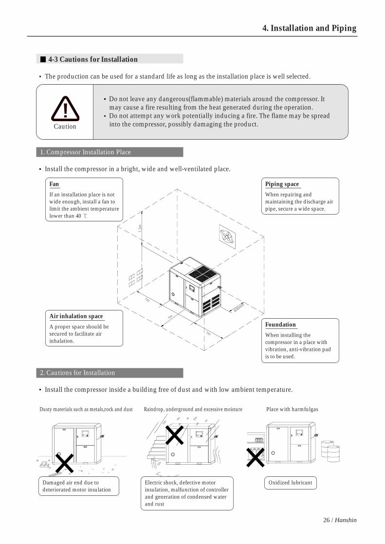
4-3 Cautions for Installation
The production can be used for a standard life as long as the installation place is well selected.
1. Compressor Installation Place
Install the compressor in a bright, wide and well-ventilated place.
Fan
If an installation place is notwide enough, install a fan tolimit the ambient temperaturelower than 40
Piping space
When repairing andmaintaining the discharge airpipe, secure a wide space.
Air inhalation space
A proper space should besecured to facilitate airinhalation.
Foundation
When installing thecompressor in a place withvibration, anti-vibration padis to be used.
Do not leave any dangerous(flammable) materials around the compressor. Itmay cause a fire resulting from the heat generated during the operation.Do not attempt any work potentially inducing a fire. The flame may be spreadinto the compressor, possibly damaging the product.Caution
2. Cautions for Installation
Install the compressor inside a building free of dust and with low ambient temperature.
Damaged air end due todeteriorated motor insulation
Electric shock, defective motorinsulation, malfunction of controllerand generation of condensed waterand rust
Oxidized lubricant
Dusty materials such as metals,rock and dust Raindrop, underground and excessive moisture Place with harmfulgas
27
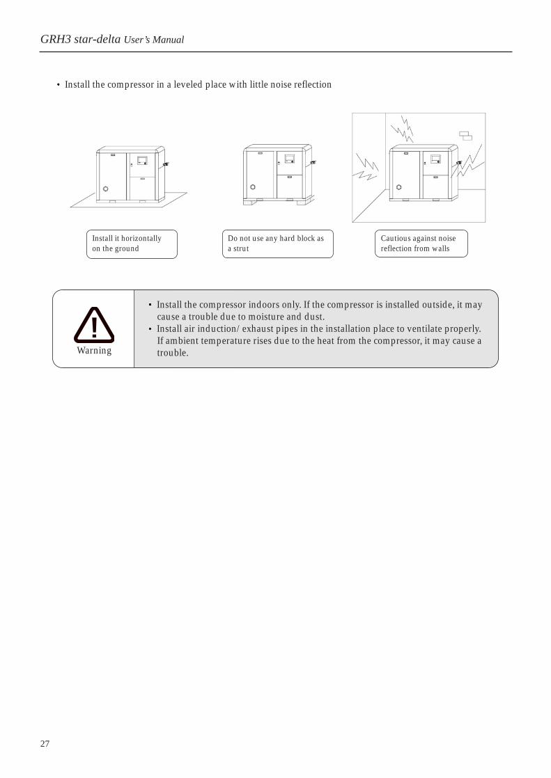
Install the compressor in a leveled place with little noise reflection
Install it horizontallyon the ground
Do not use any hard block asa strut
Cautious against noisereflection from walls
Install the compressor indoors only. If the compressor is installed outside, it maycause a trouble due to moisture and dust. Install air induction/exhaust pipes in the installation place to ventilate properly.If ambient temperature rises due to the heat from the compressor, it may cause atrouble.Warning
GRH3 star-delta User’s Manual

28 / Hanshin
4. Installation and Piping
3. Ventilation of compressor’s room
Air InletPrepare an air inlet larger than 1m2 perset at a lower place. The air inlet shouldbe protected against dust.
Vent openingVent opening is to be installed on the topof a building so that hot air is ventilatedto the outside.
Vent ductWhen installing a vent duct, make sureto connect it to the compressor cooler’supper vent.
When installing a vent duct on thecompressor, install it in a structure toeasily repair and maintain.
Vent duct
Air inlet
CompressorModel
Ventilation vol.(m3/min)
GRH3-20A
105
GRH3-25A
105
GRH3-30A
105
GRH3-35A
105
GRH3-50A
150
GRH3-75A
300
GRH3-100A
300
Ventilation data <If vent duct is not installed>
If the temperature of the compressor’s room is higher than the allowabletemperature range, install a forced ventilation facility to ventilate promptly.Operating the compressor at 40 and higher for a long time may cause a fatalfault. Warning
29
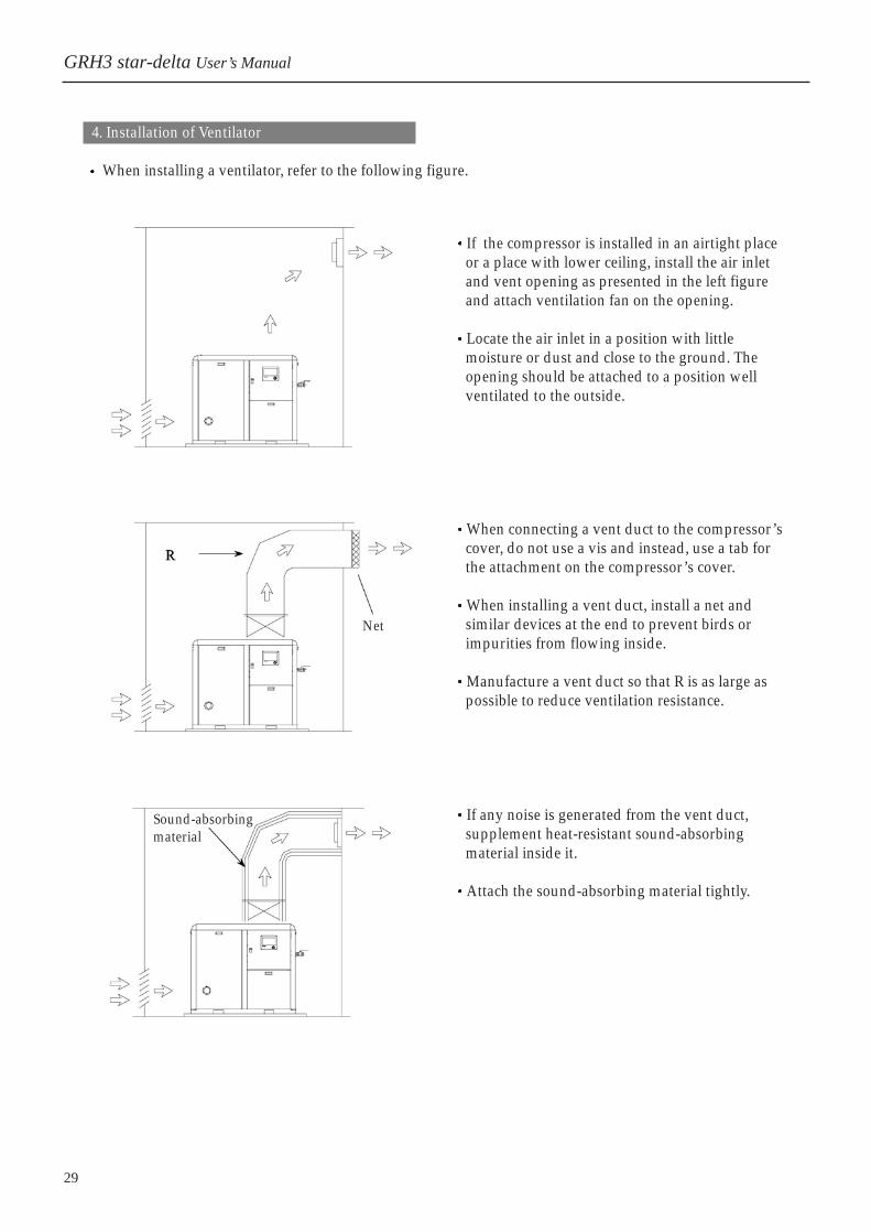
4. Installation of Ventilator
When installing a ventilator, refer to the following figure.
If the compressor is installed in an airtight placeor a place with lower ceiling, install the air inletand vent opening as presented in the left figureand attach ventilation fan on the opening.
Locate the air inlet in a position with littlemoisture or dust and close to the ground. Theopening should be attached to a position wellventilated to the outside.
When connecting a vent duct to the compressor’scover, do not use a vis and instead, use a tab forthe attachment on the compressor’s cover.
When installing a vent duct, install a net andsimilar devices at the end to prevent birds orimpurities from flowing inside.
Manufacture a vent duct so that R is as large aspossible to reduce ventilation resistance.
If any noise is generated from the vent duct,supplement heat-resistant sound-absorbingmaterial inside it.
Attach the sound-absorbing material tightly.
Net
Sound-absorbingmaterial
GRH3 star-delta User’s Manual
30 / Hanshin
4. Installation and Piping
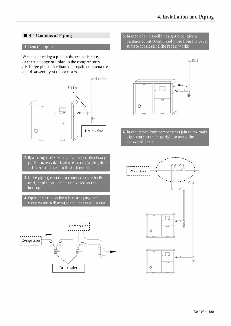
4-4 Cautions of Piping
1. General piping
When connecting a pipe to the main air pipe,connect a flange or union to the compressor’sdischarge pipe to facilitate the repair, maintenanceand disassembly of the compressor
5. In case of a vertically upright pipe, give adistance about 600mm and more from the coversurface considering the repair works
6. In case pipes from compressors join to the mainpipe, connect them upright to avoid thebackward drain.
Union
Drain valve
Drain valve
Compressor
Compressor
Main pipe
2. By attaching a ball, valve or similar device on the dischargepipeline, make a valve closed when it stops for a long timeand prevent moisture from flowing backward
3. If the piping contains a concave or verticallyupright pipe, attach a drain valve on thebottom.
4. Open the drain valve when stopping thecompressor to discharge the condensed water.

31
7. Cautions for parallel piping
8. Cautions for parallel piping
Completely, close the stop valve of the dischargevalve at the compressor that is manually stoppedduring the operation.
If opening the stop valve of the suspendedcompressor, the backward pressure is allowed toAfter Cooler at the compressor, generating adrain, probably causing rust inside the cooler andcheck valve and subsequently, reducing the life ofthe compressor.
Operating
Stopping
Stop valve opened
Stop valve closed
Stop valve
Stop valve
Apply shock-absorbing materials to the reciprocating compressor so that thevibration of reciprocating compressor is not conveyed to the screw compressor,probably generating air leakage.
Warning
GRH3 star-delta User’s Manual
32 / Hanshin
4. Installation and Piping
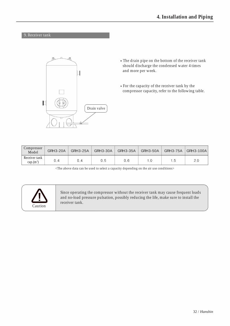
9. Receiver tank
The drain pipe on the bottom of the receiver tankshould discharge the condensed water 4 timesand more per week.
For the capacity of the receiver tank by thecompressor capacity, refer to the following table.
Drain valve
<The above data can be used to select a capacity depending on the air use conditions>
CompressorModel
Receiver tank cap.(m3)
GRH3-20A GRH3-25A GRH3-30A GRH3-35A GRH3-50A GRH3-75A GRH3-100A
Since operating the compressor without the receiver tank may cause frequent loadsand no-load pressure pulsation, possibly reducing the life, make sure to install thereceiver tank.
Caution

33
5. Operations
5-1 Micom Controller
1. Micom Controller consists of LCD display, LED lamps, push button switches and data setting button.
Graphic DisplayThe operation is graphically displayed.The brightness is automatically adjusted, depending on the ambient temperature.The bright and clear display facilitates repairs in a dark place.If a trip occurs, it shows the location and detail troubleshooting.
Start button/lampTo start operation, press [START] button.
Stop button/lampThe compressor stops after 10-second noload operation if pressing [STOP button]
Schedule Operation button/lampIf pressing [SCH MODE] button, theschedule operation mode is selected. Ifpressing [START] button after selecting[SCHMODE], it operates in accordancewith the setting.
Operation data setting/change buttons Data can be set and changed for optimal operation under any environment bychanging the operation data.
Load indication lamp No load operation buttonThe compressor can be easily maintained and checked because green lamp is on incase of load operation and it starts no-load operation if pressing the button.
Alarm lampIf any alert occurs, the yellow lamp is on and it calculates a parts replacement timeautomatically, turning on the lamp
Trip lampIf the compressor stops due to a trip, the red lamp is on.
GRH3 star-delta User’s Manual

CN2 CN5 CN6 CN3 CN4 CN1
Fuse 250V /5A Micom PCB
Front
Detail
Wiring diagram of pressure and temperature sensor
No.123
Cable ColorRed
WhiteWhite
Signal NameAbb
No.1234
Cable ColorRed
BlackWhite
Shield Cable
Signal Name+24
GNDSIGNAL
E
34 / Hanshin
5. Operations
2. Rear view of the Micom Controller
3. ACP-2007(Analogue controller)
GRH3-20A, 25A, 30A and 35A models basically contain an analogue controller.For the functions and operation, refer to the follows.
Displaying air supplypressure
Operation mode selection switch[AUTO] Auto Operation Mode[CONT] Continuous Operation Mode
Operation button/Operation lampIf pressing [START] button, thecompressor operates
Stop button/Stop lampIf pressing [START] button,the compressor operates
In [Auto] mode, the compressorstops after no-load operation for apre-defined time and automaticallyrestarts if the pressure falls fewerthan the value.
Total operation hours indicatorDisplaying the compressor’s total operation hours
Fan Motor Overload LampDisplaying fan motor overload
Main Motor Overload LampDisplaying the main motor’s overload
High discharge temperature alarm lampThe lamp is on and the compressor stops in case of high temperature
Load operation indication lampThe lamp is on when it 55operates under load
Auto stop indication lampThe lamp is on when itautomatically stops.
CN5Temp. sensor connector
CN3Pressure sensor connector
CN6(Lubricant oil temperature)
Oil sensor connectorCN1Control signal of magnet/sol valves
35
5-2 Operation Control
1. Turn on
If it is turned on with the MCB on inside thecontrol box, the controller’s main LCD is activated.Micom is self-checked and is readily stand-by foroperation.
If any fault is found in a compressor after turningon Micom, it displays alarm and trip; or, it showsthe above display.
2. Operation Stop
To start the operation, press[START] button. Then, [START]lamp is on in red.
To stop the operation, press[STOP] button. Then, [STOP] lampis on in green.
For schedule operation, press[SCHEDULE] button once to selectthe schedule mode. To cancel it, press the button oncemore.
If pressing [START] button afterselecting the schedule mode, acompressor operates and stops inaccordance with the pre-definedschedule operation time. To suspend it during operation,press [STOP] button.
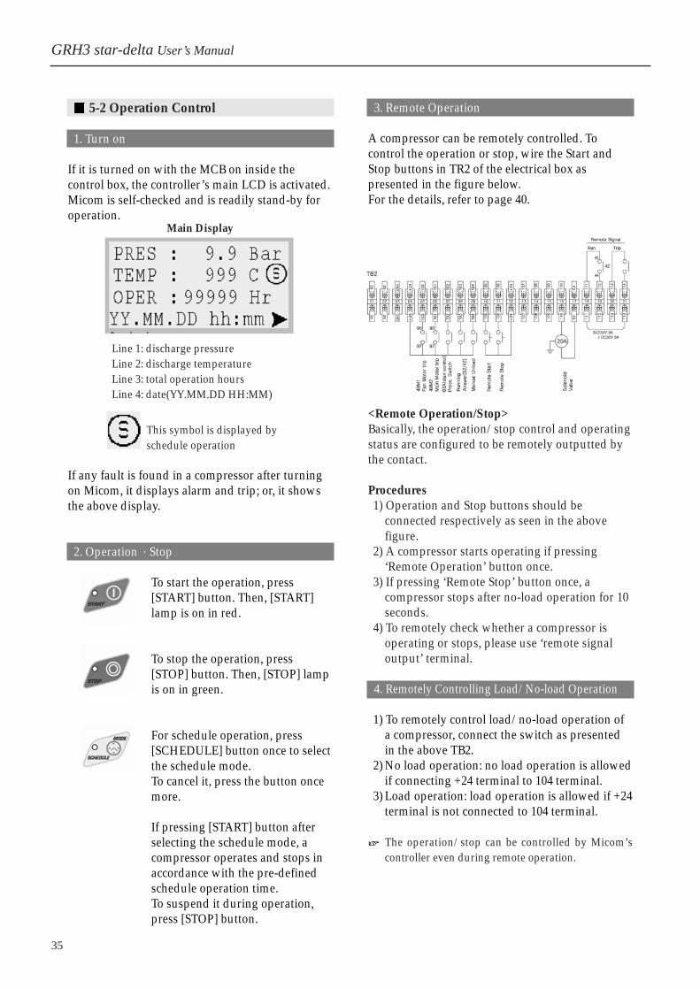
3. Remote Operation
A compressor can be remotely controlled. Tocontrol the operation or stop, wire the Start andStop buttons in TR2 of the electrical box aspresented in the figure below. For the details, refer to page 40.
<Remote Operation/Stop>Basically, the operation/stop control and operatingstatus are configured to be remotely outputted bythe contact.
Procedures1) Operation and Stop buttons should be
connected respectively as seen in the abovefigure.
2) A compressor starts operating if pressing‘Remote Operation’ button once.
3) If pressing ‘Remote Stop’ button once, acompressor stops after no-load operation for 10seconds.
4) To remotely check whether a compressor isoperating or stops, please use ‘remote signaloutput’ terminal.
4. Remotely Controlling Load/No-load Operation
1) To remotely control load/no-load operation ofa compressor, connect the switch as presentedin the above TB2.
2) No load operation: no load operation is allowedif connecting +24 terminal to 104 terminal.
3) Load operation: load operation is allowed if +24terminal is not connected to 104 terminal.
The operation/stop can be controlled by Micom’scontroller even during remote operation.
Main Display
Line 1: discharge pressure Line 2: discharge temperature Line 3: total operation hoursLine 4: date(YY.MM.DD HH:MM)
This symbol is displayed byschedule operation
GRH3 star-delta User’s Manual
36 / Hanshin
5. Operations
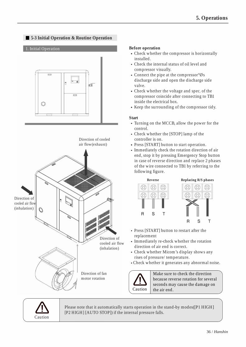
5-3 Initial Operation & Routine Operation
1. Initial Operation Before operationCheck whether the compressor is horizontallyinstalled.Check the internal status of oil level andcompressor visually. Connect the pipe at the compressor°Øsdischarge side and open the discharge sidevalve. Check whether the voltage and spec. of thecompressor coincide after connecting to TB1inside the electrical box. Keep the surrounding of the compressor tidy.
StartTurning on the MCCB, allow the power for thecontrol. Check whether the [STOP] lamp of thecontroller is on. Press [START] button to start operation. Immediately check the rotation direction of airend, stop it by pressing Emergency Stop buttonin case of reverse direction and replace 2 phasesof the wire connected to TB1 by referring to thefollowing figure.
Press [START] button to restart after thereplacement Immediately re-check whether the rotationdirection of air end is correct.Check whether Micom’s display shows anyrises of pressure/temperature.
Check whether it generates any abnormal noise.
Direction of cooledair flow(exhaust)
Direction ofcooled air flow(inhalation)
Direction ofcooled air flow(inhalation)
Direction of fanmotor rotation
Reverse Replacing R/S phases
Please note that it automatically starts operation in the stand-by modes([P1 HIGH][P2 HIGH] [AUTO STOP]) if the internal pressure falls.
Caution
Make sure to check the directionbecause reverse rotation for severalseconds may cause the damage onthe air end.Caution
37
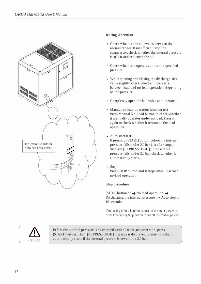
During Operation
Check whether the oil level is between thenormal ranges. If insufficient, stop thecompressor, check whether the internal pressureis ‘0’ bar and replenish the oil.
Check whether it operates under the specifiedpressure.
While opening and closing the discharge-sidevalve slightly, check whether it convertsbetween load and no-load operation, dependingon the pressure.
Completely open the ball valve and operate it.
Manual no-load operation function testPress Manual No-Load button to check whetherit manually operates under no load. Press itagain to check whether it returns to the loadoperation.
Auto start testIf pressing [START] button before the internalpressure falls under 2.0 bar just after stop, itdisplays [P1 PRESS HIGH]; if the internalpressure falls under 2.0 bar, check whether itautomatically starts.
StopPress STOP button and it stops after 10-secondno-load operation.
Stop procedure
[STOP] button on No load operation Discharging the internal pressure Auto stop in10 seconds.
If not using it for a long time, turn off the main power orpress Emergency Stop button to cut off the control power
Indication should bebetween both limits.
GRH3 star-delta User’s Manual
Before the internal pressure is discharged under 2.0 bar just after stop, press[START] button. Then, [P1 PRESS HIGH] message is displayed. Please note that itautomatically starts if the internal pressure is lower than 2.0 bar.Caution

38 / Hanshin
5. Operations
2. Routine Operation
Opening the front cover, check whether thecompressor has any impurities or oil leakage.Then, open the electrical box door and visuallyinspect the tightness of power cable(black).Since the power cable is loosely connected,discoloring the red/white/blue color tubes,turn it off and re-check the cable.
OperationPress [START] button to start it.
During operation, check the oil level. Ifinsufficient, stop the operation and replenish theoil.
StopIf pressing [STOP] button, it stopsafter 10 second no-load operation.If pressing it again when it stops by[STOP] button, it immediately stops.
If the P2 pressure is not formed 2.0 bar andhigher in 10 minutes of the operation, itgenerates [P-SENSOR TROUBLE] and stops, socheck the inhalation valve opening, slightlyclose P2 side ball valve and operate it.
If the P2 side pressure is completely discharge tothe air during the operation, the pressure is ‘0’ bar,so at the moment, [P-SENSOR TROUBLE] messageis displayed.
When it stops for a long time, close thedischarge side ball valve to prevent any reverseflow. In addition, press Emergency Stop buttonor turn off the main power, avoiding any safetyaccident.
When changing the operation conditions suchas operation pressure, refer to page 49.
The initial values of operation pressure are asfollows.
<Compressor’s pressure spec.: 7.0bar>
When the above pressure is set, It operates under no-load if it is higher than 7.0baror under load if it is 6.0 bar and lower(AR03 -AR02).
When changing operation pressure, otheroperation data will be automatically changed forthe optimal operation.
<NOTE>
How to reset: press [STOP] button. If any trouble occurs during operation, it immediatelystops. Then, check trouble causes, take a correctivemeasure and press [STOP] button to release the trouble.
ItemDiff. pressure
Operation pressureAuto restart pressureY-D switchover timeAuto stop time
CodeAR02AR03AR05T01T02
Initial value1.0bar7.0bar1.0bar5.0Sec
10 minutes
<NOTE>
P1: internal pressure of the compressorP2: end pressure of the compressor

39
5-4 Schedule Operation
1. Check and enter the schedule operation time.
For the directions, refer to page 49.
2. If selecting Schedule mode by pressing Schedule operation mode button once, the following screen isdisplayed.
3. If pressing START button, it shows the following screen and the compressor operates and stops inaccordance with the schedule operation time.
Displaying thepressuredetected
Displayingstart presure
Schedule operation stand-by screenDuring schedule operation: the screen is displayedwhen the compressor is stand-by before theschedule operation time
Schedule operation screenDuring schedule operation: if the compressoroperates at the time of schedule operation, the leftscreen is displayed.When the main motor rotates by schedule
operation, mark blinks.
GRH3 star-delta User’s Manual

40 / Hanshin
5. Operations
5-5 Remote Operation
It is basically structured so that the remote operation, stop control and operation status are outputted to thecontact. Just attach the Start and Stop buttons as presented in the below figure.
1. Remote Operation
It operates if turning on No.10 terminal(105) andNo.12 terminal(+24) once.
2. Remote Stop
It stops if turning on No.11 terminal(106) andNo.12 terminal(+24) once.
3. On contact during operation
During operation, No.18 terminal(111) and No.19terminal(112) are on.
4. On contact if any abnormal status
If any trouble occurs, No.20 terminal(113) andNo.21 terminal(114) are on.
5. Remote manual no-load instruction terminal
If No.04 terminal(+24) and No.09 terminal(104) areon, it operates under no load and when they areoff, its pressure is automatically controlled.

41
5-6 Remote Monitoring System [Micom]
When it is necessary to remotely monitor compressor operation, stop and operation status, using [RemoteMonitoring Control System] may facilitate the management of the compressor. It is structured as follows.
<Specifications>Dimensions: 320(W) x 270(H) x 120(D)Power Supply: AC220V Single Phase 50VAConnection Control Cable: UTP Lan Cable 1 cable
Every situation displayed on the compressor Micom such as compressor operation temperature, dischargepressure, filter use time and troubles is displayed on the remote monitoring system(remote controller).
i.e.) Operation status display screenRemote Controller
AC220V power supply
UTP(LAN) cable 1 line connection
UTPcable connecitonposition within Micom
Compressor
COM connect
GRH3 star-delta User’s Manual

42 / Hanshin
5. Operations
5-7 Remote monitoring System [Computer]
When remotely monitoring compressor operation, stop control and operation status, using [RemoteMonitoring Control System] may facilitate the control of the compressor, it is structured as follows.
Components: computer, COM card[computer], COM cableNo. of controlled sets: 8
Computer monitor
Every computer connected on LAN
HUB Internet
Every computerconnected to Internet
No. 1 No. 2 No. 3 No. 4

43
5-8 Micom Display Configuration & Operations
1. Display Configuration
Micom display consists of 4 screens; main operation screen, auxiliary operation screen, operation status screenand data setup screen.
2. Screen Operation flow
It displays operation frequency, no loadfrequency, filter and operation time.
It is displayed if the compressorturns on and operates normally.
The screen depending onoperation status is displayed.
The screen is used to check operationdata setup and the values.
Main Operation Screen
Operation Status Screen
Data Setup Screen
Auxiliary Operation Screen
Press [ ] button to convertPress [ ] button to convert.It is automatically converted by operation statusIt is automatically converted if releasing, if any. a tripIt is converted by pressing [ ] and [ENT].It is converted if pressing [ESC] and [ ].
GRH3 star-delta User’s Manual

44 / Hanshin
5. Operations
5-9 Operation Data Setup and Check
1. Operation Display
[Main Screen]Display discharge pressure / discharge temp. /total operation timeTo go to the auxiliary operation screen, press [ ] button.
PRES : 9.9 - operation pressure displayTEMP : 999 - discharge temperature displayOPER : compressor’s total operation hours
[Auxiliary Screen]Display the motor start frequency and load/no-loadoperation conversion frequency. To go to the main screen, press [ ] button.
S : 9999 - Motor start frequency L : 9999 - Load/no-load conversion frequencyAir F. - Air filter use timeOil F. - Oil filter use timeOil S. - Oil separator use time
[Fan Motor Trip Display]When the compressor stops due to fan motor fault “pxx” troubleshooting page is displayedRefer to page 52 and control circuit: trip occurs when No.5terminal of TB2, 97-98 is on
Checkpoint : 49M1 settigns, fan motor and etc
[Main Motor Trip Display]When the compressor stops due to main motor fault“pxx”troubleshooting page is displayed Refer to page 52 and control circuit: trip occurs when No.6terminal of TB2, 95-98 is on
Checkpoint : 4EOCR , main motor, air end, pressure setting
[Abnormal Operation Signal , Trip Display]When the compressor stops due to abnormal operation signal“pxx”troubleshooting page is displayed Refer to page 53 and control circuit: trip occurs when No.8terminal of TB2, 13-4 is not on after the start.
Checkpoint : 42 magnet aux. contact point, electrical wiring diagram(drawing)
[Excessive discharge temp., Trip display]When the compressor stops due to excessive discharge temp.“pxx” troubleshooting page is displayedRefer to page 52 and control circuit: trip occurs when thedischarge temperature rises over 110
Checkpoint : oil level, oil cooler, tem. Sensor and etc

45
[Abnormal Temp. sensor, Trip display]When the discharge temperature detection sensor is in trouble“pxx” troubleshooting page is displayedRefer to page 53 and control circuit
Checkpoint : temperature sensor, temperature sensor wiring
[Abnormal pressure sensor, Trip display]When the discharge pressure control sensor is in trouble“pxx” troubleshooting page is displayedRefer to page 53 and control circuit
Checkpoint : pressure sensor, pressure sensor wiring
[Air filter displacement display]When the air filter use time reaches to the replacementlimit(setting)Initial setting : 3000 hrs
Checkpoint : filter replacement and use time resetIf pressing [STOP] button for 10 seconds, [RESET ! OK] message isdisplayed and the use time is reset.
[Oil Filter replacement display]When the oil filter use time reaches to the replacementlimit(setting)Initial setting: 3000 hrs
Checkpoint : filter replacement and use time resetIf pressing [SCHEDULE] button for 10 seconds, [RESET ! OK] message isdisplayed and the use time is reset.
[Oil Separator replacement display]When the oil separator use time reaches to the replacementlimit(setting)Initial setting : 3000 hrs
Checkpoint : filter replacement and use time resetIf pressing [STOP] and SCHEDULE]buttons for 10 seconds, [RESET ! OK]message is displayed and the use time is reset.
[Internal pressure rise auto start stand-by display]If the internal pressure[P1] is 2.0 bar and higher afterpressing [START] button, the auto start stand-by displayappears. If the internal pressure falls under 2.0 bar, it automaticallystarts.
GRH3 star-delta User’s Manual

46 / Hanshin
5. Operations
[Line pressure rise auto start stand-by display]Auto start stand-by display when the compressor’s internalpressure [P2] is higher than the setting after [START ]buttonIt automatically starts when P2 pressure falls under 6.0 bar.
[No load operation display]No-load operation when the pressure rises higher than theno-load start pressure due to reduced air volume. It operatesunder no-load for the set time(10 minutes) and automaticallystops.
[Auto stop display]When the compressor automatically stops under no loadoperationIt automatically starts if the pressure falls under the presetpressure (6.0 Bar).
[Schedule Operation selection display]When pressing schedule operation buttonIf selecting the schedule operation mode and pressingSTART button, it operates and stops according to thepredefined time.
[Stop delay operation display]If pressing STOP button, the compressor stops after 10second no-load operation
Stop delay time count
[Discharge high temp. check alarm display]High temperature check alarm is displayed if the dischargetemperature is between 95 ~110
Notes: if discharge temperature is higher than 110 , a trip attributable toexcessive temperature occurs and the compressor stops.
47
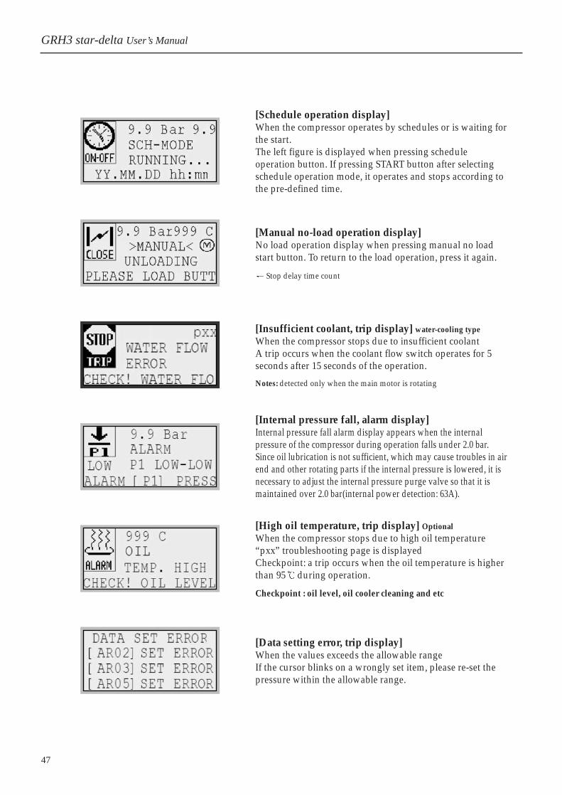
[Schedule operation display]When the compressor operates by schedules or is waiting forthe start. The left figure is displayed when pressing scheduleoperation button. If pressing START button after selectingschedule operation mode, it operates and stops according tothe pre-defined time.
[Manual no-load operation display]No load operation display when pressing manual no loadstart button. To return to the load operation, press it again.
Stop delay time count
[Insufficient coolant, trip display] water-cooling typeWhen the compressor stops due to insufficient coolant A trip occurs when the coolant flow switch operates for 5seconds after 15 seconds of the operation.
Notes: detected only when the main motor is rotating
[Internal pressure fall, alarm display]Internal pressure fall alarm display appears when the internalpressure of the compressor during operation falls under 2.0 bar. Since oil lubrication is not sufficient, which may cause troubles in airend and other rotating parts if the internal pressure is lowered, it isnecessary to adjust the internal pressure purge valve so that it ismaintained over 2.0 bar(internal power detection: 63A).
[High oil temperature, trip display] OptionalWhen the compressor stops due to high oil temperature “pxx” troubleshooting page is displayedCheckpoint: a trip occurs when the oil temperature is higherthan 95 during operation.
Checkpoint : oil level, oil cooler cleaning and etc
[Data setting error, trip display]When the values exceeds the allowable range If the cursor blinks on a wrongly set item, please re-set thepressure within the allowable range.
GRH3 star-delta User’s Manual

48 / Hanshin
5. Operations
2. Operation Data Setup
Operation data setup items
AR01: [ ]AR02: Operation diff. pressureAR03: Operation pressureAR04: [ ]AR05: Auto start diff. pressure 1)
AR06: [ ]T01: Y-D switchover timeT02: auto stop time
T03: [ ]T04: [ ]T05: [ ]HW01: input schedule operation timeOT2 : air filter replacement time[ ]OT3 : oil filter replacement time[ ]OT4 : separator replacement time[ ]
Every data will be automatically changed for the optimaloperation when changing the operation pressure, so no otherdata but operation pressure does not need changing.
Items with[ ] and some other items are password-protected toprevent any change without permission.
Every operation data are changed in [PARAMETER].
By using [ ] button, place the cursor on an item to changeand then, change the data by pressing [ENT] button. Afterthen, press [ENT] button to complete the input and press[ESC] button. If IO screen is displayed, press [ ] button tomove to the main screen. * For the details, refer to page 49.
1) Auto restart diff. pressure when the compressor automatically stops by no-load operation.
Auto restart pressure calculation[AR03] - [AR05] = Auto restart pressure7.0 - 1.0 = 6.0 bar
Main screen Press [ ]button onthe main screen.
Press [ENT] button.
Using [ ] buttons,Place the cursor on theparameter and press[ENT] button.
IO screen
Parameter screen

49
If placing the cursor on [AR02] and pressing [ENT] button,the left figure is displayed.
Move the cursor on 1 1.0, press [ENT] button, change thedata by using [ ] buttons and press [ENT], completing thedata change if pressing [ESC]. If pressing [ESC] button, thescreen moves to the higher menu.
1 10 =1.0 bar
Caution! The operation diff. pressure should be set higher than 10(1.0bar).Place the cursor on [AR03] and pressing [ENT] button. Then, the leftfigure is displayed.
placing the cursor on [AR03] and pressing [ENT] button,then, the left figure is displayed.
Place the cursor on 1 7.0, press [ENT] button and changethe data by using [ ] buttons, completing the data changeif pressing [ENT]. If pressing [ESC] button, the screen movesto the higher menu.
Caution! Do not set it over the rated pressure. It may cause the trouble in the main motor.
Place the cursor on [AR05] and press [ENT] button. Then,the left figure is displayed.
Place the cursor on 1 1.0, press [ENT] button, change thedata by using[ ] buttons and press [ENT] button,completing the data change. Then, if pressing [ESC] button,the screen moves to the higher menu.
Caution! Set [AR05] I1 higher than 1.0bar. or, the compressor may have atrouble due to frequent starts.
If placing the cursor on [HW01] and pressing [ENT] button,the cursor is moved on [A] in the left screen. If pressing[ENT] button again, the cursor is moved on [MO].
Place the cursor on [MO], press [ENT] button, change thedata by using [ ] buttons and press [ENT] button,completing the data change.
Place the cursor on [SA], press [ENT] button, change thedata by using [ ] buttons and press [ENT] button,completing the data change.
[>DY1 MO] From Monday (start operation) [>DY2 SA ] Until Saturday (end operation)[ON 08:00] Starts at 08 : 00(start time)[OFF 12:00] Ends at 12 : 00(end time)By changing (A-D) in A, operation start/end time can be setin detail.
MO:Monday, TU:Tuesday, WE:Wednesday, TH:Thursday FR:Friday, SA:Saturday, SU:Sunday
Operation diff. pressure change
Operation pressure change
Auto start pressure
Restart pressure after auto stop by no-loadoperation
Schedule operation time
GRH3 star-delta User’s Manual

50 / Hanshin
5. Operations
Place the cursor on [T01] and press [ENT] button. Then, theleft screen appears.
Place the cursor on 1 05, press [ENT] button, change thedata by using [ ] buttons and press [ENT] button,completing the data change. Then, if pressing [ESC] button,the screen moves to the higher menu.
Y-D switchover time setting
If placing the cursor on [T02] and pressing [ENT] button, theleft screen appears.
Place the cursor on 1 10, press [ENT] button, change thedata by using [ ] buttons and press [ENT] button,completing the data change. If pressing [ESC] button, thescreen moves to the higher menu.
Caution! Do not set T02 shorter than 5 mins.Frequent starts may cause the trouble in the main motor.
Auto stoptime setting
The compressor stops if it operates underno load longer than the pre-defined time.
Place the cursor on [PARAMETER] and press [ENT]button.
Place the cursor on SET CLOCK and press [ENT] button.
Place the cursor on an item to change by using [ ], [ ] buttons and press [ENT] button to change time,date and year.
SET CLOCK
Time, date, year
3. Micom time setting
When the compressor is released, the time is set on Micom, based on the standard time of the Republic ofKorea. Since schedule operation starts in the pre-defined time, make sure to set the time accurately. A userdoes not have to re-set the time except a special case and if the time should be inevitably re-set, set the timeaccording to the following steps.
Second
Minute Second
HH: hourMM: minute
DD: dateMM: month
YEAR: year
49M2(main motor overload relay)
Duringoperation
Whentrip
RST
51
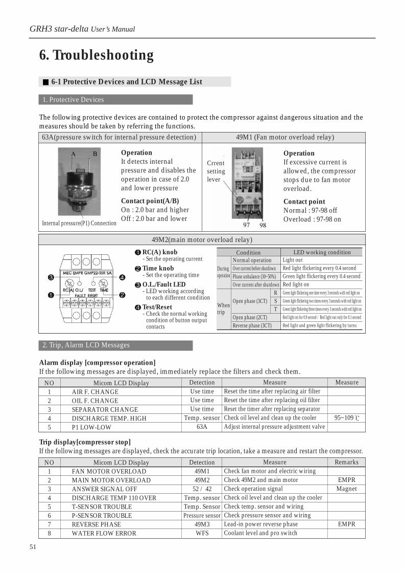
6-1 Protective Devices and LCD Message List
1. Protective Devices
The following protective devices are contained to protect the compressor against dangerous situation and themeasures should be taken by referring the functions.
2. Trip, Alarm LCD Messages
Alarm display [compressor operation]If the following messages are displayed, immediately replace the filters and check them.
63A(pressure switch for internal pressure detection) 49M1 (Fan motor overload relay)
Internal pressure(P1) Connection
OperationIt detects internalpressure and disables theoperation in case of 2.0and lower pressure
Contact point(A/B)On : 2.0 bar and higherOff : 2.0 bar and lower
Crrent setting lever
OperationIf excessive current isallowed, the compressorstops due to fan motoroverload.
Contact pointNormal : 97-98 offOverload : 97-98 on
DetectionUse timeUse timeUse time
Temp. sensor63A
NO12345
Micom LCD DisplayAIR F. CHANGEOIL F. CHANGESEPARATOR CHANGEDISCHARGE TEMP. HIGHP1 LOW-LOW
MeasureReset the time after replacing air filterReset the time after replacing oil filterReset the timer after replacing separatorCheck oil level and clean up the coolerAdjust internal pressure adjustment valve
Measure
95~109
Trip display[compressor stop]If the following messages are displayed, check the accurate trip location, take a measure and restart the compressor.
Detection49M149M2
52 / 42Temp. sensorTemp. SensorPressure sensor
49M3WFS
NO12345678
Micom LCD DisplayFAN MOTOR OVERLOADMAIN MOTOR OVERLOADANSWER SIGNAL OFFDISCHARGE TEMP 110 OVERT-SENSOR TROUBLEP-SENSOR TROUBLEREVERSE PHASEWATER FLOW ERROR
MeasureCheck fan motor and electric wiringCheck 49M2 and main motorCheck operation signalCheck oil level and clean up the coolerCheck temp. sensor and wiringCheck pressure sensor and wiringLead-in power reverse phaseCoolant level and pro switch
Remarks
EMPRMagnet
EMPR
6. Troubleshooting
GRH3 star-delta User’s Manual
RC(A) knob- Set the operating currentTime knob- Set the operating timeO.L./Fault LED- LED working according
to each different conditionTest/Reset- Check the normal working
condition of button output contacts
ConditionNormal operationOver current before shutdownPhase unbalance (30~50%)Over current after shutdown
Open phase (3CT)
Open phase (2CT)Reverse phase (3CT)
LED working conditionLight outRed light flickering every 0.4 secondGreen light flickering every 0.4 secondRed light onGreen light flickering one time every 3 seconds with red light onGreen light flickering two times every 3 seconds with red light onGreen light flickering three times every 3 seconds with red light onRed light on for 0.9 second / Red light out only for 0.1 secondRed light and green light flickering by turns

52 / HanShin
6. Troubleshooting
6-2 Trouble Causes and Measures
1. Fan motor overload, trip
Causes: fan motor overload or wrong connection of fan motor power cableCheckpoint: check the current and electric wiring
If overload is found as a result of measuring the current,check it as follows.
How to reset: press and then press [STOP] button on Micom.
Motor overcurrent -Check the fan rotation
by rotating it withhands
-Check the R/S/T phasesof the power cable.
If the current is normal, check theelectric wiring-If 97-98 is off after the power-off, the status
is normal -Check the current value setting( ) to see
whether the motor is set by the ratedcurrent.
2. Main motor overload, trip
Causes: main motor overload, 52 & 42 magnet contact point damage, voltage dropCheckpoint: Check the main motor rotation by rotating the air end with hands. How to reset: Press [STOP] button of Micom after taking a corrective measure.
3. High discharge air temperature, trip
Causes: high discharge air temperatureCheckpoint: refer to page 52 for compressor inhalation(ambient)
temperature, oil level, oil cooler and cleaning oil cooler. How to reset: Take a corrective measure and press [STOP] button of Micom.
4. Lead-in power reverse phase, trip(option)
-.With 49M2(EOCR), check whether the trip lamp is on.In case it’s on, it means overload, checking the mainmotor and supply voltage.
-.Check the power cable connection of 42&52 and themagnet’s contact point.
52 / Hanshin
Cause : Input power reverse phase detected or 49M2 troubledHow to check : Please replace the input cable if the red lamp
and green lamp of 49M2 flicker by turns. Pleaserefer to page 36 when replacing. If no. 97terminal and no. 98 terminal were contactedwhen the power is out, 49M2 is bad.
How to reset : Make it corrected and push the [STOP] button of Micom
O.L/Fault LED
Test/Reset button
Time knob
97~98 terminalsRC(A) knob
49M2(EMPR-Reverse phase detector)
53
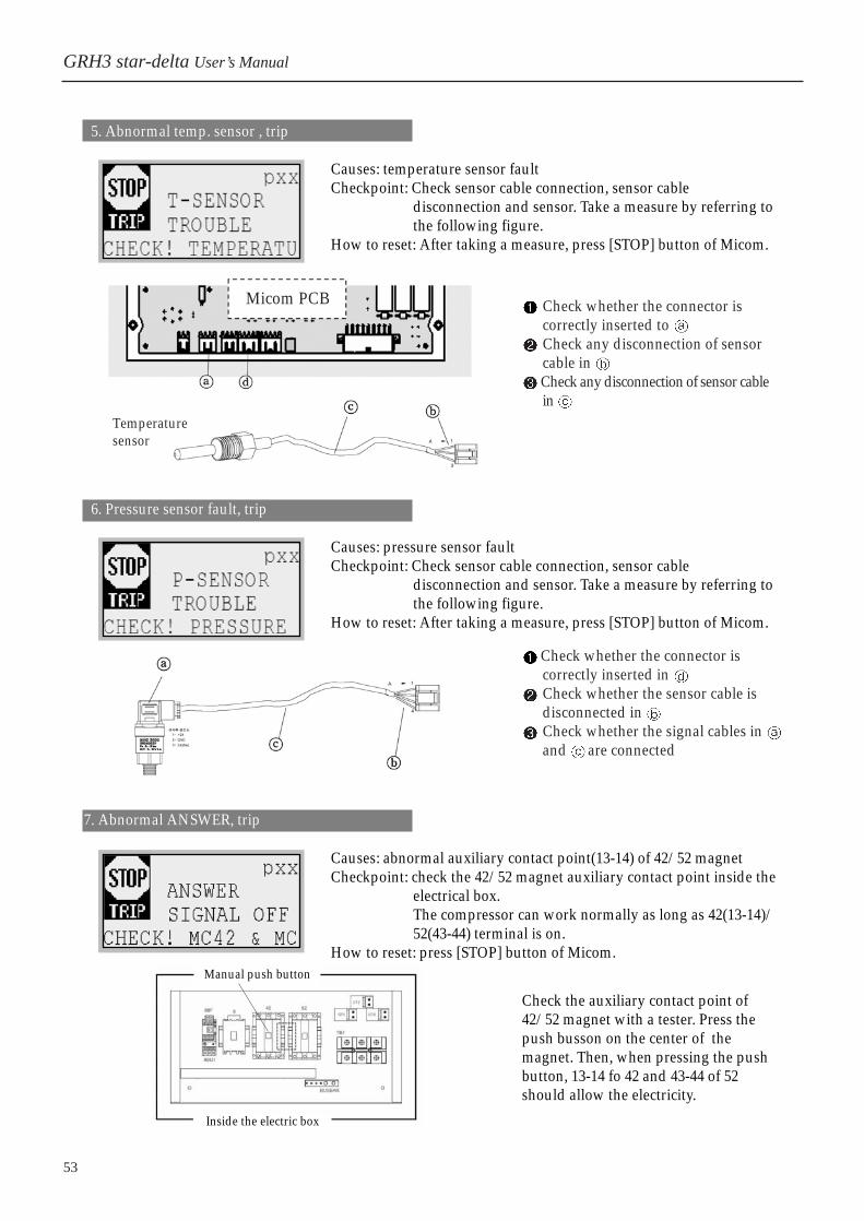
5. Abnormal temp. sensor , trip
Causes: temperature sensor fault Checkpoint: Check sensor cable connection, sensor cable
disconnection and sensor. Take a measure by referring tothe following figure.
How to reset: After taking a measure, press [STOP] button of Micom.
Check whether the connector iscorrectly inserted to Check any disconnection of sensorcable in Check any disconnection of sensor cablein
Temperaturesensor
6. Pressure sensor fault, trip
Causes: pressure sensor fault Checkpoint: Check sensor cable connection, sensor cable
disconnection and sensor. Take a measure by referring tothe following figure.
How to reset: After taking a measure, press [STOP] button of Micom.
Check whether the connector iscorrectly inserted in Check whether the sensor cable isdisconnected in Check whether the signal cables in and are connected
7. Abnormal ANSWER, trip
Causes: abnormal auxiliary contact point(13-14) of 42/52 magnet Checkpoint: check the 42/52 magnet auxiliary contact point inside the
electrical box.The compressor can work normally as long as 42(13-14)/52(43-44) terminal is on.
How to reset: press [STOP] button of Micom.
Check the auxiliary contact point of42/52 magnet with a tester. Press thepush busson on the center of themagnet. Then, when pressing the pushbutton, 13-14 fo 42 and 43-44 of 52should allow the electricity.
Manual push button
Inside the electric box
GRH3 star-delta User’s Manual
Micom PCB

54 / Hanshin
6. Troubleshooting
8. Troubleshooting flowchart
Trouble
The compressor does notstart even though pressing[START] button of Micom.
Is the red lamp on [TRIP]of Micom on?
Is the [STOP] lamp ofMicom controller on?
Is the start standby messagedisplayed on the LCD ofMicom controller?
Is the rated power suppliedto the compressor?
Is the schedule operationlamp on or is the scheduleoperation mode selelcted?
The compressor needsinspecting in detail. Pleasecontact your dealer or outA/S service center.
Defect power supply burnt fuse within Micom PCBFor fuse location, refer to page 34For control circuit, refer to page 64
High P1 internal pressure or63A switch faultHigh P2 pressure
Abnormal power orcontrol circuit
Schedule mode selectionSchedule operation
Main motor overload tripFan motor overload tripPressure sensor faultTemp. sensor faultMain motor reverse phaes
Checklist Potential trouble causes
Y
N
N
Y
N
Y
N
Y
N
Y

55
Trouble
The main motor rotates butthe pressure does not rise.
Is the belt or couplingcorrectly connected and is theair end properly rotating?
Is the inhalation valvecompletely open?
Does the sol valve soundwhen it opens.
Is the pressure indicationof Micom indicating 0 barand higher?
The compressor needsinspecting in detail. Pleaecontact your dealer or ourA/S service center.
Inhalation valve fault
The belt is cut offThe coupling isseparated
Abnormal sol valveoperation signal
Abnormal sol valve
Checklist Potential trouble causes
N
N
Pressure sensor fault
N
Y
Y
Y
Y
N
GRH3 star-delta User’s Manual

56 / Hanshin
6. Troubleshooting
Trouble
The safety valve suddenlyoperates during operation
Does the safety valve operatewithin the rated pressure?
Is the operation pressure setbelow the rated pressure?
Re-set the pressureaccording to the ratedpressure.
Is the front/end diff.pressure of the separatorwithin 1.0 bar?
Is the pressure suddenlychanged and indicated?
Is the Micom’s pressureindicating 0.0 bar duringoperation?
The pressure sensor isdetached from Micom.Or, the sensor cable orsensor is in trouble.
The compressor needsinspecting in detail. Pleaecontact your dealer or ourA/S service center.
Safety valve fault
Checklist Potential trouble causes
Y
N
Oil separator is blocked
Pressure sensor fault
Y
Y
N
Y
Y
N
N
N
7-1 Regular Maintenanc
1. Routine operation control
Please record the daily operation details in the compressor operation log. Maintain the compressor if any values higher than the settings are found.
2 . Regular maintenance
1) For the maintenance criteria, refer to the maintenance list. Depending on the environment situation of installation place, the compressor may be necessarily maintained earlier than the standard maintenance.
2) If any abnormal parts are found during the maintenance, promptly replace them.
3) Make sure to replace them with the company’s genuine parts.
3. Motor protection and maintenance
1) Temperature riseThe temperature rise limit of the motor coil is 125°…(based on 40°… ambient temperature). If the motoroverheats even under normal load operation, check the motor immediately(refer to the motor°Øsspecifications).
2) Cleaning and insulation resistance checkFrequently clean it up to prevent dust or impurities from inserting to the motor. By measuring the motor winding with 500V insulation resistance tester during regular check, checkwhether it indicates 10 and higher, which is the normal status).
3) Greasing the motorFor the motor grease level and the interval, refer to the motor specifications.
7. Maintenance
Before maintenance and check, read [About Safety] carefully.Every time you maintain the compressor, make sure to turn off the power. Or, itmay cause unexpected accidents such as electric shock.When coupling or disassembling parts, discharge the internal pressure to the air.In case detaching bolts and pipes, it may cause a trouble due to internallyremaining pressure.
Caution
57
GRH3 star-delta User’s Manual

58 / Hanshin
7. Maintenance
7-2 Maintenance Methods
1. Replacement and cleaning of inhalation filter / 3000hr
The inhalation filter diff. pressure during operationis 4.98kpa [508mmH2O]. The inhalation filtershould be maintained according to the standardmaintenance criteria.
Open the front left of the sound proof cover.Open the inhalation filter cover and detach thefilter.After detaching the filter, a special attentionshould be paid to avoid any impurities or dustfrom inserting into the inhalation valve. Clean the compressor air to clean up theinhalation filter.If it is time to replace the filter, immediatelyreplace the filter.
Open the front left of the sound proof cover.
Open the drain valve located at the bottom ofthe separator tank, discharge the used lubricantand then, close it again.
Open the lubricant inlet and replenishlubricant. Keep inserting it until it indicates theupper limit.
If lubricant is completely replenished, operatethe compressor, stop it, check the flowmeterand replenish it more if the level is notsufficient.
Open the front left of the sound proof cover.
Loosen the oil filter by using chain wrench orother tools.
To couple the oil filter, apply small quantity ofoil on O-ring by hands and smoothly tighten itby using wrench or other tools.
Visually check whether it has any oil leakagewhile operating the compressor.
Inhalation filtercover
Inahaltion filter
Separator tank
Lubricant inlet
Flowmeter
Drain valve
Oil filter
59
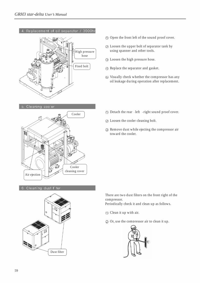
Open the front left of the sound proof cover.
Loosen the upper bolt of separator tank byusing spanner and other tools.
Loosen the high pressure hose.
Replace the separator and gasket.
Visually check whether the compressor has anyoil leakage during operation after replacement.
Detach the rear left right sound proof cover.
Loosen the cooler cleaning bolt.
Remove dust while ejecting the compressor airtoward the cooler.
There are two dust filters on the front right of thecompressor. Periodically check it and clean up as follows.
Clean it up with air.
Or, use the compressor air to clean it up.
High pressurehose
Fixed bolt
Cooler
Coolercleaning cover
Air ejection
Dust filter
GRH3 star-delta User’s Manual

60 / Hanshin
8. Control System
8-1 Compressor Configuration Layout
8. Control System

61
8-2 Control circuit
1. Analogue Controller (ACP-2007) GRH3-20A~35A
Cau
tion!
If [S
TART
] an
d [S
TOP]
lam
ps a
re s
imul
tane
ousl
y on
, it
mea
ns t
hat
the
com
pres
sor
stop
s du
e to
the
inte
rnal
pres
sure
ris
e. W
hen
you
repa
ir o
r m
aint
ain
the
com
pres
sor,
plea
se n
ote
that
the
com
pres
sor
auto
mat
ical
lyre
star
ts if
the
pres
sure
falls
few
er th
an 2
.0 b
ar.
CO
NTR
OL
PAN
AL
GRH3 star-delta User’s Manual

62 / Hanshin
8. Control System
2. Micom Controller GRH3-50A~100A

63
GRH3-25A, 30A, 35A, 50A Star-delta
GRH3 star-delta User’s Manual
64 / Hanshin
8. Control System
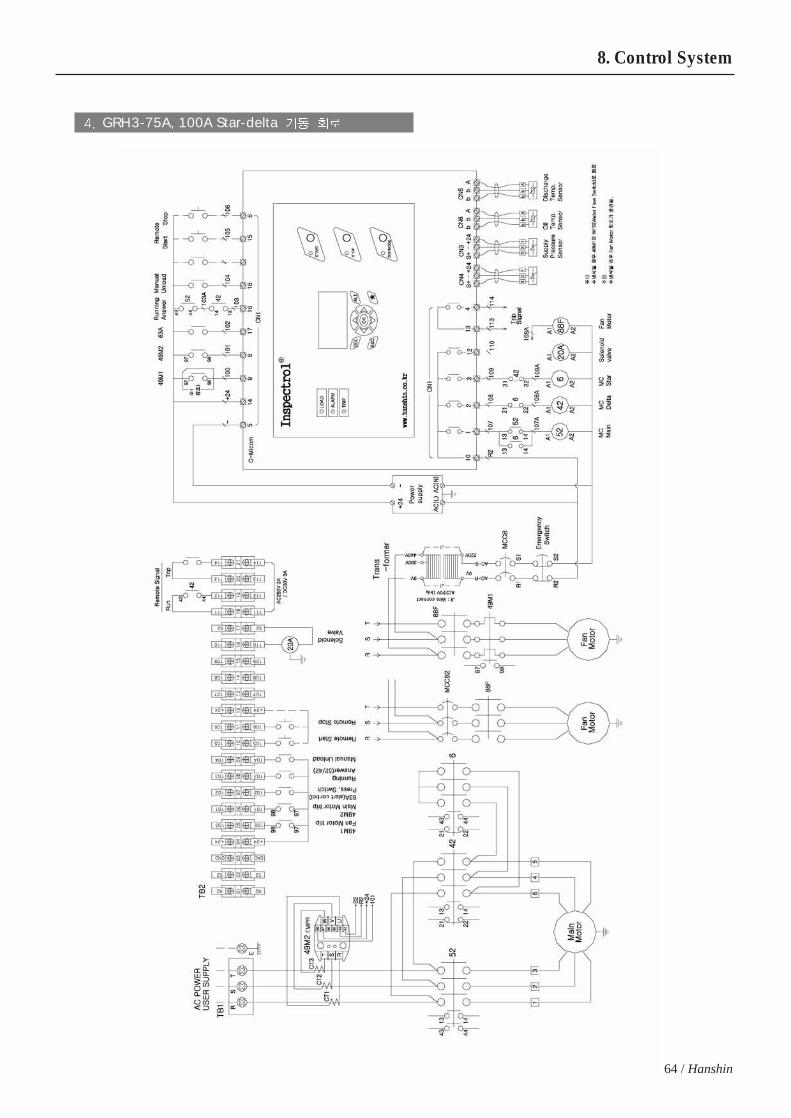
GRH3-75A, 100A Star-delta
65
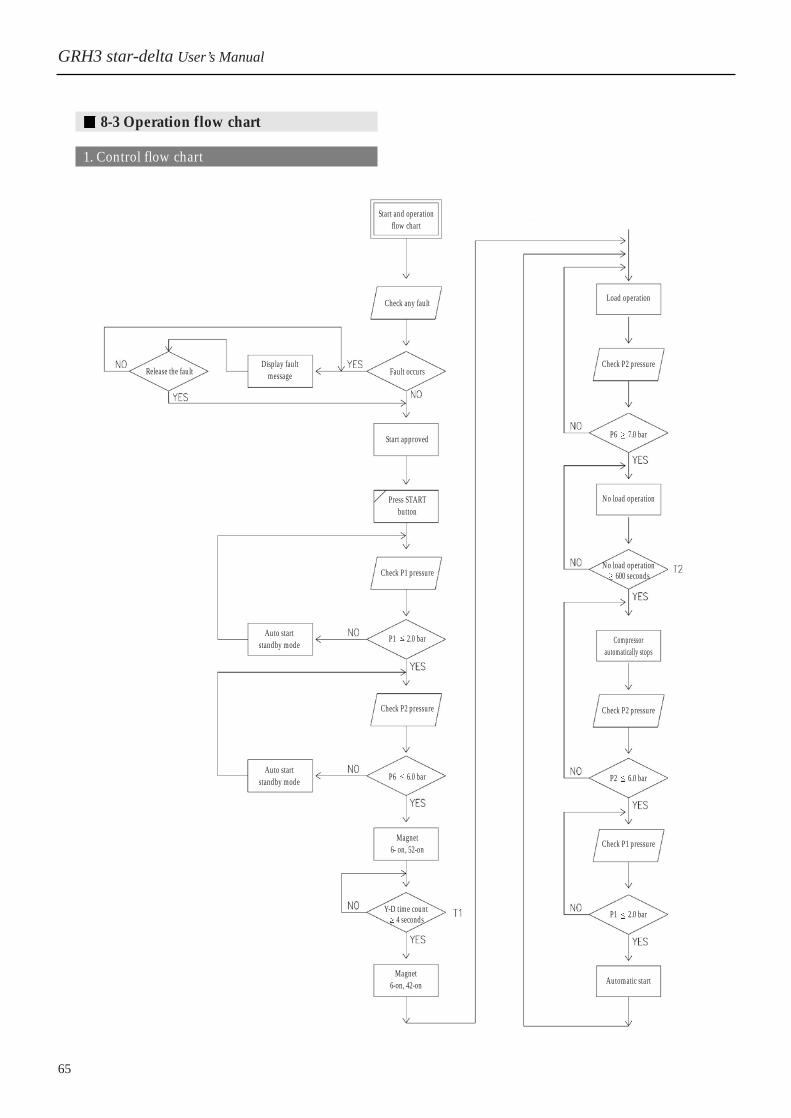
8-3 Operation flow chart
1. Control flow chart
GRH3 star-delta User’s Manual
Start and operationflow chart
Release the faultDisplay fault
message
Check any fault Load operation
Check P2 pressure
P6 7.0 bar
No load operation
No load operation600 seconds
Compressorautomatically stops
Check P2 pressure
P2 6.0 bar
Check P1 pressure
P1 2.0 bar
Automatic start
Fault occurs
Start approved
Press STARTbutton
Auto start standby mode
Auto start standby mode
Check P1 pressure
P1 2.0 bar
Check P2 pressure
P6 6.0 bar
Magnet 6- on, 52-on
Y-D time count 4 seconds
Magnet 6-on, 42-on

66 / Hanshin
8. Control System
2. Pressure Control Graph(Operation setting pressure: 7.0bar)
Section: compressor load operation section If P2 pressure is lower than the no-load start pressure after the compressor starts, it starts load operation.
Sections: compressor no-load operation sectionIf P2 pressure is higher than the no-load start pressure, it operates under no load up to 6.0bar; if lower than6.0 bar, it returns to load operation.
Section: auto stop sectionIf no-load operation lasts over 10 minutes in section, the compressor automatically stops; if P2 pressurefalls under 6.0 bar, the compressor automatically starts.
and : internal pressure purge sectionThe internal pressure(P1) during no-load operation falls up to 2.0 bar; if it automatically stops, the internalpressure falls up to 0 bar.
Position: automatic restartIf P2 pressure falls lower than 6.0 bar after auto stop, the compressor automatically starts.
Pressure variation of each part during the operation and at the auto stop
Status
Operation
condition
Operation conditionLoad operation
No Load operationAuto stop
P1
2.0 bar0 bar
Normal if pressure variation is within 1barP2
6~7 bar6~7 bar
<Pressure spec.:7bar>
P1:Internal pressureP2:Pressure in use
Discharge presusre(bar)
Time

8-4 Arrangement Diagram and Spec. of Control Parts
1. Inside View of Electrical Box GRH3-20A, 25A, 30A, 35A, 50A
GRH3 star-delta User’s Manual
67
MCCB
2T2
MCCBPower supply
Transformer52X
TB2
Transformer
TB2
49M2
CT
TB1
CT
6
TB1
2T1
88F49M1
88F49M1
42 52
6 42 52
Analog controller
Micom controller
63AX26X
49M2
Controller
Emergency Stop button
Power cable lead-in opening

2. Inside View of Electrical Box(Micom Controller) GRH3-75A,100A
68 / Hanshin
TB2 Transformer
MCCB1
MCCB2
Power supply
CT
TB1
Transformer
Power supply
49M2
CT
TB1
52
42
6
88F
49M2
TB2
MCCB
52426
88F
49M1
GRH3-75A, 100A
GRH3-75W, 100W
8. Control System
69
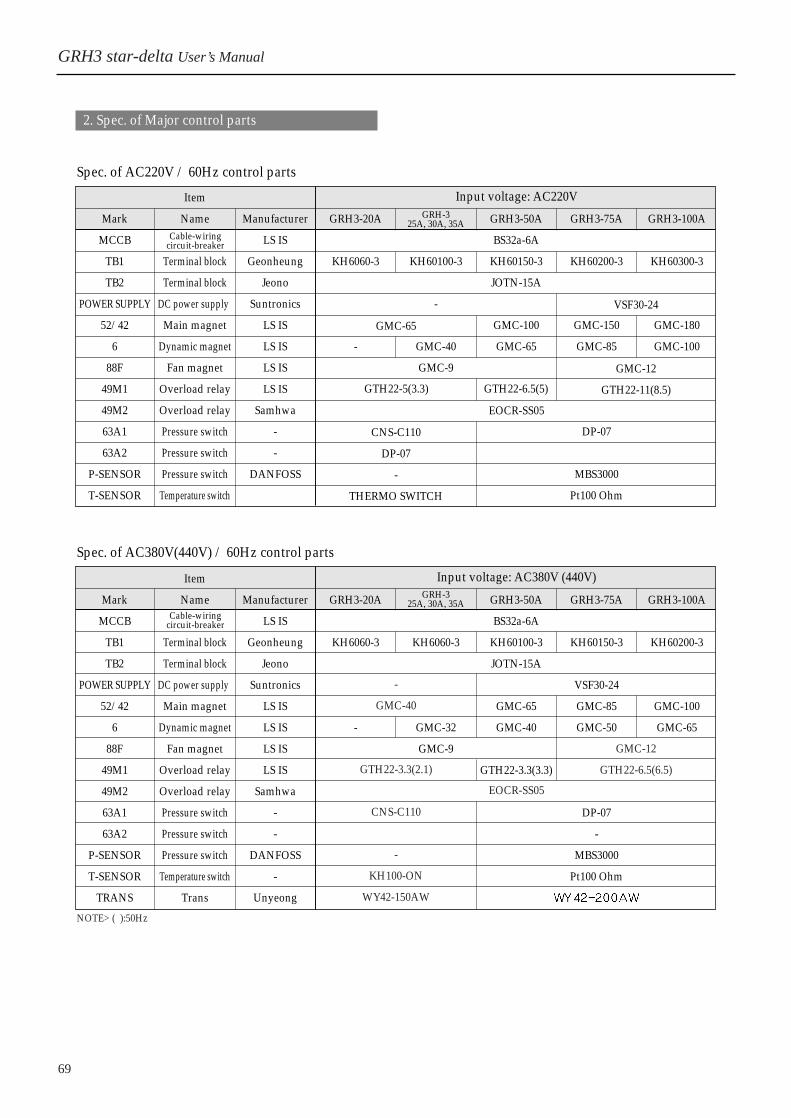
2. Spec. of Major control parts
Spec. of AC220V / 60Hz control parts
Spec. of AC380V(440V) / 60Hz control parts
Mark
MCCB
TB1
TB2
POWER SUPPLY
52/42
6
88F
49M1
49M2
63A1
63A2
P-SENSOR
T-SENSOR
Item
Name
Terminal block
Terminal block
DC power supply
Main magnet
Dynamic magnet
Fan magnet
Overload relay
Overload relay
Pressure switch
Pressure switch
Pressure switch
Temperature switch
Manufacturer
LS IS
Geonheung
Jeono
Suntronics
LS IS
LS IS
LS IS
LS IS
Samhwa
-
-
DANFOSS
GRH3-20A
KH6060-3
-
KH60100-3
-
GMC-40
GMC-9
GRH3-50A
BS32a-6A
KH60150-3
JOTN-15A
GMC-100
GMC-65
GRH3-75A
KH60200-3
GMC-150
GMC-85
DP-07
MBS3000
Pt100 Ohm
GRH3-100A
KH60300-3
GMC-180
GMC-100
GRH-325A, 30A, 35A
Cable-wiringcircuit-breaker
Cable-wiringcircuit-breaker
Input voltage: AC220V
EOCR-SS05
GTH22-5(3.3) GTH22-6.5(5)
VSF30-24
GMC-12
GTH22-11(8.5)
GMC-65
CNS-C110
DP-07
-
THERMO SWITCH
Mark
MCCB
TB1
TB2
POWER SUPPLY
52/42
6
88F
49M1
49M2
63A1
63A2
P-SENSOR
T-SENSOR
TRANS
Item
Name
Terminal block
Terminal block
DC power supply
Main magnet
Dynamic magnet
Fan magnet
Overload relay
Overload relay
Pressure switch
Pressure switch
Pressure switch
Temperature switch
Trans
Manufacturer
LS IS
Geonheung
Jeono
Suntronics
LS IS
LS IS
LS IS
LS IS
Samhwa
-
-
DANFOSS
-
Unyeong
GRH3-20A
KH6060-3
-
KH6060-3
GMC-32
GMC-9
GRH3-50A
BS32a-6A
KH60100-3
JOTN-15A
GMC-65
GMC-40
GTH22-3.3(3.3)
GRH3-75A
KH60150-3
VSF30-24
GMC-85
GMC-50
DP-07
-
MBS3000
Pt100 Ohm
GRH3-100A
KH60200-3
GMC-100
GMC-65
GRH-325A, 30A, 35A
Input voltage: AC380V (440V)
EOCR-SS05
GMC-12
GTH22-6.5(6.5)
-
GMC-40
GTH22-3.3(2.1)
CNS-C110
-
KH100-ON
WY42-150AW
NOTE> ( ):50Hz
GRH3 star-delta User’s Manual

70 / Hanshin
9. Specifications
9. Specifications
GRH320A
2.4
2.2
2.0
Direct
15
66
673
GRH325A
3.0
2.7
2.4
18
67
700
GRH330A
3.6
3.3
3.0
22
68
726
GRH335A
4.3
4.0
3.7
27
4
50/60
IP22
MAX. 40
69
753
GRH350A
6.7
5.8
5.3
25
40A
37
1.6
70
1100
1600
1500
940
GRH375A
10.3
9.1
8.3
55
72
1596
GRH3100A
13.6
12.0
10.7
75
73
1713
TYPE
7.0 bar
8.5 bar
9.9 bar
OIL CAPACITY( )
DRIVING METHOD
STARTING
CONNECT PIPE SIZE
MOTOR POWER(kW)
POLES(P)
VOLTAGE(V)
FREQUENCY(Hz)
PROTECTION DEGREE
FAN MOTOR(kW)
SERVICE AIR TEMP.( )
ALLOWABLE AMBIENT TEMP.( )
NOISE LEVEL
Width(mm)
Depth(mm)
Height(mm)
Weight(kg)
Single Stage Oil Injection Screw Air Compressor
CAPACITYFAD*(m3/min)
CO
MP
RE
SS
OR
MO
TO
RG
RN
ER
AL
DIM
EN
SIO
N
15
25A
1.1
AC220, 380, 440 3 Phase
Ambient Temperature + 15
50A
1.6x2
Belt driven
Star-Delta Starter
50
Gear driven
1000
1400
1350
2000
1350
1700
NOTE> DIMENSION and other data may change for the performance improvement.
Model

71
Check
Check
Check
Check
Check
Check/replace
Check
Replace
Replace
Replace
Replace
Check
1 mth
500h
Check
2 mths
1000h
6 mths
3000h
1 yr
6000h
2 yrs
12000h
4 yrs
24000h
Temp. Pressure
Electric box
Protective/safety devices
Power cable deterioration
Magnet
Oil leakage
Oil surface
Air filter
Oil Filters
Oil separator
Oil
Belt and coupling
Safety valve operation
Abnormal noise/vibration
Insulation
Bearing
Grease
Bearing
Oil seal
O-ring
Rotor
Oil cooler
After cooler
10. Maintenance Checklist
Checkpoint
Daily
Check period
Parts to check
Check indication
Cleaning if there is built-in dust
Check indication
Visually check coupling status
Check cable’s tightness
Replenish if insufficient
3000Hr
Replacement in the first 500h
If differential pressure is 1.0bar and higher
Replacement in the first 500h
Check tension/separation
Refer to motor’s spec.
Refer to motor’s spec.
4 years
4 years
4 years
Notes
Check or cleaning Replacement
GRH3 star-delta User’s Manual
Elec
tric
con
trol
Oil
& F
ilter
sM
achi
neM
ain
Mot
orA
ir e
ndC
oole
r

72 / Hanshin
10. Maintenance Checklist 11. Operation Log
11. Operation LogO
pera
tion
Ope
ratio
nho
urs
Dis
char
gepr
essu
reD
ischa
rge
tem
pera
ture
Lubr
ican
tN
oise
Vol
tage
Not
esC
urre
nt
R
S
TDa
te of
Che
ck
(
)MM
(
)DD
(
)MM
(
)DD
(
)MM
(
)DD
(
)MM
(
)DD
(
)MM
(
)DD
(
)MM
(
)DD
(
)MM
(
)DD
(
)MM
(
)DD
(
)MM
(
)DD
(
)MM
(
)DD
(
)MM
(
)DD
(
)MM
(
)DD
(
)MM
(
)DD
(
)MM
(
)DD
(
)MM
(
)DD
(
)MM
(
)DD
(
)MM
(
)DD
(
)MM
(
)DD
(
)MM
(
)DD
Ope
ratio
n Lo
g
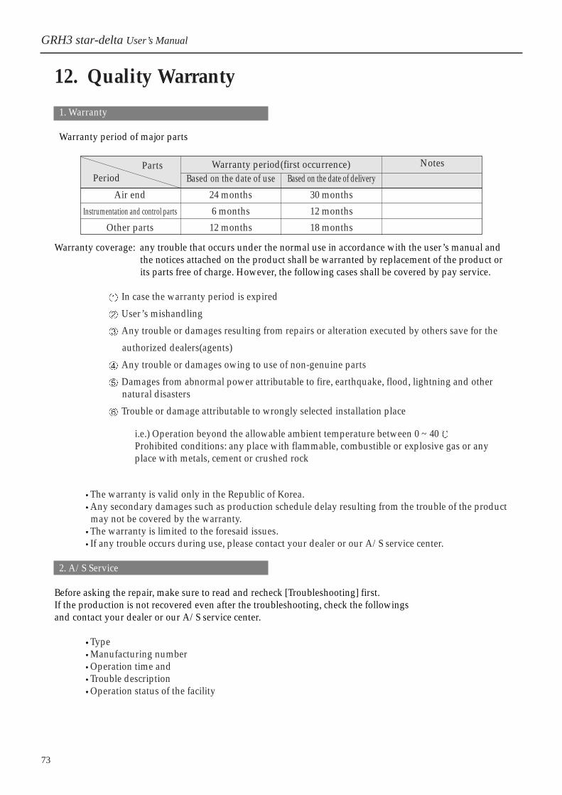
73
1. Warranty
Warranty period of major parts
Warranty coverage: any trouble that occurs under the normal use in accordance with the user’s manual andthe notices attached on the product shall be warranted by replacement of the product orits parts free of charge. However, the following cases shall be covered by pay service.
In case the warranty period is expired
User’s mishandling
Any trouble or damages resulting from repairs or alteration executed by others save for the
authorized dealers(agents)
Any trouble or damages owing to use of non-genuine parts
Damages from abnormal power attributable to fire, earthquake, flood, lightning and other natural disasters
Trouble or damage attributable to wrongly selected installation place
i.e.) Operation beyond the allowable ambient temperature between 0 ~ 40Prohibited conditions: any place with flammable, combustible or explosive gas or anyplace with metals, cement or crushed rock
The warranty is valid only in the Republic of Korea.Any secondary damages such as production schedule delay resulting from the trouble of the product may not be covered by the warranty.The warranty is limited to the foresaid issues. If any trouble occurs during use, please contact your dealer or our A/S service center.
2. A/S Service
Before asking the repair, make sure to read and recheck [Troubleshooting] first. If the production is not recovered even after the troubleshooting, check the followings and contact your dealer or our A/S service center.
TypeManufacturing numberOperation time and Trouble descriptionOperation status of the facility
12. Quality Warranty
Air end
Instrumentation and control parts
Other parts
Based on the date of use
24 months
6 months
12 months
Based on the date of delivery
30 months
12 months
18 months
NotesParts Warranty period(first occurrence)Period
GRH3 star-delta User’s Manual

74 / Hanshin
12. Quality Warranty 13. Outside Drawing by Models
1. GRH3-20A, 25A, 30A, 35A
13. Outside Drawing by Models

75
2. GRH3-50A
GRH3 star-delta User’s Manual

76 / Hanshin
13. Outside Drawing by Models
3. GRH3-75A, 100A

4. GRH3-75W, 100W
GRH3 star-delta User’s Manual
77
Appearance
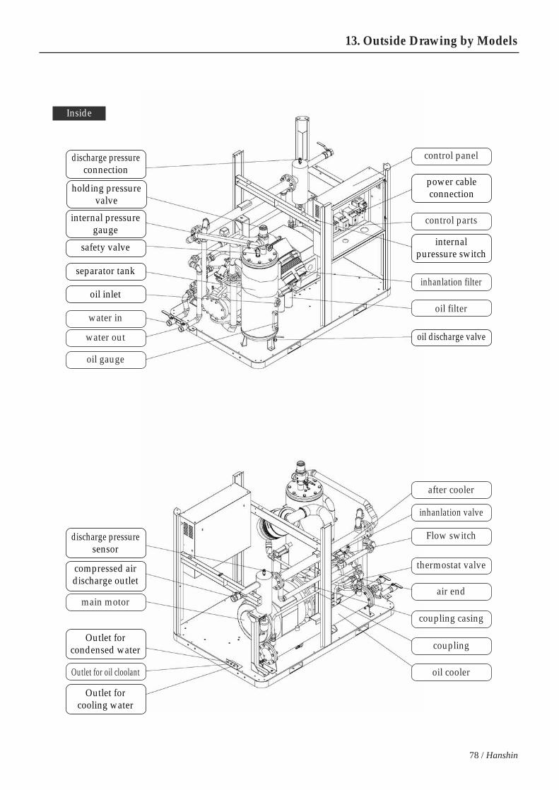
13. Outside Drawing by Models
78 / Hanshin
water in
water out
oil gauge
main motor
Outlet for oil cloolant
control panel
control parts
inhanlation filter
oil filter
after cooler
inhanlation valve
Flow switch
thermostat valve
air end
coupling casing
coupling
oil cooler
Inside
power cableconnection
oil inlet
oil discharge valve
discharge pressureconnection
holding pressurevalve
safety valve internalpuressure switch
separator tank
internal pressuregauge
compressed airdischarge outlet
discharge pressuresensor
Outlet forcondensed water
Outlet forcooling water