User’s Manual PDO 5580 Step Motor Driver motors • drives • controls PDO 5580 Step Motor Driver 50% IDLE JOYSTICK EXT SPEED 0.2 0.4 0.8 1.6 2.0 CURRENT HIGH SPEED LOW SPEED STEPS/REV ACCEL SELF TEST OSC BYPASS (BASE = 0.5 A) SHORT TEMP POWER DIR+ DIR– STEP+ STEP– EN+ EN– FAULT+ FAULT– SPEED+ SPEED- TACH+ TACH– CW WPR CCW B– B+ A– A+ MOTOR N G L AC POWER 90V pk 6 5 7 8 4 3 2 1 6 5 4 3 2 1
Transcript
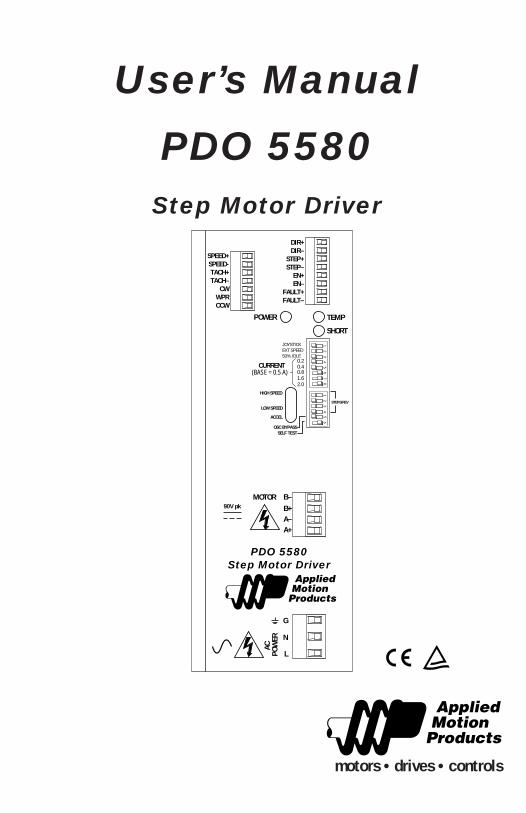
User’s Manual
PDO 5580Step Motor Driver
motors • drives • controls
PDO 5580Step Motor Driver
50% IDLE
JOYSTICKEXT SPEED
0.20.40.81.62.0
CURRENT
HIGH SPEED
LOW SPEEDSTEPS/REV
ACCEL
SELF TESTOSC BYPASS
(BASE = 0.5 A)
SHORT
TEMPPOWER
DIR+DIR–
STEP+STEP–
EN+EN–
FAULT+FAULT–
SPEED+SPEED-TACH+TACH–
CWWPRCCW
B–B+A–A+
MOTOR
N
G
L
AC P
OWER
90V pk
65
78
43
21
65
43
21
Applied Motion Products, Inc.404 Westridge Drive Watsonville, CA 95076
Tel (831) 761-6555 (800) 525-1609 Fax (831) 761-6544
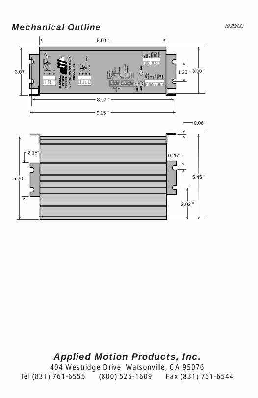
8/28/00Mechanical Outline
PD
O 5
58
0S
tep
Mo
tor D
river
50% IDLE
JOYSTICKEXT SPEED
0.20.40.81.62.0
CURRENT
HIGH SPEED
LOW SPEED
STEPS/REV
ACCELSELF TESTOSC BYPASS
(BASE = 0.5 A)
SHORT
TEMP
POWER
DIR+DIR–
STEP+STEP–
EN+EN–
FAULT+FAULT–
SPEED+SPEED-TACH+TACH–
CWW
PRCCW
B–B+A–A+
MOTOR
N GL
AC POWER
90V pk
6 578 4 3 2 16 5 4 3 2 1
3.07 "
8.00 "
3.00 " 1.25 "
8.97 "
9.25 "
5.45 " 5.30 "
2.02 "
0.25"
0.06"
2.15"
-2-
IntroductionThank you for selecting an Applied Motion Products motor control. We hope ourdedication to performance, quality and economy will make your motion controlproject successful. If there’s anything we can do to improve our products or help youuse them better, please call or fax. We’d like to hear from you. Our phone number is(800) 525-1609 or you can reach us by fax at (831) 761–6544.
Features
• Digital oscillator provides smooth accel/decel ramps and precise speed control.• Powerful microstepping amplifier provides high torque and smooth, quiet motion.• Accepts a wide range of motors: NEMA sizes 14 - 42, 0.5 to 5.5 amps/phase.• Easy to configure with on-board switches and potentiometers for all settings.• Automatic idle current reduction reduces motor and drive heating, saves power.• Pluggable screw terminal connectors make wiring easy.• Oscillator Mode operates from internal pots, external pots, 0 - 5 V analog signal,
or analog joystick.• Two speed ranges, can be selected “on the fly” by a digital signal with automatic
ramping between speeds.• Inputs and outputs are optically isolated, differential (sourcing or sinking). Speed
& Enable 5 - 24V, Step & Direction 5 - 12V.• Tach Out signal allows easy measurement of speed.• Enable input allows motor current to be shut off on command.• Built in 80 volt power supply (accepts 110 or 220 VAC power, 50-60 Hz)• MOSFET pulse width modulation switching amplifiers (3 state)• Microstepping pulse & direction mode with 16 step/rev settings from 200 (full
step) through 50,800.• Overtemp and overcurrent (short circuit) and surge protection• Built-in self test for troubleshooting.• CE and TUV compliant.
-23-
Technical Specifications (continued)
RecommendedJoystick
Speed Ranges
Physical
Connectors
CE Mark
Maurey Instrument Corp., Chicago, IL (773)581-4555JS31462S5T3 (2 axis) or SAJ2515-F-502 (1 axis)
LO speed range: 0 - 5 rev/secHI speed range: 0 - 25 rev/secAccel/decel range: 1 to 250 rev/sec/sec
Constructed with black anodized aluminum heat sink and heavygauge steel housing. 3 x 5.3 x 8 inches overall. 7.8 lbs. Ambienttemperature range: 0 - 70 C. Power, temp and motor short circuitLEDs. Mounting brackets and switch cover included. See backcover for detailed drawing .
Complies with EN55011A, EN50082-1(1996), EN50178 (1997).
-3-
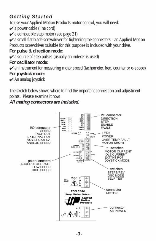
Getting StartedTo use your Applied Motion Products motor control, you will need: a power cable (line cord) a compatible step motor (see page 21) a small flat blade screwdriver for tightening the connectors - an Applied MotionProducts screwdriver suitable for this purpose is included with your drive.For pulse & direction mode: a source of step pulses (usually an indexer is used)For oscillator mode: an instrument for measuring motor speed (tachometer, freq. counter or o-scope)For joystick mode: An analog joystick
The sketch below shows where to find the important connection and adjustmentpoints. Please examine it now.All mating connectors are included.
Dual, MOSFET H-bridge, 3 state, pulse width modulated switchingat 20 kHz. 0.5 - 5.5 amps/phase output current, switchselectable in 0.2 increments. Overcurrent and overtemperatureprotection. Automatic idle current reduction (defeatable), reducescurrent to 50% of setting after one second. Minimum motorinductance is 0.8 mH.
Linear, toroidal transformer based for high reliability and lownoise. 110 or 220 VAC input, switch selectable. 50-60 Hz.DC voltage at nominal line voltage: 75 VDC full load, 90 VDC noload.
Wiper: 0 - 5 VDC analog signal. Max recommended pot/joystickimpedance: 1K - 5K ohms. Joystick dead zone: ± 80 mV.Potentiometer/analog signal dead zone: 40 mV.
In pulse & direction mode, motor steps on falling edge of stepinput. 0.25 µsec minimum pulse, 2 MHz max step rate. 1 µsecminimum set up time, 50µs minimum hold time for directionsignal.
Tach & Fault: Optically isolated, uncommitted (open collector,open emitter) photo transistors. 30V, 20 mA max. Tach output is100 pulses per motor revolution, 50% duty cycle (square wave).
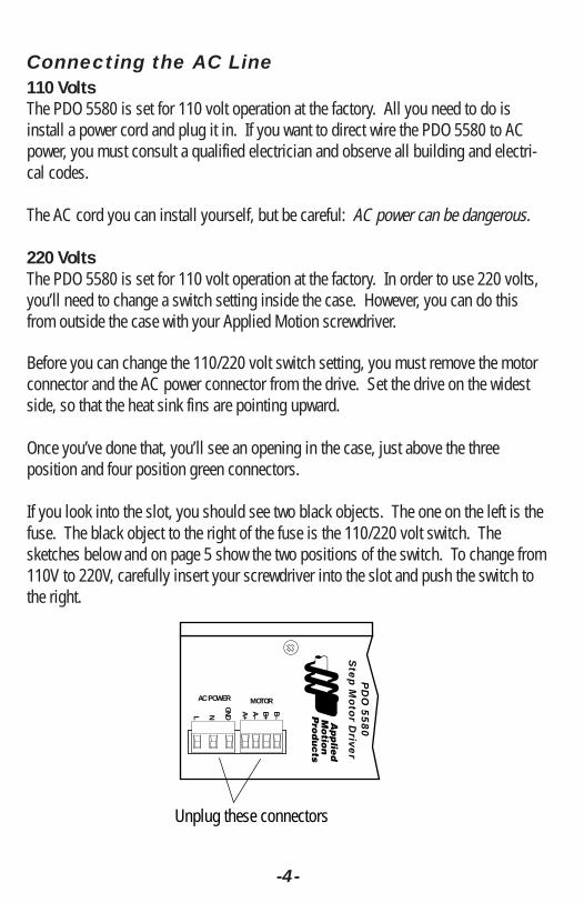
Before you can change the 110/220 volt switch setting, you must remove the motorconnector and the AC power connector from the drive. Set the drive on the widestside, so that the heat sink fins are pointing upward.
Once you’ve done that, you’ll see an opening in the case, just above the threeposition and four position green connectors.
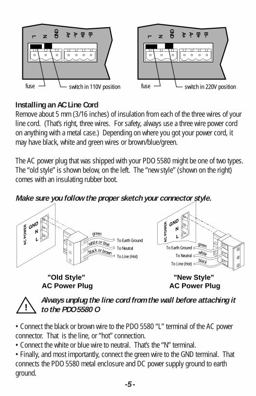
If you look into the slot, you should see two black objects. The one on the left is thefuse. The black object to the right of the fuse is the 110/220 volt switch. Thesketches below and on page 5 show the two positions of the switch. To change from110V to 220V, carefully insert your screwdriver into the slot and push the switch tothe right.
Connecting the AC Line110 VoltsThe PDO 5580 is set for 110 volt operation at the factory. All you need to do isinstall a power cord and plug it in. If you want to direct wire the PDO 5580 to ACpower, you must consult a qualified electrician and observe all building and electri-cal codes.
The AC cord you can install yourself, but be careful: AC power can be dangerous.
220 VoltsThe PDO 5580 is set for 110 volt operation at the factory. In order to use 220 volts,you’ll need to change a switch setting inside the case. However, you can do thisfrom outside the case with your Applied Motion screwdriver.
B–B+A–A+
MOTORGNDNL
AC POWER
Unplug these connectors
PD
O 5
58
0S
tep
Mo
tor D
river
-21-
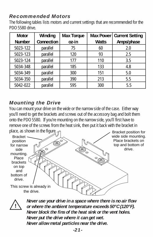
Recommended MotorsThe following tables lists motors and current settings that are recommended for thePDO 5580 drive.
Motor Winding Max Torque Max Power Current SettingNumber Connection oz-in Watts Amps/phase5023-122 parallel 75 60 2.05023-123 parallel 120 93 2.55023-124 parallel 177 110 3.55034-348 parallel 185 133 4.85034-349 parallel 300 151 5.05034-350 parallel 390 213 5.55042-022 parallel 595 300 5.5
Never use your drive in a space where there is no air flowor where the ambient temperature exceeds 50°C (120°F).Never block the fins of the heat sink or the vent holes.Never put the drive where it can get wet.Never allow metal particles near the drive.
!
Bracket position forwide side mounting.Place brackets ontop and bottom of
drive.
Bracketposition
for narrowside
mounting.Place
bracketson top
andbottom of
drive.
This screw is already inthe drive.
Mounting the DriveYou can mount your drive on the wide or the narrow side of the case. Either wayyou’ll need to get the brackets and screws out of the accessory bag and bolt themonto the PDO 5580. If you’re mounting on the narrow side, you’ll first have toremove one of the screws from the heat sink, then put it back with the bracket inplace, as shown in the figure.
-5-
Installing an AC Line CordRemove about 5 mm (3/16 inches) of insulation from each of the three wires of yourline cord. (That’s right, three wires. For safety, always use a three wire power cordon anything with a metal case.) Depending on where you got your power cord, itmay have black, white and green wires or brown/blue/green.
The AC power plug that was shipped with your PDO 5580 might be one of two types.The “old style” is shown below, on the left. The “new style” (shown on the right)comes with an insulating rubber boot.
Make sure you follow the proper sketch your connector style.
•Connect the black or brown wire to the PDO 5580 “L” terminal of the AC powerconnector. That is the line, or “hot” connection.•Connect the white or blue wire to neutral. That’s the “N” terminal.•Finally, and most importantly, connect the green wire to the GND terminal. Thatconnects the PDO 5580 metal enclosure and DC power supply ground to earthground.
!
kcalbetihwneerg
To Earth Ground
To Neutral
To Line (Hot)
To Earth Ground
To Neutral
To Line (Hot)
green
black or brown
whit e or blue
"Old Style" AC Power Plug
"New Style" AC Power Plug
B–B+A–A+
GNDNL
switch in 110V positionfuse
B–B+A–A+
GNDNL
switch in 220V positionfuse
Always unplug the line cord from the wall before attaching itto the PDO 5580 O
-20-
Fault Protection
The PDO 5580 provides protection against motor short circuits and excessive drivetemperature.
If the TEMP light is on, the PDO 5580 has detected a thermal problem and shut downthe amplifiers. The first thing you should do is to unplug the drive from the powersource. Next, touch the heat sink with your fingers. If it is very hot, the drive hasprobably overheated. Usually this means you need more air flow around the drive.
If the SHORT light is on, the PDO 5580 has detected a short circuit and has shutdown the amplifiers. Unplug the drive from the power source. Check the motorwiring carefully. Make sure that the connections to the drive are secure and that anyunused motor leads are insulated from the drive and power supply and from eachother. Check the motor leads for shorts between phases or to ground.
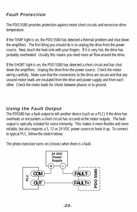
Using the Fault OutputThe PD5580 has a fault output to tell another device (such as a PLC) if the drive hasoverheats or encounters a short circuit has occured at the motor outputs. The faultoutput is optically isolated for noise immunity. This makes it more flexible and morereliable, but also requires a 5, 12 or 24 VDC power source to hook it up. To connectto typical PLC, follow the sketch below.
The photo transistor turns on (closes) when there is a fault.
24 VDCPowerSupply
PD
O 5
580
FAULT-
PLC
FAULT+OUT
COM
-+
-6-
A+
A–
NC
B+B– NC
6leadmotor
RedBlack
Red/Wht
Green
Grn/Wht
White A+
A–
NC
B+B– NC
6lead
motor
Grn/Wht
White
Green
RedRed/Wht
Black
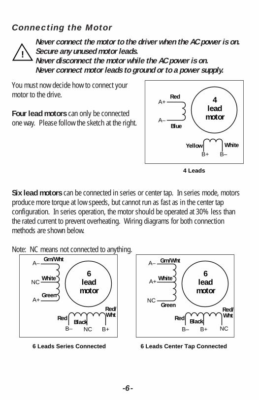
6 Leads Series Connected 6 Leads Center Tap Connected
A+
A–
B+ B–
4lead
motor
Red
Blue
Yellow White
4 Leads
!
Connecting the Motor
Never connect the motor to the driver when the AC power is on.Secure any unused motor leads.Never disconnect the motor while the AC power is on.Never connect motor leads to ground or to a power supply.
You must now decide how to connect yourmotor to the drive.
Four lead motors can only be connectedone way. Please follow the sketch at the right.
Six lead motors can be connected in series or center tap. In series mode, motorsproduce more torque at low speeds, but cannot run as fast as in the center tapconfiguration. In series operation, the motor should be operated at 30% less thanthe rated current to prevent overheating. Wiring diagrams for both connectionmethods are shown below.
Note: NC means not connected to anything.
-19-
0.5AMPS/PHASE
0.20.40.81.62.0
0.7AMPS/PHASE
0.20.40.81.62.0
0.9AMPS/PHASE
0.20.40.81.62.0
1.1AMPS/PHASE
0.20.40.81.62.0
1.3AMPS/PHASE
0.20.40.81.62.0
1.5AMPS/PHASE
0.20.40.81.62.0
1.7AMPS/PHASE
0.20.40.81.62.0
2.1AMPS/PHASE
0.20.40.81.62.0
2.3AMPS/PHASE
0.20.40.81.62.0
2.5AMPS/PHASE
0.20.40.81.62.0
2.7AMPS/PHASE
0.20.40.81.62.0
2.9AMPS/PHASE
0.20.40.81.62.0
3.1AMPS/PHASE
0.20.40.81.62.0
3.3AMPS/PHASE
0.20.40.81.62.0
3.5AMPS/PHASE
0.20.40.81.62.0
3.7AMPS/PHASE
0.20.40.81.62.0
3.9AMPS/PHASE
AMPS/PHASE
AMPS/PHASE
AMPS/PHASE
0.20.40.81.62.0
4.10.20.40.81.62.0
4.30.20.40.81.62.0
4.50.20.40.81.62.0
4.70.20.40.81.62.0
4.90.20.40.81.62.0
5.10.20.40.81.62.0
5.3AMPS/PHASE
AMPS/PHASE
AMPS/PHASE
AMPS/PHASE
0.20.40.81.62.0
5.5AMPS/PHASE
0.20.40.81.62.0
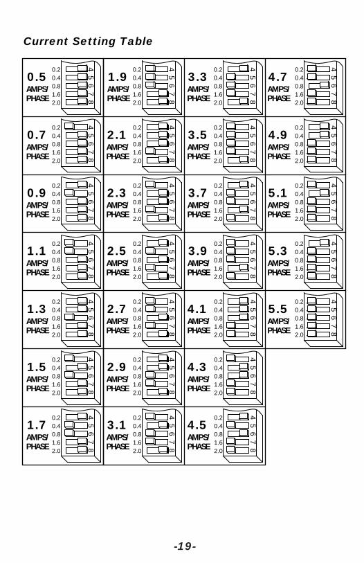
Current Setting Table
45
67
84
56
78
45
67
84
56
78
45
67
84
56
78
45
67
8
45
67
84
56
78
45
67
84
56
78
45
67
84
56
78
45
67
84
56
78
45
67
84
56
78
45
67
84
56
78
45
67
8
45
67
84
56
78
45
67
84
56
78
45
67
8
1.9AMPS/PHASE
0.20.40.81.62.0
45
67
8
-7-
Eight lead motors can also be connected in two ways: series and parallel. Aswith six lead motors, series operation gives you more torque at low speeds and lesstorque at high speeds. In series operation, the motor should be operated at 30%less than the rated current to prevent overheating. The wiring diagrams for eight leadmotors are shown below.
A+
A–
B+ B–
8lead
motor
8 Leads Series Connected 8 Leads Parallel Connected
Idle Current ReductionYour drive is equipped with a feature that automatically reduces the motor current by50% anytime the motor is not moving. This reduces drive heating by about 50%and lowers motor heating by 75%. This feature can be disabled if desired so that fullcurrent is maintained at all times. This is useful when a high holding torque isrequired. To minimize motor and drive heating we highly recommend that you usethe idle current reduction feature unless your application strictly forbids it. Idlecurrent reduction is enabled by sliding switch #3 toward the 50% IDLE label, asshown in the sketch below. Sliding the switch away from the 50% IDLE labeldisables the reduction feature.
Setting Phase CurrentBefore you turn on the power supply the first time, you need to set the driver for theproper motor phase current. The rated current is usually printed on the motor label.The current you set on the PDO 5580 is the peak current, not RMS.
The PDO 5580 drive current is easy to set. If you wish, you can learn a simpleformula for setting current and never need the manual again. Or you can skip to thetable on the next page, find the current setting you want, and set the DIP switchesaccording to the picture.
Current Setting FormulaLocate the bank of eight switches. Five of the switches have a value of currentprinted next to them, such as 0.2 and 1.6. Each switch controls the amount ofcurrent, in amperes (A), that it’s label indicates. There is always a base current of 0.5A. To add to that, slide the appropriate switches toward their labels. You may needyour small screwdriver for this.ExampleSuppose you want to set the driver for 2.9 ampsper phase. You need the 0.5 A basecurrent plus another 2.0 and 0.4 A.2.9 (TOTAL) = 0.5 (BASE) + 2.0 + 0.4Slide the 2.0 and 0.4 A switches toward the labelsas shown in the figure.
0.20.40.81.62.0
CURRENT(BASE=0.5A)
45
67
8
Idle Current Reduction Idle Current ReductionEnabled Disabled
50% IDLE 50% IDLE3 3
-8-
SELF TEST 6
OSC BYPASS 5
Pulse & Direction Mode
SELF TEST 6
Self Test Mode
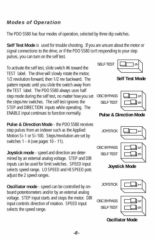
Modes of Operation
The PDO 5580 has four modes of operation, selected by three dip switches.
Self Test Mode is used for trouble shooting. If you are unsure about the motor orsignal connections to the drive, or if the PDO 5580 isn’t responding to your steppulses, you can turn on the self test.
To activate the self test, slide switch #6 toward theTEST label. The drive will slowly rotate the motor,1/2 revolution forward, then 1/2 rev backward. Thepattern repeats until you slide the switch away fromthe TEST label. The PDO 5580 always uses halfstep mode during the self test, no matter how you setthe steps/rev switches. The self test ignores theSTEP and DIRECTION inputs while operating. TheENABLE input continues to function normally.
Pulse & Direction Mode - the PDO 5580 receivesstep pulses from an indexer such as the AppliedMotion Si-1 or Si-100. Steps/revolution are set byswitches 1 - 4 (see pages 10 - 11).
Joystick mode - speed and direction are deter-mined by an external analog voltage. STEP and DIRinputs can be used for limit switches. SPEED inputselects speed range. LO SPEED and HI SPEED potsadjust the 2 speed ranges.
Oscillator mode - speed can be controlled by on-board potentiometers and/or by an external analogvoltage. STEP input starts and stops the motor. DIRinput controls direction of rotation. SPEED inputselects the speed range. SELF TEST 6
OSC BYPASS 5
Oscillator Mode
JOYSTICK 1
SELF TEST 6
OSC BYPASS 5
Joystick Mode
JOYSTICK 1
-17-
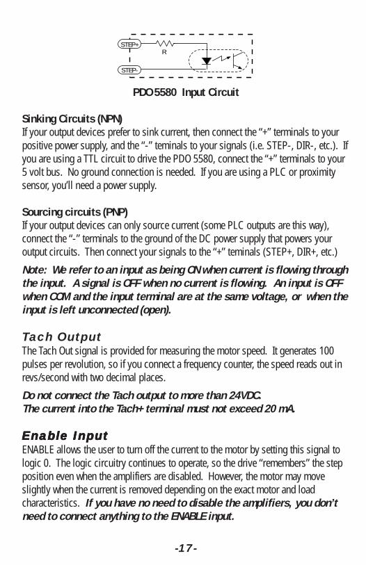
PDO 5580 Input Circuit
Sinking Circuits (NPN)If your output devices prefer to sink current, then connect the “+” terminals to yourpositive power supply, and the “-” teminals to your signals (i.e. STEP-, DIR-, etc.). Ifyou are using a TTL circuit to drive the PDO 5580, connect the “+” terminals to your5 volt bus. No ground connection is needed. If you are using a PLC or proximitysensor, you’ll need a power supply.
Sourcing circuits (PNP)If your output devices can only source current (some PLC outputs are this way),connect the “-” terminals to the ground of the DC power supply that powers youroutput circuits. Then connect your signals to the “+” teminals (STEP+, DIR+, etc.)
Note: We refer to an input as being ON when current is flowing throughthe input. A signal is OFF when no current is flowing. An input is OFFwhen COM and the input terminal are at the same voltage, or when theinput is left unconnected (open).
Tach OutputThe Tach Out signal is provided for measuring the motor speed. It generates 100pulses per revolution, so if you connect a frequency counter, the speed reads out inrevs/second with two decimal places.
Do not connect the Tach output to more than 24VDC.The current into the Tach+ terminal must not exceed 20 mA.
Enable InputEnable InputEnable InputEnable InputEnable InputENABLE allows the user to turn off the current to the motor by setting this signal tologic 0. The logic circuitry continues to operate, so the drive “remembers” the stepposition even when the amplifiers are disabled. However, the motor may moveslightly when the current is removed depending on the exact motor and loadcharacteristics. If you have no need to disable the amplifiers, you don’tneed to connect anything to the ENABLE input.
STEP-
STEP+R
-9-
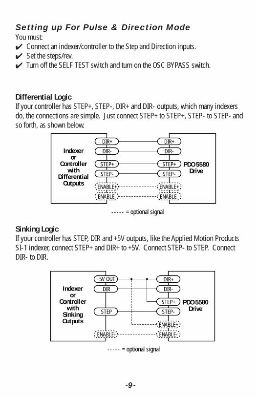
Setting up For Pulse & Direction ModeYou must: Connect an indexer/controller to the Step and Direction inputs. Set the steps/rev. Turn off the SELF TEST switch and turn on the OSC BYPASS switch.
Sinking LogicIf your controller has STEP, DIR and +5V outputs, like the Applied Motion ProductsSI-1 indexer, connect STEP+ and DIR+ to +5V. Connect STEP- to STEP. ConnectDIR- to DIR.
Differential LogicIf your controller has STEP+, STEP-, DIR+ and DIR- outputs, which many indexersdo, the connections are simple. Just connect STEP+ to STEP+, STEP- to STEP- andso forth, as shown below.
PDO 5580Drive
DIR+ DIR+
DIR- DIR-
STEP+ STEP+
STEP- STEP-
ENABLE+ ENABLE+
ENABLE- ENABLE-
Indexeror
Controllerwith
DifferentialOutputs
= optional signal
PDO 5580Drive
+5V OUT DIR+
DIR DIR-
STEP+
STEP STEP-
ENABLE+
ENABLE- ENABLE-
Indexeror
Controllerwith
SinkingOutputs
= optional signal
-16-
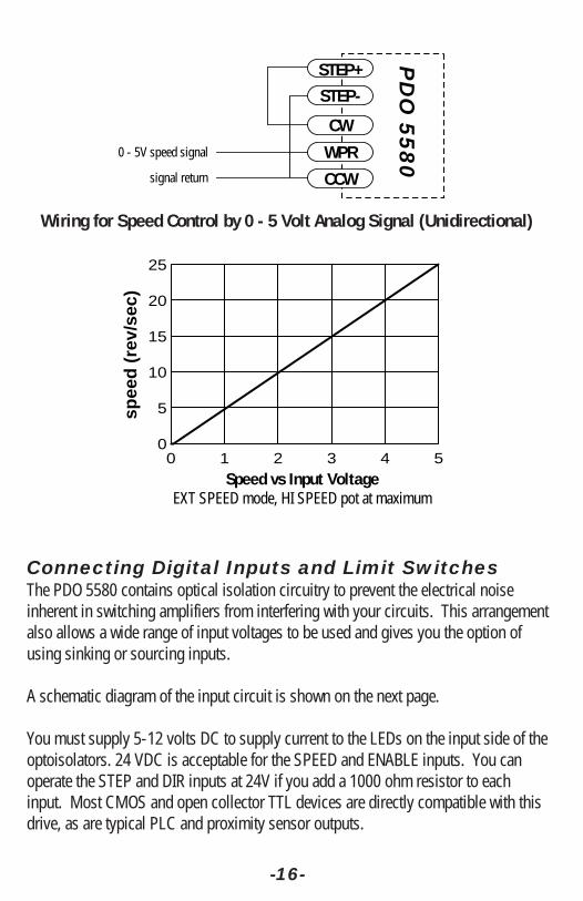
Wiring for Speed Control by 0 - 5 Volt Analog Signal (Unidirectional)
Connecting Digital Inputs and Limit SwitchesThe PDO 5580 contains optical isolation circuitry to prevent the electrical noiseinherent in switching amplifiers from interfering with your circuits. This arrangementalso allows a wide range of input voltages to be used and gives you the option ofusing sinking or sourcing inputs.
A schematic diagram of the input circuit is shown on the next page.
You must supply 5-12 volts DC to supply current to the LEDs on the input side of theoptoisolators. 24 VDC is acceptable for the SPEED and ENABLE inputs. You canoperate the STEP and DIR inputs at 24V if you add a 1000 ohm resistor to eachinput. Most CMOS and open collector TTL devices are directly compatible with thisdrive, as are typical PLC and proximity sensor outputs.
Speed vs Input VoltageEXT SPEED mode, HI SPEED pot at maximum
spee
d (r
ev/s
ec)
0 1 2 3 4 50
5
10
15
20
25
0 - 5V speed signal
signal return
PD
O 5
58
0
STEP+STEP-
CCW
WPR
CW
-10-
Sourcing LogicIf your controller has STEP, DIR and GND (ground or common) outputs, connectSTEP- and DIR- to GND. Connect STEP+ to STEP. Connect DIR+ to DIR.
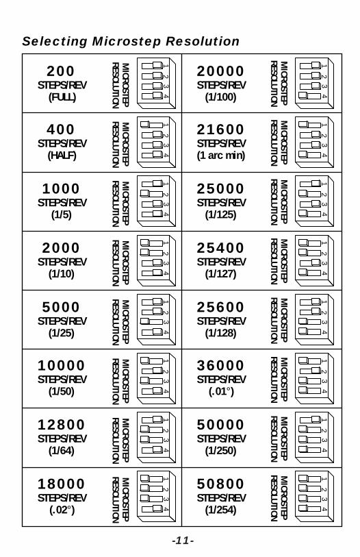
MicrosteppingMost step motor drives offer a choice between full step and half step resolutions. Infull step mode, both motor phases are used all the time. Half stepping divides eachstep into two smaller steps by alternating between both phases on and one phase on.
Microstepping drives like the PDO 5580 precisely control the amount of current ineach phase at each step position as a means of electronically subdividing the stepseven further. The PDO 5580 offers a choice of full and half step as well as 14 otherstep resolutions. The highest setting divides each full step into 254microsteps, providing 50,800 steps per revolution when using a 1.8° motor.
In addition to providing precise positioning and smooth motion, microstep drivescan be used for motion conversion between different units. The 25,400 step/revsetting is provided as a means of converting motion from metric to english. (Thereare 25.4 mm in an inch.) Other settings provide step angles that are decimaldegrees (36,000 steps/rev makes the motor take 0.01° steps.) Some settings areused with lead screws. When the drive is set to 2000 steps/rev and used with a 5pitch lead screw, you get .0001 inches/step.
PDO 5580Drive
DIR DIR+
DIR-
STEP STEP+
STEP-
ENABLE ENABLE+
GROUND ENABLE-
Indexeror
Controllerwith
SourcingOutputs
= optional signal
-15-
Typical Wiring for Oscillator Mode Using External Speed Control Pot
Speed Control from a 0 to 5 Volt Analog SignalIn oscillator mode, the PDO 5580 can rotate the motor at a speed proportional to ananalog voltage. The voltage must be applied to the WPR terminal. The direction ofrotation is controlled by the digital DIR input and the motor can be stopped either bysetting the analog input voltage to 0 or by turning the digital STEP signal off.
To use the PDO 5580 in this mode, set switch #1 away from theJOYSTICK label, and set switch #2 toward the EXT SPEED label.
The HI SPEED pot sets the maximum speed (the motor speed when the analog signalis at 5 volt DC). The range is 0 - 25 rev/sec. Wiring diagrams and a plot of speed vsvoltage are shown below and on the next page.
ext speedjoystick
Wiring for Speed Control by 0 - 5 Volt Analog Signal (with Dir Control)
5kΩpot
speed switch (closed=lo speed)
cw
ccw
PD
O 5
58
0
SPEED+
DIR-
STEP-
SPEED-
CCW
WPR
CW
DIR+STEP+
+5-12VDC
SUPPLY-
direction switch
run/stop switch(closed=run)
0 - 5V speed signal
signal return
PD
O 5
58
0
DIR+
DIR-
STEP-
CCW
WPR
STEP+
+5-12VDC
SUPPLY-
direction switch
run/stop switch(closed=run)
-11-
200STEPS/REV
(FULL)
MICROSTEP
RESOLUTIONM
ICROSTEPRESOLUTION
MICROSTEP
RESOLUTIONM
ICROSTEPRESOLUTION
MICROSTEP
RESOLUTIONM
ICROSTEPRESOLUTION
MICROSTEP
RESOLUTIONM
ICROSTEPRESOLUTION
MICROSTEP
RESOLUTIONM
ICROSTEPRESOLUTION
MICROSTEP
RESOLUTIONM
ICROSTEPRESOLUTION
MICROSTEP
RESOLUTIONM
ICROSTEPRESOLUTION
MICROSTEP
RESOLUTIONM
ICROSTEPRESOLUTION
Selecting Microstep Resolution
400STEPS/REV
(HALF)
1000STEPS/REV
(1/5)
2000STEPS/REV
(1/10)
5000STEPS/REV
(1/25)
10000STEPS/REV
(1/50)
12800STEPS/REV
(1/64)
18000STEPS/REV
(.02°)
20000STEPS/REV
(1/100)
21600STEPS/REV(1 arc min)
25000STEPS/REV
(1/125)
25400STEPS/REV
(1/127)
25600STEPS/REV
(1/128)
36000STEPS/REV
(.01°)
50000STEPS/REV
(1/250)
50800STEPS/REV
(1/254)
43
21
43
21
43
21
43
21
43
21
43
21
43
21
43
21
43
21
43
21
43
21
43
21
43
21
43
21
43
21
43
21
-14-
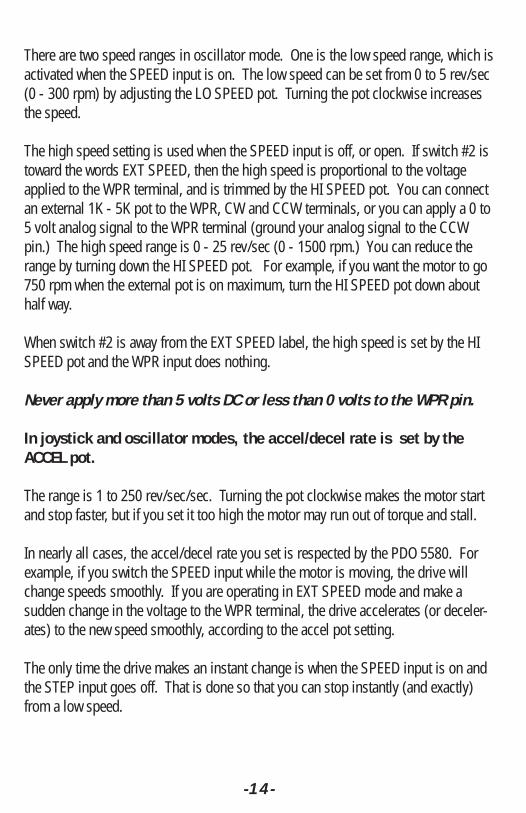
There are two speed ranges in oscillator mode. One is the low speed range, which isactivated when the SPEED input is on. The low speed can be set from 0 to 5 rev/sec(0 - 300 rpm) by adjusting the LO SPEED pot. Turning the pot clockwise increasesthe speed.
The high speed setting is used when the SPEED input is off, or open. If switch #2 istoward the words EXT SPEED, then the high speed is proportional to the voltageapplied to the WPR terminal, and is trimmed by the HI SPEED pot. You can connectan external 1K - 5K pot to the WPR, CW and CCW terminals, or you can apply a 0 to5 volt analog signal to the WPR terminal (ground your analog signal to the CCWpin.) The high speed range is 0 - 25 rev/sec (0 - 1500 rpm.) You can reduce therange by turning down the HI SPEED pot. For example, if you want the motor to go750 rpm when the external pot is on maximum, turn the HI SPEED pot down abouthalf way.
When switch #2 is away from the EXT SPEED label, the high speed is set by the HISPEED pot and the WPR input does nothing.
Never apply more than 5 volts DC or less than 0 volts to the WPR pin.
In joystick and oscillator modes, the accel/decel rate is set by theACCEL pot.
The range is 1 to 250 rev/sec/sec. Turning the pot clockwise makes the motor startand stop faster, but if you set it too high the motor may run out of torque and stall.
In nearly all cases, the accel/decel rate you set is respected by the PDO 5580. Forexample, if you switch the SPEED input while the motor is moving, the drive willchange speeds smoothly. If you are operating in EXT SPEED mode and make asudden change in the voltage to the WPR terminal, the drive accelerates (or deceler-ates) to the new speed smoothly, according to the accel pot setting.
The only time the drive makes an instant change is when the SPEED input is on andthe STEP input goes off. That is done so that you can stop instantly (and exactly)from a low speed.
-12-
Joystick ModeIn this mode, speed and direction are determined by the voltage applied to the WPR(wiper) terminal. 2.5 volts is “stopped” (no speed). Increasing the WPR voltagetoward 5 volts results in forward motion: speed increases with voltage. Decreasingthe WPR voltage from 2.5 toward 0 results in reverse motion, with speed increasingas voltage decreases. In joystick mode, the PDO 5580 operates at 12800 steps/rev.
The maximum speed is determined by two things: the state of the SPEED input andthe HI SPEED and LO SPEED trimpots. When the SPEED input is ON, the speedrange of the joystick can be adjusted with the LO SPEED pot, up to 5 rev/sec (300rpm) When the SPEED input is OFF (or open), the joystick speed range is adjustedwith the HI SPEED pot, up to 25 rev/sec (1500 rpm). Turning the pots clockwiseincreases the speed.
In joystick mode, limit switches can be connected to the PDO 5580 to preventmotion outside of defined limits. The forward limit should be connected to the STEPinput and the reverse limit should be connected to the DIR input. When the forwardlimit is ON, the motor will not move forward (that is, when the joystick voltage isbetween 2.5 and 5 volts.) When the reverse limit is ON, the motor will not movewhen the joystick is in the 0 to 2.5 volt range. If you don’t need limits, you can leavethe STEP and DIR inputs unconnected.
5kΩjoystick
joystick "fire" button
fwd
rev
PD
O 5
58
0
SPEED+
DIR-
STEP-
SPEED-
CCW
WPR
CW
+5-12VDC
SUPPLY-
DIR+
STEP+
rev limit switch
fwd limit switch
-13-
Oscillator ModeIn oscillator mode, the PDO 5580 uses the direction set by the DIR input. Off, oropen, gives clockwise motion, if the motor is wired according to pages 6 and 7.Motor speed and the function of the STEP input can be determined from the follow-ing table. In oscillator mode, the PDO 5580 operates at 12800 steps/rev.
Speed vs Input VoltageJoystick Mode, SPEED input off (open)
HI SPEED pot at maximum
0 1 2 3 4 5-25-20-15-10
-505
10152025
volts volts
spee
d (r
ev/s
ec)
SPEED switches speed set when STEP when STEPinput 1 & 2 by goes ON goes OFF
ON accel to speed instant stop
ON accel to speed instant stop
OFF/open accel to speed decel to stop
OFF/open accel to speed decel to stop
ext speedjoystick
ext speedjoystick
ext speedjoystick
ext speedjoystick
LO SPEED
LO SPEED
HI SPEED
HI SPEED
WPR inputtrimmed by
-11-
200STEPS/REV
(FULL)
MICROSTEP
RESOLUTIONM
ICROSTEPRESOLUTION
MICROSTEP
RESOLUTIONM
ICROSTEPRESOLUTION
MICROSTEP
RESOLUTIONM
ICROSTEPRESOLUTION
MICROSTEP
RESOLUTIONM
ICROSTEPRESOLUTION
MICROSTEP
RESOLUTIONM
ICROSTEPRESOLUTION
MICROSTEP
RESOLUTIONM
ICROSTEPRESOLUTION
MICROSTEP
RESOLUTIONM
ICROSTEPRESOLUTION
MICROSTEP
RESOLUTIONM
ICROSTEPRESOLUTION
Selecting Microstep Resolution
400STEPS/REV
(HALF)
1000STEPS/REV
(1/5)
2000STEPS/REV
(1/10)
5000STEPS/REV
(1/25)
10000STEPS/REV
(1/50)
12800STEPS/REV
(1/64)
18000STEPS/REV
(.02°)
20000STEPS/REV
(1/100)
21600STEPS/REV(1 arc min)
25000STEPS/REV
(1/125)
25400STEPS/REV
(1/127)
25600STEPS/REV
(1/128)
36000STEPS/REV
(.01°)
50000STEPS/REV
(1/250)
50800STEPS/REV
(1/254)
43
21
43
21
43
21
43
21
43
21
43
21
43
21
43
21
43
21
43
21
43
21
43
21
43
21
43
21
43
21
43
21
-14-
There are two speed ranges in oscillator mode. One is the low speed range, which isactivated when the SPEED input is on. The low speed can be set from 0 to 5 rev/sec(0 - 300 rpm) by adjusting the LO SPEED pot. Turning the pot clockwise increasesthe speed.
The high speed setting is used when the SPEED input is off, or open. If switch #2 istoward the words EXT SPEED, then the high speed is proportional to the voltageapplied to the WPR terminal, and is trimmed by the HI SPEED pot. You can connectan external 1K - 5K pot to the WPR, CW and CCW terminals, or you can apply a 0 to5 volt analog signal to the WPR terminal (ground your analog signal to the CCWpin.) The high speed range is 0 - 25 rev/sec (0 - 1500 rpm.) You can reduce therange by turning down the HI SPEED pot. For example, if you want the motor to go750 rpm when the external pot is on maximum, turn the HI SPEED pot down abouthalf way.
When switch #2 is away from the EXT SPEED label, the high speed is set by the HISPEED pot and the WPR input does nothing.
Never apply more than 5 volts DC or less than 0 volts to the WPR pin.
In joystick and oscillator modes, the accel/decel rate is set by theACCEL pot.
The range is 1 to 250 rev/sec/sec. Turning the pot clockwise makes the motor startand stop faster, but if you set it too high the motor may run out of torque and stall.
In nearly all cases, the accel/decel rate you set is respected by the PDO 5580. Forexample, if you switch the SPEED input while the motor is moving, the drive willchange speeds smoothly. If you are operating in EXT SPEED mode and make asudden change in the voltage to the WPR terminal, the drive accelerates (or deceler-ates) to the new speed smoothly, according to the accel pot setting.
The only time the drive makes an instant change is when the SPEED input is on andthe STEP input goes off. That is done so that you can stop instantly (and exactly)from a low speed.
-10-
Sourcing LogicIf your controller has STEP, DIR and GND (ground or common) outputs, connectSTEP- and DIR- to GND. Connect STEP+ to STEP. Connect DIR+ to DIR.
MicrosteppingMost step motor drives offer a choice between full step and half step resolutions. Infull step mode, both motor phases are used all the time. Half stepping divides eachstep into two smaller steps by alternating between both phases on and one phase on.
Microstepping drives like the PDO 5580 precisely control the amount of current ineach phase at each step position as a means of electronically subdividing the stepseven further. The PDO 5580 offers a choice of full and half step as well as 14 otherstep resolutions. The highest setting divides each full step into 254microsteps, providing 50,800 steps per revolution when using a 1.8° motor.
In addition to providing precise positioning and smooth motion, microstep drivescan be used for motion conversion between different units. The 25,400 step/revsetting is provided as a means of converting motion from metric to english. (Thereare 25.4 mm in an inch.) Other settings provide step angles that are decimaldegrees (36,000 steps/rev makes the motor take 0.01° steps.) Some settings areused with lead screws. When the drive is set to 2000 steps/rev and used with a 5pitch lead screw, you get .0001 inches/step.
PDO 5580Drive
DIR DIR+
DIR-
STEP STEP+
STEP-
ENABLE ENABLE+
GROUND ENABLE-
Indexeror
Controllerwith
SourcingOutputs
= optional signal
-15-
Typical Wiring for Oscillator Mode Using External Speed Control Pot
Speed Control from a 0 to 5 Volt Analog SignalIn oscillator mode, the PDO 5580 can rotate the motor at a speed proportional to ananalog voltage. The voltage must be applied to the WPR terminal. The direction ofrotation is controlled by the digital DIR input and the motor can be stopped either bysetting the analog input voltage to 0 or by turning the digital STEP signal off.
To use the PDO 5580 in this mode, set switch #1 away from theJOYSTICK label, and set switch #2 toward the EXT SPEED label.
The HI SPEED pot sets the maximum speed (the motor speed when the analog signalis at 5 volt DC). The range is 0 - 25 rev/sec. Wiring diagrams and a plot of speed vsvoltage are shown below and on the next page.
ext speedjoystick
Wiring for Speed Control by 0 - 5 Volt Analog Signal (with Dir Control)
5kΩpot
speed switch (closed=lo speed)
cw
ccw
PD
O 5
58
0
SPEED+
DIR-
STEP-
SPEED-
CCW
WPR
CW
DIR+STEP+
+5-12VDC
SUPPLY-
direction switch
run/stop switch(closed=run)
0 - 5V speed signal
signal return
PD
O 5
58
0
DIR+
DIR-
STEP-
CCW
WPR
STEP+
+5-12VDC
SUPPLY-
direction switch
run/stop switch(closed=run)
-9-
Setting up For Pulse & Direction ModeYou must: Connect an indexer/controller to the Step and Direction inputs. Set the steps/rev. Turn off the SELF TEST switch and turn on the OSC BYPASS switch.
Sinking LogicIf your controller has STEP, DIR and +5V outputs, like the Applied Motion ProductsSI-1 indexer, connect STEP+ and DIR+ to +5V. Connect STEP- to STEP. ConnectDIR- to DIR.
Differential LogicIf your controller has STEP+, STEP-, DIR+ and DIR- outputs, which many indexersdo, the connections are simple. Just connect STEP+ to STEP+, STEP- to STEP- andso forth, as shown below.
PDO 5580Drive
DIR+ DIR+
DIR- DIR-
STEP+ STEP+
STEP- STEP-
ENABLE+ ENABLE+
ENABLE- ENABLE-
Indexeror
Controllerwith
DifferentialOutputs
= optional signal
PDO 5580Drive
+5V OUT DIR+
DIR DIR-
STEP+
STEP STEP-
ENABLE+
ENABLE- ENABLE-
Indexeror
Controllerwith
SinkingOutputs
= optional signal
-16-
Wiring for Speed Control by 0 - 5 Volt Analog Signal (Unidirectional)
Connecting Digital Inputs and Limit SwitchesThe PDO 5580 contains optical isolation circuitry to prevent the electrical noiseinherent in switching amplifiers from interfering with your circuits. This arrangementalso allows a wide range of input voltages to be used and gives you the option ofusing sinking or sourcing inputs.
A schematic diagram of the input circuit is shown on the next page.
You must supply 5-12 volts DC to supply current to the LEDs on the input side of theoptoisolators. 24 VDC is acceptable for the SPEED and ENABLE inputs. You canoperate the STEP and DIR inputs at 24V if you add a 1000 ohm resistor to eachinput. Most CMOS and open collector TTL devices are directly compatible with thisdrive, as are typical PLC and proximity sensor outputs.
Speed vs Input VoltageEXT SPEED mode, HI SPEED pot at maximum
spee
d (r
ev/s
ec)
0 1 2 3 4 50
5
10
15
20
25
0 - 5V speed signal
signal returnP
DO
55
80
STEP+STEP-
CCW
WPR
CW
-8-
SELF TEST 6
OSC BYPASS 5
Pulse & Direction Mode
SELF TEST 6
Self Test Mode
Modes of Operation
The PDO 5580 has four modes of operation, selected by three dip switches.
Self Test Mode is used for trouble shooting. If you are unsure about the motor orsignal connections to the drive, or if the PDO 5580 isn’t responding to your steppulses, you can turn on the self test.
To activate the self test, slide switch #6 toward theTEST label. The drive will slowly rotate the motor,1/2 revolution forward, then 1/2 rev backward. Thepattern repeats until you slide the switch away fromthe TEST label. The PDO 5580 always uses halfstep mode during the self test, no matter how you setthe steps/rev switches. The self test ignores theSTEP and DIRECTION inputs while operating. TheENABLE input continues to function normally.
Pulse & Direction Mode - the PDO 5580 receivesstep pulses from an indexer such as the AppliedMotion Si-1 or Si-100. Steps/revolution are set byswitches 1 - 4 (see pages 10 - 11).
Joystick mode - speed and direction are deter-mined by an external analog voltage. STEP and DIRinputs can be used for limit switches. SPEED inputselects speed range. LO SPEED and HI SPEED potsadjust the 2 speed ranges.
Oscillator mode - speed can be controlled by on-board potentiometers and/or by an external analogvoltage. STEP input starts and stops the motor. DIRinput controls direction of rotation. SPEED inputselects the speed range. SELF TEST 6
OSC BYPASS 5
Oscillator Mode
JOYSTICK 1
SELF TEST 6
OSC BYPASS 5Joystick Mode
JOYSTICK 1
-17-
PDO 5580 Input Circuit
Sinking Circuits (NPN)If your output devices prefer to sink current, then connect the “+” terminals to yourpositive power supply, and the “-” teminals to your signals (i.e. STEP-, DIR-, etc.). Ifyou are using a TTL circuit to drive the PDO 5580, connect the “+” terminals to your5 volt bus. No ground connection is needed. If you are using a PLC or proximitysensor, you’ll need a power supply.
Sourcing circuits (PNP)If your output devices can only source current (some PLC outputs are this way),connect the “-” terminals to the ground of the DC power supply that powers youroutput circuits. Then connect your signals to the “+” teminals (STEP+, DIR+, etc.)
Note: We refer to an input as being ON when current is flowing throughthe input. A signal is OFF when no current is flowing. An input is OFFwhen COM and the input terminal are at the same voltage, or when theinput is left unconnected (open).
Tach OutputThe Tach Out signal is provided for measuring the motor speed. It generates 100pulses per revolution, so if you connect a frequency counter, the speed reads out inrevs/second with two decimal places.
Do not connect the Tach output to more than 24VDC.The current into the Tach+ terminal must not exceed 20 mA.
Enable InputEnable InputEnable InputEnable InputEnable InputENABLE allows the user to turn off the current to the motor by setting this signal tologic 0. The logic circuitry continues to operate, so the drive “remembers” the stepposition even when the amplifiers are disabled. However, the motor may moveslightly when the current is removed depending on the exact motor and loadcharacteristics. If you have no need to disable the amplifiers, you don’tneed to connect anything to the ENABLE input.
STEP-
STEP+R
-7-
Eight lead motors can also be connected in two ways: series and parallel. Aswith six lead motors, series operation gives you more torque at low speeds and lesstorque at high speeds. In series operation, the motor should be operated at 30%less than the rated current to prevent overheating. The wiring diagrams for eight leadmotors are shown below.
A+
A–
B+ B–
8lead
motor
8 Leads Series Connected 8 Leads Parallel Connected
Idle Current ReductionYour drive is equipped with a feature that automatically reduces the motor current by50% anytime the motor is not moving. This reduces drive heating by about 50%and lowers motor heating by 75%. This feature can be disabled if desired so that fullcurrent is maintained at all times. This is useful when a high holding torque isrequired. To minimize motor and drive heating we highly recommend that you usethe idle current reduction feature unless your application strictly forbids it. Idlecurrent reduction is enabled by sliding switch #3 toward the 50% IDLE label, asshown in the sketch below. Sliding the switch away from the 50% IDLE labeldisables the reduction feature.
Setting Phase CurrentBefore you turn on the power supply the first time, you need to set the driver for theproper motor phase current. The rated current is usually printed on the motor label.The current you set on the PDO 5580 is the peak current, not RMS.
The PDO 5580 drive current is easy to set. If you wish, you can learn a simpleformula for setting current and never need the manual again. Or you can skip to thetable on the next page, find the current setting you want, and set the DIP switchesaccording to the picture.
Current Setting FormulaLocate the bank of eight switches. Five of the switches have a value of currentprinted next to them, such as 0.2 and 1.6. Each switch controls the amount ofcurrent, in amperes (A), that it’s label indicates. There is always a base current of 0.5A. To add to that, slide the appropriate switches toward their labels. You may needyour small screwdriver for this.ExampleSuppose you want to set the driver for 2.9 ampsper phase. You need the 0.5 A basecurrent plus another 2.0 and 0.4 A.2.9 (TOTAL) = 0.5 (BASE) + 2.0 + 0.4Slide the 2.0 and 0.4 A switches toward the labelsas shown in the figure.
0.20.40.81.62.0
CURRENT(BASE=0.5A)
45
67
8
Idle Current Reduction Idle Current ReductionEnabled Disabled
50% IDLE 50% IDLE3 3
-6-
A+
A–
NC
B+B– NC
6leadmotor
RedBlack
Red/Wht
Green
Grn/Wht
White A+
A–
NC
B+B– NC
6lead
motor
Grn/Wht
White
Green
RedRed/Wht
Black
6 Leads Series Connected 6 Leads Center Tap Connected
A+
A–
B+ B–
4lead
motor
Red
Blue
Yellow White
4 Leads
!
Connecting the Motor
Never connect the motor to the driver when the AC power is on.Secure any unused motor leads.Never disconnect the motor while the AC power is on.Never connect motor leads to ground or to a power supply.
You must now decide how to connect yourmotor to the drive.
Four lead motors can only be connectedone way. Please follow the sketch at the right.
Six lead motors can be connected in series or center tap. In series mode, motorsproduce more torque at low speeds, but cannot run as fast as in the center tapconfiguration. In series operation, the motor should be operated at 30% less thanthe rated current to prevent overheating. Wiring diagrams for both connectionmethods are shown below.
Note: NC means not connected to anything.
-19-
0.5AMPS/PHASE
0.20.40.81.62.0
0.7AMPS/PHASE
0.20.40.81.62.0
0.9AMPS/PHASE
0.20.40.81.62.0
1.1AMPS/PHASE
0.20.40.81.62.0
1.3AMPS/PHASE
0.20.40.81.62.0
1.5AMPS/PHASE
0.20.40.81.62.0
1.7AMPS/PHASE
0.20.40.81.62.0
2.1AMPS/PHASE
0.20.40.81.62.0
2.3AMPS/PHASE
0.20.40.81.62.0
2.5AMPS/PHASE
0.20.40.81.62.0
2.7AMPS/PHASE
0.20.40.81.62.0
2.9AMPS/PHASE
0.20.40.81.62.0
3.1AMPS/PHASE
0.20.40.81.62.0
3.3AMPS/PHASE
0.20.40.81.62.0
3.5AMPS/PHASE
0.20.40.81.62.0
3.7AMPS/PHASE
0.20.40.81.62.0
3.9AMPS/PHASE
AMPS/PHASE
AMPS/PHASE
AMPS/PHASE
0.20.40.81.62.0
4.10.20.40.81.62.0
4.30.20.40.81.62.0
4.50.20.40.81.62.0
4.70.20.40.81.62.0
4.90.20.40.81.62.0
5.10.20.40.81.62.0
5.3AMPS/PHASE
AMPS/PHASE
AMPS/PHASE
AMPS/PHASE
0.20.40.81.62.0
5.5AMPS/PHASE
0.20.40.81.62.0
Current Setting Table
45
67
84
56
78
45
67
84
56
78
45
67
84
56
78
45
67
8
45
67
84
56
78
45
67
84
56
78
45
67
84
56
78
45
67
84
56
78
45
67
84
56
78
45
67
84
56
78
45
67
8
45
67
84
56
78
45
67
84
56
78
45
67
8
1.9AMPS/PHASE
0.20.40.81.62.0
45
67
8
-5-
Installing an AC Line CordRemove about 5 mm (3/16 inches) of insulation from each of the three wires of yourline cord. (That’s right, three wires. For safety, always use a three wire power cordon anything with a metal case.) Depending on where you got your power cord, itmay have black, white and green wires or brown/blue/green.
The AC power plug that was shipped with your PDO 5580 might be one of two types.The “old style” is shown below, on the left. The “new style” (shown on the right)comes with an insulating rubber boot.
Make sure you follow the proper sketch your connector style.
•Connect the black or brown wire to the PDO 5580 “L” terminal of the AC powerconnector. That is the line, or “hot” connection.•Connect the white or blue wire to neutral. That’s the “N” terminal.•Finally, and most importantly, connect the green wire to the GND terminal. Thatconnects the PDO 5580 metal enclosure and DC power supply ground to earthground.
!
kcalbetihwneerg
To Earth Ground
To Neutral
To Line (Hot)
To Earth Ground
To Neutral
To Line (Hot)
green
black or brown
whit e or blue
"Old Style" AC Power Plug
"New Style" AC Power Plug
B–B+A–A+
GNDNL
switch in 110V positionfuse
B–B+A–A+
GNDNL
switch in 220V positionfuse
Always unplug the line cord from the wall before attaching itto the PDO 5580 O
-20-
Fault Protection
The PDO 5580 provides protection against motor short circuits and excessive drivetemperature.
If the TEMP light is on, the PDO 5580 has detected a thermal problem and shut downthe amplifiers. The first thing you should do is to unplug the drive from the powersource. Next, touch the heat sink with your fingers. If it is very hot, the drive hasprobably overheated. Usually this means you need more air flow around the drive.
If the SHORT light is on, the PDO 5580 has detected a short circuit and has shutdown the amplifiers. Unplug the drive from the power source. Check the motorwiring carefully. Make sure that the connections to the drive are secure and that anyunused motor leads are insulated from the drive and power supply and from eachother. Check the motor leads for shorts between phases or to ground.
Using the Fault OutputThe PD5580 has a fault output to tell another device (such as a PLC) if the drive hasoverheats or encounters a short circuit has occured at the motor outputs. The faultoutput is optically isolated for noise immunity. This makes it more flexible and morereliable, but also requires a 5, 12 or 24 VDC power source to hook it up. To connectto typical PLC, follow the sketch below.
The photo transistor turns on (closes) when there is a fault.
24 VDCPowerSupply
PD
O 5
580
FAULT-
PLC
FAULT+OUT
COM
-+
-4-
Before you can change the 110/220 volt switch setting, you must remove the motorconnector and the AC power connector from the drive. Set the drive on the widestside, so that the heat sink fins are pointing upward.
Once you’ve done that, you’ll see an opening in the case, just above the threeposition and four position green connectors.
If you look into the slot, you should see two black objects. The one on the left is thefuse. The black object to the right of the fuse is the 110/220 volt switch. Thesketches below and on page 5 show the two positions of the switch. To change from110V to 220V, carefully insert your screwdriver into the slot and push the switch tothe right.
Connecting the AC Line110 VoltsThe PDO 5580 is set for 110 volt operation at the factory. All you need to do isinstall a power cord and plug it in. If you want to direct wire the PDO 5580 to ACpower, you must consult a qualified electrician and observe all building and electri-cal codes.
The AC cord you can install yourself, but be careful: AC power can be dangerous.
220 VoltsThe PDO 5580 is set for 110 volt operation at the factory. In order to use 220 volts,you’ll need to change a switch setting inside the case. However, you can do thisfrom outside the case with your Applied Motion screwdriver.
B–B+A–A+
MOTORGNDNL
AC POWER
Unplug these connectorsP
DO
55
80
Ste
p M
oto
r Drive
r
-21-
Recommended MotorsThe following tables lists motors and current settings that are recommended for thePDO 5580 drive.
Motor Winding Max Torque Max Power Current SettingNumber Connection oz-in Watts Amps/phase5023-122 parallel 75 60 2.05023-123 parallel 120 93 2.55023-124 parallel 177 110 3.55034-348 parallel 185 133 4.85034-349 parallel 300 151 5.05034-350 parallel 390 213 5.55042-022 parallel 595 300 5.5
Never use your drive in a space where there is no air flowor where the ambient temperature exceeds 50°C (120°F).Never block the fins of the heat sink or the vent holes.Never put the drive where it can get wet.Never allow metal particles near the drive.
!
Bracket position forwide side mounting.Place brackets ontop and bottom of
drive.
Bracketposition
for narrowside
mounting.Place
bracketson top
andbottom of
drive.
This screw is already inthe drive.
Mounting the DriveYou can mount your drive on the wide or the narrow side of the case. Either wayyou’ll need to get the brackets and screws out of the accessory bag and bolt themonto the PDO 5580. If you’re mounting on the narrow side, you’ll first have toremove one of the screws from the heat sink, then put it back with the bracket inplace, as shown in the figure.
-3-
Getting StartedTo use your Applied Motion Products motor control, you will need: a power cable (line cord) a compatible step motor (see page 21) a small flat blade screwdriver for tightening the connectors - an Applied MotionProducts screwdriver suitable for this purpose is included with your drive.For pulse & direction mode: a source of step pulses (usually an indexer is used)For oscillator mode: an instrument for measuring motor speed (tachometer, freq. counter or o-scope)For joystick mode: An analog joystick
The sketch below shows where to find the important connection and adjustmentpoints. Please examine it now.All mating connectors are included.
Dual, MOSFET H-bridge, 3 state, pulse width modulated switchingat 20 kHz. 0.5 - 5.5 amps/phase output current, switchselectable in 0.2 increments. Overcurrent and overtemperatureprotection. Automatic idle current reduction (defeatable), reducescurrent to 50% of setting after one second. Minimum motorinductance is 0.8 mH.
Linear, toroidal transformer based for high reliability and lownoise. 110 or 220 VAC input, switch selectable. 50-60 Hz.DC voltage at nominal line voltage: 75 VDC full load, 90 VDC noload.
Wiper: 0 - 5 VDC analog signal. Max recommended pot/joystickimpedance: 1K - 5K ohms. Joystick dead zone: ± 80 mV.Potentiometer/analog signal dead zone: 40 mV.
In pulse & direction mode, motor steps on falling edge of stepinput. 0.25 µsec minimum pulse, 2 MHz max step rate. 1 µsecminimum set up time, 50µs minimum hold time for directionsignal.
Tach & Fault: Optically isolated, uncommitted (open collector,open emitter) photo transistors. 30V, 20 mA max. Tach output is100 pulses per motor revolution, 50% duty cycle (square wave).
IntroductionThank you for selecting an Applied Motion Products motor control. We hope ourdedication to performance, quality and economy will make your motion controlproject successful. If there’s anything we can do to improve our products or help youuse them better, please call or fax. We’d like to hear from you. Our phone number is(800) 525-1609 or you can reach us by fax at (831) 761–6544.
Features
• Digital oscillator provides smooth accel/decel ramps and precise speed control.• Powerful microstepping amplifier provides high torque and smooth, quiet motion.• Accepts a wide range of motors: NEMA sizes 14 - 42, 0.5 to 5.5 amps/phase.• Easy to configure with on-board switches and potentiometers for all settings.• Automatic idle current reduction reduces motor and drive heating, saves power.• Pluggable screw terminal connectors make wiring easy.• Oscillator Mode operates from internal pots, external pots, 0 - 5 V analog signal,
or analog joystick.• Two speed ranges, can be selected “on the fly” by a digital signal with automatic
ramping between speeds.• Inputs and outputs are optically isolated, differential (sourcing or sinking). Speed
& Enable 5 - 24V, Step & Direction 5 - 12V.• Tach Out signal allows easy measurement of speed.• Enable input allows motor current to be shut off on command.• Built in 80 volt power supply (accepts 110 or 220 VAC power, 50-60 Hz)• MOSFET pulse width modulation switching amplifiers (3 state)• Microstepping pulse & direction mode with 16 step/rev settings from 200 (full
step) through 50,800.• Overtemp and overcurrent (short circuit) and surge protection• Built-in self test for troubleshooting.• CE and TUV compliant.
-23-
Technical Specifications (continued)
RecommendedJoystick
Speed Ranges
Physical
Connectors
CE Mark
Maurey Instrument Corp., Chicago, IL (773)581-4555JS31462S5T3 (2 axis) or SAJ2515-F-502 (1 axis)
LO speed range: 0 - 5 rev/secHI speed range: 0 - 25 rev/secAccel/decel range: 1 to 250 rev/sec/sec
Constructed with black anodized aluminum heat sink and heavygauge steel housing. 3 x 5.3 x 8 inches overall. 7.8 lbs. Ambienttemperature range: 0 - 70 C. Power, temp and motor short circuitLEDs. Mounting brackets and switch cover included. See backcover for detailed drawing .