86
User’s Manual & Quick Reference Guide GlideScope ® GVL ® and Cobalt 0900-1204-02-20
User’s Manual & Quick Reference Guide
GlideScope® GVL® and Cobalt
0900-1204-02-20


GlideScope® GVL® and Cobalt
Quick Reference Guide

Corporate Headquarters: Verathon Inc. 20001 North Creek Parkway, Bothell, WA 98011 USA 800.331.2313 (Canada and US) 425.867.1348 Fax: 425.883.2896 http://www.verathon.com
Verathon Medical (Europe) B.V. Boerhaaveweg 1 3401 MN IJsselstein The Netherlands +31.30.68.70.570 Fax: +31.30.68.70.512 http://www.verathon.eu
Verathon Medical (Canada) ULC4224 Manor Street Burnaby, BC V5G 1B2 Canada 604.439.3009 Fax: 604.439.3039
For additional contact information please visit our corporate website: http://www.verathon.com.
GlideScope®, GVL®, GlideRite®, Verathon® and Verathon Medical® are either trademarks or registered trademarks of Verathon® Inc. in the US and/or other countries.
Cidex® is a registered trademark of Advanced Sterilization Products, a Johnson & Johnson Company.
Manu-Klenz® is a registered trademark of Steris Corporation.
MetriCide® is a registered trademark of Suborn Dental Specialties, Inc.
Sterrad® is a registered trademark of Johnson & Johnson Gateway, LLC.
The GlideScope® technology is covered under US Patents (6,655,377) (6,543,447) (6,142,144) as well as European Patent 1307131. Additional patents pending.
Information in this User’s Manual may change at any time without notice. For the latest version of this manual, refer to www.verathon.com.
Copyright © 2008 by Verathon Inc. All rights reserved. No part of this manual may be copied or transmitted by any method without the express written consent of Verathon Inc.
PN 0900-2100-00-20

GlideScopeGlideScope® System Quick Start System Quick Start
The monitor may be used immediately by plugging it into an AC power source, or by fully charging the battery prior to fi rst use.
To ensure proper charging, follow these steps in order:
Make sure the AC power cord is • disconnected and the power switch is in the OFF position.
Slide the power switch at the back of the monitor to the ON position.•
Plug the Monitor into an AC power source: •
◦ Insert the female end of the power cord into the port on the back of the Monitor.
The charge status LED will turn orange, indicating that the recharging • cycle has begun.
When charging is complete, the status LED will turn green. At this • point the unit is fully functional on battery power.
If the AC power cord is inserted before the power switch is in the ON position, the charge status LED will fl ash orange.
Connect the Video Laryngoscope to the monitor.
If using the GVL• ®:Connect either end of the video cable to the GVL® connector. Connect the video cable to the monitor connector.

Corporate Headquarters:Verathon Inc.20001 North Creek ParkwayBothell, WA 98011, USATel: 800.331.2313 (US and Canada only)Tel: 425.867.1348 Fax: 425.883.2896
Manufacturer:Verathon Medical (Canada) ULC4224 Manor StreetBurnaby, British ColumbiaCanada, V5G 1B2
EC Representative:Verathon Medical (Europe) B.V.Boerhaaveweg 13401 MN lJsselstein NetherlandsTel: +31.30.68.70.570Fax: +31.30.68.70.512t
GlideScopeGlideScope® System Quick Start System Quick Start
If using the Cobalt system:• Connect the video baton to the monitor as shown for the GVL® above. Then slide a single-use GVL® Stat over the video baton.
To detach a GVL® Stat from a Cobalt Video Baton, grasp the base of the video baton and pull fi rmly.
LED State MeaningSteady green
CHARGESTATUS
The battery is fully charged and ready for use.
Flashing orange Flashing orange can indicate two states:If the AC power is connected and the power • switch is off ("O" - to the left), the CHARGE STATUS LED will fl ash orange. The monitor will still function but the battery will not charge.If the AC power is NOT connected and the • CHARGE STATUS LED fl ashes orange, the battery is malfunctioning.
Steady orange Charging in progress
www.verathon.com
0900-2077-00-60
IMPORTANT! A used GVL® Stat is a biohazard and should be disposed of in compliance with local protocols.
GlideScope®, GVL®, Verathon® and Verathon Medical® are registered trademarks of Verathon Inc. in the United States and/or other countries. All rights reserved. Copyright © 2008 by Verathon Inc. GlideScope® video laryngoscope systems are CE marked in accordance with the Medical Device Directive, and the Verathon Inc. quality system is Quality System Certifi ed to ISO 13485:2003 standards.
STAT Video Baton
CHARGESTATUS
CHARGESTATUS

Cleaning the GlideScopeCleaning the GlideScope® GVL GVL® and Cobalt Video Batonand Cobalt Video Baton
DO NOT AUTOCLAVE or expose to temperatures above 140• oF (60oC).Do not use ultrasonic pasteurization or autoclaving methods when cleaning.
The GlideScope• ® GVL® is a reusable product and must be disinfected after each use. Cobalt Video Batons may be cleaned with an isopropyl alcohol wipe between uses, or disinfected as needed.
Disconnect the GVL® or Video Baton from the monitor.
Place the cleaning cap over the connector as shown.During cleaning, the prot• ective cap must be
inserted as shown to protect the cable connector.
Wash the GVL® or Video Baton manually to remove all foreign material from the surface of the device.
Verathon• ® approves the use of the following high-level disinfectants on GlideScope® GVL® and Video Baton products: Steris System 1®, Sterrad®, Cidex®, and MetriCide®.
Verathon• ® recommends that all other components of the GlideScope® system be cleaned with alcohol wipes or a hospital grade surface cleaning product.
For more detailed cleaning instructions see the GlideScope® System User’s Manual.
GlideScope® Cobalt Cleaning Cap
GVL® Cobalt
GlideScope® Cobalt Cleaning Cap
Correct Cleaning Position

Corporate Headquarters:Verathon Inc.20001 North Creek ParkwayBothell, WA 98011, USATel: 800.331.2313 (US and Canada only)Tel: 425.867.1348 Fax: 425.883.2896
Manufacturer:Verathon Medical (Canada) ULC4224 Manor StreetBurnaby, British ColumbiaCanada, V5G 1B2
EC Representative:Verathon Medical (Europe) B.V.Boerhaaveweg 13401 MN lJsselstein NetherlandsTel: +31.30.68.70.570Fax: +31.30.68.70.512t
Attaching/Detaching the GlideScopeAttaching/Detaching the GlideScope® GVLGVL® or Cobalt Video Baton or Cobalt Video Baton
Insert the GVL® or Cobalt Video Baton cable into the port located on the face of the monitor so that the arrows on the cable and the monitor line up.
For GVL® only: Attach the opposite end of thevideo cable to the port located on the GVL®.
Note: When connecting and disconnecting the cable,grasp the connector by the gray sleeve.
Insert the Cobalt Video Baton into the sterile,single use GVL® Stat until it clicks into place. Ensure proper insertion by matching the GlideScope® logo on the side of the Video Baton and the GVL® Stat.
Detach the Video Baton from the GVL® Stat by grasping the base of the Video Baton and pulling fi rmly.
Attaching/Detaching the Attaching/Detaching the Cobalt Video Baton and StatCobalt Video Baton and Stat
www.verathon.com
0900-2013-02-60
STAT
IMPORTANT! A used GVL® Stat is a biohazard and should be disposedof in a manner consistent with local directives in the user’s jurisdiction.
Video Baton
GlideScope®, GVL®, Verathon® and Verathon Medical® are registered trademarks of Verathon Inc. in the United States and/or other countries. All rights reserved. Copyright © 2008 by Verathon Inc. GlideScope® video laryngoscope systems are CE marked in accordance with the Medical Device Directive, and the Verathon Inc. quality system is Quality System Certifi ed to ISO 13485:2003 standards.

Ron M. Walls, M.D.ChairmanDepartment of Emergency MedicineBrigham and Women's HospitalProfessor of Medicine (Emergency Medicine) Harvard Medical School
First look at the patient’s mouth directly when introducing the GlideScope® GVL® into the midline of the oral cavity.
Then look at the monitor and elevate the tip of the blade to see the epiglottis and the glottic opening.
Next, look at the mouth to carefully guide the tube and stylet into position near the tip of the laryngoscope.
Then look back at the monitor to complete the intubation under direct vision.
GlideScope® Video Laryngoscopy systems are CE marked in accordance with the Medical Device
Directive and the Verathon Medical® (Canada) ULC quality system is Quality System Certified to ISO 13485 standards. US Patents: 6,655,377; 6,543,447; 6,142,144;
European Patent: 1307131; Additional patents pending.
The Ron Walls TechniqueThe Ron Walls Technique
www.verathon.com

Verathon Medical® recommends inserting the GlideScope® GVL® down the midline of the tongue to the epiglottis.
The GlideScope® GVL® may be used to produce a MacIntosh indirect lift of the epiglottis or a Miller lift.
Intubations using the GlideScope® GVL® require only approx. 1 to 3.5 lbs. (0.5–1.5 kg) of lifting force.
Verathon Medical® recommends a 90° angle for the endotracheal tube stylet and an ET tube with a softdistal tip. The GlideRite®
Rigid Stylet is specificallydesigned to complement the angle of the GVL® to facilitate intubation.
To aid the passage of the endotracheal tube, withdraw the stylet approx. 2 inches (5 cm) and withdraw the GlideScope® GVL® approx. 1/2 inch (1–2 cm).
GlideScope®, GVL®, Verathon® and Verathon Medical® are registered trademarks of Verathon Inc. in the United States and/or other countries. All rights reserved. Copyright © 2008 by Verathon Inc.
Corporate Headquarters:Verathon Inc.20001 North Creek ParkwayBothell, WA 98011, USATel: 800.331.2313 (US and Canada only)Tel: 425.867.1348 Fax: 425.883.2896
Manufacturer:Verathon Medical (Canada) ULC4224 Manor StreetBurnaby, British ColumbiaCanada, V5G 1B2
EC Representative:Verathon Medical (Europe) B.V.Boerhaaveweg 13401 MN lJsselstein NetherlandsTel: +31.30.68.70.570Fax: +31.30.68.70.512
0900-1436-02-60
Tips for GlideScope® Video Laryngoscope Insertion
C

GVL® System (reusable) Cobalt Single Use System Ranger System (reusable) Ranger Single Use System
FPO FPO FPO
Note: System confi gurations vary. The Cobalt and Ranger Single Use Video Batons are reusable.*For use with endotracheal tubes 6.0 mm and larger.
REUSABLE SINGLE USE STATS
GVL® Size GVL® 2 GVL® 3 GVL® 4 GVL® 5 GVL® 1 GVL® 2 GVL® 3 GVL® 4
Patient Weight 1.8 - 10 kg 10 kg - Adult
40 kg -Morbidly Obese
40 kg - Morbidly Obese < 3.6 kg 1.8 - 10 kg 10 kg - Adult 40 kg -
Morbidly Obese
GlideScope® GVL®
CobaltVideo Baton 1-2
Video Baton 3-4
Ranger
Ranger Single Use
Video Baton 1-2
Video Baton 3-4
GlideRite® Rigid Stylet *
GlideScope® Products and Systems

The GlideScope® video laryngoscopy systems are CE marked in accordance with the Medical Device Directive, and the Verathon Inc. quality system is Quality System Certified to ISO 13485:2003 standards. US Patent No. 6,655,377; 6,543,447; International patents pending.GlideScope®, GVL®, Verathon® and Verathon Medical® are either registered trademarks or trademarks of Verathon Inc. in the USA and/or other countries. All rights reserved. Copyright © 2008 by Verathon Inc.
GlideScope® Product Specifi cationsSINGLE USE SYSTEM
20001 North Creek Parkway, Bothell, WA 98011 www.verathon.com 1.800.331.2313 (U.S. & Canada Only) 425.867.1348
GVL® 2
Blade length (tip to handle): 47 mmThickness (height) at camera: 14.5 mmWidth at camera: 18 mm
GVL® 3
GVL® 5*
RangerGVL® 3 GVL® 4
Ranger
Cobalt Video Baton 1-2
GVL® 1 and 2 STATS
Cobalt Video Baton 3-4
Ranger Video Baton 1-2 Ranger Video Baton 3-4
GVL® 3 and 4 STATS
REUSABLE SYSTEM
Length: Camera tip to handle: 40 mmHeight of camera: 6 mmWidth of camera: 7 mmCable length: 175.4 cmWeight: 130 g
GVL® 4
Blade length (tip to handle): 102 mmThickness (height) at camera: 14 mmWidth at camera: 27 mm
Blade length (tip to handle): 102 mmThickness (height) at camera: 14 mmWidth at camera: 27 mm
Blade length (tip to handle): 82 mmThickness (height) at camera: 14.5 mmWidth at camera: 20mm
Blade length (tip to handle): 89 mmThickness (height) at camera: 14.5 mmWidth at camera: 19 mm
Blade length (tip to handle): 78mmThickness (height) at camera: 14.5 mmWidth at camera: 14 mm
STAT length (tip to handle): 38 mm/51 mmThickness (height) at camera: 8.7 mm/8.7 mmWidth at camera: 9.9 mm/10.9 mm
STAT length (tip to handle): 80 mm/95 mmThickness (height) at camera: 16 mm/16 mmWidth at camera: 16 mm/20 mm
Length: Camera tip to SS ring: 104.1 mmHeight of camera: 10.7 mmWidth of camera: 10.9 mmCable length: 167.6 cmWeight: 180 g
Length: Camera tip to handle: 40 mmHeight of camera: 6 mmWidth of camera: 7 mmCable length: 86.4 cmWeight: 95 g
Length: Camera tip to SS ring: 104.1 mmHeight of camera: 10.7 mmWidth of camera: 10.9 mmCable length: 86.4 cmWeight: 141 g
Note: The Cobalt and Ranger Single Use Video Batons are reusable.
0900-2067-01-86
*The GVL® 5 is designed to accommodate anatomical anomalies sometimes associated with bariatric patients.

GlideScope® System Quick Reference Guide
Quick Reference Guide page 11
Important Information Statement of Prescription Federal (USA) law restricts this device for sale by or on the order of a physician.
The GlideScope® Video Laryngoscope System should be used only by individuals who have been trained and authorized by a physician or the institution providing patient care.
Intended Use GlideScope® Video Laryngoscopes are intended for use by qualified medical professionals to obtain a clear, unobstructed view of the vocal cords for medical procedures.
Warnings and Cautions Caution. Risk of permanent equipment damage. Do not expose GlideScope® Video Laryngoscopes or Cobalt Video Baton to temperatures above 140° F (60° C). Do not disinfect or sterilize GlideScope® Video Laryngoscopes or Cobalt Video Batons using devices such as autoclaves, ultrasonic cleaners, or pasteurizers. Use of such methods will cause permanent device damage and void the warranty.
MDD Class 1 Equipment Caution: Electrical shock hazard. Refer servicing to qualified personnel. This equipment has been tested and found to comply with the standards listed in the Approvals section of this manual. These limits are designed to provide reasonable protection against harmful interference in typical medical installations.
CAUTION: Risk of equipment damage. Failure to cover the cable connector port with the protective cap prior to cleaning may result in water ingress and potential device failure.
Do not use bleach on the GVL®. Bleach will corrode the stainless steel inserts.
CAUTION: Potential interference with other devices. GlideScope® Video Laryngoscopes must be used with the supplied cables to maintain electromagnetic interference (EMI) within certified limits.

Quick Reference Guide GlideScope® System
page 12 Quick Reference Guide
GlideScope® GVL® and Cobalt Systems
GlideScope® GVL® System
GlideScope® Cobalt System
Reusable Cobalt Video Batons (2 sizes)
Single-use GVL® Stats (4 sizes)
GlideRite® Rigid Stylet
GlideScope® non-glare color Video Monitor
GlideScope® non-glare color Video Monitor
ReusableGVL® (4 sizes)
Video cable
GlideRite® Rigid Stylet

GlideScope® System Quick Reference Guide
Quick Reference Guide page 13
GlideScope® Video Monitor Rear Panel
GlideScope® Video Monitor Front Panel
Power cordconnector
Powerswitch
ON/OFF
NTSCVideo Out Connector (external monitor)
Mounting point for mobile stand, IV pole, or hard shell case
Video cable connector
Press UP/DOWN to move between menu options or to increase/decrease setting values
GREEN: Monitor is operating on battery power
Press MENU to view display setting options
GREEN: Battery is fully charged FLASHING GREEN: Battery is low ORANGE: Battery is charging FLASHING ORANGE: Monitor is plugged in but battery is not charging
Press to turn the GlideScope® System On/Off
Quick Reference Guide GlideScope® System
page 14 Quick Reference Guide
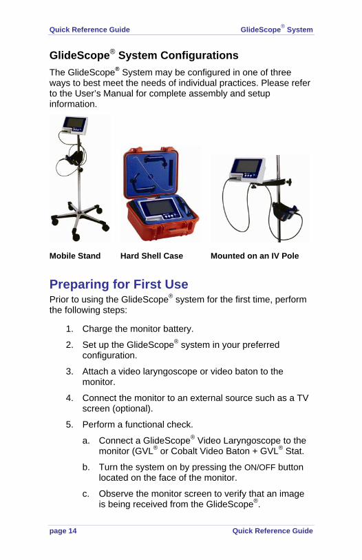
GlideScope® System Configurations The GlideScope® System may be configured in one of three ways to best meet the needs of individual practices. Please refer to the User’s Manual for complete assembly and setup information.
Mobile Stand Hard Shell Case Mounted on an IV Pole
Preparing for First Use Prior to using the GlideScope® system for the first time, perform the following steps:
1. Charge the monitor battery.
2. Set up the GlideScope® system in your preferred configuration.
3. Attach a video laryngoscope or video baton to the monitor.
4. Connect the monitor to an external source such as a TV screen (optional).
5. Perform a functional check.
a. Connect a GlideScope® Video Laryngoscope to the monitor (GVL® or Cobalt Video Baton + GVL® Stat.
b. Turn the system on by pressing the ON/OFF button located on the face of the monitor.
c. Observe the monitor screen to verify that an image is being received from the GlideScope®.

GlideScope® System Quick Reference Guide
Quick Reference Guide page 15
Cleaning and Maintenance To ensure patient safety, users should perform a routine inspection of the GlideScope® Video Laryngoscope before every use to ensure that all endoscopic components are free of unintended rough surfaces, sharp edges, protrusions or cracks.
If inspection reveals any faults in the components, contact Verathon Medical® Customer Care or your local GlideScope® representative. All repairs must be performed by an authorized representative of Verathon Medical®.
CAUTION: Risk of permanent device damage!
Do not expose GlideScope® Video Laryngoscopes or Cobalt Video Batons to temperatures above 140° F (60°C).
Cleaning the GVL® and Cobalt Video Baton The GlideScope® GVL® is a non-sterile reusable device. To avoid cross-contamination, The GlideScope® Video Laryngoscope must be disinfected immediately after each use.
The Cobalt Video Baton may be wiped with 70% isopropyl alcohol solution between uses and may be placed in the video baton cradle after the GVL® Stat has been removed.
For more detailed cleaning instructions see the GlideScope® System User's Manual or visit http://www.verathon.com/gs_manuals.htm
The temperature indicator turns black when the GVL® is exposed to temperatures above 140° F (60° C)

Quick Reference Guide GlideScope® System
page 16 Quick Reference Guide
CAUTION: Risk of equipment damage. Do not use bleach on the Cobalt Video Baton. Bleach will corrode the stainless steel inserts.
NOTE: The Cobalt Video Baton will not be damaged if it is immersed in water, the Steris® 20 Sterilant used in the Steris System 1® Sterile Processing System, or if it is wiped with a 70% IPA solution.
Availability of disinfection products varies by country, and we are unable to test products in every market. Please use the list of recommended disinfectants in the User's Manual to compare with products available locally. If you are uncertain about the suitability of a disinfectant, please contact Verathon Medical® Customer Care or your local Verathon Medical® Customer Care Representative.
Weekly Inspections Once a week, inspect the exterior surfaces of the GlideScope® System components: GVL®s, GVL® Stats, video batons, cables, and video monitor. Any apparent cracks or flaws must be immediately referred to an authorized GlideScope® service center, your local GlideScope® distributor, or your local GlideScope® representative. Refer to page 2 for contact information.
Battery Replacement and Device Repair GlideScope® GVL® System Video Laryngoscopes and Video Monitors do not contain any user-serviceable components. All service and repair must be performed by Verathon®-authorized service technicians. Any attempt to disassemble a GlideScope® device may void the warranty. If your GlideScope® device is not operating normally and requires service please contact your local GlideScope® representative.
Device Disposal Disposal of this device can be coordinated through your Verathon Medical® Service Center in accordance to the WEEE requirements.

GlideScope® System Quick Reference Guide
Quick Reference Guide page 17
Specifications General Specifications Classification: Electrical Class I, Applied Part BF Line Voltage Range: 100 – 240 VAC, 50 & 60 Hz Line Current: MAX 0.50 A Power Plug: Hospital Grade Line Protection: 2A Fuse, Internal
Operation and Storage Conditions Operating: -4° F (-20° C) to 122° F (50° C) Storage: 32° F (0° C) to 113° F (45° C) Pollution Degree: 1
Standards and Approvals CMDCAS ISO 13485, Certificate No. 9235, EC Certificate for Class I sterile Stats, Certificate No. 41315937, MDD Requirements met for Class I and Class I sterile devices, CSA Requirements met (Master Contract # 213281), CSA Certificates issued, CB Scheme requirements met (CB Bulletin 112a), CB Test Certificates issued, CAN/CSA C22.2 No 601.1-M90, CAN/CSA C22.2 No. 60601-2-18-01, UL Std No 60601-1, IEC 60601-2-18, CE Mark EMC Directive, IEC 60601-1-2, CISPR 11, VCCI Technical V-3
Symbol Directory The following international regulatory symbols are found on the GlideScope® Video Laryngoscope and/or GlideScope® Video Monitor and indicate compliance with international regulatory standards:
Symbol Meaning
Type BF equipment
CE mark in accordance with the Medical Device Directive. Class I Device.
Canadian CSA Symbol
FCC Symbol
Attention – consult accompanying documents. Read instructions before connecting or operating
Subject to WEEE (Waste of Electronic Electrical Equipment) regulations


GlideScope® GVL® and Cobalt
User’s Manual


GlideScope® GVL® and Cobalt
User’s Manual

Corporate Headquarters: Verathon Inc. 20001 North Creek Parkway, Bothell, WA 98011 USA 800.331.2313 (Canada and US) 425.867.1348 Fax: 425.883.2896 http://www.verathon.com
Verathon Medical (Europe) B.V. Boerhaaveweg 1 3401 MN IJsselstein The Netherlands +31.30.68.70.570 Fax: +31.30.68.70.512 http://www.verathon.eu
Verathon Medical (Canada) ULC4224 Manor Street Burnaby, BC V5G 1B2 Canada 604.439.3009 Fax: 604.439.3039
For additional contact information please refer to page 54 or visit our corporate website: http://www.verathon.com.
GlideScope®, GVL®, GlideRite®, Verathon® and Verathon Medical® are either trademarks or registered trademarks of Verathon® Inc. in the US and/or other countries.
Cidex® is a registered trademark of Advanced Sterilization Products, a Johnson & Johnson Company. Manu-Klenz® is a registered trademark of Steris Corporation. MetriCide® is a registered trademark of Suborn Dental Specialties, Inc. Sterrad® is a registered trademark of Johnson & Johnson Gateway, LLC.
The GlideScope® technology is covered under US Patents (6,655,377) (6,543,447) (6,142,144) as well as European Patent 1307131. Additional patents pending.
Information in this User’s Manual may change at any time without notice. For the latest version of this manual, refer to www.verathon.com.
Copyright © 2008 by Verathon Inc. All rights reserved. No part of this manual may be copied or transmitted by any method without the express written consent of Verathon Inc.
PN: 0900-2101-00-60
GlideScope® System Contents
User’s Manual page 3
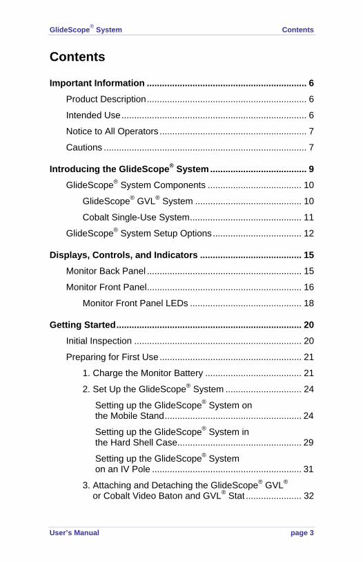
Contents
Important Information ............................................................... 6 Product Description ............................................................... 6 Intended Use ......................................................................... 6 Notice to All Operators .......................................................... 7 Cautions ................................................................................ 7
Introducing the GlideScope® System ...................................... 9 GlideScope® System Components ..................................... 10
GlideScope® GVL® System .......................................... 10 Cobalt Single-Use System ............................................ 11
GlideScope® System Setup Options ................................... 12
Displays, Controls, and Indicators ........................................ 15 Monitor Back Panel ............................................................. 15 Monitor Front Panel ............................................................. 16
Monitor Front Panel LEDs ............................................ 18
Getting Started ......................................................................... 20 Initial Inspection .................................................................. 20 Preparing for First Use ........................................................ 21
1. Charge the Monitor Battery ...................................... 21
2. Set Up the GlideScope® System .............................. 24 Setting up the GlideScope® System on the Mobile Stand ...................................................... 24
Setting up the GlideScope® System in the Hard Shell Case ................................................. 29 Setting up the GlideScope® System on an IV Pole ........................................................... 31
3. Attaching and Detaching the GlideScope® GVL® or Cobalt Video Baton and GVL® Stat ...................... 32
Contents GlideScope® System
page 4 User’s Manual
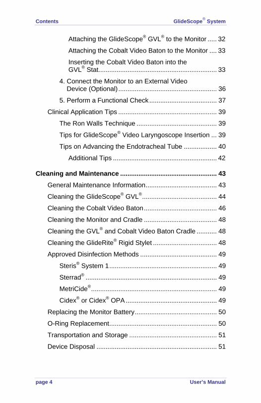
Attaching the GlideScope® GVL® to the Monitor ..... 32 Attaching the Cobalt Video Baton to the Monitor .... 33 Inserting the Cobalt Video Baton into the GVL® Stat................................................................. 33
4. Connect the Monitor to an External Video Device (Optional) ...................................................... 36 5. Perform a Functional Check ..................................... 37
Clinical Application Tips ...................................................... 39 The Ron Walls Technique ............................................ 39 Tips for GlideScope® Video Laryngoscope Insertion ... 39 Tips on Advancing the Endotracheal Tube .................. 40
Additional Tips ......................................................... 42
Cleaning and Maintenance ..................................................... 43 General Maintenance Information ....................................... 43 Cleaning the GlideScope® GVL® ......................................... 44 Cleaning the Cobalt Video Baton ........................................ 46 Cleaning the Monitor and Cradle ........................................ 48 Cleaning the GVL® and Cobalt Video Baton Cradle ........... 48 Cleaning the GlideRite® Rigid Stylet ................................... 48 Approved Disinfection Methods .......................................... 49
Steris® System 1 ........................................................... 49 Sterrad® ........................................................................ 49 MetriCide® ..................................................................... 49 Cidex® or Cidex® OPA .................................................. 49
Replacing the Monitor Battery ............................................. 50 O-Ring Replacement ........................................................... 50 Transportation and Storage ................................................ 51 Device Disposal .................................................................. 51
GlideScope® System Contents
User’s Manual page 5
GlideScope® Warranty Offerings ........................................... 52 Original First Year Total Customer CareSM Warranty ......... 52
What is Covered ........................................................... 53 Premium Customer CareSM Warranty ........................... 53 Disclaimer of Additional Warranties .............................. 53
Contact Information ............................................................. 54
Parts and Accessories ............................................................ 55
Specifications .......................................................................... 57 General Specifications ........................................................ 57 Operating and Storage Conditions ...................................... 57 GlideScope® System Components ..................................... 57 Standards and Approvals .................................................... 60
Contact Information ...................................................... 61
Symbol Directory ..................................................................... 62

Important Information GlideScope® System
page 6 User’s Manual
Important Information Product Description The GlideScope® Video Laryngoscope (GVL®) System incorporates a miniature, autofocusing, high-resolution color camera, an LED light source, a rechargeable lithium battery, and NTSC video output for remote display or video recording.
The GlideScope® Video Laryngoscope System is useful for anterior airways, neonatal intubations, obese patients, and patients with limited neck extension. Additionally, it is useful for teaching purposes, verification of endotracheal (ET) position, nasal intubation, and ET exchange.
The GVL® System is recommended for use with an endotracheal tube stylet, particularly the GlideRite® Rigid Stylet.
Intended Use
Statement of Prescription Federal (USA) law restricts this device for sale by or on the order of a physician.
The GlideScope® Video Laryngoscope System should be used only by individuals who have been trained and authorized by a physician or the institution providing patient care.
Intended Use
GlideScope® Video Laryngoscopes are intended for use by qualified medical professionals to obtain a clear, unobstructed view of the vocal cords for medical procedures
Important Information

GlideScope® System Important Information
User’s Manual page 7
Notice to All Operators All operators should read this entire User’s Manual prior to using the GlideScope® System. Failure to follow these instructions may result in patient injury, comprise the performance of the system, and may void the system warranty.
Verathon® recommends that new GlideScope® users:
Practice using the GVL® or Cobalt on a mannequin before clinical use
Acquire clinical experience on patients without airway abnormalities
Refer to page 39 for recommended techniques.
Cautions
Caution. Risk of permanent equipment damage. Do not expose GlideScope® Video Laryngoscopes or Cobalt Video Batons to temperatures above 140° F (60° C). Do not disinfect or sterilize GlideScope® Video Laryngoscopes or Cobalt Video Batons using devices such as autoclaves, ultrasonic cleaners, or pasteurizers. Use of such methods to disinfect/sterilize GlideScope® Video Laryngoscopes or Cobalt Video Batons will cause permanent device damage and void the warranty. Refer to page 49 for a list of approved cleaning procedures and products.
MDD Class 1 Equipment Caution: Electrical shock hazard. Refer servicing to qualified personnel. This equipment has been tested and found to comply with the standards listed in the Approvals section of this manual (page 60). These limits are designed to provide reasonable protection against harmful interference in typical medical installations.
This equipment generates, uses, and can radiate radio frequency energy and if used properly is very unlikely to cause harmful interference to any other device(s) in the vicinity.
Important Information GlideScope® System
page 8 User’s Manual
However, there is no guarantee that interference will not occur in a particular installation. Interference can be determined by turning the equipment on and off. If this equipment does cause interference with other devices, try to correct the interference by one or more of the following measures:
Re-orient or relocate the receiving device
Increase the separation between equipment
Connect the equipment to an outlet on a circuit different from that to which the other device(s) is (are) connected
Consult your Verathon Medical® Customer Care representative
NOTE: GlideScope® Video Laryngoscopes must be used with the supplied cables to maintain electromagnetic interference (EMI) within certified limits.
Users should be aware that portable and mobile equipment (cellular phones, etc.) can affect medical electrical equipment and take appropriate precautions during operation.

GlideScope® System Introduction
User’s Manual page 9
Introducing the GlideScope® System GlideScope® Video Laryngoscopes (GVL®) are designed for “1st pass success.” They provide a consistently clear view of a patient’s airway, enabling quick intubation. GlideScope® Video Laryngoscopes are clinically proven to achieve a Cormack-Lehane Grade I or II view 99% of the time.1
All GVL® models include an integrated, high-resolution, CMOS camera, LED light source, and a patented anti-fog mechanism. They connect directly to a color video monitor for real time viewing, video output, and recording. The GlideScope® System is available in both, reusable GVL® and single-use Cobalt versions, in a comprehensive range of versions and range of sizes, allowing clinicians to meet the particular requirements of patients ranging in size from neonatal infants to morbidly obese adults.
The GlideScope® Video Laryngoscope is an ideal tool for physicians and other healthcare professionals who need to effectively manage standard to difficult airways. The GlideScope® System is easy to learn, use, and teach. It is ideal for acute care settings and emergency environments. It also integrates easily into standard ED, OR, ICU, and NICU applications.
GlideScope® Video Laryngoscopes may be useful for the following procedures:
First use intubations, replacing Direct Laryngoscopy (DL)
Normal or restricted oropharyngeal views/visualization and assessment of the oropharynx
Cormack-Lehane grades I - IV laryngeal views
1 Cooper RM. Cardiothoracic Anesthesia, Respiration and Airway; Early clinical experience with a new video laryngoscope (GlideScope®) in 728 patients. Canadian Journal of Anesthesia. 2005; 52: 2: 191–198.
Introducing the GlideScope® System
Introduction GlideScope® System
page 10 User’s Manual
Trauma airways - excellent when dealing with blood and secretions in the airway
Airway management in morbidly obese patients
Preterm and neonatal intubations
Cervical spine immobilization
Reintubation in Intensive Care Unit (ICU) settings
Supervision and documentation of the laryngoscopy
Nasal tracheal intubation
Insertion of transesophageal echocardiac probes
Laryngoscopic foreign body removal
Awake intubation for difficult airway management
Insertion of double lumen tubes
Teaching the anatomy of the airway
GlideScope® System Components Two interchangeable video laryngoscope systems are available: the reusable GVL® and Cobalt Single-Use System. Please refer to page 55 for a complete listing of GlideScope® System components and part numbers.
GlideScope® GVL® System The GlideScope® GVL® System includes:
The GlideScope® Video Monitor
One reusable GVL®. The GVL® is comprised of a medical-grade plastic shell that houses a high-resolution CMOS camera, LED light source, and patented anti-fogging mechanism. The GVL® device is available in four sizes. Additional units may be purchased separately.
Video cable (connects the GVL® to the monitor)
GlideRite® Rigid Stylet

GlideScope® System Introduction
User’s Manual page 11
Figure 1. GVL® System components.
Cobalt Single-Use System
The Cobalt Single-Use System includes:
The GlideScope® Video Monitor
Reusable video baton with integrated video cable. The Cobalt Video Baton includes a high-resolution CMOS camera, LED light source, and a patented anti-fogging mechanism. The Cobalt Video Baton is available in two sizes and each baton supports two sizes of GVL® Stats.
GVL® Stats (sterile, single-use blades based on the current GlideScope® GVL® design) - four sizes are available
One GlideRite® Rigid Stylet
GlideScope® non-glare color Video Monitor
Reusable GVL® (4 sizes)
Video cable
GlideRite®
Rigid Stylet

Introduction GlideScope® System
page 12 User’s Manual
Figure 2. Cobalt Single-Use System.
GlideScope® System Setup Options The GlideScope® Video Monitor, Video Laryngoscopes, and related accessories may be set up in various configurations in order to best meet the needs of your facility. The GlideScope® System may be:
Mounted on a mobile stand (Figure 3)
Secured in a hard shell case for remote or emergency applications (Figure 4)
Mounted on an IV pole (user-supplied) for use in clinics and hospitals (Figure 5)
Single-Use GVL® Stats(4 sizes)
GlideRite®
Rigid Stylet
GlideScope®
non-glare color Video Monitor
ReusableCobalt Video Batons (2 sizes)

GlideScope® System Introduction
User’s Manual page 13
Figure 3. GlideScope® System - on mobile stand.
GlideScope®
Monitor PN: 0231-0003
GVL® CradlePN: 0810-0126
Cobalt Cradle 3-4PN: 0810-0134 Cobalt Cradle 1-2PN: 0810-0151
Mobile Stand PN: 0800-0299
GVL® Video CablePN: 0600-0237

Introduction GlideScope® System
page 14 User’s Manual
Figure 4. GlideScope® System - in hard shell case.
Figure 5. GlideScope® System - on IV pole (user-supplied).
GlideScope®
Video Monitor PN: 0231-0003
IV pole(user provided)
IV pole mountPN: 0810-0125
GVL® Cradle PN: 0810-0126
Hard shell casePN: 0800-0300
GlideScope®
Video Monitor PN: 0231-0003

GlideScope® System Displays, Controls, and Indicators
User’s Manual page 15
Displays, Controls, and Indicators Monitor Back Panel The GlideScope® Video Monitor back panel (Figure 6) contains the power cord connector, accessory video output connector, battery ON/OFF slider switch, and a mounting point for the optional mobile stand, IV pole, or hard shell case.
Figure 6. GlideScope® Video Monitor back panel.
Displays, Controls, and Indicators
Power cordconnector
Batteryswitch
ON/OFF
NTSC video outputconnector (for external monitor)
Mounting point for mobile stand, IV pole, or hard shell case

Displays, Controls, and Indicators GlideScope® System
page 16 User’s Manual
Monitor Front Panel The GlideScope® Video Monitor front panel (Figure 7) contains the video cable connector, two battery status LEDs, and four buttons: MENU, UP, DOWN, and ON/OFF. Button functions are described in Table 1 on the next page.
Figure 7. GlideScope® Video Monitor front panel.
Table 1. Monitor front panel buttons.
Button Function
ON/OFF
Press to turn the GlideScope® System ON/OFF.
UP DOWN
Press to increase/decrease monitor setting values.
MENU
Press the MENU button repeatedly, to make selections from the displayed list of options. A menu item is selected (active) when highlighted in yellow. Display settings include:
Video cableconnector
Chargestatus LED
Batterystatus LED

GlideScope® System Displays, Controls, and Indicators
User’s Manual page 17
Brightness: When BRIGHTNESS is highlighted, press UP/DOWN to increase/decrease luminosity. A brightness setting of 18 - 20 units is recommended.
Contrast: When CONTRAST is highlighted, press UP/DOWN to increase/decrease image contrast. A contrast setting of 16 - 20 units is recommended.
Color: When COLOR is highlighted, press UP/DOWN to increase/decrease displayed color saturation. The default setting of 50 units (on a scale of 0 - 100 units) is recommended.
Mirror: Press UP to display a mirror image of the displayed image. Press DOWN to return to the original view.
Reset: Pressing either UP or DOWN will return all monitor settings to the factory defaults.
Exit: When EXIT is highlighted, press either UP or DOWN to save all settings and return to the viewing screen.
Normal, NTSC, AV1: These three items display the format and channel of the signal that is being received from the GlideScope®. Since all GlideScope® cameras use the NTSC format, these settings will not change.
NOTE: VOLUME and MUTE may appear on some monitor screens. These features are currently inactive.

Displays, Controls, and Indicators GlideScope® System
page 18 User’s Manual
Monitor Front Panel LEDs
The monitor front panel has two status LEDs that indicate battery usage and charge states (Figure 8).
The battery indicator LED illuminates when the monitor is operating on battery power
The charge status LED indicates the battery charge level as explained in Table 2, on the next page
Figure 8. Front panel LEDs indicate battery usage and charge status.

GlideScope® System Displays, Controls, and Indicators
User’s Manual page 19
Table 2. Charge status LED states.
No LED
The battery is completely depleted and needs to be recharged.
Steady green
The battery is fully charged and ready for use.
Flashing green
Battery power is low and needs charging. The LED flashes for approximately five minutes before shutting off.
Flashing green with beeping
There is approximately one more minute of battery power remaining.
Flashing orange
Flashing orange can indicate two states:
If the AC power is connected and the battery switch is OFF (to the left), the charge status LED will flash orange. The monitor will still function but the battery will not charge.
If the AC power is NOT connected and the charge status LED flashes orange, the battery is malfunctioning. Please consult your Verathon Medical® Customer Care representative.
Steady orange
Charging in progress

Getting Started GlideScope® System
page 20 User’s Manual
Getting Started Initial Inspection Upon receipt, inspect the components of the GlideScope® Video Laryngoscope System for any obvious physical damage that may have occurred during shipment. Verathon Medical® recommends that the inspection be performed by a biomedical engineer or other qualified professional who is familiar with electronic medical devices.
The components you receive will vary depending on which configuration was ordered (see Figure 3). To verify that you have received the appropriate components, refer to the packing list included with your system.
If any of the components are missing or damaged, notify the carrier and Verathon Medical® Customer Care immediately at:
800.331.2313 (Canada and US)
425.867.1348 (International)
+31.30.68.70.570 (Europe)
Please refer to page 54 for additional contact information,
Getting Started

GlideScope® System Getting Started
User’s Manual page 21
Preparing for First Use Prior to using the GlideScope® System for the first time, perform the following steps:
1. Charge the monitor battery (instructions begin on this page).
2. Set up the GlideScope® System in your preferred configuration (instructions begin on page 24).
3. Attach a video laryngoscope to the monitor (instructions begin on page 32).
4. Connect the monitor to an external source such as a TV screen or NTSC video monitor (optional).
5. Perform a functional check (instructions begin on page 37).
1. Charge the Monitor Battery
The GlideScope® System can operate on AC power (wall current) or battery power.
The GlideScope® Monitor contains a lithium battery that provides power to the GlideScope® Video Laryngoscope. Under normal conditions, the battery will last approximately 90 minutes before it needs to be recharged.
IMPORTANT! The battery must be fully charged prior to first use.
For optimal battery life:
The battery must be fully charged before first use in battery mode
When the battery is low, the charge status LED (on the monitor front panel) will flash green for approximately five minutes

Getting Started GlideScope® System
page 22 User’s Manual
When the battery is nearly depleted, the charge status LED will flash green and beep. This indicates that the battery has approximately one minute of power remaining.
The monitor battery should be charged at room temperature, between 32° - 104° F (0° - 40° C)
To charge the monitor battery:
IMPORTANT! Before beginning, make sure the AC power cord is disconnected and the battery switch (on the monitor rear panel) is in the OFF position (to the left).
1. Slide the battery switch to the ON position (to the right) (Figure 9).
2. Insert the female end of the power cord into the power cord connector on the back of the monitor (Figure 9).
Figure 9. Rear panel detail: AC power cord connector and battery switch in the ON position.
3. Insert the other end of the power cord into a wall outlet or appropriate AC power source. NOTE: For power supply compatibility information, please refer to the label on the back of the monitor.
Power cord connector
Battery switch in the ON position

GlideScope® System Getting Started
User’s Manual page 23
4. The charge status LED will turn orange, indicating that the charging cycle has begun. When the battery is fully charged, the charge status LED will turn green (Figure 10). At this point the system is fully functional on battery power.
Figure 10. The charge status LED will turn green when the battery is fully charged.
NOTE: For more information about charge status LED states, refer to Table 2 on page 19.
Getting Started GlideScope® System
page 24 User’s Manual
2. Set Up the GlideScope® System
The GlideScope® System may be set up in one of three configurations:
On a mobile stand (Figure 3)
In a hard shell case (Figure 4)
On an IV pole (Figure 5)
Setting up the GlideScope® System on the Mobile Stand
(Refer to Figure 3, page 13)
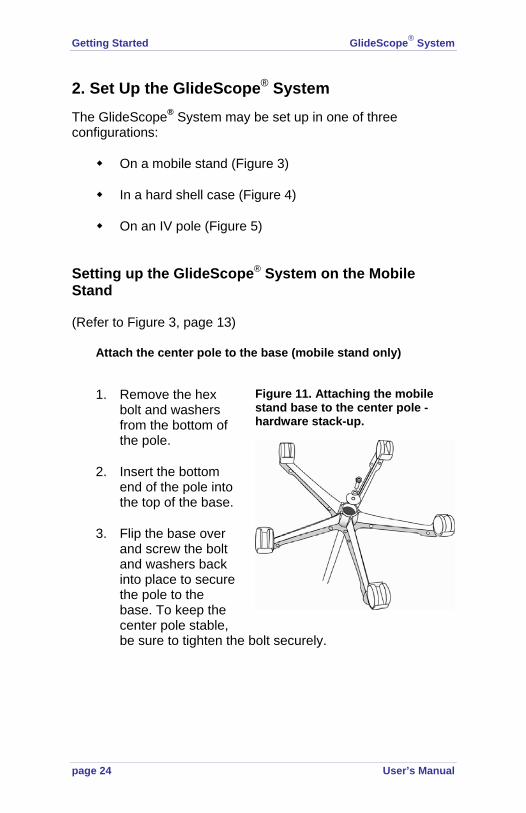
Attach the center pole to the base (mobile stand only)
1. Remove the hex bolt and washers from the bottom of the pole.
2. Insert the bottom end of the pole into the top of the base.
3. Flip the base over and screw the bolt and washers back into place to secure the pole to the base. To keep the center pole stable, be sure to tighten the bolt securely.
Figure 11. Attaching the mobile stand base to the center pole - hardware stack-up.

GlideScope® System Getting Started
User’s Manual page 25
4. To reinsert the mobile stand wheels: insert the wheel pin into the opening on the end of the mobile stand base (Figure 12). Applying steady, moderate force, press the wheel pin into the base until it snaps into place.
To Remove the Mobile Stand Wheels
The mobile stand wheels may be removed to facilitate storage and transportation.
Using steady, moderate force, pull the wheels away from the base.
Adjust the Height of the Mobile Stand (Figure 13)
1. Loosen the black height adjustment knob located on the mobile stand pole by turning it counterclockwise.
2. Raise or lower the pole to the desired height.
3. Secure the pole in position by turning the height adjustment knob clockwise.
Figure 12. Removing and inserting the wheels from the mobile stand.

Getting Started GlideScope® System
page 26 User’s Manual
Figure 13. Adjusting the height of the mobile stand.
Attach the Monitor to the Mobile Stand
Hold the monitor against the screw on the tilt head and turn the tilt head fastener clockwise to tighten (Figure 14).
Adjust the Monitor Angle
Before use, the angle of the monitor should be adjusted for optimal viewing. The ideal angle will be determined by the working position of the monitor and the user.
To adjust the angle of the monitor:
1. Loosen the angle adjustment knob located on the tilt head of the IV pole mount by turning it counterclockwise.
2. Tilt the monitor to the desired angle.
3. Secure the monitor in place by turning the angle adjustment knob clockwise (Figure 14).

GlideScope® System Getting Started
User’s Manual page 27
Figure 14. Attaching the monitor to the mobile stand.
Attach the GVL® Cradle
To attach the GVL® Cradle:
1. Open the cradle latch and position the mobile stand pole on the back of the cradle.
2. Close the cradle latch and tighten in place by turning the black cradle adjustment knob clockwise (Figure 15).
Figure 15. Attaching the GVL® Cradle to the mobile stand.
Figure 16. GlideScope® GVL®s in the cradle bays.
Tilt head fastener
Angleadjustment
knob

Getting Started GlideScope® System
page 28 User’s Manual
Attach the Cobalt Video Baton Cradle
The Cobalt Video Baton Cradle may be mounted either to the GVL® Cradle or directly to the mobile stand center pole. Directions for mounting to the center pole begin on page 28.
To attach the Cobalt Video Baton Cradle to the GVL® Cradle:
1. Attach the GVL® Cradle to the mobile stand as shown in Figure 15.
2. Hook the Cobalt Cradle into the GVL® Cradle as shown in Figure 17.
Figure 17. Attaching the Cobalt Video Baton Cradle to the GVL® Cradle.
To attach the Cobalt Video Baton cradle directly to the mobile stand or IV pole:
1. Attach the center pole clamp to the Cobalt Cradle.
2. Attach the center pole clamp and Cobalt Video Baton Cradle to the mobile stand or IV pole and turn the black knob clockwise to tighten.

GlideScope® System Getting Started
User’s Manual page 29
Figure 18. Attaching the center pole clamp to the Cobalt Cradle.
Setting up the GlideScope® System in the Hard Shell Case
Refer to Figure 19 page 30.
The hard shell case comes with a custom foam insert designed to protect the GlideScope® System components. To secure the monitor in the hard shell case:
1. Remove the foam insert from the bottom of the hard shell case.
2. Remove the screw from the foam insert.
3. Align the foam insert with the monitor rear panel so that the battery switch remains accessible.
4. Screw the foam insert to the monitor until the screw is snug (Figure 19). Do not over-tighten the screw.
Mobile stand clamp
Mobile stand pole

Getting Started GlideScope® System
page 30 User’s Manual
Figure 19. Removing the video monitor from the hard shell case.
Removing the Video Monitor From the Hard Shell Case
To remove the monitor from the hard shell case:
1. Grasp the monitor handle and pull the monitor and foam out of the hard shell case.
2. On the back of the foam insert, remove the screw holding the monitor to the foam.
GlideScope® System Getting Started
User’s Manual page 31
Setting up the GlideScope® System on an IV Pole
Refer to Figure 5, page 14.
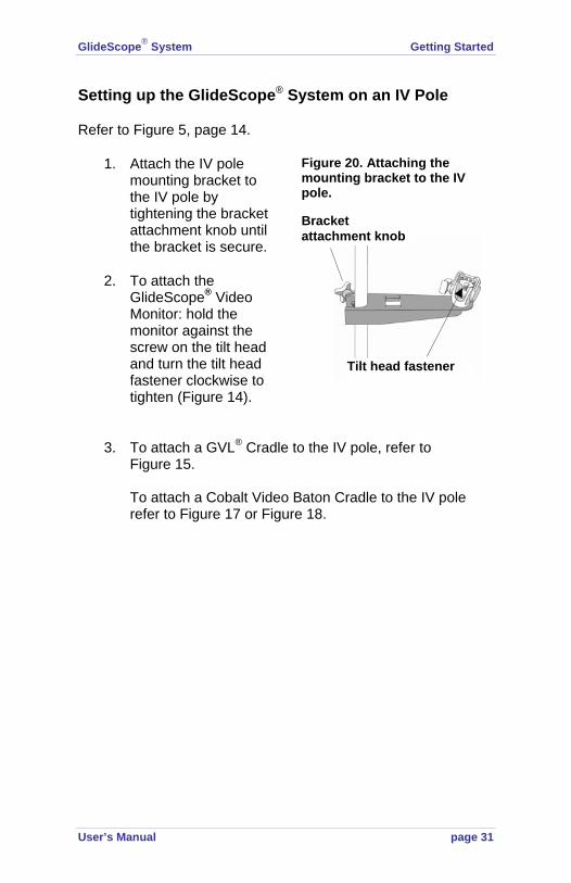
1. Attach the IV pole mounting bracket to the IV pole by tightening the bracket attachment knob until the bracket is secure.
2. To attach the GlideScope® Video Monitor: hold the monitor against the screw on the tilt head and turn the tilt head fastener clockwise to tighten (Figure 14).
3. To attach a GVL® Cradle to the IV pole, refer to Figure 15. To attach a Cobalt Video Baton Cradle to the IV pole refer to Figure 17 or Figure 18.
Figure 20. Attaching the mounting bracket to the IV pole.
Bracket attachment knob
Tilt head fastener

Getting Started GlideScope® System
page 32 User’s Manual
3. Attaching and Detaching the GlideScope® GVL® or Cobalt Video Baton and GVL® Stat
Attaching the GlideScope® GVL® to the Monitor
The GlideScope® GVL® connects to the monitor with a detachable video cable (supplied).
1. Insert the GVL® Video Cable into the connector port located on the face of the monitor so that the arrows on the cable and the monitor are aligned (Figure 21). NOTE: When connecting and disconnecting the cable, grasp the connector by the gray sleeve.
Figure 21. Attaching the GVL® Video Cable to the monitor.
2. Insert the other end of the cable into the port located on the handle of the GVL® (Figure 22).
GVL® Connector Port
GlideScope® System Getting Started
User’s Manual page 33
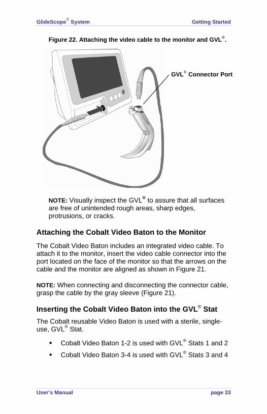
Figure 22. Attaching the video cable to the monitor and GVL®.
NOTE: Visually inspect the GVL® to assure that all surfaces are free of unintended rough areas, sharp edges, protrusions, or cracks.
Attaching the Cobalt Video Baton to the Monitor
The Cobalt Video Baton includes an integrated video cable. To attach it to the monitor, insert the video cable connector into the port located on the face of the monitor so that the arrows on the cable and the monitor are aligned as shown in Figure 21.
NOTE: When connecting and disconnecting the connector cable, grasp the cable by the gray sleeve (Figure 21).
Inserting the Cobalt Video Baton into the GVL® Stat The Cobalt reusable Video Baton is used with a sterile, single-use, GVL® Stat.
Cobalt Video Baton 1-2 is used with GVL® Stats 1 and 2
Cobalt Video Baton 3-4 is used with GVL® Stats 3 and 4
GVL® Connector Port

Getting Started GlideScope® System
page 34 User’s Manual
To insert the Cobalt Video Baton into the GVL® Stat:
1. Insert the Cobalt Video Baton into the GVL® Stat until it clicks into place (Figure 23).
Figure 23. Inserting the Cobalt Video Baton into the GVL® Stat.
2. Ensure proper insertion by aligning the wide collar of the video baton to the wide collar of the GVL® Stat; or match the GlideScope® logo on the side of the video baton with GlideScope® logo on the side of the GVL® Stat. Be sure not to insert the video baton backwards (Figure 24). If the video baton does become stuck, insert a tongue depressor into the GVL® Stat shell to release the video baton.
Cobalt Video Baton
GVL® Stat

GlideScope® System Getting Started
User’s Manual page 35
Figure 24. Do not insert the video baton backwards.
NOTE: Visually inspect the GVL® Stat to ensure that all exterior surfaces are free of unintended rough areas, sharp edges, protrusions, or cracks.
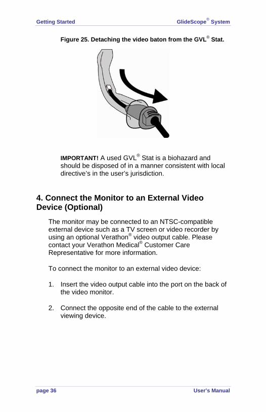
Detaching the Cobalt Video Baton from the GVL® Stat
The GVL® Stat is a single-use device. After each use, it should be removed from the Cobalt Video Baton and disposed of properly.
To detach the Cobalt Video Baton from the GVL® Stat, grasp the handle of video baton and pull firmly (Figure 25).
Getting Started GlideScope® System
page 36 User’s Manual
Figure 25. Detaching the video baton from the GVL® Stat.
IMPORTANT! A used GVL® Stat is a biohazard and should be disposed of in a manner consistent with local directive’s in the user’s jurisdiction.
4. Connect the Monitor to an External Video Device (Optional)
The monitor may be connected to an NTSC-compatible external device such as a TV screen or video recorder by using an optional Verathon® video output cable. Please contact your Verathon Medical® Customer Care Representative for more information.
To connect the monitor to an external video device:
1. Insert the video output cable into the port on the back of the video monitor.
2. Connect the opposite end of the cable to the external viewing device.

GlideScope® System Getting Started
User’s Manual page 37
Figure 26. Attaching a video output cable to the monitor.
5. Perform a Functional Check
Prior to first use, perform the following functional check to assure that the GlideScope® System is working properly. Please contact your Verathon Medical® Customer Care Representative if your GlideScope® System does not function as described below.
To perform a functional check of the GlideScope® System:
1. Fully charge the monitor battery (see page 21).
2. Connect a GlideScope® Video Laryngoscope to the monitor (GVL® or Cobalt Video Baton + GVL® Stat, see page 32).
3. Slide the battery switch on the back of the monitor to the ON (to the right) position.
To external device

Getting Started GlideScope® System
page 38 User’s Manual
4. Turn the system on by pressing the ON/OFF button located on the face of the monitor.
5. Observe the monitor screen to verify that an image is being received from the GlideScope® (Figure 27). NOTE: The upper left corner of the LCD screen will display a small portion of the GVL® Blade (Figure 27). The blade is captured in the view due to the wide-angle properties of the camera lens. This opaque portion acts as a frame of reference during the intubation process and assures that the orientation of the image is correct in the monitor.
Figure 27. When the power is on, one corner of the GVL® blade is visible in the display.
Portion of GlideScope® blade (frame of reference)

GlideScope® System Getting Started
User’s Manual page 39
Clinical Application Tips The Ron Walls† Technique
1. First look at the patient’s mouth directly when introducing the GlideScope® GVL ® into the midline of the oral cavity.
2. Then look at the monitor and elevate the tip of the blade to see the epiglottis and the glottic opening.
3. Next, look at the mouth to carefully guide the tube and stylet into position near the tip of the laryngoscope.
4. Then look back at the monitor to complete the intubation under direct vision.
Tips for GlideScope® Video Laryngoscope Insertion
1. Verathon Medical® recommends inserting the GlideScope® GVL® down the midline of the tongue to the epiglottis.
2. The GlideScope® GVL® may be used to produce a Macintosh indirect lift of the epiglottis or a Miller lift.
3. Intubations using the GlideScope® GVL® only require approximately 1 to 3.5 lbs (0.5 - 1.5 kgs) of lifting force.
† Ron M. Walls, M.D., Chairman - Department of Emergency Medicine, Brigham and Woman’s Hospital, Professor of Medicine (Emergency Medicine), Harvard Medical School.

Getting Started GlideScope® System
page 40 User’s Manual
4. Verathon Medical® recommends a 90º angle for the endotracheal tube stylet and an ET tube with a soft distal tip. The GlideRite® Rigid Stylet is specifically designed to complement the angulation of the GVL® to facilitate intubation.
5. To aid the passage of the endotracheal tube, withdraw the stylet approximately 2 inches (5 cm) and withdraw the GlideScope® GVL® approximately 1/2 inch (1 - 2 cm).
Tips on Advancing the Endotracheal Tube
1. Select a stylet. The GlideRite® Rigid Stylet is designed to complement the angulation of the GVL® or GVL® Stat and requires no bending or other manipulation (Figure 28). Use of the GlideRite® Rigid Stylet enhances the ease and speed of endotracheal procedures.
Figure 28. The curvature of the GlideRite® Rigid Stylet complements that of the GVL® and GVL® Stat.
If using another type of malleable stylet, Verathon® recommends bending the tip of the stylet to at least 90° to complement the angle of the GVL® or GVL® Stat. An angle larger than 90° may increase the difficulty of advancing the endotracheal tube.

GlideScope® System Getting Started
User’s Manual page 41
2. Introduce the endotracheal tube.
The endotracheal tube should be introduced behind or immediately adjacent to the GVL® or GVL® Stat
The stylet should not enter the larynx during intubation
The proximal tip of the stylet may be bent backward to permit one-handed operation of the endotracheal tube (Figure 29)
The proximal end of the endotracheal tube should be carefully introduced between the vocal folds
The operator should take care not to damage the cuff, teeth, or oropharynx during insertion
3. Withdraw the stylet 2 in (5 cm). Using the right hand, advance the endotracheal tube while simultaneously withdrawing the stylet with the thumb (Figure 29). The stylet should be withdrawn approximately 2 in (5 cm). This straightens the tip of the endotracheal tube and permits it to enter the larynx while the stylet continues to provide rigidity to the body of the endotracheal tube.

Getting Started GlideScope® System
page 42 User’s Manual
Figure 29. The GlideRite® Rigid Stylet is designed for one-handed removal from the endotracheal tube.
Additional Tips
New GlideScope® users often achieve an excellent view with the GVL® or GVL® Stat but may experience some difficulty advancing the endotracheal tube. This may be caused by two factors:
Excessive lifting or pushing of the glottis by the GVL® or GVL® Stat Maximum laryngeal exposure may not facilitate intubation; reducing the elevation applied to the laryngoscope may make inserting the endotracheal tube easier.
Angulation of the tip of the endotracheal tube The GlideRite® Rigid Stylet is designed to complement the angulation of the GVL® or GVL® Stat.
Removing the rigid stylet from the endotracheal tube

GlideScope® System Cleaning and Maintenance
User’s Manual page 43
Cleaning and Maintenance General Maintenance Information Periodic inspections should be performed to ensure safe and effective operation. It is recommended that a qualified technician perform a full visual inspection of all components at least every three months.
The technician should check for the following items:
External damage
Damage to the power supply
Connectors and cable insulation integrity
To ensure patient safety, users should perform a routine inspection of the GlideScope® Video Laryngoscope before every use to ensure that all endoscopic components are free of unintended rough surfaces, sharp edges, protrusions or cracks.
If inspection reveals any faults in the components, contact Verathon Medical® Customer Care. All repairs must be performed by an authorized Verathon Medical® Service Center.
Caution. Risk of permanent equipment damage. Do not expose GlideScope® Video Laryngoscopes or Cobalt Video Batons to temperatures above 140° F (60°C). Do not disinfect or sterilize GlideScope® Video Laryngoscopes or Cobalt Video Batons using devices such as autoclaves, ultrasonic cleaners, or pasteurizers. Use of such methods will cause permanent device damage and void the warranty. Refer to page 49 for a list of approved cleaning procedures and products.
Cleaning and Maintenance

Cleaning and Maintenance GlideScope® System
page 44 User’s Manual
Cleaning the GlideScope® GVL® The GlideScope® GVL® is a non-sterile reusable device. To avoid cross-contamination, the GlideScope® Video Laryngoscope must be disinfected immediately after each use.
Do not place the GlideScope® GVL® in the cradle, in the hard shell case, or other storage until all cleaning procedures have been completed
During cleaning, take care to avoid overheating. Monitor the color of the temperature gauge on the GVL® handle to avoid overheating the GVL® (Figure 30).
The temperature indicator turns black if the GVL® is heated above 140° F (60° C).
A gray indicator does not indicate overheating.
The temperature indicator is white when the GVL® is at room temperature.
Figure 30. Monitor the color of temperature indicator to avoid overheating the GVL®.
Temperatureindicator

GlideScope® System Cleaning and Maintenance
User’s Manual page 45
Caution: Risk of equipment damage. The temperature indicator turns black when the GVL® is exposed to temperatures above 140° F (60° C).
Caution: Risk of equipment damage. Failure to cover the cable connector port with the protective cap prior to cleaning may result in water ingress and potential device failure.
To clean the GlideScope® GVL®:
1. Disconnect the GlideScope® from the video cable.
2. Insert the attached protective cap into the video cable port to protect the electronic connector as shown in Figure 31.
Figure 31. Place the protective cap over the video cable port before cleaning the GVL®.
Protective cap in “standby” position
Correct cleaning position -protective cap covering the electronic connector
Cleaning and Maintenance GlideScope® System
page 46 User’s Manual
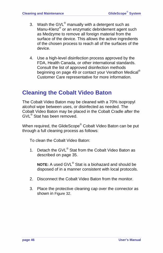
3. Wash the GVL® manually with a detergent such as Manu-Klenz® or an enzymatic debridement agent such as Medzyme to remove all foreign material from the surface of the device. This allows the active ingredients of the chosen process to reach all of the surfaces of the device.
4. Use a high-level disinfection process approved by the FDA, Health Canada, or other international standards. Consult the list of approved disinfection methods beginning on page 49 or contact your Verathon Medical® Customer Care representative for more information.
Cleaning the Cobalt Video Baton The Cobalt Video Baton may be cleaned with a 70% isopropyl alcohol wipe between uses, or disinfected as needed. The Cobalt Video Baton may be placed in the Cobalt Cradle after the GVL® Stat has been removed.
When required, the GlideScope® Cobalt Video Baton can be put through a full cleaning process as follows:
To clean the Cobalt Video Baton:
1. Detach the GVL® Stat from the Cobalt Video Baton as described on page 35. NOTE: A used GVL® Stat is a biohazard and should be disposed of in a manner consistent with local protocols.
2. Disconnect the Cobalt Video Baton from the monitor.
3. Place the protective cleaning cap over the connector as shown in Figure 32.

GlideScope® System Cleaning and Maintenance
User’s Manual page 47
Figure 32. Place the protective cleaning cap over the connector as shown.
4. Wash the Cobalt Video Baton manually with water to remove all foreign material from the surface of the device.
5. The Cobalt Video Baton will not be damaged if it is immersed in water, the Steros 20 Sterilant used in the Steris® System 1 Sterile Processing System, or if it is wiped with 70% IPA. After removal, store the video baton in a clean environment.
Caution: Risk of equipment damage. Do not use bleach on the Cobalt Video Baton. Bleach will corrode the stainless steel inserts.
Correct cleaning position - protective cap covering the electronic connector

Cleaning and Maintenance GlideScope® System
page 48 User’s Manual
Cleaning the Monitor and Cradle Clean the exterior of the monitor and the cradle with IPA (70% Isopropyl Alcohol Solution) wipes.
Cleaning the GVL® and Cobalt Video Baton Cradle Wipe the cradle with a standard hospital-grade surface cleaning product.
Cleaning the GlideRite® Rigid Stylet 1. Remove excess soil by wiping with disposable cloth or
rinsing and brushing.
2. Using a brush, apply detergent such as Manu-Klenz® or an enzymatic debridement agent such as Medzyme to all surfaces. NOTE: Do not clean in chlorine solution. Stainless steel does not resist chlorine in high concentrations.
3. Rinse under clean, running water for 1 minute.
4. Disinfect the GlideRite® Rigid Stylet by using one of the following approved products and methods:
Autoclave
Steris®
Sterrad®
MetriCide®
Cidex®
Products and methods mentioned above should be used according to manufacturer’s specifications.

GlideScope® System Cleaning and Maintenance
User’s Manual page 49
Approved Disinfection Methods The following high-level disinfectants are approved for use:
NOTE: Read and comply with product use instructions in all applications.
Steris® System 1 Place the GVL® or Cobalt Video Baton in the Steris® System 1 machine and begin the cleaning cycle as instructed by Steris®. After removal, the GVL® or Cobalt Video Baton should be kept in a clean environment.
NOTE: Steris® systems that use steam should NOT be used to sterilize the GVL® or Cobalt Video Baton.
Sterrad® Dry the GVL® completely after preliminary cleaning. Complete the cleaning cycle according to the directions provided by Sterrad®.
MetriCide®
Immerse the GVL® in MetriCide® for 20 minutes to complete the requirement. Rinse with sterilized water. After cleaning, thoroughly dry the blade with a clean towel (paper or cloth). Store in a clean environment.
Cidex® or Cidex® OPA
The Cidex® OPA preparation requires 12 minutes of immersion to provide high level protection suitable for laryngoscopes. Immerse the GVL® in Cidex® OPA or Cidex® Standard for 12 minutes to complete the requirement. Following disinfection, rinse with sterilized water, dry and store in a clean environment.
Caution: Risk of equipment damage. Do not use bleach on the Cobalt Video Baton. Bleach will corrode the stainless steel inserts.
Cleaning and Maintenance GlideScope® System
page 50 User’s Manual
Availability of disinfection products varies by country, and we are unable to test products in every market. Please use the list of recommended disinfectants in this manual to compare with products available locally. If you are uncertain about the suitability of a disinfectant, please contact Verathon Medical® Customer Care or your local Verathon® GlideScope® Representative.
Replacing the Monitor Battery Under normal operating conditions, the battery will last 2 - 3 years; or approximately 500 charge/discharge cycles.
The battery is not user-replaceable. In case of battery malfunction, do not attempt to replace the monitor battery. Any attempts to replace the battery by unauthorized service technicians will void the warranty. Please contact your Verathon Medical® Customer Care Representative for more information on battery replacement.
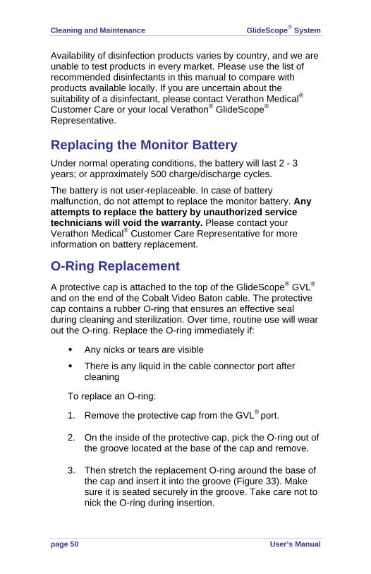
O-Ring Replacement A protective cap is attached to the top of the GlideScope® GVL® and on the end of the Cobalt Video Baton cable. The protective cap contains a rubber O-ring that ensures an effective seal during cleaning and sterilization. Over time, routine use will wear out the O-ring. Replace the O-ring immediately if:
Any nicks or tears are visible
There is any liquid in the cable connector port after cleaning
To replace an O-ring:
1. Remove the protective cap from the GVL® port.
2. On the inside of the protective cap, pick the O-ring out of the groove located at the base of the cap and remove.
3. Then stretch the replacement O-ring around the base of the cap and insert it into the groove (Figure 33). Make sure it is seated securely in the groove. Take care not to nick the O-ring during insertion.

GlideScope® System Cleaning and Maintenance
User’s Manual page 51
Figure 33. Replacing the O-Ring.
Transportation and Storage GlideScope® System components can be safely used and stored under the following environmental conditions:
Relative humidity range of 10 - 90%
Storage temperature range of 32° - 113° F (0° - 45° C)
Figure 34. Prior to shipping, make sure the battery switch is in the OFF position.
IMPORTANT: The battery switch must be in the OFF (left side) position during shipping and storage.
Device Disposal Disposal of this device can be coordinated through your Verathon Medical® Service Center in accordance to the WEEE requirements.
O-ringPN 0120-0335

Warranty GlideScope® System
page 52 User’s Manual
GlideScope® Warranty Offerings Original First Year Total Customer CareSM Warranty Verathon® warrants the GlideScope® System against defects in material and workmanship. This warranty applies for one (1) year from the date of shipment from Verathon®. This warranty is given only to the original purchaser of the GlideScope® System.
If a customer’s system requires service or repair, Verathon® will either replace or provide a loaner unit within one (1) business day from the date of customer service notification. The customer agrees to send the defective unit to Verathon® upon receipt of the loaner unit and agrees to return the loaner unit within two (2) business days of receipt of the repaired unit.
This warranty provides coverage for damage from accidental drops or mishandling. It does not cover damage due to deliberate mishandling.
This warranty does not apply if the product has been damaged due to, or as the result of, service or modification by anyone other than an authorized Verathon® Service Center
This warranty does not apply if there is evidence of the equipment being exposed to temperatures in excess of 60º C
The product shall be used in accordance with the instructions contained in this User’s Manual. Consumable items (i.e., endotracheal tubes, Stats, stylets, etc.) shall be used in conformance to Verathon® product specifications. Consumable items are not covered under this warranty.
GlideScope® Warranty Offerings
GlideScope® System Warranty
User’s Manual page 53
What is Covered
Warranty coverage is extended to the GlideScope® GVL® System:
Video Monitor including Display Connector Cable and Video output Cable (VOC)
o VOC is only covered with an extended warranty for the monitor
GlideScope® Video Laryngoscopes (GVL®)
Cobalt Video Batons
Additional GVLs® (laryngoscopes) purchased either singularly or as a part of a system must be warranted separately.
Additional video monitors purchased either singularly or as part of a system must be warranted separately.
Premium Customer CareSM Warranty
The Premium Customer CareSM warranty from Verathon Medical® may be extended for a total of up to six (6) years from date of purchase.
Disclaimer of Additional Warranties
There are no understandings, agreements, representations of warranties expressed or implied (including warranties of merchantability or fitness for a particular purpose) other than those set forth in the preceding Warranty section. The contents of this manual do not constitute a warranty.
Some states disallow certain limitations on applied warranties. The purchaser, user, and patient should consult state law if there is a question regarding this disclaimer. This information, descriptions, recommendations, and safety notations in this manual are based upon Verathon® experience and judgment with GlideScope® GVL® Systems as of September 2008. The contents of this manual should not be considered to be all-inclusive, or to cover all contingencies.

Warranty GlideScope® System
page 54 User’s Manual
Contact Information To obtain additional information regarding your GlideScope® Video Laryngoscope System, please contact Verathon Medical® Customer Care at:
Corporate HQ: (US and Canada) Verathon Inc. 20001 North Creek Parkway Bothell, WA 98011-8128 USA 800.331.2313 (Canada and US) 425.867.1348 Fax: 425.883.2896 http://www.verathon.com
Verathon Medical (United Kingdom) Ltd. The Granary Manor Farm Courtyard Aston Sandford, Aylesbury Buckinghamshire, HP17 8JB United Kingdom +44.1844.299.207 Fax: +44.1844.299.218 http://www.verathon.co.uk/
Verathon Medical (Europe) B.V. Boerhaaveweg 1 3401 MN lJsselstein The Netherlands +31.30.68.70.570 Fax: +31.30.68.70.512 http://www.verathon.eu/
Verathon Medical (Japan) K.K. Executive Tower Azabudai 7F 1-4-3 Azabudai Minato-ku Tokyo, Japan 106-0041 +81.03.3560.3501 Fax: +81.03.3560.3502
Verathon Medical (France) Sarl Espace Europeen de l’Entreprise2 allée d’Oslo BP 10039 Schiltigheim F-67012 Strasbourg Cedex France +33.03.88.60.14.02 Fax: +33.(0)3.88.60.46.87
Manufacturer: Verathon Medical (Canada) ULC 4224 Manor Street Burnaby, BC V5G 1B2 Canada 604.439.3009 Fax: 604.439.3039

GlideScope® System Parts and Accessories
User’s Manual page 55
Parts and Accessories Table 3. GlideScope® System Components and Accessories.
Description Part Number
GlideScope® Video Laryngoscope GVL® 5 0574-0030
GlideScope® Video Laryngoscope GVL® 4 0574-0001
GlideScope® Video Laryngoscope GVL® 3 0574-0007
GlideScope® Video Laryngoscope GVL® 2 0574-0010
GlideScope® Cobalt Video Baton 3-4 0570-0185
GlideScope® Cobalt Video Baton 1-2 0570-0210
GVL® Stat 4, Qty 10 0270-0444
GVL® Stat 3, Qty 10 0270-0446
GVL® Stat 2, Qty 10 0270-0429
GVL® Stat 1, Qty 10 0270-0428
GVL® Stat 4, Qty 100 0270-0445
GVL® Stat 3, Qty 100 0270-0447
GVL® Stat 2, Qty 100 0270-0431
GVL® Stat 1, Qty 100 0270-0430
Cobalt Video Baton 3-4 Kit (includes Stats) 0270-0382
Cobalt Video Baton 1-2 Kit (includes Stats) 0270-0608
Portable Video Monitor, GVL® 0231-0003
GlideRite® Rigid Stylet (Package of Six) 0803-0009
GlideScope® GVL® Cradle 0810-0126
GlideScope® Video Baton Cradle 3-4 0810-0134
GlideScope® Video Baton Cradle 1-2 0810-0151
Mobile Stand 0800-0299
Parts and Accessories

Parts and Accessories GlideScope® System
page 56 User’s Manual
Hard Shell Case 0800-0300
IV Pole Mounting Kit 0810-0125
O-Ring - Protective Cap 0120-0335
GlideScope® Video Cable - 3 pin to 4 pin 0600-0236
GlideScope® Video Cable - 4 pin to 4 pin 0600-0237
AC Power Cord 15 ft (4.5 m) - North America 0600-0244
AC Power Cord 2 ft (0.6 m) - North America 0600-0247
AC Power Cord 15 in (4.5 m) - EU 0600-0243
AC Power Cord 2 ft (0.6 m) - EU 0600-0246
AC Power Cord 15 ft (4.5 m) - UK 0600-0245
AC Power Cord 2 ft (0.6 m) - UK 0600-0248
Video output Cable (for connection to NTSC compatible devices)
0600-0239
GlideScope® Video Laryngoscope System User’s Manual (English)
0900-1204
GlideScope® GVL®/Cobalt Cleaning and Assembly Quick Reference Card
0900-2013
GlideScope® Tips and Techniques Quick Reference Card with Ron Wall Technique
0900-1436
GlideScope® System Cleaning Poster 0900-1429

GlideScope® System Specifications
User’s Manual page 57
Specifications Verathon® reserves the right to change specifications without notice.
General Specifications Classification: Electrical Class I, Applied Part BF Line Voltage Range: 100 – 240 VAC, 50 & 60 Hz Line Current: MAX 0.50 A Power Plug: Hospital Grade Line Protection: 2A Fuse, Internal
Operating and Storage Conditions Operating: -4° F (-20° C) to 122° F (50° C) Storage: 32° F (0° C) to 113° F (45° C) Pollution Degree: 1
GlideScope® System Components Portable Video monitor: NTSC Color Video 320 x 240 pixel 7” LCD TFT PanelHeight: Width: Depth: Weight:
6.57 in 8.15 in 3.27 in 3.10 lb
167 mm 207 mm 83 mm 1.4 kg
Mobile Stand: Base height: Base weight: Base diameter: Pole height range: Pole weight:
4.925 in 5.5 lb 24 in 29.5-47 in 1.5 lb
12.5 cm 2.5 kg 61 cm 75-119 cm 0.7 kg
Specifications

Specifications GlideScope® System
page 58 User’s Manual
IV Pole Mount: Weight: Arm Length: Width:
2 lb 10.63 in 2.44 in
.9 kg 27 cm 6.2 cm
GVL® 5 Tip to front of handle: Thickness (height) at camera: Width of camera: Blade length in front of camera: Max blade width in front of camera:
4 in .55 in 1.06 2.4 in 1.06 in
102 mm 14 mm 27 mm 61 mm 27 mm
GVL® 4 Tip to front of handle: Thickness (height) at camera: Width of camera: Blade length in front of camera: Max blade width in front of camera:
4 in .55 in 1.06 in 2.4 in 1.06 in
102 mm 14 mm 27 mm 61 mm 27 mm
GVL® 3 Tip to front of handle: Thickness (height) at camera: Width of camera: Blade length in front of camera: Max blade width in front of camera:
3.2 in .6 in .7 in 2.1 in .75 in
82 mm 14.5 mm 7 mm 52 mm 19 mm
GVL® 2 Tip to front of handle: Thickness (height) at camera: Width of camera: Blade length in front of camera: Max blade width in front of camera:
3.2 in .57 in .71 in 1.4 in .63 in
82 mm 14.5 mm 18 mm 36 mm 16 mm
GVL® Stat 4 Tip to front of handle: Thickness (height) at camera: Width at camera: Blade length in front of camera: Max blade width in front of camera:
3.7 in .63 in .78 in 2.1 in 1.1 in
95 mm 16 mm 20 mm 53 mm 27.5 mm

GlideScope® System Specifications
User’s Manual page 59
GVL® Stat 3: Tip to front of handle: Thickness (height) at camera: Width at camera: Blade length in front of camera: Max blade width in front of camera:
3.15 in .63 in .63 in 1.46 in .83 in
80 mm 16 mm 16 mm 37 mm 21 mm
GVL® Stat 2: Tip to front of handle: Thickness (height) at camera: Width at camera: Blade length in front of camera: Max blade width in front of camera:
2 in .34 in .43 in 1.10 in .63 in
51 mm 8.7 mm 10.9 mm 28 mm 16 mm
GVL® Stat 1: Tip to front of handle: Thickness (height) at camera: Width at camera: Blade length in front of camera: Max blade width in front of camera:
1.50 in .34 in .39 in .59 in .51 in
38 mm 8.7 mm 9.9 mm 15 mm 13 mm
Cobalt Video Baton 3-4: Length: Camera tip to SS ring: Height of camera: Width of camera: Cable length: Weight:
4.1 in .42 in .43 in 66 in 6.3 oz
104.1 mm 10.7 mm 10.9 mm 1676 mm180 g
Cobalt Video Baton 1-2: Length: Camera tip to handle (flexible tube) Height of camera: Width of camera: Cable length: Weight:
1.57 in .236 in .276 in 69 in 4.6 oz
40 mm 6 mm 7 mm 1756 mm130 g

Specifications GlideScope® System
page 60 User’s Manual
Standards and Approvals CMDCAS ISO 13485, Certificate No. 9235
EC Certificate for Class I sterile Stats, Certificate No. 41315937
MDD Requirements met for Class I and Class I sterile devices
CSA Requirements met (Master Contract # 213281), CSA Certificates issued
CB Scheme requirements met (CB Bulletin 112a), CB Test Certificates issued
CAN/CSA C22.2 No 601.1-M90
CAN/CSA C22.2 No. 60601-2-18-01
UL Std No 60601-1
IEC 60601-2-18
CE Mark EMC Directive
IEC 60601-1-2
CISPR 11
VCCI Technical V-3

GlideScope® System Specifications
User’s Manual page 61
Contact Information Corporate HQ: Verathon Incorporated 20001 North Creek Parkway Bothell, WA 98011 USA 800.331.2313 (Canada and US) 425.867.1348 Fax: 425.883.2896 http://www.verathon.com
Verathon Medical (Europe) B.V. Boerhaaveweg 1 3401 MN lJsselstein The Netherlands +31.30.68.70.570 Fax: +31.30.68.70.512 http://www.verathon.com.eu
Manufacturer: Verathon Medical (Canada) ULC 4224 Manor Street Burnaby, BC V5G 1B2 Canada 604.439.3009 Fax: 604.439.3039

Symbol Directory GlideScope® System
page 62 User’s Manual
Symbol Directory Table 4. Symbol Directory.
Symbol Meaning
Type BF equipment
CE mark in accordance with the Medical Device Directive. Class I Device.
Canadian CSA Symbol
FCC Symbol
Attention – consult accompanying documents. Read instructions before connecting or operating.
Subject to WEEE (Waste of Electronic Electrical Equipment) regulations.
Symbol Directory


