85
EK-DEQNA-UG-001 DEQNA ETHERNET User's Guide
| Date post: | 10-Jun-2018 |
| Category: |
Documents |
| Upload: | duongxuyen |
| View: | 217 times |
| Download: | 0 times |

EK-DEQNA-UG-001
DEQNA ETHERNET User's Guide

EK-DEQNA-UG-001
DEQNA ETHERNET User's Guide
Prepared by Educational Services of
Digital Equipment Corporation

© Digital Equipment Corporation 1984.
All Rights Reserved.
Printed in U.s.A.
NOTE: Multiple DEQNAs may not be configured in the same CPU cabinet. Such a configuration exceeds current Federal guidelines regarding emissions of RFI/EMI and thus cannot be either system integrated or warranted by Digital Equipment Corporation.
Customers may, at their discretion, order and upgrade their systems with multiple DEQNAs in the same CPU cabinet. However, if multiple DEQNAs are integrated by a customer, it is the customer's responsibility to conform to Federal FRI/EMI emission guidelines.
The information in this document is subject to change without notice. Digital Equipment Corporation assumes no responsibility for any errors that may appear in this manual.
The software described in this document is furnished under a license and may not be used or copied except in accordance with the terms of such license.
Digital Equipment Corporation assumes no responsibility for the use or reliability of its software on equipment that is not supplied by Digital.
The following are trademarks of Digital Equipment Corporation:
!amaamD™ DIBOL RSX DEC MASSBUS TOPS-I 0 DECmate PDP TOPS-20 DEC net P/OS UNIBUS DECsystem-IO Q-Bus VAX DECSYSTEM-20 Professional VMS DECUS Rainbow VT
I st Edition, August, 1984
DECwriter RSTS Work Processor

CHAPTER 1
1.1 1.1.1 1.1.1.1 1.2 1.2.1 1.2.2 1.2.3 1.2.4 1.3 1.3.1 1.3.2 1.3.2.1 1.3.3 1.3.3.1 1.3.3.2 1.3.3.3 1.3.4 1.3.4.1 1.3.4.2 1.3.4.3 1.3.4.4 1.3.5 1.3.6 1.3.7 1.4 1.4.1 1.4.2 1.5 1.6
CHAPTER 2
2.1 2.2 2.2.1 2.2.2 2.2.3 2.2.4 2.3 2.3.1 2.3.2 2.3.2.1
CONTENTS
Page
INTRODUCTION
ETHERNET OVERVIEW ........................................................................................ 1-1 ETHERNET Layers .......................................................................................... 1-3
Data Encapsulation .................................................................................... 1-3 DEQNA DESCRIPTION .......................................................................................... 1-4
Q-Bus DMA Transfer Controller (QDTC) ........................................................ 1-6 Receive FIFO ..................................................................................................... 1 ~6 ETHERNET Protocol Processor (EPP) ............................................................ 1-6 Encoder/Decoder (ED) ...................................................................................... 1-7
DEQNA SYSTEM OPERATION ............................................................................ 1-7 Port Registers ..................................................................................................... 1-7 Host Communications Area ............................................................................... 1-8
Buffer Descriptor List (BDL) .................................................................... 1-8 Initialization ........................................................................................................ 1-8
Bootstrap .................................................................................................... 1-9 Receiver Enable ......................................................................................... 1-9 Interrupt Vector ......................................................................................... 1-9
Loopback ............................................................................................................ 1-9 Set-Up Mode ............................................................................................ 1-10 Internal Loopback (lLOOP) .................................................................... 1-10 External Loopback (ELOOP) .................................................................. 1-10 Internal Extended Loopback (IELOOP) ................................................. 1-10
Sanity Timer ..................................................................................................... 1-11 Transmit ........................................................................................................... 1-11 Receive ............................................................................................................. 1-12
Q-BUS INTERFACE .............................................................................................. 1-13 Slave Logic ....................................................................................................... 1-13 Master Logic .................................................................................................... 1-13
DEQNA SPECIFICATIONS .................................................................................. 1-13 RELATED DOCUMENTS ..................................................................................... 1-14
INSTALLATION
UNPACKING AND INSPECTION ........................................................................ 2-1 PREINST ALLATION VERIFICATION ................................................................ 2-2
Host Boot/Diagnostic ROMs ............................................................................. 2-2 Backplane Requirements .................................................................................... 2-2 Bus Latency Constraints .................................................................................... 2-2 Loading Requirements ....................................................................................... 2-2
PREPARATION ....................................................................................................... 2-3 Backplane ........................................................................................................... 2-3 M7504 Module .......... ", ... , .......... , .................... , .................................................. 2-4
Device Address Assignment (Wl) ............................................................. 2-4
iii

2.3.2.2 2.3.2.3 2.3.3 2.4 2.5 2.5.1 2.5.2 2.5.3
CHAPTER 3
3.1 3.2 3.2.1 3.2.2 3.2.2.1 3.2.2.2 3.2.3 3.2.3.1 3.2.3.2 3.2.3.3 3.2.3.4 3.2.4 3.2.4.1 3.2.4.2 3.2.4.3 3.3
CHAPTER 4
4.1 4.2 4.2.1 4.2.2 4.2.3 4.2.4 4.3 4.3.1 4.3.2 4.3.2.1 4.3.2.2 4.3.2.3 4.3.2.4 4.3.2.5 4.3.3 4.3.3.1 4.3.3.2 4.3.3.3
CONTENTS (Cont)
Page
Bus Request Holdoff Timer (W2) ............................................................. 2-4 Sanity Timer (W3) .................................................................................... 2-4
Patch and Filter Panel Assembly ...................................................................... 2-4 INSTALLATION ...................................................................................................... 2-4 TESTING ................................................................................................................... 2-6
Post-Installation Power Checks .......................................................................... 2-6 Light-Emitting Diode (LED) Checks ................................................................. 2-6 Diagnostic Acceptance Procedure ...................................................................... 2-7
SERVICE
MAINTENANCE PHILOSOPHy ........................................................................... 3-1 DIAGNOSTICS ......................................................................................................... 3-1
Extended Primary Bootstrap (EPB) ................................................................... 3-1 Citizenship Test (CQ) ........................................................................................ 3-2
Test Descriptions ........................................................................................ 3-2 Test Results ................................................................................................ 3-5
Field Functional Test ......................................................................................... 3-7 Configuration and Set-Up .......................................................................... 3-8 Test Descriptions ........................................................................................ 3-9 Operation .................................................................................................. 3-12 Error Reporting ....................................................................................... 3-14
DEQNA DEC/XII Exerciser ......................................................................... 3-15 Configuration and Set-Up ........................................................................ 3-15 Commands ............................................................................................... 3-16 Error Messages ......................................................................................... 3-16
CORRECTIVE MAINTENANCE ........................................................................ 3-17
PROGRAMMING
OVERVIEW ............................................................................................................... 4-1 CONTROL AND STATUS TRANSFERS ............................................................. 4-1
Station Address Registers .................................................................................. 4-2 BDL Starting Address Registers ........................................................................ 4-2 Vector Address Register .................................................................................... 4-3 Control and Status Register (CSR) ................................................................... 4-3
DMA TRANSFERS .................................................................................................. 4-6 Buffer Descriptor List (BDL) ............................................................................. 4-6 Buffer Descriptor ................................................................................................ 4-6
Flags ........................................................................................................... 4-6 Address ....................................................................................................... 4-7 Address Descriptor Bits ............................................................................. 4-7 Buffer Length (Word Count) .................................................................... 4-8 Status Words .............................................................................................. 4-8
Set-Up Mode .................................................................................................... 4-11 Target Address Set-Up ............................................................................ 4-11 Operating Condition Set-Up .................................................................... 4-12 Set-Up Packet .......................................................................................... 4-12
IV

APPENDIX A
APPENDIX B
APPENDIX C
C.1 C.2 C.2.1 C.2.I.1 C.2.1.2 C.2.1.3 C.2.1A C.2.2 C.3 CA CA.1 C.4.I.1 CA.1.2 CA.I.3 CA.2 C.S C.S.1 C.S.I.1 C.S.I.2 C.S.I.3 C.S.2
Figure No.
1-1 1-2 1-3 1-4 l-S 1-6 2-1 2-2
3-1 3-2 3-3 4-1 4-2 4-3 C-1 C-2 C-3 C-4
GLOSSARY
VECTOR AND I/O PAGE ADDRESS ASSIGNMENTS
NETWORK INTERCONNECT EXERCISER (NIE)
INTRODUCTION .................................................................................................... C-1 OPERATING MODES ............................................................................................ C-1
Unattended Mode .............................................................................................. C-1 Build Node Table ...................................................................................... C-2 Direct Loop Message Test ........................................................................ C-2 Pattern Test .............................................................................................. C-2 Multiple Message Activity Test.. .............................................................. C-2
Operator Directed Mode ................................................................................... C-2 SYSTEM REQUIREMENTS .................................................................................. C-3 COMMAND DESCRIPTION ................................................................................. C-3
DRS Commands ................................................................................................ C-3 Switches ..................................................................................................... C-4 Flags .......................................................................................................... C-S Hardware and Software Questions ........................................................... C-6
NIE Commands ................................................................................................ C-6 ERRORS ................................................................................................................. C-13
Error Messages ................................................................................................ C-13 General .................................................................................................... C-13 Basic ........................................................................................................ C-13 Extended ................................................................................................. C-13
Other Error Messages ..................................................................................... C-1S
FIGURES
Title Page
Large-Scale ETHERNET Configuration ................................................................... 1-2 ETHERNET Layer Functions ................................................................................... 1-3 ETHERNET Packet (Frame) Format ....................................................................... 1-3 DEQNA to ETHERNET Connection ....................................................................... l-S DEQNA Major Functional Areas .............................................................................. 1-6 BDL Format ............................................................................................................... 1-8 Patch and Filter Panel Assembly ............................................................................... 2-4 M70S4 Showing Jumpers, LEDs, Transceiver Cable Connector, Station Address PROM, and Boot/Diag PROM ...................................................... 2-S General Error Message Format. ............................................................................... 3-14 Typical Extended Error Message Format. ............................................................... 3-14 DEQNA DEC/X 11 Exerciser Error Message Format ........................................... 3-16 Port Registers ............................................................................................................. 4-2 BDL Format ............................................................................................................... 4-6 Target Address Set-Up ............................................................................................. 4-11 Loop Direct Message Test Path .............................................................................. C-10 Transmit Assist Loopback Message Test Path ....................................................... C-10 Receive Assist Loopback Message Test Path ......................................................... C-11 Full Assist Loopback Message Test Path ............................................................... C-l1
v

Table No.
1-1 1-2 2-1 2-2 2-3 2-4 2-5 3-1 3-2 3-3 4-1 4-2 4-3 B-1 B-2 B-3 B-4 C-1 C-2 C-3 C-4 C-5 C-6
TABLES
Title Page
DEQNA Specifications ............................................................................................ 1-14 Related Documents ................................................................................................... 1-14 DEQNA Parts List ..................................................................................................... 2-2 DEQNA Q-Bus Loading ............................................................................................ 2-3 DEQNA Power Requirements ................................................................................... 2-3 DEQNA Jumper Functions ........................................................................................ 2-5 DEQNA LED Indications .......................................................................................... 2-6 ZQNA Tested Functional Areas ................................................................................ 3-8 Sanity Timer Time-Out Values ................................................................................ 3-13 DEQNA DEC/XII Exerciser Software Register Bits ............................................ 3-16 Flag Word Bits 15 and 14 .......................................................................................... 4-6 Valid and Chain Address Descriptor Bits .................................................................. 4-7 Status Word 1 Bits 15 and 14 ................................................................................... 4-8 Interrupt and Trap Vector Assignments .................................................................... B-1 I/O Page Addresses .................................................................................................... B-2 Floating Vector Rank ................................................................................................. B-3 Floating Address Rank ............................................................................................... B-3 DRS Commands ........................................................................................................ C-3 DRS Command Switches .......................................................................................... C-4 Switch Application ..................................................................................................... C-4 DRS Command Flags ................................................................................................ C-5 NIE Test Message Types .......................................................................................... C-8 Node Pair Array ...................................................................................................... C-12
vi

CHAPTER 1 INTRODUCTION
This chapter introduces the Digital ETHERNET Q-Bus Network Adapter (DEQNA), the M7504 module. The chapter includes an- overview of the ETHERNET and a brief description of the DEQNA, its operation, and its specifications. The reader who wants more information about the ETHERNET may refer to a list of related documents in Table 1-2, and the ordering information contained in the last section of this chapter.
1.1 ETHERNET OVERVIEW The ETHERNET is a network that supports high-speed data exchange among computers and other digital devices, within a limited geographic area. The branching bus topology of the ETHERNET provides a 10 Mbits/s (10 megabits per second) data rate over a coaxial cable at a distance of 2.8 kilometers (1. 74 miles) or less. The ETHERNET is a local area network, with a higher data rate than low-speed networks, which carry data hundreds or thousands of kilometers, and a greater distance than very high-speed interconnects, which are usually limited to tens of meters.
The primary applications for the ETHERNET are office automation, distributed data processing, terminal access, and other applications which require an economical local medium for exchanging data at high peak-data rates. The major characteristics of the ETHERNET are as follows.
Topology:
Medium:
Data Rate:
Node Separation:
Number of Nodes:
Network Control:
Access Control:
Allocation:
Branching Bus
Shielded coaxial cable. Manchester-encoded digital base-band signalling
10 megabits per second
2.8 kilometers (1.74 miles), maximum
1,024 maximum
Multiaccess - fairly distributed to all nodes
Carrier Sense, Multiple Access with Collision Detect (CSMA/CD)
64- to I5I8-byte packet length (includes variable length data field of 45 to 1500 bytes)
As many as 1,024 nodes can be connected together in a local point-to-point/multipoint configuration with a single ETHERNET. Figure 1-1 is an example of a large-scale ETHERNET configuration. The ETHERNET configuration rules ensure the best network performance within physical channel limitations. The parameters for a maximum ETHERNET configuration are the following.
1-1

1. A cable segment is a coaxial cable terminated in its characteristic impedance at both ends. The maximum length of a segment is 500 meters (1640.5 feet).
2. Up to 100 nodes can be connected to any segment of the cable. The minimum distance between nodes on a cable segment is 2.5 meters (8.2 feet).
3. Repeaters connect segments to extend the cable. Repeaters do not have to be connected at the ends of a segment; they can occupy any node position; however, there can be no more than two repeaters in the path between any two nodes. Repeaters are included in the maximum node count.
4. The maximum length of coaxial cable between any two nodes is 1500 meters (4921.5 feet).
5. The maximum length of transceiver cable between a node and its transceiver is 50 meters (164.05 feet).
6. The maximum length of a point-to-point (that is, repeater-to-repeater) link is 1000 meters (3281 feet). (See Figure 1-1.)
/ REMOTE REPEATER
TRANSCEIVER CABLE
Figure 1-1 Large-Scale ETHERNET Configuration
1-2
MA-12463

1.1.1 ETHERNET Layers The ETHERNET architecture consists of two layers.
• Data Link Layer • Physical Layer
These layers correspond to the lowest architectural layers in the International Standards Organization (ISO) Model for Open Systems Interconnection, and are intended to support higher layers of network architectures. The layer functions are shown in Figure 1-2.
HIGHER LAYERS
! f DATA ENCAPSULATION DATA DECAPSULATION
LINK MANAGEMENT LINK MANAGEMENT
I DATA LINK LAYER t + I
DATA ENCODING DATA DECODING
CHANNEL ACCESS CHANNEL ACCESS
I PHYSICAL LAYER 1 I I
TRANSMIT RECEIVE
! I <: ETHERNET CABLE "'-~---V
MA-12436
Figure 1-2 ETHERNET Layer Functions
1.1.1.1 Data Encapsulation - In the ETHERNET, data is transmitted in packets (also called frames) with a specific format, as shown in Figure 1-3.
1 FRAME A.
FRAME PREAMBLE DEST_ SOURCE TYPE DATA CHECK
ADDRESS ADDRESS SEG_
64 BITS 48 BITS 48 BITS 16 BITS 46 TO 1500 BYTES 32 BITS
Figure 1-3 ETHERNET Packet (Frame) Format
1-3
l INTERFRAME I SPACING I
---l
9_61Ls
MA-12464

A packet begins with a 64-bit preamble. The preamble is a pattern of alternating Is and Os, for receiving node synchronization. To mark the end of the preamble, the pattern ends with ... 01011, rather than ... 01010.
The destination field contains the 48-bit address of the receiving node(s). The address is either a physical address or logical address, and can be one of the following.
1. An individual node address (first address bit = 0). 2. A multicast address for a group of nodes (first address bit = 1). 3. A broadcast address to all nodes (all address bits = 1).
The source field contains the 48-bit sending node's address. This is either a physical address or logical address. The physical address is the default address, set during manufacture and unique to a node. Software can override the physical address, inserting another physical address into the source field upon packet transmission.
The 16-bit type field determines how higher architectural layers interpret the data field.
The data field must contain at least 46 bytes but no more than 1500 bytes. If the data to be sent consists of less than 46 bytes, software must insert null bytes to fill the field.
The frame check sequence contains a 32-bit Cyclic Redundancy Check (CRC) value. The DEQNA calculates this value inserting it upon packet transmission, and checking it upon packet reception.
The interframe spacing, also called the Inter-Packet Gap (IPG) allows the physical channel to recover between packets. It must be at least 9.6 microseconds, but no more than 10.6 microseconds.
1.2 DEQNA DESCRIPTION The DEQNA Q-Bus (LSI-II bus) data communications controller interfaces the Digital Equipment Corporation LSI-II processor family to the ETHERNET local area network. It works with both I8-bit address and 22-bit address memories. The DEQNA conforms to the ETHERNET specification, Version 2.0, performing the data link layer functions, and part of the physical layer functions. (See Figure 1-2.)
The DEQNA has the following features.
1. Transmits and receives data at a rate of 10 Mbits/s.
2. Recognizes heartbeat and collision detection.
3. Performs packet serialization, formatting, Manchester encoding, and multiple retransmission.
4. Generates and checks 32-bit CRC.
5. Interfaces with the H4000 ETHERNET transceiver.
6. Performs Direct Memory Access (DMA) transfers to and from CPU memory.
7. Contains quick-verify diagnostics for power-up and boot.
8. Performs internal and externalloopback, and can assist on loopback of data from other stations.
9. Supports host system identification response.
10. Supports host down-line load and remote boot by other nodes on the network.
1-4

The DEQNA comprises one dual LSI-II module. It plugs into the Q-Bus backplane and resides in the same enclosure. The DEQNA is physically and electrically connected to the H4000 transceiver as shown in Figure 1-4.
FACTORY INSTALLED SYSTEM OPTION NUMBER DEONA-KP (INCLUDES THE CABINET KIT)
H4000 TRANSCEIVER
I HOS~ - - -- - - -- --
I I I I V B
I V
I A A
DEONA (M7504)
BULKHEAD I/O PANEL ASSEMBLY
J1
ETHERNET TRANSCEIVER CABLE
L-,....._-_-_-_-_ ~ _______ _ Figure 1-4 DEQNA to ETHERNET Connection
The DEQNA has four major functional areas as shown in Figure 1-5. Each functional area is defined in the following subsections.
1-5

ETHERNET CABLE
'-r---J.--_ -----------l I ENCODER/ ETHERNET RCV RECEIVE I
DECODER PROTOCOL FIFO
I (ED) PROCESSOR (XMIT BUFFER) I (EPP) XMT
I I I Q-BUS DMA I
TRANSFER CONTROLLER I (QDTC) I
L_ ----------~~ Q-BUS
Figure 1-5 DEQNA Major Functional Areas
1.2.1 Q-Bus DMA Transfer Controller (QDTC)
HOST PROCESSOR
MR-12438
The QDTC moves ETHERNET frames and DEQNA control frames between the DEQNA and host memory. It comprises bus transceivers, interrupt control logic, Q-Bus control logic, a DMA registers and counters chip (DMARC), and other control logic. The QDTC performs the host interrupt and DMA transfer functions.
1.2.2 Receive FIFO The receive FIFO (First-In/First-Out) is a 4 K X 9-bit RAM. Its usable length for received data is essentially variable from 2 Kbytes to 3565 bytes. In addition to received data, transmit status and receive status are queued in the receive FIFO for transfer to the host.
1.2.3 ETHERNET Protocol Processor (EPP) The EPP performs the data link layer functions of link management and data encapsulation/decapsulation. The EPP comprises an Ethernet Data Link Controller (EDLC), a transmit prefill RAM, node address compare logic, and control logic. The EPP performs the following functions.
1. Buffers parallel transmit data from the QDTC.
2. Converts the parallel transmit data into a serial data stream for the encoder/decoder (ED).
3. Maintains the inter-packet gap (IPG) for interframe spacing.
4. Generates and strips-off the 64-bit preamble.
5. Generates and checks CRC.
1-6

6. Determines transmit status.
7. Initiates retransmission on collision detect.
8. Performs address filtering to determine if this is the addressed node.
9. Converts the serial received data into parallel data for storage in the receive FIFO.
10. Determines receive status.
1.2.4 Encoder/Decoder (ED) The ED is implemented in high-speed logic, and is connected to the transceiver cable. It performs the following physical layer functions.
1. Encodes the serial transmit data stream from the EPP.
2. Transmits the Manchester-encoded data to the transceiver.
3. Decodes Manchester-encoded data received from the transceiver.
4. Sends the serial received data stream to the EPP.
5. Signals the EPP when it receives collision detect from the transceiver.
6. Performs the carrier sense function and signals the EPP when it detects the presence of a carrier from the coaxial cable.
1.3 DEQNA SYSTEM OPERATION The DEQNA and host communicate via two levels of data structures in host memory. First level communication is via eight I/O page addresses in host memory space which correspond to 10 port registers in the DEQNA. This level passes control and status, such as DEQNA error information (as opposed to packet error status), interrupt enable, and DEQNA initialization. Second level communication, via the host communications area, primarily comprises DMA transfers of transmit and receive data.
1.3.1 Port Registers The DEQNA has 14 port registers, eight of which are in the DMARC. Ten of these registers are accessed through the I/O page, as follows.
I. Six read-only registers that are used to read the DEQNA's station address PROM.
2. Two 21-bit DMARC registers that hold the starting address of the transmit buffer descriptor list and receive buffer descriptor list.
3. The 8-bit read/write DMARC register that holds the DEQNA's interrupt vector.
4. The 16-bit read/write DMARC register that is the DEQNA's Control and Status Register (CSR).
1-7

The other port registers in the DMARC are not accessed via the I/O page.
1. The transmit buffer address and receive buffer address are held in two 21-bit registers.
2. The transmit word count and receive word count are held in two la-bit registers.
A maximum of two DEQNAs can be connected to a host. A unique block of eight I/O page wordaddresses is assigned to each, for control and status transfers. (See Chapter 4, Paragraph 4.2.)
1.3.2 Host Communications Area An initialized DEQNA has direct access to host memory. When set-up for a DEQNA, host memory has space allocated for receive and transmit buffers and a data base. The data base comprises two sections: the transmit buffer descriptor list, and the receive buffer descriptor list. (See Chapter 4, Paragraph 4.3.)
1.3.2.1 Buffer Descriptor List (BDL) - A descriptor describes a single buffer by its starting address and length in words. (See Figure 1-6.) Transmit buffer descriptors include other parameters such as unaligned first/last bytes, end of message indicator, and set-up mode flag. Every descriptor includes buffer status and status of the packet that uses the buffer. Initial status is set by the software and updated by the DEQNA.
OMIT IF [ CHAIN
ADDRESS
STATUS WORD 2
FLAG
ADDRESS DESCRIPTOR BITS J H.O. ADDR BITS
LOW ORDER ADDRESS BITS
BUFFER LENGTH
STATUS WORD 1
STATUS WORD 2
FLAG
Figure 1-6 BDL Format
ONE DESCRIPTOR
MR·12439
Both buffer descriptor lists (BDLs) are forward-linked lists. The descriptors are either implicitly chained (contiguous descriptors) or explicitly chained (with a chain address). If a list is explicitly chained at some point, the address of the next descriptor (instead of the buffer starting address) is inserted into the current descriptor and its chain address bit is set; buffer length and status words 1 and 2 are omitted.
1.3.3 Initialization The DEQNA is reset during power-up by BUS INIT and can be reset by host software. At initialization, the host writes the transmit BDL and receive BDL starting addresses to the DEQNA, validating the lists. (See Chapter 4, Paragraph 4.2.4, CSR bits 04 and 05 descriptions.)
1-8

NOTE The DEQNA will NOT respond to any commands for approximately one second after power-up, although the DEQNA will queue them.
1.3.3.1 Bootstrap - The DEQNA contains a 4-Kbyte ROM (BD ROM - Boot/Diagnostic ROM) that host software can read. The BD ROM contains PDP-II code that is loaded into the host and executed as an extension of the host's primary bootstrap code. (See Chapter 3, Paragraph 3.2.1.)
The BD ROM also contains minimum "good citizen" diagnostic code for the DEQNA. The DEQNA relies on the host for Citizenship Test (CQ) assistance. When executed by the host, this code determines that the DEQNA is a "good citizen" (that is, performing correctly) before it accesses the ETHERNET.
Three LEOs on the DEQNA are all turned on during DEQNA power-up initialization or when the host fetches the boot/diagnostic code (for example, during reboot). The citizenship test turns off the LEDs, one at a time.
1. The first is turned off when the test starts running. 2. The second when internal loopbacks have successfully completed. 3. The third when external loop back has successfully completed.
Citizenship test completion leaves the DEQNA in internalloopback mode, preventing a faulty board from generating spurious ETHERNET transmissions, and with all 14 target addresses set to the DEQNA's physical address. (See Paragraph 1.3.4.1 and Chapter 3, Paragraph 3.2.2.)
1.3.3.2 Receiver Enable - Software can enable and disable reception in the EPP. The receive function is initialized to the disabled state. Disabling the receive function does not affect a reception in progress; nor does it affect set-up mode, externalloopback, or internal extended loopback.
1.3.3.3 Interrupt Vector - The Q-Bus interrupt controller chip in the QDTC uses the same interrupt vector for transmit, receive, and Nonexistent Memory (NXM) interrupts. The vector assignment is floating, and is written into a DMARC read/write register by software. (See Chapter 4, Paragraph 4.2.4, CSR bits 02, 06, 07, and 15 descriptions.) Software must load the vector before enabling interrupts.
1.3.4 Loopback There are four loopback modes: set-up mode, internalloopback, externalloopback, and internal extended loopback. During set-up mode, internalloopback, and internal extended loopback, the transceiver cable's transmit pair remains idle and the receive and collision pairs are ignored.
Receive status and transmit status are accumulated and stored during all four loopback modes. In internal loopback mode, reception occurs after transmission is complete with transmit status stored. In the other three modes, reception is in parallel with transmission; transmit status is not stored until reception is complete and the receive status is stored.
Note that, with the exception of set-up mode, the loopback modes are exceptional operations, used only for testing, and are not entirely performed in the same way as normal DEQNA operations.
1-9

1.3.4.1 Set-Up Mode - Set-up mode loads a set of 14 target addresses into the DEQNA's target address RAM. The target address RAM is 128 bytes long, and is initialized by software at power-up. It holds 14 target addresses and 2 temporary copies of an incoming packet's destination address.
The target addresses are the node's physical address, the broadcast address,· and 12 multicast addresses. The addresses are loaded from a transmit buffer in host memory (the buffer descriptor indicates set-up mode). The frame is stored in the DEQNA instead of being transmitted. However, for verification and synchronization, the information is looped through the receive logic and written into a receive buffer.
Control bits in the set-up mode buffer descriptor can expand the target addresses to include all multicast packets or all packets (Promiscuous Mode). This allows a larger set of packets to be received, with software filtering any unwanted destination addresses. (See Chapter 4, Paragraph 4.3.3.)
1.3.4.2 Internal Loopback (lLOOP) - The DEQNA is put in internalloopback mode by asserting (low) CSR bit 08. In this mode, a 10-byte frame is transferred from a transmit buffer to a receive buffer through a full-duplex internal loopback path. This mode exercises most of the DEQNA, and is the only loopback mode that exercises all address recognition logic. The ILOOP packet comprises a 6-byte destination address and a 4-byte CRC appended by the DEQNA.
Any ETHERNET activity concurrent with internalloopback mode is lost. The DEQNA is put in internal loopback mode at initialization and software reset, preventing a failed DEQNA from transmitting on the ETHERNET. (See Chapter 4, Paragraph 4.2.4, CSR bit 08 description.)
1.3.4.3 External Loopback (ELOOP) - This mode is entered by setting CSR bit 09. Normal packet reception is disabled during operation in this mode. The ELOOP packet is of legal ETHERNET length and is processed similarly to a normal packet. The packet is sent to the transceiver and transmitted on the ETHERNET. The transceiver receive function senses the packet and loops it back to the DEQNA. Address recognition logic is not checked, and the destination address is passed to the host, as usual.
If collisions occur on the ETHERNET while an external loop packet is being received, the Receive FIFO is flushed.
Externalloopback mode is disabled at initialization and software reset. (See Chapter 4, Paragraph 4.2.4, CSR bit 09 description.)
1.3.4.4 Internal Extended Loopback (IELOOP) - This mode is similar to external loopback, but the packet is looped back internally instead of going to the transceiver. Internal extended loopback is entered when CSR bits 08 and 09 are both asserted. The packet can be of any legal ETHERNET length~ or an illegally long packet can be used to test the LONG receive status bit. Address recognition logic is not checked, and the destination address is passed to the host, as usual.
Because CSR bit 09 is set (as it is in external loopback), normal packet reception is disabled during this mode; and the mode is disabled at initialization and software reset (as is external loopback).
NOTE The DEQNA CRC circuitry is full-duplex and is checked in all loopback modes.
1-10

1.3.5 Sanity Timer The sanity timer is enabled and reset by host software. After the timer is enabled, the software must periodically reset it, otherwise it counts to its limit (that is, it times-out). If time-out occurs, the DEQNA negates Q-Bus DCOK, causing the host power-up/power-down logic to initiate the host's primary bootstrap. Therefore, the timer monitors host software "sanity," triggering a system reboot if software performance degrades to a point of DEQNA driver failure.
At initialization, the timer is disabled (or enabled, if a jumper is removed). The default time-out period is 4 minutes, and is software variable between 1/4 second and approximately 1 hour; the period reverts to 4 minutes following two successive time-outs. In response to a remote node request that it reboot itself, the host can do so by allowing the time-out period to expire. (See Chapter 4, Paragraph 4.2.4, CSR bit 10 description, and Paragraph 4.3.3.2.)
1.3.6 Transmit To initiate packet transmission, the host builds the transmit BDL and writes the BDL starting address into the transmit descriptor address port register. The QDTC then updates the first descriptor's status to USING (see Chapter 4, Paragraph 4.3.2), and continues by reading the buffer address, descriptor bits, buffer length, and the buffer itself. If the buffer descriptor indicated that this buffer includes the end of the message, the DEQNA attempts to transmit the packet. Otherwise, the message includes additional buffers, and the QDTC updates the status of the additional descriptors, reading the necessary buffers until the end-of-message is indicated, before attempting to transmit.
The QDTC reads the packet data (from one or more transmit buffers in host memory) into the EPP prefill RAM. When it reads a descriptor with the end-of-message bit asserted and the last data has been transferred from that buffer to the pre fill RAM, the DEQNA attempts to transmit the packet stored in the prefill RAM. If a collision occurs, the DEQNA attempts to retransmit the stored packet.
Transmit status is accumulated in the receive FIFO during and after successful or aborted packet transmission. Eventually, the accumulated status is written into the two status words of the descriptor for the last buffer of the packet, and the host is notified with an interrupt from the DEQNA.
The QDTC continues by accessing the next buffer descriptor. If the descriptor is valid, another transmission sequence begins. If the descriptor is not valid, the QDTC stops accessing the transmit BDDL and associated buffers.
A valid buffer descriptor can also describe a chaining operation. Then, the descriptor chain address bit is asserted, and the address in the descriptor points to another buffer descriptor instead of a buffer. (See Chapter 4, Paragraph 4.3.2.3.)
The DEQNA transmit sequence is as follows.
1. Write USING status into the buffer descriptor.
2. Read the buffer address and length from the buffer descriptor.
3. Start the buffer read on an odd byte (optional).
4. Read the packet from the buffer.
5. End the buffer read on an even byte (optional).
1-11

6. Either:
a. Write USED status into the buffer descriptor and continue the transmission sequence from the next buffer, or
b. start the transmission attempts with this buffer.
7. Write the transmit status into the buffer descriptor.
8. Interrupt the host at the end of the transmission sequence after writing the transmit status.
9. Either:
a. Start the next transmission sequence from the next buffer, or
b. "chain" to the next BDL, or
c. invalidate this BDL.
1.3.7 Receive Packet reception occurs in three states. First, the received packet's destination address field is compared to the set of target addresses stored in the target address RAM. This address filtering occurs in parallel with reception of the first 60 packet bytes. (Because the 4-byte CRC is stripped-off by the EDLC, these 60 bytes constitute a minimum valid reception.)
Second, if there is an address match and the packet is long enough, the packet continues to be stored in the receive FIFO until the message is complete. However, if there is no address match or the packet is a runt packet from a collision, the FIFO is either flushed or compensated. If the FIFO was previously empty, it is flushed; but if the FIFO contained previous good data, it is compensated by setting RUNT in the received status. Runt status is assigned to an incomplete packet stored in the receive FIFO because either address match failed and the reception was truncated, or a collision occurred during reception and the packet was too short.
Third, the QDTC empties the receive FIFO into the receive buffer(s) and writes the receive status into the two status words of the final receive buffer descriptor. Multiple packets are queued in the receive FIFO as they are received.
The DEQNA receive sequence is as follows.
1. Write USING status into the buffer descriptor.
2. Read the buffer address and length from the buffer descriptor.
3. Write the received frame into the buffer.
4. Either:
a. Write USED status into the buffer descriptor and continue the reception sequence into the next buffer, or
b. end the reception sequence with this buffer.
1-12

5. Write the receive status into the buffer descriptor.
6. Interrupt the host at the end of the reception sequence after writing the receive status.
7. Either:
a. Start the next reception sequence into the next buffer, or
b. "chain" to the next BDL, or
c. invalidate this BDL.
1.4 Q-BUS INTERFACE The DEQNA works most efficiently with 22-bit block-mode memory. It also works with 18-bit memory and non-block-mode memory. It relies on host software to map DMA addresses into the memory address space.
The Q-Bus interface comprises slave and master logic.
1.4.1 Slave Logic The slave logic gives the host access to the port registers in the DMARC and the station address PROM.
1.4.2 Master Logic The master logic performs the QDTC DMA functions, including the following.
• Addressing host memory • Transferring data • Fetching descriptors • Storing status • Incrementing addresses and word counts • Monitoring word count overflow
On systems with block mode memories, Q-Bus block mode DMA transfers give a data transfer rate of up to 3.2 Mbytes/second. DMA transfers are automatically blocked at 4 to 16 words per bus acquisition.
The DEQNA includes a holdoff timer. This timer allows other DMA devices to acquire the bus, by causing the DEQNA to wait for approximately 5 microseconds before re-requesting the bus (that is, before reasserting BDMR). The timer is disabled if the receive FIFO is more than half full; for special applications, it can be permanently disabled by adding a jumper.
The DEQNA also includes a bus time-out timer. This timer causes the bus cycle to abort and a Nonexistent Memory (NXM) interrupt to be generated if the bus slave fails to respond within approximately 10 microseconds.
1.5 DEQNA SPECIFICATIONS The DEQNA specifications are listed in Table 1.1.
1-13

Table 1-1 DEQNA Specifications
Specification
Operating Mode
Data Format
ETHERNET Data Rate
Q-Bus Backplane Loading
DC Power Requirements (typical) DEQNA H4000 Transceiver
Operating Environment (System) Temperature Relative Humidity Wet Bolt Temperature (maximum) Dewpoint (minimum) Altitude
Shipping Environment Temperature Relative Humidity Altitude
Description
Half-duplex (non-loopback)
Manchester encoded, serial
10 megabits per second
0.5 dc load 2.2 ac loads
+5 V, 3.5 A +12 V, 0.5 A
5 to 50° C (41 to 122° F) 10% to 90% 28° C (82° F) 2° C (36° F) Same as for system
Same as for system Same as for system Same as for system
In addition to those listed above, the DEQNA meets ETHERNET Specification, Version 2.0 requirements.
1.6 RELATED DOCUMENTS Table 1-2 lists documents related to this guide.
Table 1-2 Related Documents
Title
H4000 Ethernet Transceiver Field Maintenance Print Set
H4000 Ethernet Transceiver Technical Manual
The ETHERNET, A Local Area Network, Data Link Layer and Physical Layer Specifications
Introduction to Local Area Networks
1-14
Number
MP-01369
EK -H4000-TM-PRE
AA-K759A-TK
EB-22714-18

DIGIT AL personnel may order hardcopy documents from:
Digital Equipment Corporation 444 Whitney Street Northboro, MA 01532
Attn: Publishing and Circulation Services (NR03jW3) Order Processing Section
Customers may order hardcopy documents from:
Digital Equipment Corporation Peripherals and Supplies Group P.O. Box CS2008 Nashua, NH 03061
For information on microfiche libraries, contact:
Digital Equipment Corporation Micropublishing Group (BUOjE46) 12 Crosby Drive Bedford, MA 01730
1-15

CHAPTER 2 INSTALLATION
This chapter describes the procedures to install a DEQNA in an LSI-II host system. The system described is a MICRO/PDP-II system. The chapter includes the following sections.
Unpacking and Inspection - Verify that the shipment is complete and not damaged.
Preinstallation Verification - Verify that the host system meets the DEQNA installation requirements.
Preparation - Prepare the host system and DEQNA for proper operation.
Installation - Install the DEQNA and transceiver cable in the host system.
Testing - Verify correct operation of the DEQNA and host system.
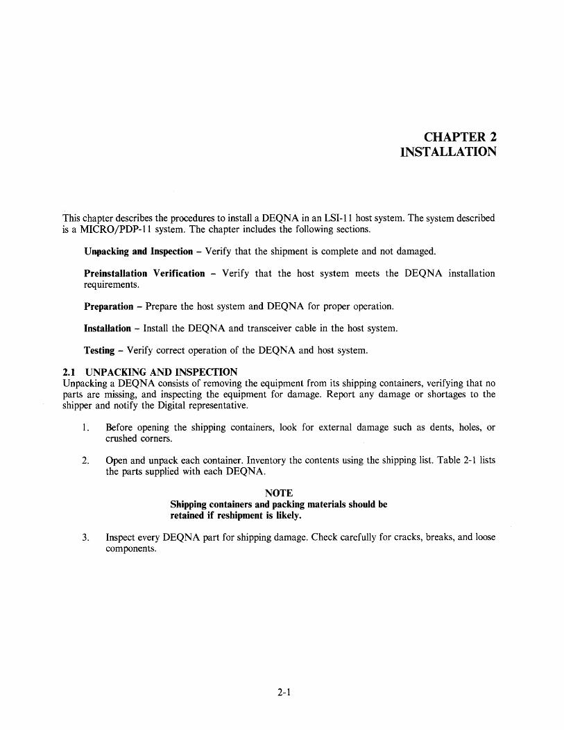
2.1 UNPACKING AND INSPECTION Unpacking a DEQNA consists of removing the equipment from its shipping containers, verifying that no parts are missing, and inspecting the equipment for damage. Report any damage or shortages to the shipper and notify the Digital representative.
1. Before opening the shipping containers, look for external damage such as dents, holes, or crushed corners.
2. Open and unpack each container. Inventory the contents using the shipping list. Table 2-1 lists the parts supplied with each DEQNA.
NOTE Shipping containers and packing materials should be retained if reshipment is likely.
3. Inspect every DEQNA part for shipping damage. Check carefully for cracks, breaks, and loose components.
2-1

Table 2-1 DEQNA Parts List
Part Description
DEQNA Module
Bulkhead Cable Assembly (one of the following):
53.3 cm (21 in) shielded cable/bulkhead (PDP-l 1/23) 30.5 cm (12 in) shielded cable/bulkhead (MICRO/PDP-II) 76.2 cm (30 in) shielded cable/bulkhead (PDP-II/23-PLUS) 3.048 m (10 ft) shielded cable (general use*)
DEQNA User's Guide
DEQNA PDP-II Diagnostic Set (Field Diagnostic Resident Code)
* Non-FCC compliant installations
2.2 PREINSTALLATION VERIFICATION
Designation
M7504
CK-DEQNA-KA CK-DEQNA-KB CK-DEQNA-KC CK-DEQNA-KD
EK-DEQNA-UG-OOI
CIQN DAO AC-T6I2A-MC
To verify that the DEQNA can be correctly installed in the host system, the following requirements and constraints must be met.
2.2.1 Host Boot/Diagnostic ROMs Verify that the correct boot/diagnostic ROMs are installed in the host CPU. That is, the host CPU must be capable of loading the extended bootstrap code from the DEQNA BD ROM.
2.2.2 Backplane Requirements The DEQNA requires one dual LSI-II module slot configured for Q22-Bus (that is, extended LSI-II bus) operation for highest performance.
2.2.3 Bus Latency Constraints To get the best performance and avoid losing packets, the DEQNA should be the highest priority device on the Q-Bus, that is, the DMA device nearest to the CPU. When two DEQNAs are installed, a blockmode memory is required, if high ETHERNET traffic rates are to be handled. The following is a recommended module installation.
Processor Memory DEQNA I DEQNA 2 / Other Others
2.2.4 Loading Requirements
Slot I Slot 2 Slot 3 Slot 4 Slots 5 - 8
Check that system loading capacity is not exceeded by installing the DEQNA. Table 2-2 shows the DEQNA Q-Bus loading and Table 2-3 shows the DEQNA and transceiver power requirements.
CAUTION Power supply voltages should be checked before and after installation to verify the absence of overloading and overvoltage conditions.
2-2

Table 2-2 DEQNA Q-Bus Loading
Module Q-Bus dc Loads Q-Bus ac Loads
M7504 0.5 2.2
Table 2-3 DEQNA Power Requirements
Voltage Rating (Typical Values)
+5 ± 0.25 V @ 3.5 A
+ 12 ± 0.60 V @ 0.5 A (for Transceiver)
Logic Reference
Transceiver Return
Typical Current
3.5 A
0.5 A
Maximum Current
5.0 A
*
Backplane Pins
AA2, BA2. BVI
BD2
All, AMI, ATI, AC2, BlI, BMI, BC2
BTl
* At power-up or powered-up connect, transceiver surge current at the power connection is high enough to currentlimit and power-fail some power supplies. The DEQNA does not contain power supply surge protection; it must be provided elsewhere if required by the system configuration.
2.3 PREPARATION Prepare the host and DEQNA for installation using the following procedure.
2.3.1 Backplane
1. Turn system power off, and unplug the ac power cord from the wall socket.
a. Remove the rear plastic cover of the system unit by holding each end and pulling the cover toward you. (Does not apply to rack-mounted units.)
b. Open the patch and filter panel assembly (also called the system I/O panel, the distribution panel, and the bulkhead). (See Figure 2-1.) Loosen the two screws at the end of the panel opposite the hinge, and swing the panel open.
c. If necessary, reconfigure the system to accept the DEQNA in the appropriate backplane slot. (See Paragraph 2.2.3.) Remove or relocate M7272 Grant Continuity cards as necessary.
2. Plug the ac power cord into the wall socket, and turn system power on.
3. Measure the backplane voltages. They should be within the tolerances listed in Table 2-3.
4. Turn system power off and unplug the ac power cord from the wall socket.
2-3

UNUSED OPTION PANELS
5O-PIN CONNECTOR EXPANSION SLOTS OR DEQNA PANEL
o
MA-12453
Figure 2-1 Patch and Filter Panel Assembly
2.3.2 M7504 Module The DEQNA module, M7504, is configured with three jumpers, WI through W3, installed during manufacture. (See Figure 2-2 and Table 2-4.) The disposition of these jumpers is described in the following paragraphs.
2.3.2.1 Device Address Assignment (WI) - The DEQNA 110 page addresses are 17774440 (first DEQNA) and 17774460 (second DEQNA). If two DEQNAs are to be installed, move jumper WI onto the second DEQNA position, to set its 110 page address to 17774460. (See Chapter 4, Paragraph 4.2.)
2.3.2.2 Bus Request Holdoff Timer (W2) - Jumper W2 provides "fair" access to all DMA devices using the Q-Bus (see Chapter 1, Paragraph 1.4.2), and should not be added, except for unusual requirements (not supplied).
2.3.2.3 Sanity Timer (W3) - If not removed, jumper W3 disables the sanity timer at initialization. If removed, jumper W3 enables the sanity timer at initialization. (See Chapter 1, Paragraph 1.3.6.)
2.3.3 Patch and Filter Panel Assembly The transceiver cable bulkhead assembly will be installed in an unused option panel location on the system 110 panel. (See Figure 2-1.) Remove the option panel by removing the four screws. Save the screws.
2.4 INSTALLATION Install and cable the DEQNA and the bulkhead assembly as follows. (See Figure 2-3.)
1. Slide the M7504 module into the card guides with the component side nearest to the processor module. Do not insert the module all the way into the slot at this time.
2. Insert the transceiver cable assembly into the system 110 panel with the four screws saved when the blank panel was removed.
3. Connect the keyed cable of the bulkhead assembly to the module.
4. Slide the M7504 all the way into the card slot.
2-4

Jumper
WI W2 W3
STATION ADDRESS PROM
W2
LEOs TEST POINT 1
~~~tr£"""~ ... ~ .. LWl ~ BOOT/DIAG ~ I ....... "." .. ~ DO W3
C]
MA-12440
Figure 2-2 M7054 Showing Jumpers, LEDs, Transceiver Cable Connector, Station Address PROM, and Boot/Diag PROM
Table 2-4 DEQNA Jumper Functions
Out/ Function In 2nd Position
I/O Page Address 17774440 17774460 BDMR Holdoff Timer No Delay 5 J,LS Delay Sanity Timer at Initialization Disabled Enabled
2-5

2.5 TESTING Perform the following tests to verify that the DEQNA and host system are operating correctly.
NOTE In order to successfully run the citizenship (CQ) diagnostic tests, either an operational ETHERNET transceiver with cable must be connected to the DEQNA9 or the loopback connector must be connected to the bulkhead assembly.
2.5.1 Post-Installation Power Checks Perform the following tests on the backplane slot that contains the M7504 module.
1. Plug the ac power cord into the wall socket, and turn the system power on.
2. Measure the backplane voltages. They should be within the tolerances listed in Table 2-3.
3. Turn system power off.
2.5.2 Light-Emitting Diode (LED) Checks The M7504 module includes three LEDs which indicate the operational status of the DEQNA. (See Figure 2-2.) Table 2-5 defines the LED indications.
Table 2-5 DEQNA LED Indications
LED 1 2 3 Definition
OFF OFF OFF The DEQNA passed all citizenship tests. Transceiver, ETHERNET, or cable error. DEQNA internal error.
OFF OFF ON OFF ON ON ON ON ON Cannot upload BD ROM contents, the bootstrap has not yet executed, or
the first set-up packet pre fill has failed.
1. Connect either an ETHERNET transceiver with cable or a loopback connector to the transceiver cable connector on the patch and filter panel assembly. (See Figure 2-1.)
2. Turn system power on. All three LEDs on the M7504 module should be on within one second.
3. Boot the system from the DEQNA. Note that new CPU PROMs (with code for booting from the DEQNA) must have been installed. The LEDs should be turned off, one at a time, until no LEDs are on.
2-6

2.5.3 Diagnostic Acceptance Procedure
1. Run the field functional test. (See Chapter 3, Paragraph 3.2.3.)
2. Turn system power off.
3. Close and fasten the patch and filter panel assembly.
4. If a loopback test transceiver was used, disconnect it.
5. Replace the rear plastic cover on the system unit. (Does not apply to rack-mounted units.)
6. If not already connected, connect the system to an installed ETHERNET transceiver.
Installation is now complete.
2-7


This chapter describes servicing the DEQNA. It includes the following sections.
CHAPTER 3 SERVICE
Maintenance Philosophy - Defines the DEQNA Field Replaceable Units (FRUs).
Diagnostics - Describes the DEQNA diagnostic programs.
Corrective Maintenance - Describes the corrective maintenance procedures for the DEQNA.
3.1 MAINTENANCE PHILOSOPHY Corrective maintenance is performed by FRU replacement. The following are the field replaceable units.
1. M7504 module 2. Bulkhead cable assembly 3. Bulkhead fuse 4. Ampere filter (if used)
3.2 DIAGNOSTICS
NOTE When the module is replaced, the user may be able to retain the original ETHERNET address by swapping the station address PROM from the replaced module to the new module, and verifying with diagnostics that the original station address PROM works in the new module.
The DEQNA diagnostics include software to boot the DEQNA, tests to ensure that the module is working correctly, and tests to isolate faults.
3.2.1 Extended Primary Bootstrap (EPB) The DEQNA is loaded, or booted, in a way that is similar to mass storage device booting. Host primary boot code passes control to the Extended Primary Bootstrap (EPB) code (loaded from the BD ROM), which continues the bootstrap process by loading the complete contents of the BD ROM into host memory. When the load is complete, the DEQNA citizenship test is run before the DEQNA is allowed to access the ETHERNET.
If the citizenship test is passed, the bootstrap process continues. Control is transferred to either the DECnet bootstrap, which is part of the Maintenance Operation Protocol (MOP) code loaded from the BD ROM, or to an address in host memory.
3-1

If the DEQNA fails the citizenship test, the EPB code attempts to halt the CPU, without attempting to boot DEC net or transferring control to a user's program. The LEDs on the DEQNA help to indicate the nature of the failure.
In general, the boot sequence is as follows.
1. Load the first 512 bytes of BD ROM. This is the EPB code.
2. Verify descriptor status and the CSR.
3. In the host, set up registers RO and Rl, and location 12 (octal) of main memory (see next step). Continue.
4. If a failure is detected, examine location 12 (octal) of main memory. If location 12 is zero, halt the EPB. If location 12 is non-zero, transfer control to the address contained in location 12.
5. Load the remaining bytes of the BD ROM into host memory.
6. Verify the BD ROM data transfer using the ROM checksum.
7. The host executes the citizenship test.
8. If the citizenship test fails, return control to the EPB and halt.
9. If the citizenship test passes, transfer control (as determined by the value in host register RO) to either:
a. The MOP code to boot DECnet. This code continuously attempts to boot DEC net until successful or until stopped by the host.
b. User defined code.
3.2.2 Citizenship Test (CQ) The DEQNA Citizenship Test (CQ) is a series of diagnostic test routines that determine if the DEQNA is operating correctly and can access the ETHERNET or is faulty and requires further diagnosis. Test results are indicated by the LEDs on the DEQNA and are returned in host register RO, where they are accessible to software. The CQ test uses internal loopback, internal extended loopback, and external loopback modes, and requires the DEQNA and an H4000 transceiver (or equivalent); connection to the ETHERNET is not required. Prior to executing the tests, CQ turns off the sanity timer. Upon completion of the tests, it turns the sanity timer on if jumper W3 is removed (timer enabled), or leaves the timer off if jumper W3 is in place (timer disabled).
The CQ test is a free-standing subroutine and can be called by other software. For example, during network boot, CQ can determine if the node should be allowed to proceed from the initialized state to either a functional state or nonfunctional state. If a fault exists, MOP code can call CQ to determine if other DEQNA diagnostics or network-level diagnostics are required for fault isolation.
3.2.2.1 Test Descriptions - The tests are described in the following list. Corresponding bit numbers in host register RO are given for each possible error reported by the test. An error summary is given in Paragraph 3.2.2.2.
3-2

1. Station Address Verification - The default physical address is verified and copied from the station address ROM into a test packet for later use. If this test fails, testing continues until the final external loopback test or another test failure occurs. Possible errors are:
RO Bit
00 00 00 10
Description
Station address is all zero bits. Station address is all one bits. Station address is not a valid DEQNA address. Bus time-out or nonexistent memory error.
2. Device Interrupt and Nonexistent Memory - After interrupts are enabled, a transmit buffer descriptor chained to a nonexistent memory location is sent to the Unit Under Test (UUT), that is, one of the two possible DEQNAs. The UUT should generate a transmit interrupt with the CSR NI bit (bit 02) set. Possible errors are:
RO Bit
11 11 11
Description
No interrupt occurred. Interrupt occurred prematurely. Wrong interrupt occurred.
3. Set-up Mode and Receive FIFO Processing - A series of set-up packets is transmitted to the UUT, to test "stuck-at" faults. The packets contain repeating test patterns which are varied to test each target address RAM byte with all patterns. The set-up packets are echoed into the receive FIFO and verified. The set-up packet lengths are such that all the receive FIFO bytes receive each of the four basic patterns, as the operation is repeated. Possible errors are:
RO Bit
12,01 09,12,01 14,12,01
Description
Target address echoed data check. Set-up packet operation time-out. Set-up packet operation status check.
4. Internal Loopback and Address Filter - A target address set-up packet with "walking" bit pattern is generated and set-up in the UUT. Then, two internalloopback packets are generated and transmitted for each address in the pattern. The first packet is addressed to the complemented target address (not in the pattern), and must be correctly transmitted and received as a runt. (See Chapter 1, Paragraph 1.3.7.) The second packet is addressed to a target address in the pattern, and must be correctly transmitted and received.
The test is repeated with the walking bit = 1 and the walking bit = 0. Possible errors are:
RO Bit
02 09,02 09,02 12,02 14,02 14,02 09,12,02 14,12,02
Description
Transmitted and received and data compare check. Runt packet transmit and receive operation time-out. Valid packet transmit and receive operation time-out. Target address echoed data check. Runt packet transmit and receive operation status check. Valid packet transmit and receive operation status check. Set-up packet operation time-out. Set-up packet operation status check.
3-3

5. Internal Extended Loopback and Protocol - The UUT is put in internal extended loopback mode and packets of increasing length are circulated through the transmit buffer (prefill RAM) and the receive FIFO. The packet bit patterns are intended to uncover "stuck-at" conditions and faults in buffer and FIFO processing. The received packets are verified to be sure that data was correctly transferred. The packet lengths increase in 3-byte increments, from the minimum ETHERNET packet size to beyond the maximum size. The test completes when the UUT detects the expected long packet. Possible errors are:
RO Bit
03 03 09,03 14,03
Description
Long packet not detected via device transmit status. Internal extended loopback transmit/receive data compare check. Test packet transmit or receive operation timed-out. General operation status, check, long packet not detected.
6. DMA Q-Bus Interface Processing - An internal extended loopback packet based on a transmit BDL with contiguous and chained unaligned buffer segments is transmitted using the default physical address. This packet is received and verified. Possible errors are:
RO Bit
04 09,04 14,04
Description
DMA Q-Bus interface transmit (scatter/gather) data check. Transmit (special) and receive operation time-out. Receive or transmit operation status check.
7. Transceiver Operational and Status - A set-up packet with the physical address of the UUT is generated and sent to the target address RAM. The packet also turns off LED 2. The CSR carrier bit (bit 13) is monitored to be sure it is cleared; or, if it is set, that it is cleared within approximately 100 microseconds. Possible errors are:
RO Bit
12 09,12 14,12 15
Description
Target address packet with LED command echoed data check. Set-up packet operation time-out. Set-up packet operation status check. CSR carrier bit on too long.
8. External Loopback and ETHERNET Protocol - This test is executed only if no other errors have been detected.
The physical address of the UUT is assumed to be in the target address RAM. A minimum size ETHERNET packet, with a descending-integers data pattern and addressed to the UUT, is transmitted and received using externalloopback. Next, a maximum size ETHERNET packet with the same characteristics is generated and sent to the UUT. Both packets test ETHERNET protocol processing, and the maximum size packet also tests the transmit buffer.
3-4

Packets which "go on the wire" are compatible with loopback test packets, have the protocol type set to loopback, and other fields set such that testers ignore these packets. The destination (and source) address of the loopback packet is the assigned ETHERNET station address of the UUT (that is, its default physical address). Possible errors are:
RO Bit
15 05 09,05 14,05
Description
Externalloopback over ETHERNET cable is not operational. Minimum or maximum sized packet data compare check. Minimum/maximum packet operation time-out. Minimum/maximum packet operation status check.
3.2.2.2 Test Results - The CQ test will either execute successfully or fail. The two possibilities are described below.
1. If the CQ test executes successfully, the value of host register RO is zero and the DEQNA is setup as follows.
a. All three LEDs are off.
b. All 14 target addresses are set to the physical address from the station address ROM.
c. The sanity timer is set to its default interval (4 minutes) and disabled or enabled, according to the disposition of the sanity timer jumper (W3).
d. Promiscuous and all multicast address modes are off.
e. The DEQNA has been reset:
Receive is disabled Transmit is disabled
2. If the CQ test fails, the LED indications will display the following error codes.
LED 1
OFF OFF ON
2
OFF ON ON
3
ON ON ON
Definition
Transceiver or ETHERNET error DEQNA internal error Cannot upload BD ROM contents or the first set-up packet prefill failed.
If the DEQNA passed the tests, all the LEDs are off.
3-5

The bits in register RO indicate the test that failed. If bit 15 is the only bit set, the DEQNA passed all the CQ tests except those which require a connected transceiver. The errors/bits are defined as follows (multiple bits can be set).
Error/ Bit
15
14
13
12
11
10
09
08
Error Definition and Source(s)
External loopback not operational (Tests 7 and 8)
ETHERNET not operational H4000 not operational (blown fuse, disconnected)
Operation completion status check (all tests)
CSR status after final reset not nominal CSR status after transmit and/or receive not nominal Receive descriptor flags and status word 1 not nominal Received byte length check Transmit descriptor flags and status word 1 not nominal TDR value = 0
Sanity timer interrupt (general error)
Power failed during test Unexpected sanity timer interrupt
Set-up packet or target address echo check (all tests)
Set-up packet transmit time-out Transmit status not nominal Set-up packet receive time-out Receive status not nominal Echoed data not identical to transmitted data Extra word at end of set-up packet not nominal
Spurious or missing device interrupt (general error)
Expected device interrupt not detected Device did not detect nonexistent memory (NXM) bus state 18-bit or 22-bit addressing failure Unexpected DEQNA device interrupt
Bus time-out or NXM interrupt (general error)
I/O page not accessible for read or write Cannot read station address ROM Test code attempted to access nonexistent memory
Device operation time-out (all tests)
Unit under test failed to complete a transmit and/or receive in time
Undefined
3-6

07
06
05
04
03
02
01
00
Undefined
Undefined
ETHERNET externalloopback test check (Test 8)
ETHERNET protocol processing check ETHERNET minimum valid length processing check ETHERNET maximum valid length processing check
DMA interface processing check (Test 6)
DMA odd/even length and address processing check Multielement transmit descriptor processing check Chained transmit descriptor processing check
Internal extended loopback transmit buffer data check (Test 5)
ETHERNET protocol processing check Transmit buffer memory malfunction Packet size processing error (protocol error)
Station address compare test check (Test 4)
Address filter logic passing all addresses Address filter logic not passing expected addresses
Station address/receive FIFO processing check (Test 3)
Target address RAM malfunction Packets not properly stored in receive FIFO Receive FIFO memory malfunction
Invalid ETHERNET station address (Test 1)
I/O page register read failure (see also bit 10) Unit under test is not a DEQNA (M7504) Station address ROM malfunction Invalid DEQNA address
3.2.3 Field Functional Test The Field Functional Diagnostic Program (ZQNA) tests the DEQNA in Q18 or Q22-Bus systems. It attempts to isolate faults to the following FRUs.
1. DEQNA 2. Bulkhead assembly 3. Bulkhead assembly fuse 4. Transceiver cable 5. Transceiver
3-7

The ZQNA also attempts to localize faults to the failing DEQNA functional area(s).
1. Q-Bus DMA Transfer Controller (QDTC) 2. Receive First-In/First-Out (FIFO) and transmit buffer memory 3. ETHERNET Protocol Processor (EPP) 4. Manchester Encoder/Decoder (ED/DE)
Tests are executed under the supervision of the XXDP /DRS, and controlled by an operator from a console (hard copy or video). For DRS commands, see Appendix C, Paragraph C.4, or the XXDP+ User's Manual.
Note that the ZQNA diagnostic program is not an ETHERNET network exerciser. The ZQNA assures that the module can execute ETHERNET protocol and that valid network traffic can be transmitted and that valid network traffic can be received. The network exerciser (see Appendix C) provides a higher level of testing.
3.2.3.1 Configuration and Set-Up - The DEQNA is tested in allioopback modes. The ZQNA tests the DEQNA in internalloopback and internal extended loopback modes, with or without an externalloopback connector or transceiver connected (that is, a connected transceiver or the'loopback connector does not have to be unplugged). Externalloopback mode is used with a connected transceiver or externalloopback connector. Executing ZQNA using external loopback mode in a system connected to a "live" ETHERNET does not disrupt the ETHERNET. Alternatively, externalloopback mode can be used with a terminated transceiver that is not attached to a network cable.
The functional areas tested in each loopback mode are shown in Table 3-l.
Table 3-1 ZQNA Tested Functional Areas
Loopback Mode
Functional Area * Setup Internal
Q-Bus X X
QDTC X X
FIFO X X
ED/DE X X
EPP X X
EPP Address Checking Logic X
Transcei ver and Cables
*Q-Bus QDTC FIFO EPP ED/DE
= Processor data bus = Q-Bus DMA transfer controller = Transmit and receive memory buffers = Ethernet protocol processor = Manchester encoder/decoder
3-8
Internal Extended
X
X
X
X
External
X
X
X
X
X
X

The sanity timer jumper (W3) must be removed to enable the timer before executing the sanity timer test (described in item 21 of the following paragraph). When sanity timer testing is complete, the jumper should be restored to its position before the test.
3.2.3.2 Test Descriptions -
1. Nonexistent I/O Page Register Test - This test verifies that all the device registers residing in the I/O page can be accessed without forcing a nonexistent memory (NXM) interrupt.
Hardware Tested: Q-Bus to DEQNA port register interface.
2. CSR Bit Test - This test verifies that the CSR register static bits can be set and cleared as specified. The host writes data patterns to the CSR and reads them back, checking for static (stuck at 1 or 0) faults.
Hardware Tested: Q-Bus to DEQNA port register interface.
3. ETHERNET Station Address Verify Test - This test verifies that the ETHERNET station address PROM can be correctly read and loaded to host memory. The ETHERNET station address is read from the PROM and a checksum is computed; this checksum is then compared to the checksum stored in the PROM. The ETHERNET station address is always printed out on the console in the ETHERNET standard format. If the address is not correct, the error is recorded and an appropriate error message is printed out on the console.
Hardware Tested: Station address PROM and Q-Bus to DEQNA port register interface.
4. Interrupt Vector Address Test - This test verifies that all bits of the vector address register can be set and cleared as specified. The host writes data patterns to the register and reads them back, checking for static (stuck at 1 or 0) faults. Note that only bits <09:02> of the interrupt vector address register are valid; the rest are read as zero. Hardware Tested: DEQNA vector address register and port registers.
5. Boot/Diagnostic ROM Checksum Test - This test verifies that the contents of the BD ROM can be correctly loaded into host memory. The ROM data is read and a checksum computed; this checksum is then compared to the checksum stored in the last word location of the BD ROM.
Hardware Tested: Q-Bus DMA interface, 8051 microprocessor, 8051 ROM, CSR, and receive FIFO.
6. Interrupt Sanity Test - This test verifies that the DEQNA interrupts the processor at only the expected level (4), not any other level.
Hardware Tested: Q-Bus QDIC interface, CSR, Q-Bus time-out logic, and QDTC interrupt logic.
7. ETHERNET Carrier Sense Test - This test verifies that the DEQNA can transmit loopback packets. The DEQNA must be connected to the transceiver to run this test successfully.
Hardware Tested: Carrier sense circuitry and ED/DE chip.
3-9

8. Station Address RAM Test - This test verifies that the station address RAM has no static faults. The host writes and then reads data patterns to all of the addressable RAM (572 bytes). Write and read data patterns are compared to check for errors. The test continues until all the data patterns are exhausted.
Hardware Tested: Station address RAM, Q-Bus QTDC interface, CSR bit 00 (Receiver Enable), and part of receive and transmit FIFO.
9. Promiscuous Station Address Test - This test verifies that DEQNA promiscuous addressing mode functions as specified. The test uses bit patterns and addresses within and out of the set-up address range, to assure that there is true promiscuity.
Hardware Tested: Promiscuous addressing mode logic.
10. Transmit and Receive FIFO Memory Test - This test verifies that link memory (receive FIFO and transmit buffer) has no static faults. The host writes and then reads a sequence of data patterns to all of the link memory. The received pattern is compared to the transmitted pattern to check for errors. The test continues until all the data patterns are exhausted.
Hardware Tested: Transmit buffer address logic, transmit buffer memory, receive FIFO address logic, and receive FIFO memory.
11. Packet Length Test - This test verifies that DEQNA can transmit and receive variable length packets (equal to or greater than 60 bytes and equal to or less than 1514 bytes without the CRC) without losing any data in the process. This test also verifies that the ninth bit of the FIFO memory is not static (stuck at 1 or 0).
Hardware Tested: Transmit and receive RAM.
12. Descriptor List Address and Interrupt Test - This test verifies that transmit and receive list invalid bits (CSR bits 04 and 05) can be set and reset as specified; and that both transmit and receive descriptor list addresses in the I/O page have to be valid to successfully loopback a packet.
Hardware Tested: Q-Bus to QTDC interface - valid and invalid host memory address processing; CSR register bits 02 (NXM Interrupt), 06 (Interrupt Enable), and 05 (Receive List Invalid).
13. Buffer Address and Interrupt Test - This test verifies that the buffer address in the descriptor list has to be valid in order to loopback a packet. A nonexistent memory interrupt is generated if an invalid buffer address is specified in the descriptor list.
Hardware Tested: Q-Bus to QTDC interface - valid and invalid host memory address processing; CSR register bits 02 (NXM Interrupt) and 06 (Interrupt Enable).
14. DMA Timing Test - This test uses a chained loopback packet, to verify that the DMA transfer completes within "n" milliseconds. The number of milliseconds, "n," depends on the operator's response to the prompt:
SYSTEM HAS BLOCK MODE MEMORY (L)?
3-10

Hardware Tested: Internal extended loopback, transmit status - last descriptor in chain (bit 15), and receive status - last descriptor in chain (bit 15), and error summary (bit 14).
15. Long Packet Test - This test verifies that DEQNA can detect long packets (1600 bytes or more, with the CRC) when transmitted in internal extended loopback mode.
Hardware Tested: Receive status - error summary (long packet - bit 14).
16. Odd Packet Test - This test uses chained and unchained descriptor lists to verify that the DEQNA can transmit and receive packets of odd length, and packets that start and/or end on odd addresses.
Hardware Tested: CSR bits 04 (Transmit List Invalid) and 05 (Receive List Innvalid), and transmit descriptor bits (transmit buffer ends on odd byte and transmit buffer ends on even byte).
17. Station Address Test - This test verifies that DEQNA accepts only packets with legitimate multicast and nonmulticast addresses, and discards those with illegitimate multicast and non multicast addresses.
Hardware Tested: Address filter circuitry.
18. All Multicast Station Address Test - This test verifies that the DEQNA recognizes the allmulticast addresses of the node and discards loopback packets with nonenabled addresses.
Hardware Tested: All-multicast addressing, 8051 microprocessor, and address filter circuitry.
19. Runt Packet Test - This test verifies that the DEQNA can detect runt packets in FIFO.
Hardware Tested: EPP, address filter circuitry.
20. FIFO Overflow Test - This test verifies that the ETHERNET protocol processor can detect a receive FIFO overflow condition.
Hardware Tested: Receive status word 1, bits 14 (Error), 12 (Discard), and 00 (Overflow); and EDLC byte FIFO.
21. Sanity Timer Test - This test verifies that the sanity timer times out after a pre-set time-out period (supplied by the operator). -
Hardware Tested: Sanity timer logic.
3-11

3.2.3.3 Operation - Tests are executed under the supervision of the XXDP /DRS. For DRS commands see Appendix C, Paragraph C.4, or the XXDP+ User's Manual. ZQNA - specific prompts and responses can be divided into three categories: start-up procedure (XXDP+), hardware questions, and software questions. These are described below.
Start-Up Procedure (XXDP+) - To start-up this program, use the following procedure.
1. Boot XXDP+
2. Give the date
3. Type: R NAME (where NAME is the name of the BIN file for this program)
4. Type: START
5. Type: Y (yes) in response to the CHANGE HW prompt
6. Answer all the hardware questions
7. Type: Y (yes) in response to the CHANGE SW prompt
8. Answer all the software questions
This procedure uses only the defaults for flags and software parameters.
Hardware Questions - When a diagnostic is started, the DRS requests hardware information with the prompt:
CHANGE HW (L) ?
Y (yes) is the correct response after a START command, unless hardware information has been preloaded using the Set-up Utility. (See the XXDP+ User's Manual, Chapter 6.) When it receives a Y response, the DRS requests the number of units. It then requests the following information for each unit.
# OF DEVICES (D) ?
The response is the number of units to be tested (no default). This response determines the number of times the following information is requested. One device must be specified.
DEQNA I/O PAGE ADR (0) 174440?
The response is the address of the I/O page register assigned for one of the DEQNA devices. The legal I/O page addresses are 174440 and 174460.
INTERRUPT VECTOR ADR (0) 700 ?
The response is the DEQNA interrupt vector address. The interrupt vector address is 700 (octal) for the DEQNA at I/O page address 174440, and 704 (octal) for the DEQNA at I/O page address 174460.
Software Questions - After the hardware questions are answered, or following a RESTART or CONTINUE command, the DRS requests software parameters. These parameters govern some diagnostic-specific operation modes. The prompt is:
CHANGE SW (L) ?
3-12

The response is Y (yes) to change any parameters. Three software questions follow. The first question is:
DO YOU WANT TO TEST SANITY TIMER (L)?
If the response is Y (yes), the DRS displays two additional prompts:
IS SANITY TIMER JUMPER ENABLED/CUT (L)?
The response is Y (yes) if the sanity timer jumper is removed; otherwise remove the jumper and then type Y.
SANITY TIMER TIMEOUT VALUE (O)?
The response is a decimal time-out value (between 0 and 7) that represents the time-out period, according to Table 3-2.
The second question is:
EXECUTE TESTS IN INTERNAL/EXTENDED LOOPBACK MODE (L)?
A Y (yes) response causes test to execute in internal and internal extended loopback modes. A N (no) response causes tests to execute in internal and external loopback modes.
The third question is:
SYSTEM HAS BLOCK-MODE MEMORY (L)?
The response is Y (yes) if the system has block-mode memory and N if it has non-block-mode memory.
Table 3-2 Sanity Timer Time-Out Values
Time-Out Value
o 1 2 3 4 5 6 7
Time-Out Period
1/4 second 1 second 4 seconds 16 seconds 1 minute 4 minutes 16 minutes 64 minutes
3-13

3.2.3.4 Error Reporting - A diagnostic can issue general and specific types of error messages.
General error messages are always printed unless the IBE and/or IER flag is set, and have the format shown in Figure 3-1.
where:
Figure 3-1 General Error Message Format
NAME Diagnostic name ER--TYPE= Error type (all errors are hard errors) ER--NO Error number UNIT_NO= 0 TEST_NO= Test and sub test where error occurred PC--ADDR= Program counter contents
MR-12B03
General error messages may include two sublevels: basic error messages and extended error messages.
Basic error messages are printed after the associated general error message, and contain some additional information about the error. They are always printed unless one or more DRS error flags (IBE, IXE, IER) are set.
Extended error messages are printed after the associated general error message and any associated basic error messages. Extended error messages contain additional error information, such as register contents or good/bad data. They are always printed unless either the IXE or IER flag (or both) is set. The format of a typical extended error message is shown in Figure 3-2.
TRANSMIT DESCRIPTOR LIST
FLAG WORD LOW-ORDER ADDRESS BITS HIGH-ORDER ADDRESS BITS PACKET LENGTH (BYTE) STATUS WORD 1 STATUS WORD 2
RECEIVE DESCRIPTOR LIST
FLAG WORD LOW-ORDER ADDRESS BITS HIGH-ORDER ADDRESS BITS PACKET LENGTH (BYTE) STATUS WORD 1 STATUS WORD 2
MR-12B04
Figure 3-2 Typical Extended Error Message Format
3-14

Specific error messages will be defined as needed. The following are possible error messages.
Device fatal error messages:
CSR REGISTER FAILED TO RESPOND NO INTERRUPT FROM DEQNA
Return status messages.
TRANSMIT STATUS ERROR RECEIVE STATUS ERROR CSR STATUS ERROR
3.2.4 DEQNA DEC/XII Exerciser The DEQNA DEC/XII Exerciser, also called the QNA Option Module (QNA OPMOD), exercises one DEQNA at maximum activity rates in order to provoke noise, timing, and logical interaction failures. It transmits and receives random length packets (using either 18- or 22-bit physical address space). The DEQNA transmits and receives the same packet.
One pass of the exerciser consists of 1000 iterations of transmitting a packet, receiving a packet, and comparing the contents of the transmit packet to the receive packet. Packet length is random for each iteration. Transmit and receive status words and CSR status are all checked for correct contents.
The DEQNA is dropped from further testing if any of the following occurs.
1. The DEQNA does not reset properly. 2. The CSR and/or the receive and/or transmit status word(s) are in error. 3. A hard error occurs. -4. A transmit and/or receive interrupt is not generated. 5. The transceiver is disconnected while in external loopback mode.
Internal extended loopback mode is the default mode of operation.
3.2.4.1 Configuration and Set-Up - It is assumed that, prior to running this exerciser, both the DEQNA citizenship test and field functional test have been successfully run. The default parameters are:
Device address: 17774440 Interrupt Vector: 700 BR level: 5 Number of devices: 1
The holdoff timer jumper (W2) must be removed and the sanity timer jumper (W3) must be in place (both as shipped).
To run the exerciser in externalloopback, the DEQNA under test must be connected to the transceiver or the externalloopback connector must be connected.
Software Register 1 (SRI) bit 0 and 1 options are described in Table 3-3.
3-15

Bit Value
o o
o
o
Table 3-3 DEQNA DEC/XII Exerciser Software Register Bits
Description
Exerciser runs in internal extended loopback mode (default). Transceiver is not needed.
Exerciser runs in external loopback mode. Transceiver or external loopback connector is required.
Print error messages.
Do not print error messages.
3.2.4.2 Commands - To set externalloopback mode, type the following commands.
MDD QNAAO 16<RETURN> 1 <RETURN>
To test a DEQNA in the second slot (address 17774460), type the following commands after the exerciser has been loaded.
MOD QNAAO 6<RETURN> 174460<LINE FEED> 704<RETURN>
For additional information refer to the DEC/X]] User's Manual, CWQUACO.
3.2.4.3 Error Messages - Error messages print the contents of the DEQNA descriptor lists in the order shown in Figure 3-3,
DEONA - "ERROR MESSAGE"
TRANSMIT DESCRIPTOR LIST
FLAG WORD LOW-ORDER ADDRESS BITS HIGH-ORDER ADDRESS BITS PACKET LENGTH STATUS WORD 1 STATUS WORD 2
DEONA CSR REGISTER DEONA I/O PAGE ADDRESS
RECEIVE DESCRIPTOR LIST
FLAG WORD LOW-ORDER ADDRESS BITS HIGH-ORDER ADDRESS BITS PACKET LENGTH STATUS WORD 1 STATUS WORD 2
MA-12805
Figure 3-3 DEQNA DEC/XII Exerciser Error Message Format
where "error message" is one of the following.
DEQNA WILL NOT RESET DEQNA - BAD DEQNA STATUS DEQNA - BAD RECEIVE STATUS
3-16

DEQNA - BAD TRANSMIT STATUS DEQNA - XMIT PACKET LENGTH NOT = RCV PACKET LENGTH DEQNA - ATTEMPT TO ACCESS NONEXISTENT MEMORY LOC
Note that transmit and receive descriptor lists are not printed with a DEQNA WILL NOT RESET error message.
3.3 CORRECTIVE MAINTENANCE Replace the failed FRU (see Paragraph 3.1) as indicated by the error code returned by the citizenship test in RO or the error indicated by the field functional test.
3-17


CHAPTER 4 PROGRAMMING·
This chapter contains the information needed to program the DEQNA-KP. It includes detailed descriptions of the formats and functions of the port registers and Buffer Descriptor Lists (BDLs).
4.1 OVERVIEW The DEQNA and host communicate on two levels. First level communications, via I/O page access of port registers, are DEQNA control and status transfers, such as:
1. DEQNA initialization 2. buffer descriptor pointers (that is, starting addresses) 3. DEQNA error status (as opposed to packet error status).
Second level communications, via the transmit BDL and receive BDL, are DMA transfers between the DEQNA and transmit and receive descriptors and data buffers in host memory.
4.2 CONTROL AND STATUS TRANSFERS Each DEQNA is assigned a block of eight I/O page locations (words), used as registers, and available for user programming. The blocks are allocated at I/O page locations 17774440-17774456 and 17774460-17774476 (two DEQNAs are allowed). See Figure 4-1. Six locations (read-only) are used to read the station address PROM. Four locations (write-only) pass the high and low order transmit BDL and receive BDL starting addresses. Note that these same four locations are used in read-only mode as part of the six locations that are used to read the station address PROM (that is, these four locations overlap the previous six read-only locations). The next register (read/write) stores the DEQNA's interrupt vector. The final register (read/write) is the DEQNA's control and status register (CSR). All the registers are wordaddressable only. A detailed description follows.
4-1

STATION ADDRESS PROM (RO)
15 08 07 00 177744
r---r-~~I --,.~ ----r-: --'--"""""'--'---'----'r---T'": -----r-: -.-~--r---1140 (60)
~~ __ ~ __ ~I_R_ES_E~~_V_ED~ __ ~ __ ~ __ ~ __ ~ __ ~ __ ~. __ ~. __ ~ __ ~ __ ~~ ~~~~~~H
RECEIVE SDL START ADDRESS (WO)
15 05 00
15:00 ~I MIMI
I ·
21:16 • 46 (66)
TRANSMIT SDL START ADDRESS (WO)
15 05 00
15:00
~ 1501701
I ·
21:16 • 52 (72)
VECTOR ADDRESS (R/W)
15 10 09 02 00
RR RR 54 (74)
CSR (R/W)
15 13 12 10 09 08 07 06 05 04 03 02 01 00
L.I_R_I ...JI __ RR--,-I_C_A~_O_K~_R_R---,-_S_E --L...._E_L --L...._I L--LI_XI--,-__ I E~I_R_L--L.I_X_L_IL...-S_D--L...._N_I ....II __ S R----L __ RE--I156 1761
RR = RESERVED MR-12441
Figure 4-1 Port Registers
4.2.1 Station Address Registers The station address PROM is read via the lower byte of these six locations. The PROM holds the 6-byte default ETHERNET physical address of the DEQNA, as well as a 2-byte checksum on the 6-byte address. The checksum bytes are read in reverse order from the first two locations, after setting CSR bit 09. See Paragraph 4.2.4, CSR bit 03.)
4.2.2 BDL Starting Address Registers The two transmit and two receive BDL starting address registers point the DEQNA to the start of the appropriate buffer descriptor list. (See Paragraph 4.3.2.2.) The registers are write only and must be written with word instructions. And, the low-order address bits must be written before the high-order address bits; for example, to set-up the transmit list, register 17774450 is written before register 17774452. The DEQNA then starts its functions.
When it gets a receive list address, the DEQNA fetches a buffer descriptor from the receive BDL and starts a DMA transfer from the receive FIFO to the receive buffers, transferring any packets that the EPP
4-2

has passed to the receive FIFO. When it gets a valid transmit list address (and if the DEQNA is not busy with a reception), the QDTC fetches a buffer descriptor from the transmit BDL and begins a DMA transfer from the transmit buffers to the pre fill buffer.
A current list address must be invalidated before a new list address is loaded; if not, the results are unpredictable. (List invalidation is described below.)
4.2.3 Vector Address Register The vector address read/write register holds the DEQNA's interrupt vector address. The vector address is assigned floating with a priority rank of 47. It is configured at system start-up using the floating vector autoconfiguration routines. If the system is being bootstrapped via the DEQNA and is running the DEQNA self-test code, the vector address is temporarily assigned to location 774 (octal), the standard diagnostic vector. The register bit definitions are as follows.
Bit Definition
15: 1 0 rr - Reserved. Read as zero.
09:02 Interrupt Vector Address. Read/write. When the register is read, the value in these bits is such that bits 15:00 are the address of the vector to the DEQNA's interrupt service routine.
01 :00 rr - Reserved. Read as zero.
4.2.4 Control and Status Register (CSR) The primary functions of the CSR are to control the DEQNA's operating mode and report its status. The CSR bit definitions are as follows.
Bit Definition
15 RI - Receive Interrupt Request. Read/write 1. The DEQNA sets this bit when it has received a packet, transferred the packet to the receive buffers, and updated the receive buffers' status in the last buffer's descriptor. The interrupt service routine must clear this bit (write 1 to clear, write 0 has no effect) to allow subsequent interrupt requests (also see bit 06).
14
13
12
11
This bit is cleared by power-up initialization and software reset.
NOTE Interrupts are not queued. If the DEQNA processes multiple messages before the interrupt request bit is cleared, additional interrupts are not requested.
rr - Reserved. Not usable.
CA - Carrier. Read only. This bit reflects the status of the ED's Carrier Sense signal. It can be polled to determine the amount of ETHERNET activity, except when the DEQNA is in an internal loopback mode or the transceiver is disconnected.
OK - Fuse OK. Read only. When set, this bit indicates that the fuse on the transceiver cable bulkhead is supplying voltage. When cleared, this bit indicates the fuse is blown or there is no power to the bulkhead.
rr - Reserved. Not usable.
4-3

10
09
08
07
06
05
SE - Sanity Timer Enable. Read/write. When set and sampled, this bit allows the sanity timer to count to its limit (that is, time-out). When cleared and sampled, this bit both clears and disables the sanity timer. The bit is sampled only after a set-up mode packet of 128 to 255 bytes. (See Paragraphs 4.3.3.2 and 4.3.3.3.)
If the timer is enabled, all transmissions (normal, loopback, or set-up) reset the timer and leave it enabled. If the count reaches its limit, Q-Bus DCOK is negated for approximately 7.2 microseconds, causing the host to reboot itself.
The timer is cleared and disabled at power-up if the timer jumper (W3) is in place. If the timer jumper is removed, the timer is enabled at power-up. The default time-out period is 4 minutes but can be varied. (Se~ Paragraph 4.3.3.2.)
EL - External Loopback. Read/write. When set, this bit puts the DEQNA into external loopback (ELOOP) mode. Asserting both this bit and ILOOP (bit 08) puts the DEQNA into internal extended loop, back mode. (See Chapter 1, Paragraph 1.3.4.)
Before the DEQNA is put in ELOOP or internal extended loopback mode, the receiver must be disabled (see bit 00, below) and the receive FIFO emptied.
This bit is cleared by power-up initialization and software reset. It has no effect on set-up mode. (See Chapter 1, Paragraph 1.3.4.)
IL -Internal Loopback. Read/write. This bit is active low. When asserted, it puts the DEQNA into internalloopback mode. This bit must also be asserted to put the DEQNA into internal extended loopback mode (see bit 09, above).
This bit is asserted by power-up initialization and software reset to prevent a failed DEQNA from transmitting on the ETHERNET. It has no effect on set-up mode. (See Chapter 1, Paragraph 1.3.4.)
XI - Transmit Interrupt Request. Read/write. When set by the DEQNA, this bit indicates that the DEQNA has transmitted a packet and written the transmit status into the final transmit buffer's descriptor. Software must clear this bit (write 1 to clear; write 0 has no effect) to allow subsequent interrupt requests. Bit 02 must be checked at the same time as this bit to differentiate between a transmit interrupt request (bit 07 set, bit 02 cleared) and an NXM interrupt (bits 07, 05, 04, and 02 set). (See bits 02 and 06.)
This bit is cleared by power-up initialization and software reset.
NOTE Interrupts are not queued. If the DEQNA processes multiple messages before the interrupt request bit is cleared, additional interrupts are not requested.
IE - Interrupt Enable. Read/write. When set, this bit allows the DEQNA to generate an interrupt every time bit 07 or bit 15 goes from cleared to set. This bit is cleared by power-up initialization and software reset. (See Chapter 1, Paragraph 1.3.3.)
RL - Receive List Invalid. Read only. When set, this bit indicates that the receive BDL is empty. This bit is initialized in the set state by power-up initialization and software reset.
4-4

04
03
02
01
00
(See Chapter 1, Paragraph 1.3.3.) Setting bit 02 also sets this bit. It is cleared when the high-order bits of the receive BDL starting address register are loaded; it is subsequently set when the QDTC reaches the end of the receive BDL.
XL - Transmit List Invalid. Read only. When set, this bit indicates that the transmit BDL is empty. This bit is initialized in the set state by power-up initialization and software reset. (See Chapter 1, Paragraph 1.3.3.) Setting bit 02 also sets this bit. It is cleared when the high-order bits of the transmit BDL starting address register are loaded; it is subsequently set when the QDTC reaches the end of the transmit BDL.
BD - Boot/Diagnostic ROM. Read/write. When set, this bit causes one copy of the boot/diagnostic ROM to be loaded into the receive FIFO for subsequent transfer to host memory. Because the ROM is 4 Kbytes, the receive BDL must be set up for a minimum of two 2 Kbyte buffers. Before this function is asserted, the receiver must be disabled (see bit 00) and the Receive FIFO emptied (done best by resetting the DEQNA). This bit must then be asserted for at least 100 microseconds, or until the operation begins (determined by polling the receive buffer's descriptor USING flag). (See Paragraph 4.3.2.1.) If the operation fails (by timing-out), the DEQNA is known to be bad. The ROM contents are validated by a checksum which must be verified at the end of the load. There is no byte offset to the PDP-II bootstrap and diagnostic code.
For normal operation to proceed, software must reset the DEQNA. Because explicit receive status is not reported after the BD ROM data is transferred, and no interrupt is requested, the length of the receive buffers should be exactly 4096 bytes. Completion is then indicated by the USED status in the final buffer's descriptor flags. (See Paragraph 4.3.2.1.)
This bit is cleared by power-up initialization and software reset.
NI - Nonexistent Memory Interrupt. Read only. The DEQNA sets this bit when a time-out occurs during a bus transaction. The setting of this bit also sets bits 04 and 05; that is, both the transmit and receive BDLs are invalidated. The setting of this bit also sets bit 07, causing an interrupt if bit 06, interrupt enable, is set.
This bit is cleared by power-up initialization, software reset, and when bit 07 is cleared.
SR - Software Reset. Read/write. This bit can be set or cleared under program control to initialize the DEQNA. It holds the DEQNA initialized while it is set. This bit is cleared by power-up initialization; however power-up initialization also holds the DEQNA initialized.
This bit and power-up initialization clear bits 00, 02, 03, 06, 07, 09, 10 and 15; and set bits 04, OS, and 08 (low).
RE - Receiver Enable. Read/write. When low (cleared), this bit disables the EPP receiver in the EDLC. It does not disrupt a reception in progress and has no effect on any messages queued in the receive FIFO. Its primary function is to synchronize certain other DEQNA functions with ETHERNET packet reception (see bits 03 and 09). Transmit activity is regulated by software via the transmit BDL.
This bit is cleared by power-up initialization and software reset; that is, the receiver is disabled.
4-5

4.3 DMA TRANSFERS The DEQNA transfers packet data to and from receive and transmit buffers in host memory. A transmit buffer's length can be between 1 and 1514 bytes (the maximum number of bytes allowed in an ETHERNET packet, less the four CRC bytes). A receive buffer's length can be between 2 and 2048 bytes. For adequate performance, receive buffers should generally be 64 bytes or larger, to reduce list processing overhead. (When reading the BD ROM, a minimum of two 2-Kbyte receiver buffers are required. See Paragraph 4.2.4, CSR bit 03.) Enough receive buffers to hold at least one packet of the maximum expected length should always be allocated to ensure an interrupt on the next reception. Transmit buffers can start and/or end on byte boundaries, but receive buffers must start and end on word boundaries. A buffer can contain an entire packet or part of a packet, but it cannot contain more than one packet. Buffers contain only data; buffer status is contained in the buffer descriptor. The buffers are linked together by buffer descriptor lists (BDLs).
4.3.1 Buffer Descriptor List (BDL) There are two descriptor lists: transmit BDL and receive BDL. The starting address of each BDL is written into the port registers. (See Paragraph 4.2.2 and Chapter 1, Paragraph 1.3.1.) A descriptor list is a forward-linked list of buffer descriptors.
4.3.2 Buffer Descriptor The buffer descriptor format is shown in Figure 4-2, and described in the following paragraphs.
OMIT IF [ CHAIN
ADDRESS
STATUS WORD 2
FLAG
ADDRESS DESCRIPTOR BITS I H.O. ADDR BITS
LOW ORDER ADDRESS BITS
BUFFER LENGTH
STATUS WORD 1
STATUS WORD 2
FLAG
Figure 4-2 BDL Format
ONE DESCRIPTOR
MR-12439
4.3.2.1 Flags - Only bits 15 and 14 in the flag word are defined (see Table 4-1). They and status word 1 bits 15 and 14 (see Table 4-3) are the buffer-ownership handshake/semaphore between the DEQNA and host software. The bits are initialized by the software and written to Is by the DEQNA.
Bit 15 14
o
Table 4-1 Flag Word Bits 15 and 14
Definition
Initialized value. The DEQNA is not yet using this buffer.
The DEQNA is using this buffer.
4-6

4.3.2.2 Address - The high- and low-order address bits are either the 22-bit address of the buffer associated with this descriptor, or the address of another descriptor (see address descriptor bit 14, below).
4.3.2.3 Address Descriptor Bits - The address descriptor bits define the attributes of the address, as follows.
Bits Definition
15 V - Valid. When set, this bit indicates that this descriptor contains a valid address. (See Table 4-2 and bit 12, below.)
14 C - Chain Address. When set, this bit indicates that the address contained in this descriptor is another descriptor's address. This allows the DEQNA to process multiple, non-contiguous descriptor lists and explicitly "chain" the lists. Note that contiguous descriptors are implicitly chained. (See Table 4-2.)
13 E - End of Message. (Transmit buffer descriptor only) When set, this bit indicates that this buffer contains the last segment of the packet. (The DEQNA will attempt to transmit the entire frame after this segment is prefilled.)
14 S - Set-Up. (Transmit buffer descriptor only) When set, this bit indicates that the buffer contains a list of DEQNA target addresses and control information (see Paragraph 4.3.3). This bit must be cleared when bit 15 is cleared (invalid).
11 :08 Undefined.
07 L - Low Byte Only Termination. (Transmit buffer descriptor only) When set, this bit indicates that this buffer ends on a byte boundary, instead of a word boundary.
06 H - High Byte Only Start. (Transmit buffer descriptor only) When set, this bit indicates that this buffer starts on a byte boundary, instead of a word boundary.
Valid 15
1
1
0
0
NOTE Both Hand L 'must not be set when the word count is 1.
Table 4-2 Valid and Chain A~dress Descriptor Bits
Chain Address 14 Definition
0 This is a valid buffer address.
1 This is a valid buffer descriptor address.
0 This address is now invalid (end of the BDL).
1 Reserved.
4-7

4.3.2.4 Buffer Length (Word Count) - Buffer length is the two's complement value of the number of words in the buffer. If a transmit buffer is unaligned (that is, begins and/or ends on a byte boundary rather than a word boundary), the unaligned byte(bytes) counts(count) as one word(words). (See address descriptor bits 06 and 07, above. If both Hand L are set, the true word count must be increased by one.) The word count does not include the four CRC bytes.
4.3.2.5 Status Words - At the end of a transmit or receive sequence, the DEQNA updates the two status words in the final buffer's descriptor. (See Chapter 1, Paragraphs 1.3.6 and 1.3.7) Flag word bits 15 and 14 (see Table 4-1) and status word 1 bits 15 and 14 (see Table 4-3) are the buffer-ownership handshake/semaphore between the DEQNA and host software. The bits are initialized by the software and written to Is by the DEQNA. If transmit status shows an error, host software should attempt to retransmit the packet, unless it was the second abort of the same packet with the same Time Domain Reflectometer (TDR) value. The status word bits are defined in the following sections.
Transmit Status Word 1
Bit Definition
15 LASTNOT. See Table 4-3.
14 ERROR/USED. Transmit ERROR is the logical OR of ABORT (bit 09), NOCAR (bit 11), and LOSS (bit 12). Also, see Table 4-3.
Last-out 15
o
o
13
12
11
Table 4-3 Status Word 1 Bits 15 and 14
Error/Used 14 Definition
o Initialized value. This buffer has not been used.
This buffer has been used but it is not the last segment of the message.
o This buffer contains the last segment of a message with no errors.
This buffer contains the last segment of a message with errors.
Reserved. Read as 1.
LOSS. When set, indicates either loss of carrier during transmission or carrier was not present within approximately 1.6 microseconds of the start of transmission (possible short circuit in the ETHERNET cable). Sets bit 14.
NOCARrier. When set, indicates the carrier signal from the transceiver was not present during transmission (possible problem in the transceiver or transceiver cable). Sets bit 14.
NOTE Bits 11 and 12 validate the Encoder/Decoder (ED) chip during internal loopbacks.
4-8

10 STE16. When set, indicates that the sanity timer was enabled at power-up, with a time-out period of 4 minutes.
09 ABORT. When set, indicates that the transmission was aborted due to excessive collisions. (See COUNT, bits 07:04.) Two ABORTS in a row with the same TDR valuee indicate a probable short or open in the ETHERNET cable at a distance indicated by the TDR value. (See bit 12, above, and transmit status word 2, below.) Sets bit 14.
08 F AIL. When set, indicates heartbeat collision check failure; that is, the transceiver failed to return a collision pulse, either during the transmission or as a check after the transmission (possible transceiver problem, or the transceiver does not have heartbeat circuitry). This bit is set during internal loopback.
07:04 COUNT. The value of this 4-bit counter is the number of collisions that occurred before the transmission attempt associated with this status word. A value of zero means that either there were no collisions or that the transmission was aborted after 16 collisions. (See bit 09.) Averaged over time, this value indicates network loading.
03:00 Reserved.
Transmit Status Word 2 - This word should not be considered valid until the following flag word is written, or until it is non-zero (if it was initialized to zero).
Bit Definition
15: 14 Reserved.
13:00 TDR. Time Domain Reflectometer 100 nanosecond resolution count. This is a count of bit times (1 bit time = 100 nanoseconds), and is useful for locating a fault on the cable using the velocity of propogation (approximately 5 nanoseconds per meter) on the cable. (Currently, with the DEQNA, approximately 500 nanoseconds must be subtracted for synchronization delays.) (See status word 1, bit 09.) A count greater than 511 indicates that the collision which caused the ABORT was a late collision (that is, occurred after the slot time, where slot time = 512 bit times), caused by a faulty node on the network.
Receive Status Word 1
Bit Definition
15 LASTNOT. See Table 4-3.
14 ERROR/USED. Received ERROR is the logical OR of RUNT (bit 11), DISCARD (bit 12), LONG, and TYPE field (=09_00 hex) times DEST ADR (power-up value of an EDLC 48-bit register). LONG indicates an illegally long packet, truncated at 1600 bytes. See Table 4-3.
13 ESETUP. When set, indicates a looped-back control/set-up, ELOOP, or IELOOP packet.
12 DISCARD. When set, indicates that OVF (bit 00), CRCERR (bit 01), and SHORT (bit 03) are valid (that is, they pertain to this packet). This bit is never set unless one of the other three bits is set. Sets bit 14.
4-9

11 RUNT. When set, indicates the remains of a packet were loaded in the receive FIFO and could not be flushed because the FIFO also contained good data. This happens (occasionally) from collision fragments target address match failures, and CRC error on a packet less than 69 bytes long. (See Chapter 1, Paragraph 1.3.7.) Software should discard the frame, and repost (reallocate) the buffers. This bit is cleared for control/set-up and ELOOP packets. Sets bit 14.
10:08 RBL <10:08>. Received Byte Length bits 10 thru 08. See receive status word 2, bits 07:00. These bits are all set during set-up mode packet processing.
07:03 Reserved.
02 FRAME. When set, indicates a Framing Alignment Error; that is, other than an integral number of bytes were received. This bit is only set if there was also a CRC error. See bit 12.
01 CRCERR. When set, indicates a CRC error has been detected and the message has been truncated by one to six bytes. This bit is valid only if DISCARD (bit 12) is set. Runts caused by a collision usually have this bit set. (See bit 11.) See bit 12.
00 OVF. When set, this bit indicates that the ETHERNET Protocol Processor (EPP) overflowed, and one or more messages were lost between the current message and the previous message. This bit is valid only if DISCARD (bit 12) is set. The current message is intact if both DISCARD and RUNT (11) are not set. EPP overflow can be caused by the following conditions.
• Receive FIFO overflow.
• Coming back on-line after the receive enable (CSR bit 00) bit was negated, and internal loopback (CSR bit 08) is not asserted.
• Reading the BD ROM, and internalloopback (CSR bit 08) is not asserted.
• Being in external loopback mode.
In external loopback mode, this bit is set only if ETHERNET traffic is lost. This bit is undefined after power-up or reset. See bit 12.
Receive Status Word 2 - This word must be initialized to have unequal high and low bytes. It is then valid when the bytes match.
Bit Definition
15:08 RBL <07:00>. Receive Byte Length bits 07 through 00. Duplicated from lower byte.
07 :00 RBL <07:00>. Receive Byte Length bits 07 through 00. These bits and receive status word 1 bits 10:08 (above) form RBL <10:00>, the number of bytes transferred into the receive FIFO. Software adds 60 to this value, to account for the period during which address filtering occurs. The 4-byte CRC is not included in the count; CRC is not transferred to the FIFO.
If the RBL is greater than the maximum packet length (1514 bytes without CRC), it is truncated at a maximum value of 1596 bytes. That is, an RBL value of 1536 plus the 60 bytes added by software.
4-10

4.3.3 Set-Up Mode Set-up mode is a control and status function performed as a DMA transfer. The mode is entered when address descriptor Bit 12 is set in a transmit buffer descriptor. (See Paragraph 4.3.2.3.)
A set-up packet contains control information and is not transmitted over the ETHERNET, but is stored in the DEQNA. The maximum set-up packet size is 256 bytes. At least the first 112 bytes of control information must be initialized before the receiver is enabled (CSR bit 00 set). The states of ILOOP (CSR bit 08) and ELOOP (CSR bit 09) have no effect on set-up mode.
A set-up packet defines DEQNA target addresses and operating conditions. Its buffer descriptor has the same format as a normal transmit buffer descriptor (see Figure 4-2), but the buffer length word is in terpreted diff eren tl y.
4.3.3.1 Target Address Set-Up - Buffer length values between 000 and 177 (octal) are the target address byte count. These 128 bytes are formatted as shown in Figure 4-3.
BYTE (OCTAL) 0
000 010 020 030 040 050
060 070
100 110 120 130 140 150
160 170
i x
~ X X
I x
~ X X
•
•
2
I
1 2
X X X X
8 9
X X X X
x = BYTE IS ALL O's
I
BYTE OFFSET
3 4 5 6 7
I I I I
TARGET ADDRESS • 3 4 5 6 7
X X X X X X X X X x
TARGET ADDRESS ~
10 11 12 13 14
X X X X X X X X X X
MR-12443
Figure 4-3 Target Address Set-Up
For example, the figure shows that the six bytes of target address 12 are contained in buffer bytes 105, 115, 125, 135, 145, and 155. The low-order byte is the lowest numbered byte (that is, the bytes in rows 000 and 100). The low-order bit of the low-order byte is the address's multicast bit.
At least one address must be the node's default physical address, and one must be the broadcast address (all Is). Any other specified addresses must be multicast addresses (low-order bit of low-order byte set). Any unused addresses should be set to the default physical address, to protect against spurious ETHERNET traffic.
4-11

4.3.3.2 Operating Condition Set-Up - When the byte exceeds 128 (177 octal), bits 06:00 of the byte count are used as control parameters, and are interpreted as follows.
Bit Definition
00 All Multicast. When set, enables the DEQNA to recognize any multicast address.
01 Promiscuous. When set, enables the DEQNA to recognize any destination address.
03:02 LED Value. These two bits cause the three LEDs on the DEQNA to turn off in the following sequence (all the LEDs are turned on at power-up and when boot/diagnostic code is loaded from the BD ROM).
00 No effect.
01 Turns off the first LED, indicating the DEQNA self-test is running in the host.
10 Turns off the second LED, indicating all internal loopbacks appear to function correctly.
11 Turns off the third LED, indicating externalloopback appears to function correctly.
06:04 Sanity Timer Time-Out Value. Determines the time-out period of the sanity timer by increasing its value. The value is increased in factors of four, as follows.
000 = 1/4 second 001 = 1 second 010 = 4 seconds 011 = 16 seconds 100 = 1 minute 101 = 4 minutes 110 = 16 minutes 111 = 64 minutes
4.3.3.3 Set-Up Packet - If a set-up packet contains 128 bytes or less, only the target addresses are modified. Any such short packet should not end in the middle of an address; therefore, useful set-up packet lengths are 48 through 64 bytes and 112 through 256 bytes.
The set-up packet is looped-back internally and loaded into a receive buffer for verification and synchronization. ETHERNET transmissions are disabled until the loopback is complete and the next transmit buffer descriptor is accessed.
4-12

APPENDIX A GLOSSARY
Baseband Coaxial System: A system where information is directly encoded and placed on the coaxial medium. One information signal at a time can present on the medium without disruption (see collision).
Binary Exponential Backoff: The algorithm used to schedule retransmissions after a collision. So named because the interval between retransmissions is increased exponentially with repeated collisions.
Bit Cell: The length of time occupied by one encoded data bit (see Manchester encoding). Equivalent to bit time.
Bit Time: Equivalent to bit cell. At 10 MHz the bit time is 100 ns.
Broadcast: In general, the mode of communications where all nodes are capable of receiving a signal transmitted by any other node. Also, a specific ETHERNET addressing mode where the destination is all nodes.
Carrier Sense: The means by which the physical layer determines that one or more nodes are currently transmitting on the ETHERNET.
Citizenship Test: PDP-II code contained in the DEQNA BD ROM. This is a "go/no-go" diagnostic for the DEQNA, executed by the host.
Coaxial Cable: A two-conductor, concentric, constant impedance transmission line.
Coaxial Cable Interface: The electrical, mechanical, and logical connection to the coaxial cable medium. In other words, the transceiver.
Coaxial Cable Section: An unbroken piece of coaxial cable, fitted with coaxial connections at its ends, used to make up coaxial cable segments.
Coaxial Cable Segment: See segment.
Collision: The result of simultaneous transmissions by multiple nodes. Simultaneous transmissions cause garbled data and require that data be retransmitted.
Collision Detect: The indication that one or more other nodes' transmissions are in contention with the local node's transmission. Collision detect is asserted only during transmission.
Collision Enforcement: Transmission of extra, encoded "jam" bits (that is, the continued transmission of encoded frame bits) after a collision is detected. This makes the duration of the collision long enough to be detected by all transmitting stations.
A-I

Contention: Interference between colliding transmissions (see collision). Resolution of contention is part of ETHERNET link management (see CSMAjCD).
Controller: The unit which connects a node to the ETHERNET (for example, the DEQNA).
CSMAjCD: Carrier Sense Multiple Access with Collision Detection - the generic term for the class of link management procedure used by the ETHERNET. So called because it:
• allows multiple nodes to access the broadcast channel at will • avoids contention through carrier sense and deference • resolves contention through collision detection and retransmission.
Data Link Layer: The higher of two layers in the ETHERNET design. It implements a mediumindependent link level communications facility on top of the physical channel provided by the physical layer.
DECnet Boot: PDP-II code contained in the DEQNA BD ROM. This is part of the BD ROM MOP code, and, when called, starts DECnet.
Deference: A process by which the DEQNA delays transmission when the channel is busy to avoid contention with on-going transmissions.
DEQNA Primary Boot: The DEQNA-specific part of the primary bootstrap code in the host.
Destination Address: The 48-bit packet field containing the receiving node's address.
Extended Primary Bootstrap: PDP-II code contained in the DEQNA BD ROM. It "uploads" the entire contents of the BD ROM into host memory (after the DEQNA primary bootstrap has loaded it and transferred control to it), calls the citizenship test, and either:
• halts if an error occurs, or • calls the DEC net boot, or • dispatches to a user-supplied address.
Frame: See packet.
Frame Check Sequence: An encoded value at the end of each frame that allows detection of transmission errors in the physical channel.
Frame Fragment: Any frame containing less than 64 bytes (512 bits) is defined to be a frame fragment resulting from a collision. See runt.
Heartbeat: A positive, functional verification provided by the H4000 transceiver after every attempted transmission. It indicates that the H4000 is operating correctly with respect to collision detection.
Host: The processing system to which the DEQNA is connected.
Interframe Spacing: see interpacket gap.
Interpacket Gap: An enforced idle time between successive transmissions to allow receiving controllers and the physical channel to recover.
A-2

Jam: An encoded bit sequence (for example, part of the frame) transmitted to enforce a collision. A jam comprises at least 32 but not more than 48 bits.
Late Collision: A collision that occurs at least one slot time after the start of transmission.
Manchester Encoding: A self-synchronizing method of encoding a serial data stream, such that a phase reversal occurs in the center of every bit-cell.
Message: See packet.
Multicast: An addressing mode where the destination is a group of nodes.
Node: A single addressable ETHERNET site (for example, a computer and its peripherals) connected to the ETHERNET via a controller (for example, DEQNA) and a transceiver.
Packet: All data carried on the ETHERNET is encapsulated in a packet (also called frame) containing a preamble, destination address field, source address field, type field, data field, and frame check sequence. Packets are separated by the inter-packet gap.
Physical Address: The unique address value of a given node on the network. By definition, an ETHERNET physical address is distinct from all other physical addresses on all ETHERNETs.
Physical Channel: The implementation of the physical layer. For example, the DEQNA, transceiver cable, transceiver, and coaxial cable.
Physical Layer: The lower of the two layers in the ETHERNET design. The physical layer is implemented in the physical channel using the specified coaxial cable medium. It insulates the data link layer from medium-dependent physical characteristics.
Preamble: A 64-bit sequence transmitted at the start of a frame for receiving-node synchronization.
Primary Bootstrap: Host resident (usually contained in ROM) PDP-II code that is executed when the system is powered-up.
Promiscuous Mode: A reception mode. In this mode, the controller accepts all packets and address filtering is done by host software.
Repeater: A device for connecting cable segments and extending the physical channel up to the maximum end-to-end channel length.
Round-trip Propagation Time: The worst-case time (in bit times) required for a transmitting node to assert collision detect due to normal contention for the channel. This time is the primary component of slot time and is defined to be 464 bit times (45.4 microseconds).
Runt: The status of a partial packet that exists in the receive FIFO because either the packet's destination address did not match this node's address or a collision occurred during packet reception, and the FIFO could not be flushed.
Segment: A length of coaxial cable made up from one or more coaxial cable sections and terminated at each end in its characteristic impedance. The maximum segment length is 500 meters (1640.5 feet).
A-3

Slot Time: A parameter that describes the three important aspects of collision handling, it is:
• An upper bound on the acquisition time of the network • An upper bound on the length of a collision-generated frame fragment • The base value used to calculate the retransmission delay.
Slot time is defined to be 512 bit times (51.2 microseconds).
Source Address: The 48-bit packet field containing the transmitting node's address.
Station: Equivalent to node.
Station Address: See physical address.
Transceiver: The device that connects directly to the coaxial cable and provides the electronics which send and receive the encoded signal on the cable as well as providing the required electrical isolation (for example, the H4000).
Transceiver Cable: The cable between an ETHERNET controller, such as the DEQNA, and a transcei ver.
Transceiver Cable Bulkhead Assembly: An assembly comprising the transceiver cable, transceiver fuse, and patch and filter panel assembly insert.
Type: The 16-bit packet field that indicates how higher layers in the architecture are to interpret the data field.
A-4

APPENDIX B VECTOR AND I/O PAGE ADDRESS ASSIGNMENTS
This appendix lists vector and I/O page address assignments for MICRO/PDP-II systems. Assignments implemented on the MICRO/J-11 but not on the MICRO/F-11 are indicated with an asterisk (*).
Specifically assigned device vector and I/O page addresses should be used first; additional device addresses and vectors should be assigned in the floating Control/Status Register (CSR) area, 17760010-17763776, and the floating vector area, 300-776.
A rank is assigned to every device eligible for the floating CSR and floating vector areas. The highest ranked (lowest number) device is assigned the first CSR address (17760010) or vector address (300); subsequent devices are assigned addresses in ascending order. Note that a device may use both fixed and floating vectors and addresses; and that the assigned rank may be different for a device's floating address and floating vector.
Table B-1 Interrupt and Trap Vector Assignments
Address (Octal)
004 010 014 020 024 030 034 060 064 100 124 160 200 240* 244 250 264 300-377
*MICRO/J-ll
Function
Bus time-out and illegal instructions Illegal and reserved instructions BPI instructions and trace trap IDT instruction Power-fail EMT instruction TRAP instruction Console terminal input Console terminal output External event line interrupt DRV11-B parallel interface RL V 12 disk controller LPV11 line printer PIRQ Floating-point error Memory management RXV21 floppy disk Floating vectors
B-1

Address (Octal)
17760010-17763776 17764100-17764106 17764110-17764116 17764120-17764126 17767740-17767742 17767744-17767746 17767750-17767752
7770400 7770420
17770420-17770421 17770440 17770450
17772200-17772216* 17772220-17772236* 17772240-17772256* 17772260-17772276* 17772300-17772316 17772320-17772336* 17772340-17772356 17772360-177772376*
17772410 17772420 17772430 17772516
17773000-17773776 17774400
17774440-17774456 17774460-17774476 17775610-17776476 17776500-17776676
17777170 17777512
17777520-17777524 17777546 17777560 17777514 17777572 17777574 17777576
17777600-17777616 17777620-17777636* 17777640-17777656 17777660-17777676*
17777746* 17777752* 17777766* 17777772* 17777776
*MICROjJ-ll
Table B-2 I/O Page Addresses
Function
Floating addresses DRVII-J No.1 DRVII-J No.2 DRVII-J No.3 DRVII No.3 DRVII No.2 DRVII No.1 ADVII KWVII-A ADVII No.2, AXVII No.2, KWVII-C AAVII ADVII No.1, AXVII No.1 Supervisor Mode I Space PDR 0-7 Supervisor Mode 0 Space PDR 0-7 Supervisor Mode I Space PAR 0-7 Supervisor Mode 0 Space PAR 0-7 Kernel Mode I Space PDR 0-7 Kernel Mode 0 Space PDR 0-7 Kernel Mode I Space PAR 0-7 Kernel Mode 0 Space PAR 0-7 DRVII-B No.1 DRVII-B No.2 DRVII-B No.3 Memory Management Status Register 3 KDFII-B Boot/Diagnostic ROM RLVll, RLV12 DEQNA No. 1 Port Control Block (PCB) DEQNA No.2 Port Control Block (PCB) Bl Serial Line Units with Modem Control (DLVII-E) 16 Serial Line Units without Modem Control (DL V II-J) RXV21 Diskette Controller Line Printer (LPV 11) KDR 11-B Boot/Diagnostic Registers Line Time Clock Console Terminal LPVll Memory Management Status Register 0 Memory Management Status Register 1 Memory Management Status Register 2 User Mode I Space PAR 0-7 User Mode 0 Space PDR 0-7 User Mode I Space PAR 0-7 User Mode 0 Space PDR 0-7 Cache Control Register Hit/Miss Register CPU Error Register Program Interrupt Request Register (PIR) Processor Status Word (PSW)
B-2

Rank Device
2 8 9 14 20 26 27 34 9 43 46 47
DLVII-J DRVII-B DRVII DLVII-E KXVII DUVII DZVll RLV12 RXV21 DPVll DMVII DEQNA
Rank Device
2 8 14 18 21 24
DUVII DZV11 RLVll,12 RXV21 DPV11 DMV11
Table B-3 Floating Vector Rank
Parallel Line Interface DMA Interface Parallel Line Interface Asynchronous Serial Line Interface Programmable Real-time Clock Synchronous Serial Line Interface 4-line Asynchronous Serial Line Multiplexer RLOljRL02 Disk Controller Diskette Controller Synchronous Serial Line Interface DECnet Synchronous Serial Line Interface ETHERNET Q-Bus Adapter
Table B-4 Floating Address Rank
Synchronous Serial Line Interface 4-line Asynchronous Serial Line Multiplexer RLO 1 jRL02 Disk Controller Diskette Controller Synchronous Serial Line Interface DECnet Synchronous Serial Line Interface
B-3


APPENDIX C NETWORK INTERCONNECT EXERCISER
This appendix is an overview of the Network Interconnect Exerciser (NIE) program for the DEQNA. For more information refer to the user's manual for CVNIAAO DEQNA NI Exerciser Diagnostic, (AC-T585A-MC).
C.I INTRODUCTION The NIE diagnostic program is used to determine the connectivity of nodes on the ETHERNET. It determines the ability of nodes to communicate with each other, and supports node installation verification and problem isolation.
The NIE does not test the device (DEQNA), but the communications link to which it is connected; therefore, the NIE assumes that the DEQNA has passed device-specific diagnostics. If any hardware errors occur during execution, the NIE reports the error by message to the operator. Unless command to halt on error (see Paragraph C.4.I.2), the NIE resumes testing where it left off after reporting the error. However, note that the NIE does not test the DEQNA to its performance limits, diagnose problems, provide comprehensive hardware testing, nor identify a failed FRU.
The NIE runs under control of the PDP-II Diagnostic Runtime Services (DRS) software (supervisor); therefore, it cannot run concurrently with any operating system, nor can anyone else use the system while the NIE is running. In addition, overall performance of the ETHERNET can be degraded by running the NIE.
The DRS provides the interface to the operator and to the software environment. The NIE can be used with XXDP+, ACT, APT, and paper tape. Paragraph C.4.l gives a brief description of DRS commands; for a complete description of DRS, refer to the XXDP+ User's Manual.
C.2 OPERATING MODES The NIE is command-driven; that is, it executes commands given by the user. (Commands are described in Paragraph C.4.) In addition to entering commands, the user can select one of two operating modes: unattended or operator directed.
C.2.1 Unattended Mode This mode allows ETHERNET testing without operator interaction. The tests share a table comprising the physical addresses of the nodes to be tested (Node Table), and use default test parameters that cannot be modified by the operator. The unattended mode:
1. Runs internal loop test 2. Runs external loop test 3. Builds node table 4. Runs direct loop message test 5. Runs pattern test 6. Runs mUltiple message activity test
C-l

C.2.1.1 Build Node Table - The build subroutine is called to collect the physical addresses of the ETHERNET nodes. It begins by transmitting a Request ID message on the ETHERNET, to find a node to test. As the other nodes respond with their IDs, the NIE collects the IDs and adds the nodes to the node table, to include them in the tests.
C.2.1.2 Direct Loop Message Test - This test checks the ability of a node to respond to a loopback request. (See Paragraph CA.2, RUN TEST command, DIRECT test.) A node has a maximum of 8 seconds to respond; three attempts are made to contact each node.
C.2.I.3 Pattern Test - This test sends six different loop direct messages to each node in the node table. (See Paragraph CA.2, RUN TEST command, PATTERN test.)
C.2.1.4 Multiple Message Activity Test - This test uses the direct loop maintenance feature to create a large volume of ETHERNET traffic. Loopback requests are sent to a subset (for example, 10) of the available nodes. All nodes in the subset are expected to respond, but data integrity is checked for only one of the responses (to save overhead). Upon successful completion, testing continues, checking the response from a different node each time. After all the nodes in the subset have been tested, testing continues with a different subset. This test is expected to cause multiple collisions and can affect overall ETHERNET performance.
C.2.2 OperatOt' Directed Mode The commands available in this mode are listed below and described in Paragraph CA.2.
• HELP • BUILD • CLEAR
MESSAGE NODE SUMMARY
• IDENTIFY • MESSAGE • NODE • RUN TEST
DIRECT LOOPPAIR PATTERN ALL
• SAVE • UNSAVE • SHOW
COUNTERS MESSAGES NODES
• SUMMARY • EXIT
C-2

C.3 SYSTEM REQUIREMENTS The following hardware is the minimum required to run the CVNIA NIE program.
• LSI-II processor • 28 K words memory • Event line enabled or real-time clock • Console terminal • Any XXDP+ supported load media • DEQNA ETHERNET to Q-Bus Adapter (minimum of 1, maximum of 2; tested individually)
The NIE uses XXDP+ as the program loading system and the PDP-II Diagnostic Runtime Services (DRS) for the program environment.
C.4 COMMAND DESCRIPTION
C.4.1 DRS Commands The 11 DRS commands are listed in Table C-l, with a brief description of each. The system will recognize a command by its first three characters; for example, you can type STA instead of START.
Command
START
RESTART
CONTINUE
PROCEED
EXIT
ADD
DROP
DISPLAY
FLAGS
ZFLAGS
Table C-l DRS Commands
Description
Start the diagnostic from an initial state.
Start the diagnostic without initializing.
Continue at test that was interrupted (after <CTRL>C).
Continue from an error halt.
Return to XXDP+ monitor (XXDP+ operation only).
Activate a unit for testing (all units are considered active at START time).
Deactivate a unit.
Print statistical information (if implemented by the diagnostic).
Type a list of all device information.
Type the state of all flags (see Paragraph C.4.1.2).
Clear all flags (see Paragraph C.4.1.2).
C-3

CA.1.1 Switches - Several switches can be appended to DRS commands, to modify supervisor operation. The switches are defined in Table C-2, with a brief description of each. (Note: ddddd = 1 to 65535 decimal.) The switches can be used in combination. For example:
START/TESTS: 1-5 /PASS: 1 000 /EOP: 100
will cause tests 1 through 5 to execute; all units will be tested 1000 times; and the end of pass messages will be printed only after every 100 passes. The system will recognize a switch by its first three characters. For example, you can type /TES: 1-5 instead of /TESTS: 1-5.
Table C-3 lists the switches that can be used with each command.
Switch
/EOP:ddddd
/FLAGS:flag
/PASS:ddddd
/TESTS:list
/UNITS:list
Table C-2 DRS Command Switches
Description
Report End of Pass message only after every ddddd passes.
Set specified flag(s) (see Paragraph CA.1.2).
Execute ddddd passes.
Execute only the tests specified by list (a string of test numbers). For example:
START/TESTS: 1 :5:7-10
will run tests 1, 5, 7, 8, 9, and 10. No other tests will be run.
Test/ ADD/DROP only those units (0-63) specified by list. For example:
ST ART /UNITS:0:5: 1 0-12
will test units 0, 5, 10, 11, and 12
Table C-3 Switch Application
Switches Commands Tests Pass Flags EOP Units
START X X X X X RESTART X X X X X CONTINUE X X X PROCEED X EXIT (none) ADD X DROP X PRINT (none) DISPLAY X FLAGS (none) ZFLAGS (none)
C-4

C.4.1.2 Flags - Flags are used to set-up certain operational parameters, such as looping on error. All flags are cleared:
1. at startup and remain cleared until explicitly set with the /FLAGS switch 2. after a START command unless set with the /FLAGS switch 3. with the ZFLAGS command.
No other commands, without a /FLAGS switch, affect the state of the flags; they remain as specified by the last /FLAGS switch. The flags are listed and described in Table C-4.
Flags can be specified in combinations. For example:
/FLAGS:LOE:IER:BOE
causes the program to loop on error, inhibit error reports, and sound the bell on error.
Flag
ADR
BOE
EVL
HOE
IBE*
IDR
IER*
ISR
IXE*
LOE
LOT
PNT
PRI
UAM
Table C-4 DRS Command Flags
Effect
Execute autodrop code.
Sound bell on error.
Execute evaluation (on diagnostics which have evaluation support).
Halt on error - control is returned to DRS command mode.
Inhibit all error reports except first level (first level contains error type, number, PC, test and unit).
Inhibit program dropping of units.
Inhibit all error reports.
Inhibit statistical reports (applies only to diagnostics which support statistical reporting).
Inhibit extended error reports (those called by PRINTX macros).
Loop on error.
Loop on test.
Print test number as test executes.
Direct messages to line printer.
Unattended mode (no manual intervention).
*Error messages are described in Paragraph C.5.I.
C-5

C.4.1.3 Hardware and Software Questions - When a diagnostic is started, the DRS types the prompt:
CHANGE HW (L) ?
asking for hardware information. If hardware information has been preloaded (using the set-up utility -see the XXDP+ User's Manual), the correct response is N (no); otherwise, the response is Y (yes).
CHANGE HW (L) ? Y <CR>
(In this and all following dialogue examples, the user response is indicated by boldface.) After the Y response, the DRS asks for the number (decimal) of units and proceeds to ask questions about each unit, as follows.
# UNITS (D) ? 1 <CR>
UNIT 0 DEVICE CSR ADDRESS: (O)? 174440<CR> INTERRUPT VECTOR ADDRESS (O)? 300<CR> INTERRUPT PRIORITY: ? (O)? 5<CR>
After the hardware questions are answered, or following a RESTART or CONTINUE command, the DRS types:
CHANGE SW (L) ?
to ask for software parameters. These parameters control some diagnostic-specific operation modes. If you type N in response, you will be at the NIE command level. If you type Y, a question/answer dialogue follows. (For another typical dialogue, refer to Chapter 3, Paragraph 3.2.3.3.2 and 3.2.3.3.3.) When you complete the sequence, you will be at the NIE command level.
C.4.2 NIE Commands The NIE command level is entered after attaching to the device and giving the START command to the DRS. NIE commands are typed in response to the prompt:
NIE> (A) ?
The commands are interpreted from left to right; and you need type only enough characters to uniquely specify a command. Command descriptions and examples follow.
Command Description
HELP or? Types a brief description of NIE commands.
Example:
NIE> (A) ? H
or
NIE> (A) ? ?
C-6

BUILD
CLEAR MESSAGE
CLEAR NODE/ ADR
CLEAR NODE/ALL
CLEAR SUMMARY
IDENTIFY ADR
This command is used to build the node table. It causes the exerciser to listen for system ID messages (broadcast by all nodes every 10 minutes). All such identifying nodes are added to the node table. The command stops if no new nodes have been added for 10 minutes or 40 minutes have elapsed. The average time for this command should be 15 to 25 minutes.
It is possible to miss a transmission within the 10 minute period. Therefore, if no nodes appear in the table after a BUILD, wait 4 or 5 minutes and retry the BUILD.
Example:
NIE> (A)? BU
This command resets message parameters to the default values.
This command clears the specified node from the node table. The node can be specified by either its 12-digit (hex) physical address or its logical name (from the node table). To find the logical name associated with an address, execute the SHOW NODE command.
This command clears the node table.
Examples:
Clear a node using its ETHERNET address:
NIE> (A) ? CL N/ AA-OO-04-FF-FF-FO
Clear a node using its logical name:
NIE> (A) ? CL N/N3
Clear all nodes:
NIE> (A) ? CL N/ ALL
A cleared node can be restored to the node table with the UNSA VE command.
This command clears the summary table.
Sends a Request ID message to the node specified by ADR. The returned system ID parameters are typed.
Example:
NIE> (A) ? ID AA-OO-04-FF-FF-FO
C-7

MESSAGE/TYPE= /SIZE=n/COPIES=m This command allows the operator to select the current message parame
ters. Any or all parameters can be changed. The default parameters are:
Type
ALPHA
ONES
ZEROS
lALT
OALT
CCITT
OPERATOR SELECTED
Content
/TYPE=ALPHA/SIZE=512/COPIES= 1.
The size of the message buffer is between 46 and 512 bytes. The number of copies of each message sent to each node can be between 1 and 255 copies. The message types are listed in Table C-5.
Examples:
Change type:
NIE> (A) ? M/T=ZERO
Change size:
NIE> (A) ? M/B=256
Change both size and type:
NIE> (A) ? M/B=512/T=ALPHA
Table C-5 NIE Test Message Types
!"#$%'O*+,-./0123456789;:=?ABCDEFG ... etc.
All ones (11111111 .... ).
All zeros (00000000 .... ).
Alternating ones and zeros (10101010 ... ).
Alternating zeros and ones (01010101. .. ).
International Telegraph and Telephone Consultation Committee pseudo-random test pattern.
Operator selected pattern of less than 72, characters using 0-9, A-Z, and spaces (not used in PATTER)
C-8

NODE ADRjTYPE
RUN TESTjPASS=nn
This command allows the operator to enter nodes into the node table. Nodes are specified by their 12-digit (hex) ETHERNET physical address; and can be further specified (by jTYPE) to be either target or assist (default = target). Before changing a node's type, the node must first be cleared from the node table (see CLEAR command).
Examples:
Enter target node:
NIE> (A) ? N AA-OO-04-FF-FF-FO
or
NIE> (A) ? N AA-OO-04-FF-FF-FOjT
Enter assist node:
NIE> (A) ? N AA-OO-04-FF-FF-FOj A
Change a target node to an assist node:
NIE> (A) ? CL Nj AA-OO-04-FF-FF-FO
NIE> (A) ? N AA-OO-04-FF-FF-FOj A
Causes the specified test to execute for nn passes (default PASS = O. If nn = -1, (??? says G in the example below) the test will run indefinitely. Prior to running the test(s), the NODE command should be used to enter the node addresses (taken from the node table) to be tested. The LOOPPAIR test requires node pairs, specified as target and assist nodes. Each test uses the currently selected values for message type, size, and copies. The tests are as follows.
DIRECT - This test sends a loop direct message to all of the nodes in the node table, waits for a response, checks returned data integrity, and reports any errors to the operator. The message to the target node comprises encapsulated forward and reply messages. The response from the target node comprises the same reply message. (See Figure C-l.)
LOOPPAIR - This test sends transmit, receive, and full assisted loopback messages, comprising encapsulated forward and reply messages, to the node pairs in the node table. (See Figures C-2, C-3, and C-4.) In each case, the test waits for a response and checks the data.
PA TTERN - This test sends six different loop direct messages to each node in the node table. Each of six message types (ALPHA, ONES, ZEROS, 1ALT, GALT, CCITT - see Table C-5) is sent to each node. Returned data is checked for errors.
C-9

--------------.. ~ REPLY I FORWARD I
NI/ETHERNET
I (2)1 REPLY
•
NI EXERCISER TARGET
NODE NODE
NOTE: NUMBERS INDICATE SEQUENCE IN WHICH MESSAGES ARE SENT
MR-12465
Figure C-l Loop Direct Message Test Path
~ ~.~--------I REPLY
NI/ETHERNET
I I FORWARD I FORWARD I I I FORWARD I REPLY REPLY
• ~ • (2)
NI NODE A NODE B
EXERCISER NODE
LOOP ASSIST TARGET
NOTE: NUMBERS INDICATE SEQUENCE IN WHICH MESSAGES ARE SENT
MR·12466
Figure C-2 Transmit Assist Loopback Message Test Path
C-IO

----------------------~. ~ FORWARD I FORWARD I REPLY
NI/ETHERNET
I FORWARD I I I REPLY I REPLY
0- 0 4
NI NODE A NODE B EXERCISER LOOP ASSIST TARGET NODE
NOTE: NUMBERS INDICATE SEQUENCE IN WHICH MESSAGES ARE SENT
MA-12467
Figure C-3 Receive Assist Loopback Message Test Path
--------------------------------~. ~ FORWARD FORWARD I FORWARD I
----------------------~. 0 FORWARD I FORWARD I REPLY REPLY
-
I REPLY I I FORWARD I REPLY I 0- 0 •
NI NODE A NODE B
EXERCISER NODE
LOOP ASSIST TARGET
NOTE: NUMBERS INDICATE SEQUENCE IN WHICH MESSAGES ARE SENT
MA-12468
Figure C-4 Full Assist Loopback Message Test Path
C-ll

1-2 1-3 1-4 1-5 1-6 1-7
ALL - This two-part test performs the most extensive check of the network. It sends a loop direct message to each node in the node table. If this is successful, the exerciser builds an array of node pairs and sends a full assisted loopback message to each pair in the array. Table C-6 shows a sample array of pairs for a node table with seven nodes.
2-3 2-4 2-5 2-6 2-7
Table C-6 Node Pair Array
3-4 3-5 3-6 3-7
4-5 4-6 4-7
5-6 5-7
6-7
RESP - The RESPONDER test is a section of code that provides loopserver functions, such as: forwarding messages, answering console ID requests, and transmitting a system ID every 8 to 9 minutes. This must be run to use the DEQNA as a loop assist or target node on the ETHERNET. The other tests ignore forwarding requests, and will not transmit console IDs.
Examples:
Run the DIRECT test for one pass:
NIE> (A)? R D
Run the DIRECT test for 5 passes:
NIE> (A)? R DjP=5
Run the DIRECT test for infinite passes:
NIE> (A)? R DjP=O ??? command description, above, says P=-l ???
Run the LOOPPAIR test:
NIE> (A)? R L
Run the RESPONDER test:
NIE> (A)? R R
NOTE The only way to end a large or infinite number of passes is to type <CTRL>C. However, be careful: type REST ART in response to DSR> (after the <CTRL>C), to return to the NIE> prompt and preserve the counters. If you type START in response to DSR> after the <CTRL>C, you will destroy all summary statistics and counters.
C-12

SAVE
C.S ERRORS
C.S.I Error Messages
This command saves the contents of the node table. The VAX NIE saves the table in file NIE.TBL;*. The PDP-II NIE cannot write to external media, and saves the contents internally.
Example:
NIE> (A) ? SAV
USED TO LEAVE THE NIE.
EXAMPLE:
NIE> (A) ? EXIT
The three levels of error messages that a diagnostic can issue are: general, basic, and extended.
C.S.I.I General - General error messages are always typed unless the IER flag is set. The format is as follows.
NAME TYPE NUMBER ON UNIT NUMBER TST NUMBER PC:xxxxxx ERROR MESSAGE
where:
NAME TYPE NUMBER UNIT NUMBER TST NUMBER PC:xxxxxx
diagnostic name error type (system fatal, device fatal, hard or soft) error number o through n (n is last unit in PTABLE; that is, device information table) test and subtest where error occurred address of error message call
C.S.1.2 Basic - Basic error messages contain some additional information about the error. These are always typed unless the IER or IBR flag is set. These messages are typed after the associated general error message.
C.S.1.3 Extended - Extended error messages contain supplementary error information, such as register contents or good/bad data. These are always typed unless the IER, IBR, or IXR flag is set. These messages are typed after the associated general error message and any associated basic error messages.
Examples:
Lost packet error during LOOPPAIR testing:
CVNIA HRD ERR 00028 ON UNIT 00 TST 001 SUB 000 PC:064442
TIMEOUT OCCURRED - LOOP MESSAGE TYPE - RECEIVE ASSIST FAILING TARGET NODE ADDRESS: AA-00-03-00-00-00 FAILING ASSIST NODE ADDRESS: AA-00-03-00-00-02
Lost packet error during PATTERN testing:
C-13

Command
UNSAVE
SHOW COUNTERS
SHOW MESSAGE
SHOW NODES
SUMMARY
Description
This command restores the contents of the node table. The V AX NIE restores the contents from file NIE. TBL; *. The PDP-II NIE restores the contents from its internally saved table.
Example:
NIE> (A) ? UNS
Types the contents of the host node DEUNA (Digital ETHERNET-toUNIBUS Adapter) internal counters. The counters are described in the DEUNA User's Guide (EK-DEUNA-UG).
Example:
NIE> (A) ? SH C
Types the current message parameters for size, type, and copies.
Example:
NIE> (A) ? SH M
Types the contents of the node table.
Example:
NIE> (A) ? SH N
This command types the summary table. The NIE maintains the following information about nodes to which it has sent messages:
RECEIVES NOT COMPLETE LENGTH ERRORS
BYTES COMPARED
RECEIVES COMPLETE DATA COMPARE ERRORS BYTES TRANSFERRED
BYTES COMPARED represents data minus the loop-server protocol overhead; therefore, it will be less than BYTES TRANSFERRED which represents data plus loop-server protocol overhead.
Example:
NIE> (A) ? SUMM
C-14

EXIT Returns control to the diagnostic supervisor (either VDS or DRS). The DRS RESTART and CONTINUE commands cannot be used if the EXIT command was:
CVNIA HRD ERR 00028 ON UNIT 00 TST 001 SUB 000 PC:63730
TIMEOUT OCCURRED BEFORE LOOPBACK REPLY FAILING NODE ADDRESS: AA-00-03-00-00-00 DATA PATTERN: ONES
C.S.2 Other Error Messages
Error Message
?ILL CMD-BAD SYNTAX
?INCOMPLETE
?NUMBER TOO BIG
?BAD RADIX
Description
A command with an illegal character was typed; retype the command.
A required part of a command was omitted.
The numeric string value in the command line was larger than 65535 (177777 octal).
An 8 or 9 was typed when an octal string was expected.
C-15

Digital Equipment Corporation


