1 MPR Multi Purpose Rifle Users Handbook This handbook refers to all MPR models Model shown is the MPR Sporter model. WARNING! - UNAUTHORISED DISASSEMBLY OF THIS RIFLE WILL INVALIDATE THE MANUFACTURERS WARRANTY. **** SAFETY CODE **** 1 ALWAYS TREAT AN AIR RIFLE AS IF LOADED. 2 ALWAYS POINT THE RIFLE IN A SAFE DIRECTION, NEVER POINT A GUN AT ANYONE, EVEN IF UNLOADED. 3 NEVER LEAVE A RIFLE UNATTENDED WHEN COCKED OR LOADED. 4 ALWAYS BE SURE OF WHAT LIES BEYOND YOUR TARGET. 5 ALWAYS CONDUCT YOURSELF IN A SPORTSMAN LIKE MANNER. 6. ALWAYS KEEP YOUR FINGER OFF THE TRIGGER UNTIL YOU ARE READY TO FIRE. ALWAYS BE AWARE THAT YOUR ACTIONS WILL BE UNDER THE SCRUTINY OF OTHER MEMBERS OF THE PUBLIC WHO MAY NOT SHARE YOUR ENTHUSIASM FOR AIR GUNS. BAD PRACTICES PROMOTE BAD PUBLICITY. DO NOT JEOPARDISE OUR FUTURE ENJOYMENT BY MISUSING THIS GUN. Issue 2 PLEASE READ THIS MANUAL BEFORE USING YOUR MPR FOR THE FIRST TIME. IT CONTAINS IMPORTANT SAFETY INFORMATION AND INSTRUCTION ON USE, ADJUSTMENT AND MAINTENANCE.
Transcript
1
MPRMulti Purpose Rifle
Users HandbookThis handbook refers to all MPR models
Model shown is the MPR Sporter model.
WARNING! - UNAUTHORISED DISASSEMBLY OF THIS RIFLE WILL INVALIDATE THEMANUFACTURERS WARRANTY.
**** SAFETY CODE ****
1 ALWAYS TREAT AN AIR RIFLE AS IF LOADED.2 ALWAYS POINT THE RIFLE IN A SAFE DIRECTION, NEVER POINT A GUN AT ANYONE, EVEN IF UNLOADED.3 NEVER LEAVE A RIFLE UNATTENDED WHEN COCKED OR LOADED.4 ALWAYS BE SURE OF WHAT LIES BEYOND YOUR TARGET.5 ALWAYS CONDUCT YOURSELF IN A SPORTSMAN LIKE MANNER.6. ALWAYS KEEP YOUR FINGER OFF THE TRIGGER UNTIL YOU ARE READY TO FIRE.
ALWAYS BE AWARE THAT YOUR ACTIONS WILL BE UNDER THE SCRUTINY OF OTHER MEMBERS OF THE PUBLIC WHOMAY NOT SHARE YOUR ENTHUSIASM FOR AIR GUNS. BAD PRACTICES PROMOTE BAD PUBLICITY. DO NOT JEOPARDISEOUR FUTURE ENJOYMENT BY MISUSING THIS GUN.
Issue 2
PLEASE READ THIS MANUAL BEFORE USING YOUR MPR FOR THE FIRST TIME. ITCONTAINS IMPORTANT SAFETY INFORMATION AND INSTRUCTION ON USE,
ADJUSTMENT AND MAINTENANCE.
2
3
Contents of box.
1 x MPR rifle.1 x Set of sights.1 x Tool kit consisting of. 1 x 1.5mm Allen key.
1 x 2mm Allen key.1 x 2.5mm Allen key.1 x 3mm Allen key.1 x 4mm Allen key.1 x 5mm Allen key.1 x 6mm Allen key.1 x Filling adaptor.1 x Cylinder removal spanner.
1 x Manual.
Contents.
Important information. Page 3.Assembly. Page 5.Sight assembly. Page 6.Filling instructions. Page 7.Cocking. Page 9.Loading. Page 10.Trigger adjustment. Page 11.Stock adjustment. Page 13.Maintenance. Page 15.Parts list and diagrams. Page 16.
IMPORTANT INFORMATION, PLEASE READ
Before leaving the factory this rifle was quality inspected and test fired using Air Arms PELLETSto check operation and final adjustment.
It was dispatched in a sealed purpose designed box with a contents label on the lid. Air Arms maynot be responsible for any damage to the contents or missing items if the box is not original, if it isdamaged or the seals are not intact.
Air Arms cannot be held responsible for damage or missing items due to transit damage, mishan-dling or being tampered with after leaving the factory.
If this rifle is not received in the original box with the seals intact, please examine carefully forany damage, missing tools or documentation.
In the first instance any problems or complaints regarding this product should be referred to thesupplier.
The air cylinder is a highly pressurized unit that must not be modified in any way. Serious per-sonal injury may result if this, and the advice below is not followed.
Do not pressurize the cylinder if there are any surface abrasions or dents. Contact Air Arms foradvice.
Do not store the rifle in places with, or near sources of high temperature such as fires or boilers.Do not attempt to dismantle when pressurized.Do not pressurize beyond the stated filling pressure (see filling instruction section). Damage
caused by such action is not covered by the manufacturers warranty.
4
Important Information continued.
Only use clean, filtered and dry compressed air. Never use any other gas, particularly industrialor welding gases such as oxygen, carbon dioxide, acetylene, hydrogen, argon, etc.
If compressed air is being used other than from a diving shop, the inside of the cylinder should beinspected for corrosion at least annually.
In any event the cylinder should be inspected every two to three years depending upon usage.Air Arms can provide this service at a reasonable cost.
To maintain this rifle in good working order it should be serviced annually by a competent gun-smith, your supplier may be able to provide this service or you should contact Air Arms.
A reasonable amount of advice will be provided to enable the end user to service their own rifle,however this is at the discretion of Air Arms and advice may not be given in all cases.
Due to the nature of hand pumps and their relative inefficiency in removing moisture from the aircompressed air, the chances of corrosion damage to the cylinder and other internal components areincreased. The rifle should be regularly serviced and/or checked for any signs of damage by a compe-tent gunsmith.
Air Arms recommend using a dry pack filter kit on any hand pump used to fill our air rifles.Air Arms cannot be held responsible for the loss of performance when accessories used that are
not manufactured by Air Arms. Contact your supplier or Air Arms for any advice on this matter.Do not store the rifle in a damp place such as a garden shed or garage.Do not store this rifle in a plastic or PVC gun bag without first applying a surfaces corrosion
inhibitor.Always ensure the loading bolt is fully closed before firing.
This product is warranted to the retail customer for 12 months from the date of purchase against defects inmaterials and workmanship and is transferable to any subsequent owner.
Proof of purchase is required to receive warranty repairs, retain your purchase invoice and return thewarranty registration card as soon as possible after purchase. The warranty card must show the dealer/supplier name and address and date of purchase.
What is covered.Replacement parts & labour on a ‘back to base’ basis, return transportation to the
consumer (mainland UK only).What is not covered.
Transportation from the consumer to Air Arms.Damage caused by misuse, abuse, lack of routine maintenance, transit damage be-
tween the dealer/supplier and the consumer.Unauthorised disassembly.Parts subject to normal wear and tear.Any other consequential cost incurred by the consumer.Return transportation to consumers outside the mainland UK.
No warranty is implied as to the fitness for any particular purpose.
AIR ARMS RESERVE THE RIGHT TO ALTER THE CONSTRUCTION, APPEARANCE ORPERFORMANCE OF ANY PRODUCT WITHOUT PRIOR NOTIFICATION. ALL ILLUSTRA-TIONS ARE FOR INFORMATION PURPOSES ONLY AND DO NOT NECESSARILY SHOW THEEXACT MODEL THAT WAS PURCHASED.
5
Assembly and Disassembly of the rifle.
One of the main features of the S400 Multi Purpose Rifle is the fact that the rear butt stock can beremoved from the fore-end to allow a change of handing i.e. right hand to left hand.
This is achieved by removing the bolt (turning counter-clockwise) from the bottom of the pistolgrip area with the 6mm Allen key supplied with the rifle. Once the screw has been removed the twohalves of the stock can be gently pulled apart. Re-assembly is the reverse procedure.
6
Sight assembly.
If you wish to use the sights supplied with yourMulti Purpose Rifle they first have to be fitted to thegun.
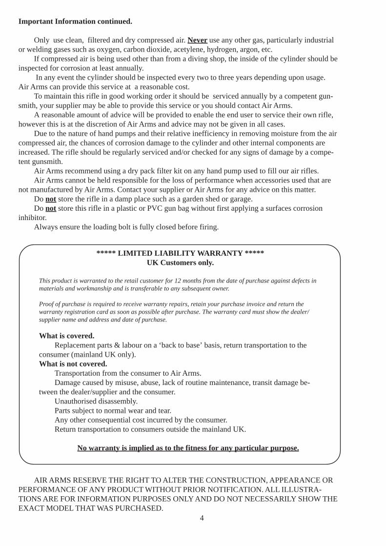
The set of sights supplied comes in 2 pieces, Fig5, the front sight and rear sight, and both fit ontodovetail mountings on the rifle.
Firstly making sure that the thumb screw isloose, slide the rear sight onto the dovetails and intoposition Fig 6. Once the sight is in position, thethumb screw can be tightened, being careful not toover-tighten the screw Fig 7. When the sight is on thedovetail it can be moved forwards and backwards toestablish the proper eye relief for each position.
If not already fitted, fit the riser block to the bottom of the front sight Fig 8. Note: If the riserblock is not fitted on the barrel the rifle cannot be properly sighted in.
The sight can now be fitted into the dovetails on the muzzle Fig 9.The sight tunnel should be fitted with the screw on the left side facing the rear of the gun. When
in place the screw can be tightened Fig 10 , care must be taken as the screw and nut are mountedinto the plastic moulding and over tightening will damage the sight.
.
7
Filling the Cylinder.
Removing the cylinder from the rifle.
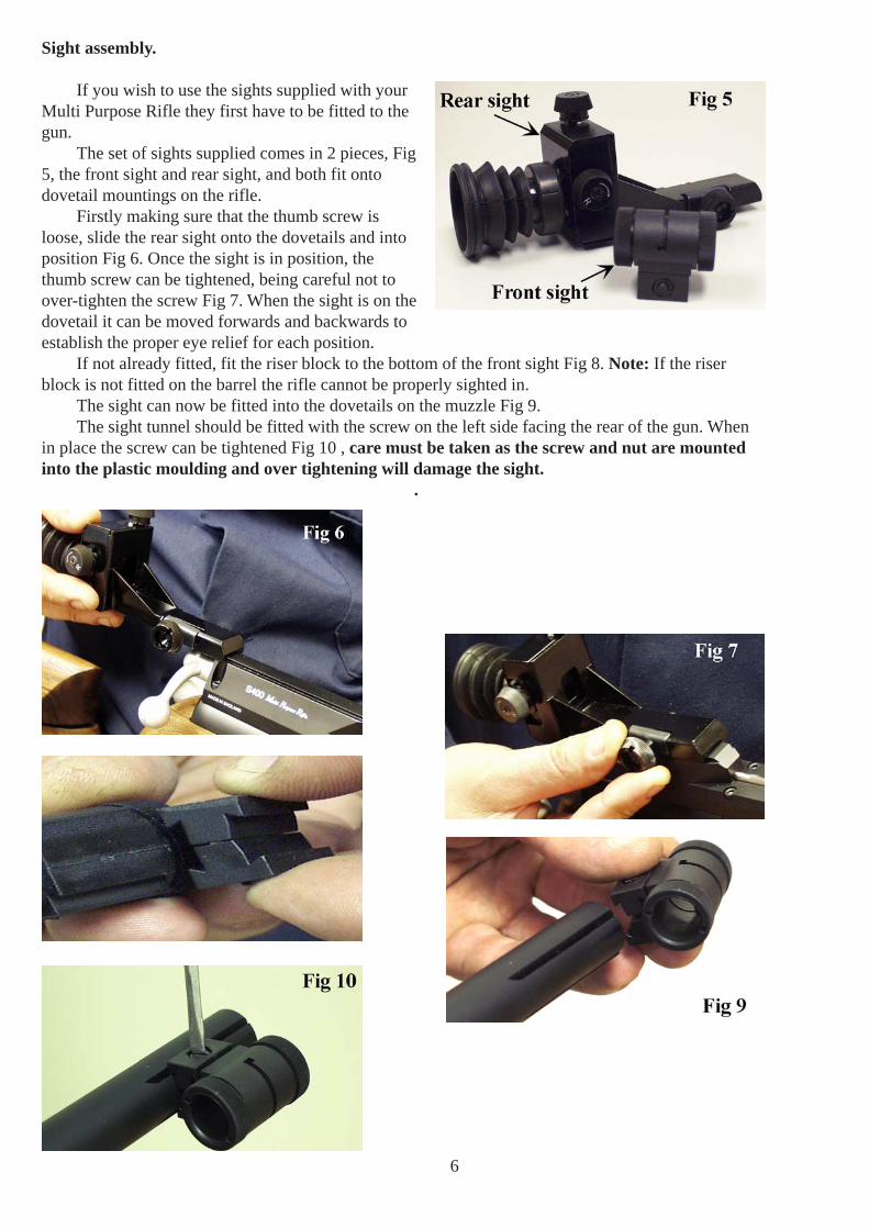
To fill the cylinder it must first be removed from the main body of the rifle. This is achieved byunscrewing the cylinder in a anticlockwise direction. Fig 11. The cylinder should only be hand tight, ifthis is not the case use the spanner provided to loosen the cylinder, then continue without the spannerFig 12.
Note. When removing the cylinder from the rifle there may be a sound of air escaping, this isnormal. Unscrew the cylinder enough to allow the air seal to break,wait for the release of air to stopthen unscrew the cylinder the rest of the way.
Once the cylinder has been completely unscrewed remove it from the rifle.
Filling adaptor.
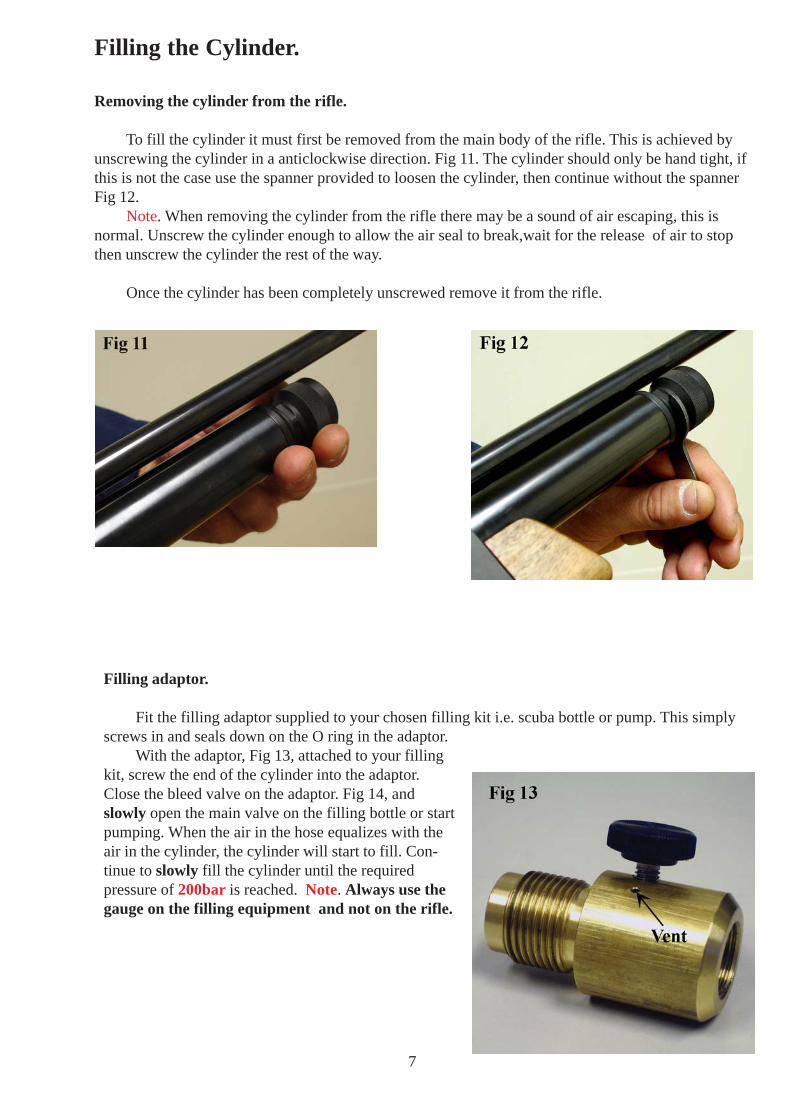
Fit the filling adaptor supplied to your chosen filling kit i.e. scuba bottle or pump. This simplyscrews in and seals down on the O ring in the adaptor.
With the adaptor, Fig 13, attached to your fillingkit, screw the end of the cylinder into the adaptor.Close the bleed valve on the adaptor. Fig 14, andslowly open the main valve on the filling bottle or startpumping. When the air in the hose equalizes with theair in the cylinder, the cylinder will start to fill. Con-tinue to slowly fill the cylinder until the requiredpressure of 200bar is reached. Note. Always use thegauge on the filling equipment and not on the rifle.
8
Once the desired pressure is reached close the mainvalve on the filling bottle or stop pumping. Open thebleed valve on the adaptor, this will vent the trapped airin the hose and allow the cylinder to be unscrewed fromthe adaptor. If you don’t vent the adaptor, air trapped inthe hoses makes removing the cylinder from the fillingkit very difficult and may cause damage to the adaptorseals.
With the vent screw open unscrew the cylinderfrom the filling adaptor.
Cock the action (this is to make sure the firingvalve is closed to stop air venting down the barrel) andscrew the cylinder back onto the rifle. The cylindershould be hand tight.
DO NOT USE THE SPANNER TO TIGHTENTHE CYLINDER ONTO THE RIFLE.
REMEMBER THE RIFLE IS NOW IN A COCKED STATE AND READY TO FIRE, ITSHOULD NOW BE DE-COCKED OR FIRED OFF.
Note. The threads of the cylinder and cylinder extension, (where the cylinder screws into therifle) must be protected and kept free of grit or dust. A thin coating of grease, such as Napier VP90gun grease, may be applied to reduce friction on the threads.
It is also recommend that the cylinder pressure be allowed to fall to 100bar-110bar beforeremoving to fill. Although this is not critical it will make the removal of the cylinder to refill easier.
Note on pumps.
If you are going to use a pump as your filling kityou will also need the pump adaptor, Fig 15, availablefrom Air Arms. Order reference. Z2128-300.
Air Arms recommend that pump usage instructionsare closely followed so as not to damage the cylinder ofthe rifle.
Also available for the HILLS pump is a drypacfilter kit which will remove most of the moisture in theatmoshere.
9
Cocking and Loading the rifle.
To cock the S400 Multi Purpose Rifle hold the gun firmly in one hand and with the other hold thebolt as shown in Fig 16. Lift the bolt up and pull straight backwards until you hear a click, this is thesear engaging the striker (In the pictures below, the sights have been removed for demonstration pur-poses).
If the bolt is held with 2 fingers on one side of the bolt and the thumb on the other side, as in Fig17, the cocking action is smoother and less effort.
10
Once the rifle is cocked, a pellet can be placed into the loading bolt trough Fig 18. The loadingbolt can now be pushed forward to locate the pellet into the barrel. When the bolt is forwards as far asit can go, turn the handle down to lock it into place Fig 19.
WARNING. Extra care must now be taken as the rifle is now cocked, loaded and ready tofire.
De-cocking.
To de-cock the rifle first open the bolt and pull to the rear of the action, as if you were cocking themechanism, now holding the bolt in one hand and pointing the gun to the ground pull the trigger. Youwill feel the load on the bolt increase and you can let go forwards in a controlled fashion.
WARNING. The rifle is now de-cocked but, there is still a pellet in the barrel. It is recom-mended that if you feel you have to de-cock, a better course of action is to fire the rifle into a softarea of ground or other suitable target.
11
Trigger adjustment.
The Multi Purpose Rifle has a two stage trigger. This means that as the trigger is pulled the bot-tom sear gradually disengages with the top sear until the two disengage completely and the rifle fires. Ifthe pressure on the trigger is released before firing, the sears return to their first fully engaged position.This type of trigger allows a very fine but safe operation because it is the release of the second stagethat actually fires the gun. This arrangement is vastly superior to single stage trigger, however it mustbe stated that adjustment of a two stage unit is more difficult than the adjustment of a single stagetrigger.
Trigger positioning.
The trigger on the Multi Purpose Rifle can be adjusted in a variety of ways to make the trigger asefficient as possible. First, the trigger blade can be rotated around the trigger pillar, this allows thefinger to sit perfectly on the trigger.
The blade can be raised or lower on the pillar to make sure that it is in line with the shootersfinger.
The whole trigger blade and pillar assembly can also slide forwards and backwards along thetrigger bar to increase or decrease the length of pull.
These adjustments will allow the gun to be tailored the individual shooter.
Fig 20.
A - Pillar screw.B - Blade screw.C - Second stage adjuster.D - First stage adjuster.E - Weight of pull adjuster.F - Trigger bar.G - Trigger blade.H - Trigger pillar.
Rotating, raising and lowering theblade.
The trigger blade can be rotated andmoved up and down on the trigger pillarby loosening the screw in the blade ‘B’(use the 2mm Allen key supplied.)Fig 21.
Once in position the screw can bere-tightened.
WARNING. Over tighteningscrews or bolts mounted into plasticmay cause damage.
12
Moving the pillar on the trigger bar.
Loosening screw ‘A’ with the1.5mm Allen key (supplied) will allowthe trigger pillar to be moved forwardsand backwards along the trigger bar. (Fig22).
Trigger adjustment.
The operation of the trigger is con-trolled by 3 screws C, D & E (fig 23).
The weight of pull adjustment iscontrolled by screw ‘E’, and is located infront of the trigger, housed in the triggerguard (fig 20).
Clockwise rotation will increase thepull weight and counter-clockwise willdecrease the weight. If the screw is over adjusted in the clockwise direction the spring will becomecoil-bound and may prevent operation of the trigger.
The first stage adjuster ‘D’ is thefirst screw in the trigger bar looking fromthe front of the gun (fig 23). This screwdetermines the length of first stage travelbefore the second stage engages. Clock-wise adjustment reduces the first stagetravel.
The second stage adjuster ‘C’ islocated next to the first stage screw (fig23). This screw determines the exactpull-off point of the trigger.
WARNING. Adjustment of a two-stage trigger can be difficult and should be left to experi-enced and trained technicians. Adjustment to any one of the screws will have a direct effect onthe other two screws and could make the gun unsafe.
If you have no experience of adjusting a two-stage trigger it is highly recommended that youseek guidance or leave the trigger on the factory settings.
Tip.
When adjusting the trigger write down on a piece of paper the number of turns and direction ofeach adjuster screw. This will make it easier to recover the original settings if required.
13
Adjusting the Cheek Piece and Butt Pad.
The cheek piece can be adjusted in two planes first it can be raised and lowered by looseningscrew ‘J’ (fig 25). The cheek piece can also be adjusted a small amount from side to side as in (fig 25),by loosening screws ‘I’.
14
Adjusting butt pad.
The butt pad on the MPR can be adjusting in the vertical plane by loosening screw ‘K’, andsliding the pad into position then re-tightening screw ‘K’. Fig 28.
Spacers can be added in between the butt pad assembly and the butt stock to lengthen the stock.This can be achieved by moving the rubber pad up or down to expose screw ‘L’, Fig 29 at the top andbottom of the butt pad assembly.
Loosening these screw will allow a spacer (available from Air Arms) to be place into the assem-bly.
15
MAINTENANCE
FIXINGSRegularly check the tightness of all fixings. However do not be tempted to over tighten as
some parts are made from aluminium and stripped threads may result. Stripped threads are notcovered by the manufacturers warranty.
BARRELFor ultimate accuracy, clean and re-lube the barrel frequently. It is difficult to advise how often
is best for every circumstance, but every 250 shots is not too often if the desire is to keep the barrelin the best possible condition.
The correct materials are very important. Air arms only uses products made by napier. Listedbelow is the napier product and a more generally available alternative. If possible use napier for thebest results.
As a rule cleaners and oils intended for shotguns and small/fullbore weapons are not suitable.
1> Cut a piece of line three times the length of your barrel, fold in half and tie endstogether. Remove silencer if fitted. Open loading bolt.
2> Feed un-knotted end down barrel from the muzzle end until folded end protrudes about50mm.
3> Cut a 100mm length of ‘rifle clean’ or 100x50mm piece of cloth and pass it between theprotruding loop. Spray the pad with ‘gun cleaner’ or white spirit, turn the rifle upsidedown and pull the line back through the barrel slowly.
4> Repeat steps 2&3 until the pad is clean.5> Repeat steps 2&3 once more without any cleaner on the pad to dry the barrel.6> Repeat steps 2&3 once more with the pad sprayed with ‘gun oil’ or 3 in 1 oil.
IMPORTANT : THE REASON FOR TURNING THE RIFLE UPSIDE DOWN IS TO PREVENT EXCESS CLEANER/OILFROM PASSING DOWN THE TRANSFER PORT INTO THE FIRING VALVE CHAMBER.
LUBRICATION
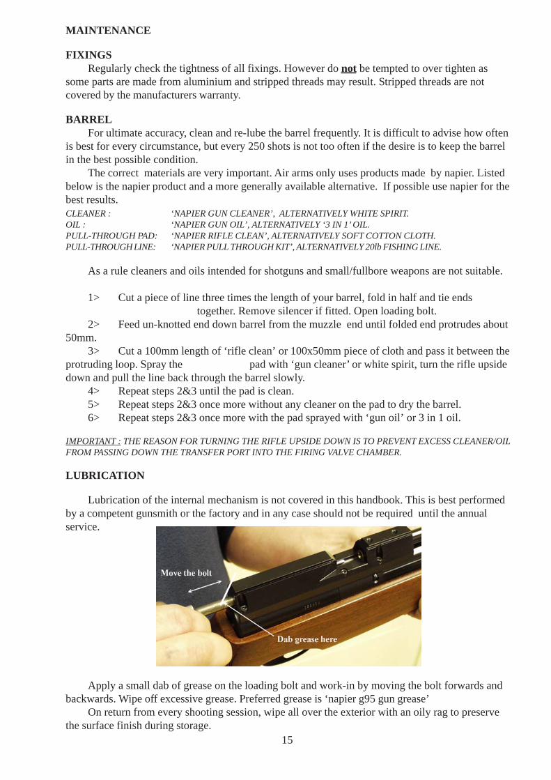
Lubrication of the internal mechanism is not covered in this handbook. This is best performedby a competent gunsmith or the factory and in any case should not be required until the annualservice.
Apply a small dab of grease on the loading bolt and work-in by moving the bolt forwards andbackwards. Wipe off excessive grease. Preferred grease is ‘napier g95 gun grease’
On return from every shooting session, wipe all over the exterior with an oily rag to preservethe surface finish during storage.
PART NO. DESCRIPTION. QTY PART NO. DESCRIPTION. QTYJT450C CHEEK PIECE 1 RN405 BOTTOM PLATE 1
RN400 TOP PLATE 1 RN420 SCREW 1
RN430 SCREW 2 RN425 BUSH 1
RN410FT PILLAR 2 RN435 SCREW 2
KS445 SCREW 3 CZ080 BUTT ASSEMBLY 1
JT455-1 JOINT PIECE 1 JT450B BUTT STOCK 1
RN415 LOCKING PLATE 1
PART LIST <> MPR SPORTER (fore-end)
19
P A R T N O .P A R T S IN
S U B A S S EM B L Y
D ES C R IP T IO N . Q T Y
E4 5 9 A D JU S TA B L E B U TT PA D A S S Y 1
E1 5 0 D IS C S PR IN G 9
E4 1 0 B U TT PA D A D JU S TM EN T R O D 2
E4 5 5 B U TT PA D S L ID ER 1
E4 5 5 - 1 B U TT PA D TO P A R M 1
E4 5 5 - 2 B U TT PA D B O TTM A R M 1
E4 5 7 B U TT PA D S W IV EL PL A TE 1
E4 5 7 - 2 B U TT PA D B A C K IN G PL A TE 1
E4 6 2 B U TT PA D L O C K IN G PL A TE 1
E4 7 1 B U TT PA D S W IV EL PIN 2
E4 7 6 B U TT PA D L O C K IN G A R M S C R EW 4
E4 9 6 B U TT PA D PIL L A R S C R EW 2
R N 4 2 0 S TO C K A D JU S TER S C R EW 3
JT4 0 5 - F IX IN G PL A TE 1
P A R T L IS T < > M P R M E T A L B U T T P A D K IT
20
ITEM NO.
PART NUMBER
DESCRIPTION QTY.ITEM NO.
PART NUMBER
DESCRIPTION QTY.
1 S310 STRIKER BODY 1 16 S430 COVER PLATE 12 S425 2x15.8 Roller 2 17 S324 M3X5 CHEESE HEAD 23 S312 TRIGGER CHASSIS 1 18 JT420 TRIGGER BAR 14 TX398 3x11.8 ROLLER 1 19 TX432 LOCKING PAD 15 S495 TOP SEAR SPRING 1 20 S421 M3x10 Socket Set Ball End 26 S496 M3x6 CAP 1 21 JT330 TRIGGER PILLAR 17 S322 M4x12 CSK 1 22 BB268 M2X4 18 S326 2x11.8 ROLLER 4 23 RN350 TRIGGER SHOE 19 TX236 M4x16 CAP 1 24 RN351 M3 NUT 110 S320-2 TOP SEAR 1 25 RN352 TRIGGER SCREW SHOE 111 S325-2 BOTTOM SEAR 1 26 S315 TRIGGER GUARD 112 S321-2 MIDDLE SEAR 1 27 TX381 M5x6 SOC SET CONE POINT 113 S329 BS004 O RING 3 28 RN170 BISSEL PIN 114 S328 BS005 O RING 1 29 S316 M4X25 CAP 115 S319 SPRING 1 30 TX460 M4X12 SOC CAP 1
TRIGGER UNIT PART LIST
21
ITEM NO.
PART NUMBER
DESCRIPTION QTY.
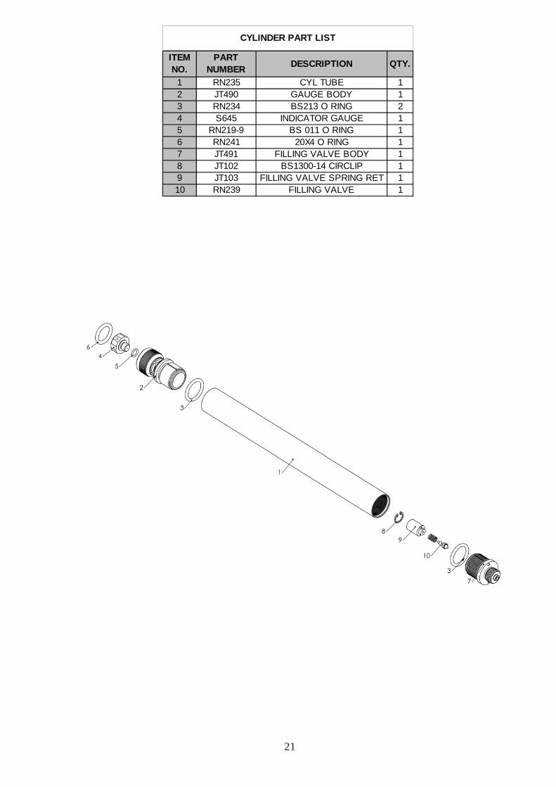
1 RN235 CYL TUBE 12 JT490 GAUGE BODY 13 RN234 BS213 O RING 24 S645 INDICATOR GAUGE 15 RN219-9 BS 011 O RING 16 RN241 20X4 O RING 17 JT491 FILLING VALVE BODY 18 JT102 BS1300-14 CIRCLIP 19 JT103 FILLING VALVE SPRING RET 110 RN239 FILLING VALVE 1
CYLINDER PART LIST
22
Technical Information.
Weights and measures.
Overall weight.
Sporter. 3.15kg.Precision with rubber pad. 3.17kg.
Overall Length.
Sporter. 925mm (36 3/8”).Precision with rubber pad. 1040mm (41”).
Barrel length. 480mm (18 7/8”).Barrel length including muzzle. 522mm (20 1/2”).Barrel length including long muzzle. 545mm (21 1/2”).
Length of sight line.Sporter. 645mm (25 3/8”).Precision. 760mm (29 7/8”)
Length of accessory rails.
Internal (optional on sporter). 192mm (7 1/2”).External. 260mm (10 1/4”).