32
User’s Manual ACS550-PD 3R Irrigation Packaged Drive Supplement to ACS550-U1 User’s Manual
User’s Manual
ACS550-PD 3R Irrigation Packaged Drive Supplement to ACS550-U1 User’s Manual

2 ACS550-PD 3R Irrigation Packaged Drive
ACS550 Drive Manuals GENERAL MANUALS
ACS550-U1 User’s Manual (1…200 HP)• Safety• Installation• Start-Up• EmbeddedFieldbus• FieldbusAdapter• Diagnostics• Maintenance• TechnicalDataACS550 Technical Reference Manual (available in electronic format only)• DetailedProductDescription• PracticalEngineeringGuides
©2015ABBInc.AllRightsReserved.
ACS550-PD 3R Irrigation Packaged Drive 3
Table of Contents
Table of Contents
SafetyUseofWarningsandNotes..............................................4
InstallationApplication.......................................................................5InputDisconnectFeaturesandFunctions........................5InstallationFlowChart......................................................7Lifting...............................................................................8InstallingtheDrive...........................................................11InstallingtheWiring..........................................................16TypicalControlSchematic................................................19
Application GuidesStandardConfiguration....................................................21OptionalConfiguration-SoftPipeFill...............................22
Technical DataRatings.............................................................................23InputPowerConnections.................................................24PowerConnectionTerminals...........................................24DimensionsandWeights.................................................27ApplicableStandards.......................................................29
Maintenance MaintenanceIntervals......................................................31DriveModuleFanReplacement.......................................31
4 ACS550-PD 3R Irrigation Packaged Drive
Safety
Safety
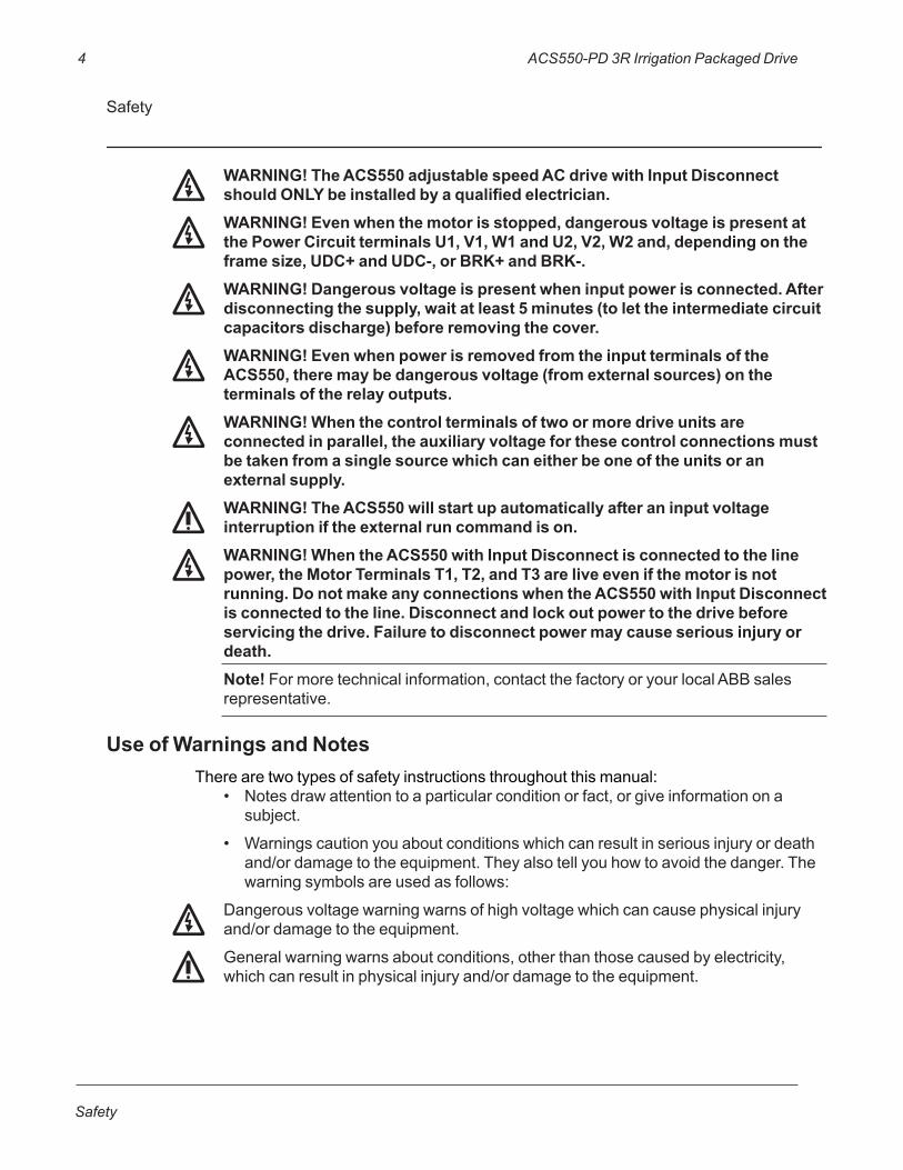
WARNING! The ACS550 adjustable speed AC drive with Input Disconnect should ONLY be installed by a qualified electrician.WARNING! Even when the motor is stopped, dangerous voltage is present at the Power Circuit terminals U1, V1, W1 and U2, V2, W2 and, depending on the frame size, UDC+ and UDC-, or BRK+ and BRK-.WARNING! Dangerous voltage is present when input power is connected. After disconnecting the supply, wait at least 5 minutes (to let the intermediate circuit capacitors discharge) before removing the cover. WARNING! Even when power is removed from the input terminals of the ACS550, there may be dangerous voltage (from external sources) on the terminals of the relay outputs.WARNING! When the control terminals of two or more drive units are connected in parallel, the auxiliary voltage for these control connections must be taken from a single source which can either be one of the units or an external supply.WARNING! The ACS550 will start up automatically after an input voltage interruption if the external run command is on.WARNING! When the ACS550 with Input Disconnect is connected to the line power, the Motor Terminals T1, T2, and T3 are live even if the motor is not running. Do not make any connections when the ACS550 with Input Disconnect is connected to the line. Disconnect and lock out power to the drive before servicing the drive. Failure to disconnect power may cause serious injury or death.Note! Formoretechnicalinformation,contactthefactoryoryourlocalABBsalesrepresentative.
Use of Warnings and NotesTherearetwotypesofsafetyinstructionsthroughoutthismanual:
• Notesdrawattentiontoaparticularconditionorfact,orgiveinformationonasubject.
• Warningscautionyouaboutconditionswhichcanresultinseriousinjuryordeathand/ordamagetotheequipment.Theyalsotellyouhowtoavoidthedanger.Thewarningsymbolsareusedasfollows:
Dangerousvoltagewarningwarnsofhighvoltagewhichcancausephysicalinjuryand/ordamagetotheequipment.
Generalwarningwarnsaboutconditions,otherthanthosecausedbyelectricity,whichcanresultinphysicalinjuryand/ordamagetotheequipment.

ACS550-PD 3R Irrigation Packaged Drive 5
Installation
Installation
Studytheseinstallationinstructionscarefullybeforeproceeding.Failuretoobservethewarningsandinstructionsmaycauseamalfunctionorpersonalhazard.
WARNING! Before you begin read “Safety” on page 1.
WARNING! When the ACS550 with Input Disconnect is connected to the line power, the Motor Terminals T1, T2, and T3 are live even if the motor is not running. Do not make any connections when the ACS550 with Input Disconnect is connected to the line. Disconnect and lock out power to the drive before servicing the drive. Failure to disconnect power may cause serious injury or death.
ApplicationThismanualcontainssupplementalinformationthatisuniquetoACS550inputdisconnectconfigurations(PD).Refertothebasemanual,AC550-U1User’sManual,forallotherinformation.
Input Disconnect Features and FunctionsTheACS550withInputDisconnectisanACS550ACadjustablefrequencydrivepackagedwithaninputdisconnectswitchandwithadoormounted,externaloperatinghandle.TheoperatinghandlecanbepadlockedintheOFFposition(padlocknotsupplied).EnclosureareULType3R(NEMA3R).
Thefollowingisatypicalpowerdiagram.
ACS550
DrivewithInputDisconnect
Motor3PhaseDrive 33
DisconnectSwitchorCircuitBreaker
InputPower
6 ACS550-PD 3R Irrigation Packaged Drive
Installation
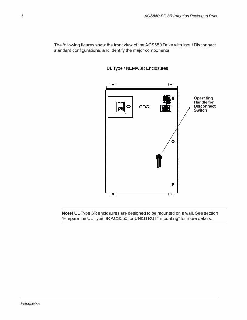
ThefollowingfiguresshowthefrontviewoftheACS550DrivewithInputDisconnectstandardconfigurations,andidentifythemajorcomponents.
Note!ULType3Renclosuresaredesignedtobemountedonawall.Seesection“PreparetheULType3RACS550forUNISTRUT®mounting”formoredetails.
ULType/NEMA3REnclosures
Operating Handle for Disconnect Switch
ACS550-PD 3R Irrigation Packaged Drive 7
Installation
Installation Flow Chart
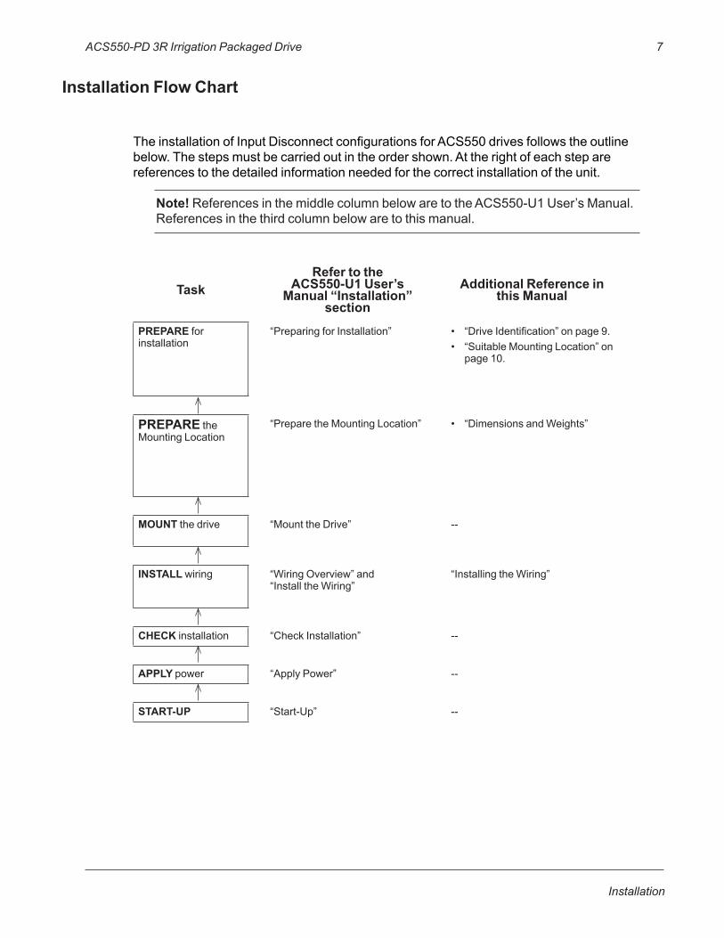
TheinstallationofInputDisconnectconfigurationsforACS550drivesfollowstheoutlinebelow.Thestepsmustbecarriedoutintheordershown.Attherightofeachsteparereferencestothedetailedinformationneededforthecorrectinstallationoftheunit.
Note! ReferencesinthemiddlecolumnbelowaretotheACS550-U1User’sManual.Referencesinthethirdcolumnbelowaretothismanual.
TaskRefer to the
ACS550-U1 User’s Manual “Installation”
section
Additional Reference in this Manual
PREPAREforinstallation
“PreparingforInstallation” • “DriveIdentification”onpage9.• “SuitableMountingLocation”on
page10.
PREPAREtheMountingLocation
“PreparetheMountingLocation” • “DimensionsandWeights”
MOUNT thedrive “MounttheDrive” --
INSTALLwiring “WiringOverview”and“InstalltheWiring”
“InstallingtheWiring”
CHECKinstallation “CheckInstallation” --
APPLY power “ApplyPower” --
START-UP “Start-Up” --
8 ACS550-PD 3R Irrigation Packaged Drive
Installation
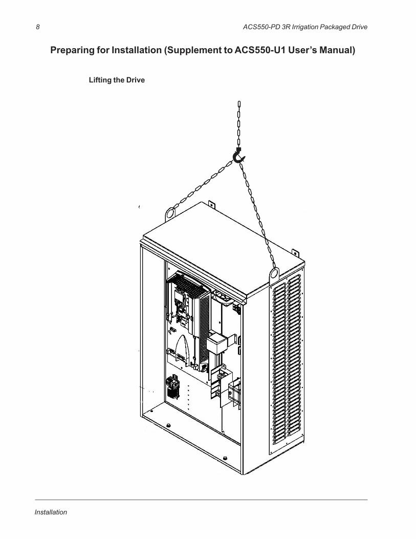
Preparing for Installation (Supplement to ACS550-U1 User’s Manual)
Lifting the Drive
ACS550-PD 3R Irrigation Packaged Drive 9
Installation
Preparing for Installation (Supplement to ACS550-U1 User’s Manual)
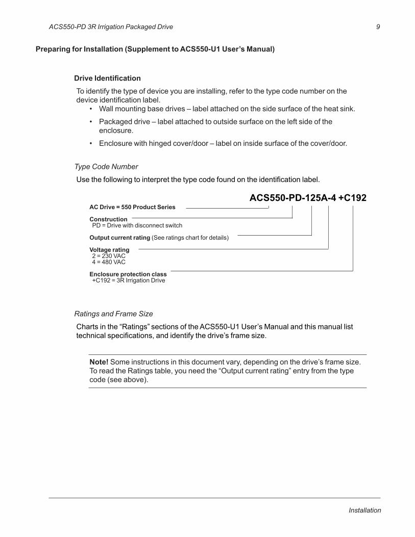
Drive IdentificationToidentifythetypeofdeviceyouareinstalling,refertothetypecodenumberonthedeviceidentificationlabel.
• Wallmountingbasedrives–labelattachedonthesidesurfaceoftheheatsink.
• Packageddrive–labelattachedtooutsidesurfaceontheleftsideoftheenclosure.
• Enclosurewithhingedcover/door–labeloninsidesurfaceofthecover/door.
Type Code Number
Usethefollowingtointerpretthetypecodefoundontheidentificationlabel.
ACS550-PD-125A-4 +C192AC Drive = 550 Product Series
ConstructionPD=DrivewithdisconnectswitchOutput current rating (Seeratingschartfordetails)
Voltage rating2=230VAC4=480VAC
Enclosure protection class+C192=3RIrrigationDrive
Ratings and Frame Size
Chartsinthe“Ratings”sectionsoftheACS550-U1User’sManualandthismanuallisttechnicalspecifications,andidentifythedrive’sframesize.
Note! Someinstructionsinthisdocumentvary,dependingonthedrive’sframesize.ToreadtheRatingstable,youneedthe“Outputcurrentrating”entryfromthetypecode(seeabove).

10 ACS550-PD 3R Irrigation Packaged Drive
Installation
Suitable Mounting LocationForselectingasuitablemountinglocationforconfigurations,referto:
• PreparingforinstallationintheACS550-U1User’sManual,and
• TheTechnicalDatasectionofthismanualforinformationondimensionsandweights.
Installing the Drive (Supplement to ACS550-U1 User’s Manual)
WARNING! Metal shavings or debris in the enclosure can damage electrical equipment and create a hazardous condition. Where parts, such as conduit plates require cutting or drilling, first remove the part. If that is not practical, cover nearby electrical components to protect them from all shavings or debris. Do not connect or disconnect input or output power wiring, or control wires, when power is applied. Never connect line voltage to drive output Terminals T1, T2, and T3. Do not make any voltage tolerance tests (Hi Pot or Megger) on any part of the unit. Disconnect motor wires before taking any measurements in the motor or motor wires. Make sure that power factor correction capacitors are not connected between the drive and the motor.
Prepare the Mounting Location
TheACS550shouldonlybemountedwherealloftherequirementsdefinedin“PreparingforInstallation”aremet.
Mount the Drive
1. Useahoisttomovethecabinetintoposition.
Note! If the cabinet location does not provide access to the cabinet sides, be sure to re-mount side panels before positioning cabinet.
2. Installandtightenmountingbolts.
ACS550-PD 3R Irrigation Packaged Drive 11
Installation
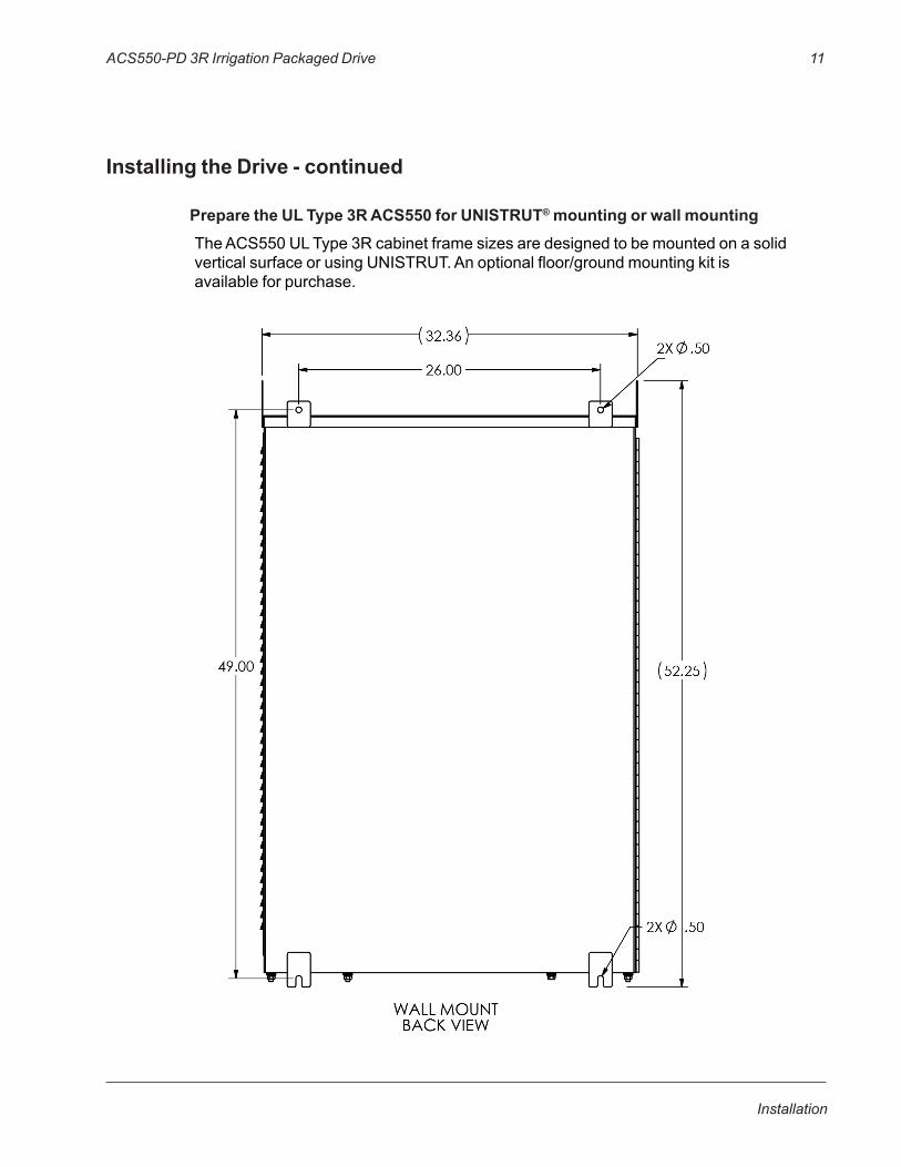
Installing the Drive - continued
Prepare the UL Type 3R ACS550 for UNISTRUT® mounting or wall mountingTheACS550ULType3RcabinetframesizesaredesignedtobemountedonasolidverticalsurfaceorusingUNISTRUT.Anoptionalfloor/groundmountingkitisavailableforpurchase.
12 ACS550-PD 3R Irrigation Packaged Drive
Installation
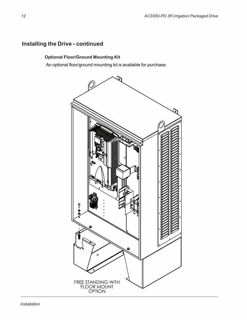
Installing the Drive - continued
Optional Floor/Ground Mounting KitAnoptionalfloor/groundmountingkitisavailableforpurchase.
ACS550-PD 3R Irrigation Packaged Drive 13
Installation
3/8 FLAT WASHERHW1000A38(24) REQ'D.
3/8 LOCK WASHERHW1001A38(24) REQ'D.
3/8-16X1HEX HEADCAP SCREW10XN3816A16(12) REQ'D.
3/8-16HEX NUTV6401538(12) REQ'D.
5.01 5.01 17.74
6.81
13.62
FLOOR PLAN LAYOUT
(6) X 3/8-16 STUDGRADE 5 OR BETTER
REMOUNTED SCREWS
10 X .44
.62 2.00
16.00 17.38
9.00
FRO
M L
EFT
SURF
AC
E O
F EN
CLO
SURE .6
2
7.2
2
24.
78
31.
38
BOTTOM VIEW
3/8-16 FLAT WASHERGRADE 5 OR BETTER
3/8-16 LOCK WASHERGRADE 5 OR BETTER
3/8-16 HEX NUTGRADE 5 OR BETTER
3/8-16 STUDGRADE 5 OR BETTER
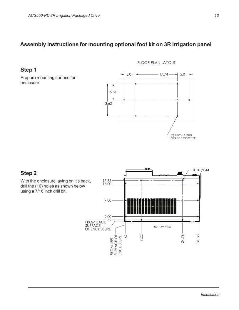
Step 1Preparemountingsurfaceforenclosure.
Step 2Withtheenclosurelayingonit’sback,drillthe(10)holesasshownbelowusinga7/16inchdrillbit.
Assembly instructions for mounting optional foot kit on 3R irrigation panel
14 ACS550-PD 3R Irrigation Packaged Drive
Installation
3/8 FLAT WASHERHW1000A38(24) REQ'D.
3/8 LOCK WASHERHW1001A38(24) REQ'D.
3/8-16X1HEX HEADCAP SCREW10XN3816A16(12) REQ'D.
3/8-16HEX NUTV6401538(12) REQ'D.
5.01 5.01 17.74
6.81
13.62
FLOOR PLAN LAYOUT
(6) X 3/8-16 STUDGRADE 5 OR BETTER
REMOUNTED SCREWS
10 X .44
.62 2.00
16.00 17.38
9.00
FRO
M L
EFT
SURF
AC
E O
F EN
CLO
SURE .6
2
7.2
2
24.
78
31.
38
BOTTOM VIEW
3/8-16 FLAT WASHERGRADE 5 OR BETTER
3/8-16 LOCK WASHERGRADE 5 OR BETTER
3/8-16 HEX NUTGRADE 5 OR BETTER
3/8-16 STUDGRADE 5 OR BETTER
3/8 FLAT WASHERHW1000A38(24) REQ'D.
3/8 LOCK WASHERHW1001A38(24) REQ'D.
3/8-16X1HEX HEADCAP SCREW10XN3816A16(12) REQ'D.
3/8-16HEX NUTV6401538(12) REQ'D.
5.01 5.01 17.74
6.81
13.62
FLOOR PLAN LAYOUT
(6) X 3/8-16 STUDGRADE 5 OR BETTER
REMOUNTED SCREWS
10 X .44
.62 2.00
16.00 17.38
9.00
FRO
M L
EFT
SURF
AC
E O
F EN
CLO
SURE .6
2
7.2
2
24.
78
31.
38
BOTTOM VIEW
3/8-16 FLAT WASHERGRADE 5 OR BETTER
3/8-16 LOCK WASHERGRADE 5 OR BETTER
3/8-16 HEX NUTGRADE 5 OR BETTER
3/8-16 STUDGRADE 5 OR BETTER
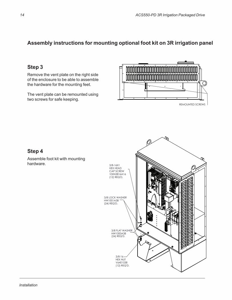
Step 3Removetheventplateontherightsideoftheenclosuretobeabletoassemblethehardwareforthemountingfeet.
Theventplatecanberemountedusingtwoscrewsforsafekeeping.
Step 4Assemblefootkitwithmountinghardware.
Assembly instructions for mounting optional foot kit on 3R irrigation panel
ACS550-PD 3R Irrigation Packaged Drive 15
Installation
3/8 FLAT WASHERHW1000A38(24) REQ'D.
3/8 LOCK WASHERHW1001A38(24) REQ'D.
3/8-16X1HEX HEADCAP SCREW10XN3816A16(12) REQ'D.
3/8-16HEX NUTV6401538(12) REQ'D.
5.01 5.01 17.74
6.81
13.62
FLOOR PLAN LAYOUT
(6) X 3/8-16 STUDGRADE 5 OR BETTER
REMOUNTED SCREWS
10 X .44
.62 2.00
16.00 17.38
9.00
FRO
M L
EFT
SURF
AC
E O
F EN
CLO
SURE .6
2
7.2
2
24.
78
31.
38
BOTTOM VIEW
3/8-16 FLAT WASHERGRADE 5 OR BETTER
3/8-16 LOCK WASHERGRADE 5 OR BETTER
3/8-16 HEX NUTGRADE 5 OR BETTER
3/8-16 STUDGRADE 5 OR BETTER
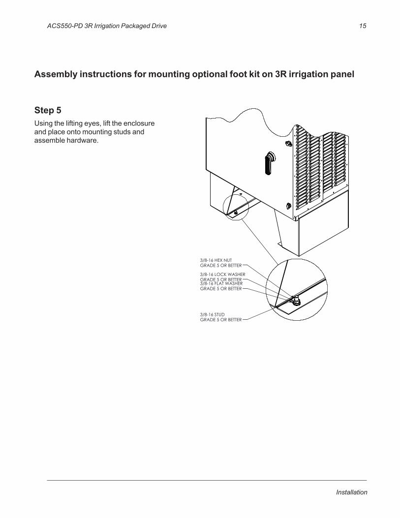
Step 5Usingtheliftingeyes,lifttheenclosureandplaceontomountingstudsandassemblehardware.
Assembly instructions for mounting optional foot kit on 3R irrigation panel

16 ACS550-PD 3R Irrigation Packaged Drive
Installation
Installing the Wiring (Supplement to ACS550-U1 User’s Manual)
Wiring Requirements
Refertothe“WiringRequirements”SectionintheACS550-U1User’sManual.TherequirementsapplytoallACS550drives.Inparticular:
• Useseparate,metalconduitrunsforthefollowingdifferentclassesofwiring:
– Inputpowerwiring.– Motorwiring.– Control/communicationswiring.
• Properlyandindividuallygroundthedrive,themotorandcableshields.
Wiring OverviewPower Connection – Standard Drive with Input Disconnect (Wall Mounted)
ThefollowingfiguresshowtheStandardDrivewithInputDisconnect(wallmounted)typicallayout.(RefertotheACS550-U1User’sManualand3RIrrigationControlSchematicforcontrolconnectionstothedrive.)
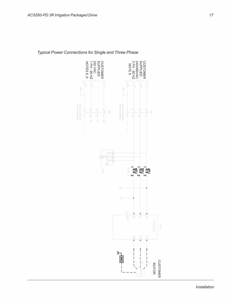
Install the Line Input Wiring Line Input Connections – Standard Drive with Input Disconnect Configurations
Connectinputpowertotheterminalsofthedisconnectswitch.Connecttheequipmentgroundingconductortothegroundlug.ThefigurebelowshowstypicalconnectionpointsforStandardACS550DrivewithInputDisconnectconfigurations.
WARNING! Check the motor and motor wiring insulation before connecting the ACS550 to line power. Follow the procedure in the ACS550-U1 User’s Manual. Before proceeding with the insulation resistance measurements, check that the ACS550 is disconnected from incoming line power. Failure to disconnect line power could result in death or serious injury.
Note!Fortheremainderoftheinstallationandstart-up(motorandcontrolwiring)refertotheACS550-U1User’sManual.
ACS550-PD 3R Irrigation Packaged Drive 17
Installation
Typical Power Connections for Single and Three Phase
18 ACS550-PD 3R Irrigation Packaged Drive
Installation
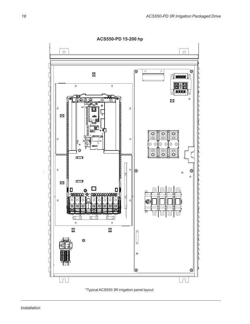
ACS550-PD 15-200 hp
*TypicalACS5503Rirrigationpanellayout
ACS550-PD 3R Irrigation Packaged Drive 19
Installation
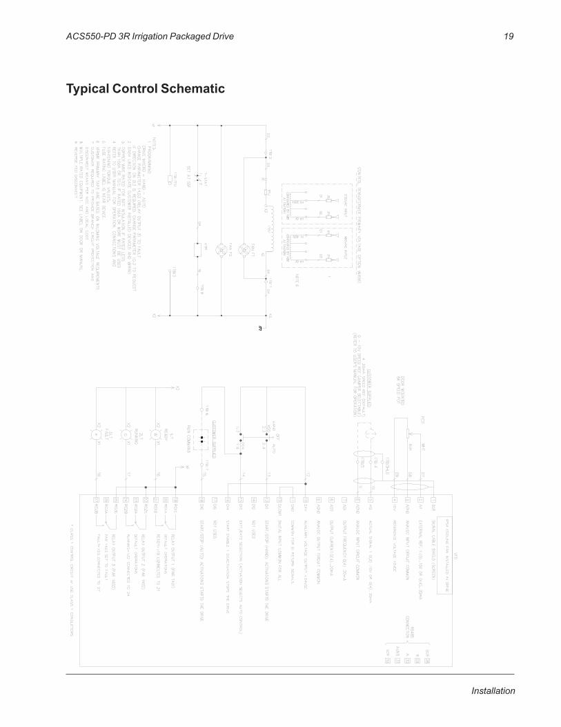
Typical Control Schematic

20 ACS550-PD 3R Irrigation Packaged Drive
Installation
[Thispageintentionallyleftblank]
ACS550-PD 3R Irrigation Packaged Drive 21
Application Guides
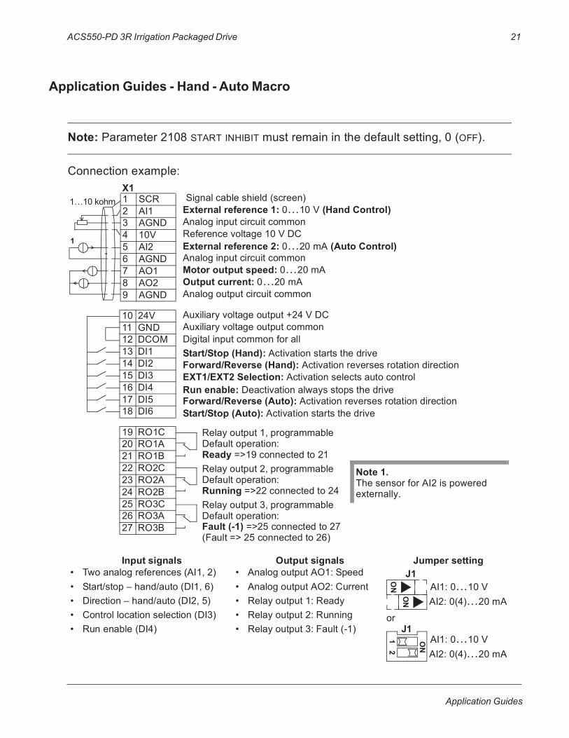
Application Guides - Hand - Auto Macro
Note: Parameter 2108 START INHIBIT must remain in the default setting, 0 (OFF).
Connection example:
Input signals Output signals Jumper setting• Two analog references (AI1, 2)• Start/stop – hand/auto (DI1, 6)• Direction – hand/auto (DI2, 5)• Control location selection (DI3)• Run enable (DI4)
• Analog output AO1: Speed• Analog output AO2: Current• Relay output 1: Ready• Relay output 2: Running• Relay output 3: Fault (-1)
or
1 SCR2 AI13 AGND4 10V5 AI26 AGND7 AO18 AO29 AGND
10 24V11 GND12 DCOM13 DI114 DI215 DI316 DI417 DI518 DI6
19 RO1C20 RO1A21 RO1B22 RO2C23 RO2A24 RO2B25 RO3C26 RO3A27 RO3B
Start/Stop (Hand): Activation starts the driveForward/Reverse (Hand): Activation reverses rotation directionEXT1/EXT2 Selection: Activation selects auto control
Forward/Reverse (Auto): Activation reverses rotation direction Start/Stop (Auto): Activation starts the drive
Run enable: Deactivation always stops the drive
External reference 1: 0…10 V (Hand Control)
Reference voltage 10 V DC
Motor output speed: 0…20 mAOutput current: 0…20 mA
Analog input circuit common
Analog output circuit common
Auxiliary voltage output +24 V DCAuxiliary voltage output commonDigital input common for all
Signal cable shield (screen)
Analog input circuit common External reference 2: 0…20 mA (Auto Control)
Relay output 1, programmableDefault operation:
Relay output 2, programmableDefault operation:
Relay output 3, programmableDefault operation:
Ready =>19 connected to 21
Running =>22 connected to 24
Fault (-1) =>25 connected to 27(Fault => 25 connected to 26)
1
Note 1. The sensor for AI2 is powered externally.
X11…10 kohm
J1AI1: 0…10 VAI2: 0(4)…20 mA
ON
ON
AI1: 0…10 VAI2: 0(4)…20 mA
ON
12
J1

22 ACS550-PD 3R Irrigation Packaged Drive
Application Guides
Application Guides - Optional Configuration for Soft Pipe Fill
recudsnarT eruserP+--
sp 001-0 = Am 02-4
tcatnoC S/S otuA1
1
s
ACS550-PD Packaged Drive with Disconnect 23
Technical Data
TechnicalData
Ratings (Supplement to ACS550-U1 User’s Manual)
Note! The ratings listed below are exceptions to the ratings listed in the ACS550-U1 User’s Manual.
24 ACS550-PD Packaged Drive with Disconnect
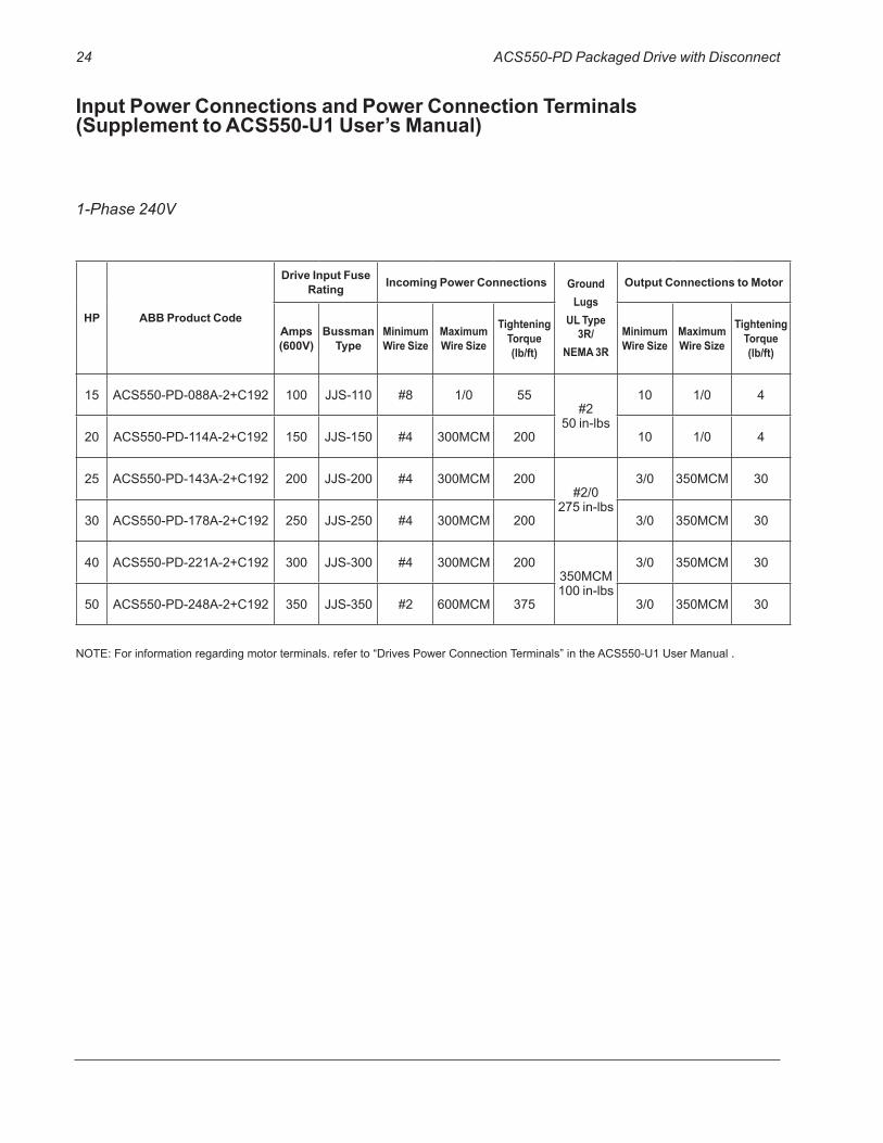
Input Power Connections and Power Connection Terminals (Supplement to ACS550-U1 User’s Manual)
1-Phase 240V
HP ABB Product Code
Drive Input Fuse Rating Incoming Power Connections Ground
LugsUL Type
3R/NEMA 3R
Output Connections to Motor
Amps (600V)
Bussman Type
Minimum Wire Size
Maximum Wire Size
Tightening Torque (lb/ft)
Minimum Wire Size
Maximum Wire Size
Tightening Torque (lb/ft)
15 ACS550-PD-088A-2+C192 100 JJS-110 #8 1/0 55#2
50in-lbs
10 1/0 4
20 ACS550-PD-114A-2+C192 150 JJS-150 #4 300MCM 200 10 1/0 4
25 ACS550-PD-143A-2+C192 200 JJS-200 #4 300MCM 200#2/0
275in-lbs
3/0 350MCM 30
30 ACS550-PD-178A-2+C192 250 JJS-250 #4 300MCM 200 3/0 350MCM 30
40 ACS550-PD-221A-2+C192 300 JJS-300 #4 300MCM 200350MCM100in-lbs
3/0 350MCM 30
50 ACS550-PD-248A-2+C192 350 JJS-350 #2 600MCM 375 3/0 350MCM 30
NOTE:Forinformationregardingmotorterminals.referto“DrivesPowerConnectionTerminals”intheACS550-U1UserManual.

ACS550-PD Packaged Drive with Disconnect 25
Technical Data
Input Power Connections and Power Connection Terminals (Supplement to ACS550-U1 User’s Manual)
3-Phase 240V
HP ABB Product Code
Drive Input Fuse Rating Incoming Power Connections
GroundLugs
UL Type 3R/
NEMA 3R
Output Connections to Motor
Amps (600V)
Bussman Type
Minimum Wire Size
Maximum Wire Size
Tightening Torque (lb/ft)
Minimum Wire Size
Maximum Wire Size
Tightening Torque (lb/ft)
25 ACS550-PD-075A-2+C192 100 JJS-100 #8 1/0 55
#250in-lbs
10 1/0 4
30 ACS550-PD-088A-2+C192 110 JJS-110 #8 1/0 55 10 1/0 4
40 ACS550-PD-114A-2+C192 150 JJS-150 #4 300MCM 200 10 1/0 4
50 ACS550-PD-143A-2+C192 200 JJS-200 #4 300MCM 200#2/0
275in-lbs
3/0 350MCM 30
60 ACS550-PD-178A-2+C192 250 JJS-250 #4 300MCM 200 3/0 350MCM 30
75 ACS550-PD-221A-2+C192 300 JJS-300 #4 300MCM 200350MCM100in-lbs
3/0 350MCM 30
100 ACS550-PD-248A-2+C192 350 JJS-350 #2 600MCM 375 3/0 350MCM 30
NOTE:Forinformationregardingmotorterminals.referto“DrivesPowerConnectionTerminals”intheACS550-U1UserManual.

26 ACS550-PD Packaged Drive with Disconnect
Technical Data
*Shippingcrateaddsapproximately170lbs.
Input Power Connections and Power Connection Terminals (Supplement to ACS550-U1 User’s Manual)
3-Phase 480V
HP ABB Product Code
Drive Input Fuse Rating Incoming Power Connections
GroundLugs
UL Type 3R/
NEMA 3R
Output Connections to Motor
Amps (600V)
Bussman Type
Minimum Wire Size
Maximum Wire Size
Tightening Torque (lb/ft)
Minimum Wire Size
Maximum Wire Size
Tightening Torque (lb/ft)
40 ACS550-PD-059A-4+C192 80 JJS-80 #8 1/0 55
#250in-lbs
10 1/0 4
50 ACS550-PD-072A-4+C192 90 JJS-90 #8 1/0 55 10 1/0 4
60 ACS550-PD-078A-4+C192 100 JJS-100 #8 1/0 55 10 1/0 4
75 ACS550-PD-097A-4+C192 125 JJS-125 #4 300MCM 200 10 1/0 4
100 ACS550-PD-125A-4+C192 175 JJS-175 #4 300MCM 200 3/0 350MCM 30
125 ACS550-PD-157A-4+C192 200 JJS-200 #4 300MCM 200#2/0
375in-lbs
3/0 350MCM 30
150 ACS550-PD-180A-4+C192 250 JJS-250 #2 600MCM 375 3/0 350MCM 30
200 ACS550-PD-246A-4+C192 350 JJS-350 #2 600MCM 375 350MCM100in-lbs 3/0 350MCM 30
NOTE:Forinformationregardingmotorterminals.referto“DrivesPowerConnectionTerminals”intheACS550-U1UserManual.
ACS550-PD Packaged Drive with Disconnect 27
Technical Data
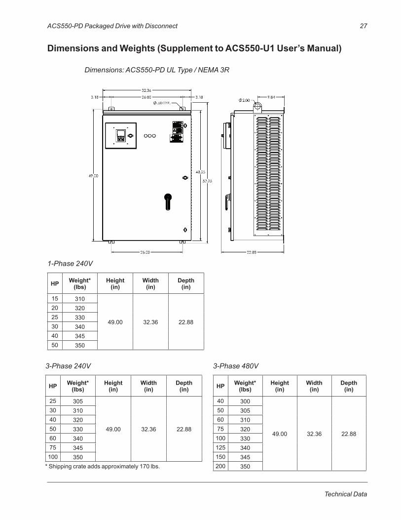
Dimensions and Weights (Supplement to ACS550-U1 User’s Manual)
Dimensions: ACS550-PD UL Type / NEMA 3R
HP Weight* (lbs)
Height (in)
Width (in)
Depth (in)
15 310
49.00 32.36 22.88
20 32025 33030 34040 34550 350
HP Weight* (lbs)
Height (in)
Width (in)
Depth (in)
25 305
49.00 32.36 22.88
30 31040 32050 33060 34075 345100 350
HP Weight* (lbs)
Height (in)
Width (in)
Depth (in)
40 300
49.00 32.36 22.88
50 30560 31075 320100 330125 340150 345200 350
1-Phase 240V
3-Phase 240V 3-Phase 480V
*Shippingcrateaddsapproximately170lbs.
28 ACS550-PD Packaged Drive with Disconnect
Technical Data
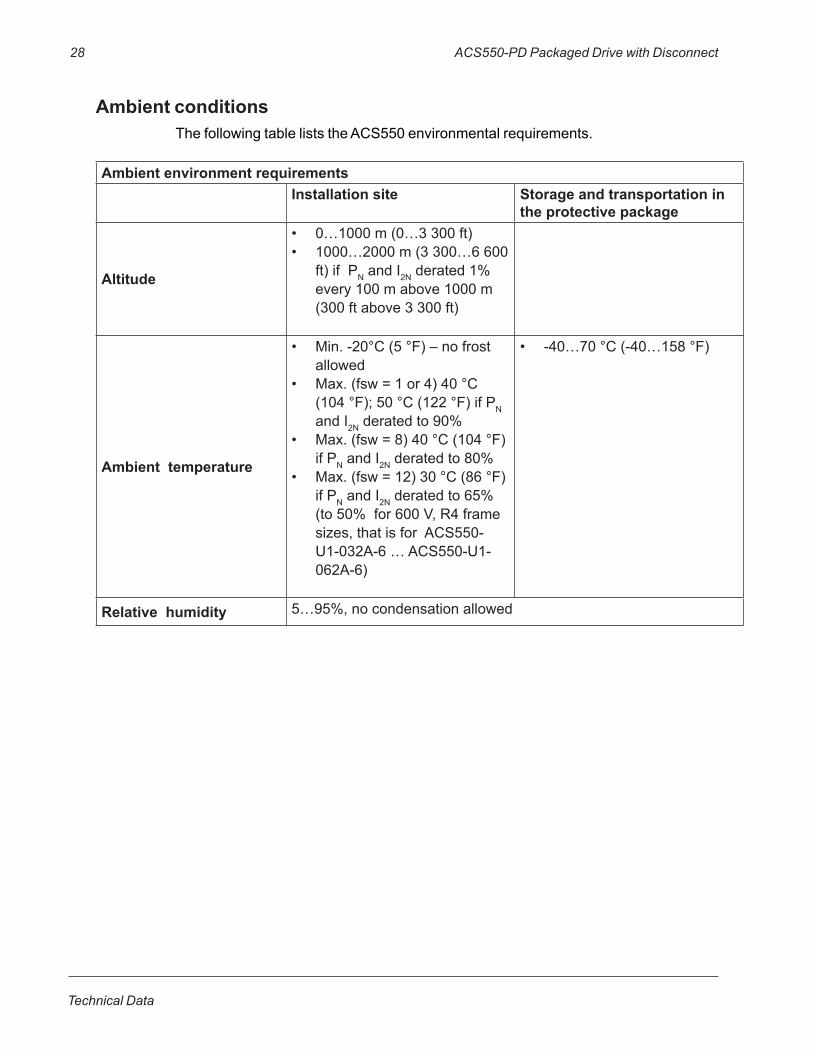
Ambient environment requirementsInstallation site Storage and transportation in
the protective package
Altitude
• 0…1000m(0…3300ft)• 1000…2000m(3300…6600
ft)ifPNandI2Nderated1%every100mabove1000m(300ftabove3300ft)
Ambient temperature
• Min.-20°C(5°F)–nofrostallowed
• Max.(fsw=1or4)40°C(104°F);50°C(122°F)ifPNandI2Nderatedto90%
• Max.(fsw=8)40°C(104°F)ifPNandI2Nderatedto80%
• Max.(fsw=12)30°C(86°F)ifPNandI2Nderatedto65%(to50%for600V,R4framesizes,thatisforACS550-U1-032A-6…ACS550-U1-062A-6)
• -40…70°C(-40…158°F)
Relative humidity 5…95%,nocondensationallowed
Ambient conditionsThefollowingtableliststheACS550environmentalrequirements.

ACS550-PD Packaged Drive with Disconnect 29
Technical Data
Applicable StandardsDrivecompliancewiththefollowingstandardsisidentifiedbythestandards“marks”onthetypecodelabel.
Mark Applicable StandardsUL508CandC22.2No.14
ULStandardforSafety,PowerConversionEquipment,secondeditionandCSAStandardforIndustrialControlEquipment
UL508A ULStandardforSafety,IndustrialControlPanels
C22.2No.14 CSAStandardforIndustrialControlEquipment
Complianceisvalidwiththefollowingprovisions:• Themotorandcontrolcablesarechosenasspecifiedinthismanual.
• Theinstallationrulesofthismanualarefollowed.

30 ACS550-PD Packaged Drive with Disconnect
Technical Data
[Thispageintentionallyleftblank]
ACS550-PD 3R Irrigation Packaged Drive 31
Maintenance
Maintenance
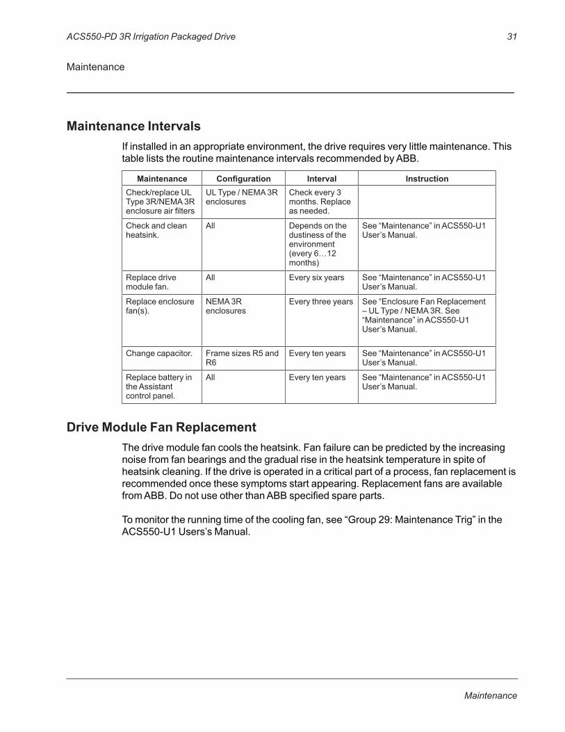
Maintenance IntervalsIfinstalledinanappropriateenvironment,thedriverequiresverylittlemaintenance.ThistableliststheroutinemaintenanceintervalsrecommendedbyABB.
Maintenance Configuration Interval InstructionCheck/replaceULType3R/NEMA3Renclosureairfilters
ULType/NEMA3Renclosures
Checkevery3months.Replaceasneeded.
Checkandcleanheatsink.
All Dependsonthedustinessoftheenvironment(every6…12months)
See“Maintenance”inACS550-U1User’sManual.
Replacedrivemodulefan.
All Everysixyears See“Maintenance”inACS550-U1User’sManual.
Replaceenclosurefan(s).
NEMA3Renclosures
Everythreeyears See“EnclosureFanReplacement–ULType/NEMA3R.See“Maintenance”inACS550-U1User’sManual.
Changecapacitor. FramesizesR5andR6
Everytenyears See“Maintenance”inACS550-U1User’sManual.
ReplacebatteryintheAssistantcontrolpanel.
All Everytenyears See“Maintenance”inACS550-U1User’sManual.
Drive Module Fan ReplacementThedrivemodulefancoolstheheatsink.Fanfailurecanbepredictedbytheincreasingnoisefromfanbearingsandthegradualriseintheheatsinktemperatureinspiteofheatsinkcleaning.Ifthedriveisoperatedinacriticalpartofaprocess,fanreplacementisrecommendedoncethesesymptomsstartappearing.ReplacementfansareavailablefromABB.DonotuseotherthanABBspecifiedspareparts.Tomonitortherunningtimeofthecoolingfan,see“Group29:MaintenanceTrig”intheACS550-U1Users’sManual.

ABB Inc. Discrete Automation & MotionDrives and Controls16250 W. Glendale DriveNew Berlin, WI 53151
Telephone +1 262 752-0696 +1 800 HELP-365
Internet www.abb.com/drives
3AUA0000162200REVBEffective02/01/2015Subjecttochangewithoutnotice.Allrightsreserved.


