32
1601 Temperature Controller Issue date r USER'S MANUAL March 2000 0037 - 75236 1601-0-0C.p65 5/2/00, 1:45 PM 1

1601Temperature Controller
Issue date � USER'S MANUALMarch 2000 0037 - 75236
1601-0-0C.p65 5/2/00, 1:45 PM1

CONTENTS
OUTLINE AND CUT OUT DIMENSIONS .......... IIIMOUNTING REQUIREMENTS .......................... 1CONNECTION DIAGRAMS ................................ 2GENERAL OPERATION ..................................... 5CONFIGURATION HARDWARE SETTINGS ..... 5CONFIGURATION PARAMETERS .................... 6OPERATOR MODE .......................................... 10
Indicators ................................................... 10Pushbutton function ................................... 11Manual reset of the alarms ......................... 11SMART algorithm ...................................... 11Output power OFF ..................................... 12Direct access to the set point ..................... 12Display of the set point value ..................... 12Bargraph operating .................................... 13Lamp test ................................................... 13
OPERATOR PARAMETERS ............................ 13ERROR MESSAGES ........................................ 15GENERAL INFORMATIONS ............................ 17MAINTENANCE ................................................ 18DEFAULT PARAMETERS ............................... A.1
II
1601-0-0C.p65 5/2/00, 1:45 PM2

IV
Model identification
Model
1601 1/16 DIN Temperature Controller, Single Display
Code Output 1 - Heat or Cool
1 Relay, 3 Amps at 250 Vac (Resistive)
6 SSR Drive, 14 Vdc at 20 mA
Code Output 2 - Alarm
1 Relay, 1 Amp at 250 Vac (Resistive load)
Code
0 Add to complete model number
Code Instrument Power
3 100 - 240 Vac
5 24 Vac/dc
Code
0 Add to complete model number
1601 6 1 0 3 0 Typical Model Number
1601-0-0C.p65 5/2/00, 1:45 PM3

OUTLINE AND CUT OUT DIMENSIONS
V
1601-0-0C.p65 5/2/00, 1:45 PM4

VI
1601-0-0C.p65 5/2/00, 1:45 PM5

1
MOUNTING REQUIREMENTS
Select a mounting location where there isminimum vibration and the ambient temperaturerange between 0 and 50 °C (32 and 122 °F).The instrument can be mounted on a panel up to15 mm thick with a square cutout of 45 x 45 mm.For outline and cutout dimensions refer to page IV.The surface texture of the panel must be betterthan 6.3 �m.The instrument is shipped with rubber panelgasket.To assure the IP65 and NEMA 4 protection, insertthe panel gasket between the instrument and thepanel as show in fig. 1.While holding the instrument against the panelproceed as follows:1) insert the gasket in the instrument case;2) insert the instrument in the panel cutout;3) pushing the instrument against the panel, insert
the mounting bracket;4) with a screwdriver, turn the screws with a
torque between 2.7 to 3.5 in-lb (0.3 and 0.4Nm).
Fig. 1
Panelbracket
Screw
Gasket
1601-1-0C.p65 5/2/00, 1:45 PM1
2
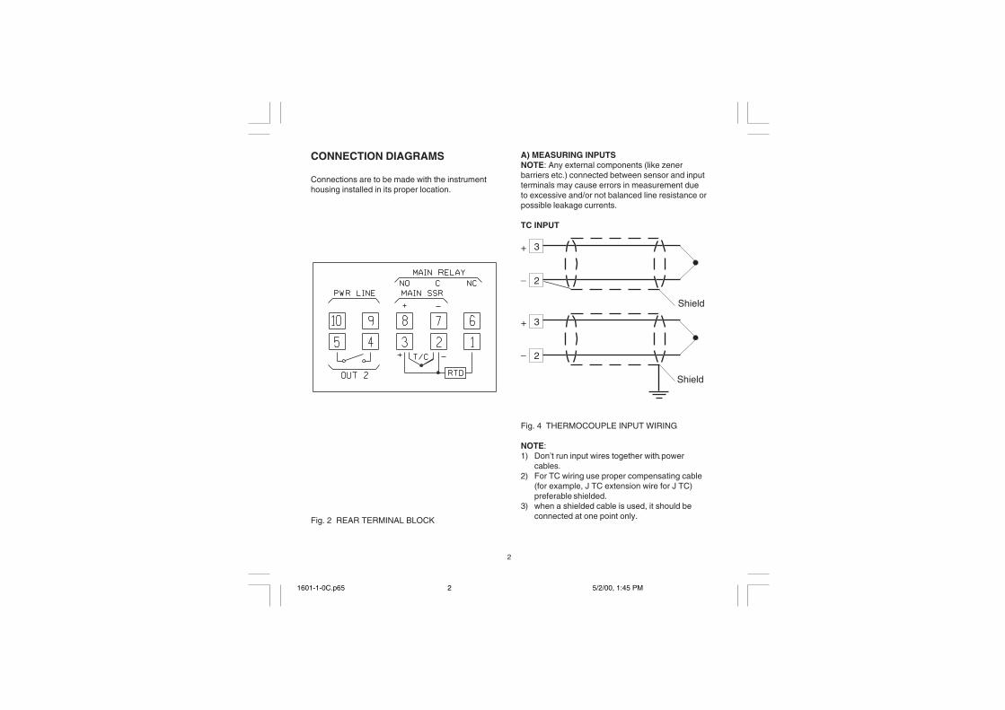
A) MEASURING INPUTSNOTE: Any external components (like zenerbarriers etc.) connected between sensor and inputterminals may cause errors in measurement dueto excessive and/or not balanced line resistance orpossible leakage currents.
TC INPUT
Fig. 4 THERMOCOUPLE INPUT WIRING
NOTE:1) Don’t run input wires together with power
cables.2) For TC wiring use proper compensating cable
(for example, J TC extension wire for J TC)preferable shielded.
3) when a shielded cable is used, it should beconnected at one point only.
Shield
Shield
3
2
+
_
3
2
+
_
CONNECTION DIAGRAMS
Connections are to be made with the instrumenthousing installed in its proper location.
Fig. 2 REAR TERMINAL BLOCK
1601-1-0C.p65 5/2/00, 1:45 PM2
3
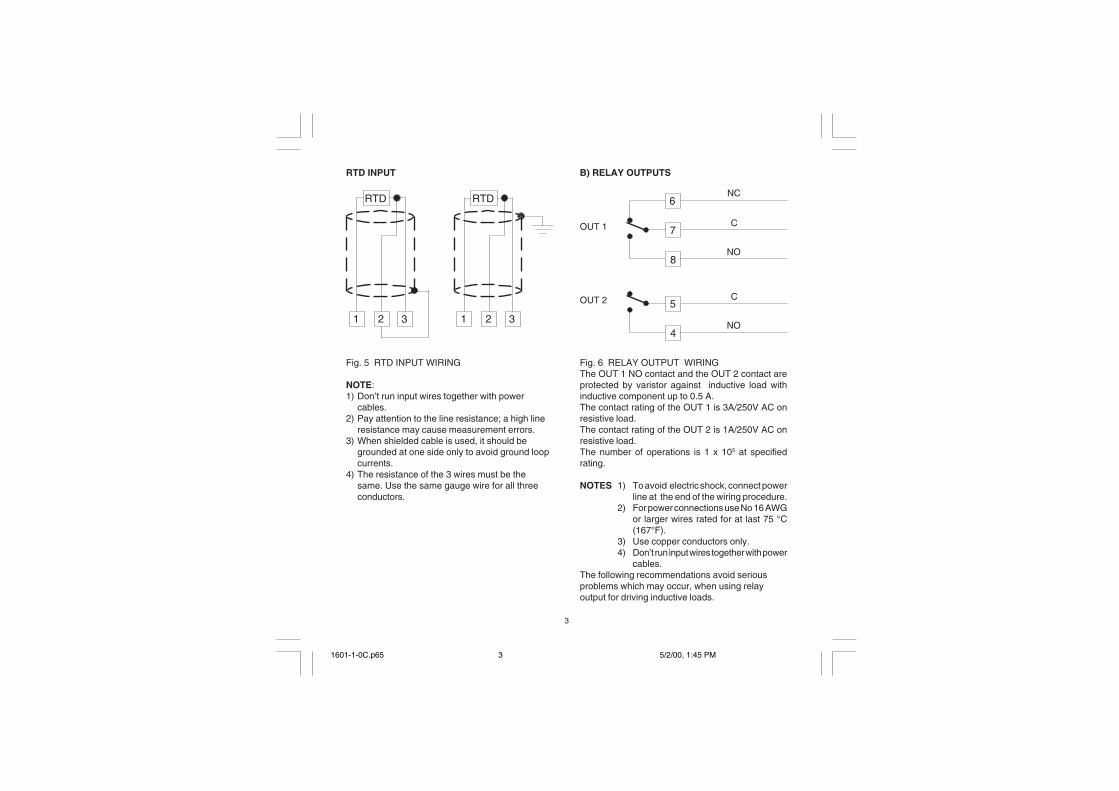
RTD INPUT
Fig. 5 RTD INPUT WIRING
NOTE:1) Don’t run input wires together with power
cables.2) Pay attention to the line resistance; a high line
resistance may cause measurement errors.3) When shielded cable is used, it should be
grounded at one side only to avoid ground loopcurrents.
4) The resistance of the 3 wires must be thesame. Use the same gauge wire for all threeconductors.
1
RTD
32 1
RTD
32
B) RELAY OUTPUTS
Fig. 6 RELAY OUTPUT WIRINGThe OUT 1 NO contact and the OUT 2 contact areprotected by varistor against inductive load withinductive component up to 0.5 A.The contact rating of the OUT 1 is 3A/250V AC onresistive load.The contact rating of the OUT 2 is 1A/250V AC onresistive load.The number of operations is 1 x 10⁵ at specifiedrating.
NOTES 1) To avoid electric shock, connect powerline at the end of the wiring procedure.
2) For power connections use No 16 AWGor larger wires rated for at last 75 °C(167°F).
3) Use copper conductors only.4) Don’t run input wires together with power
cables.The following recommendations avoid seriousproblems which may occur, when using relayoutput for driving inductive loads.
8
6
7C
NC
NO
OUT 1
4
5C
NO
OUT 2
1601-1-0C.p65 5/2/00, 1:45 PM3

4
VOLTAGE OUTPUTS FOR SSR DRIVE
Fig. 8 SSR DRIVE OUTPUT WIRINGIt is a time proportioning output.Logic level 0: Vout < 0.5 V DC.Logic level 1:- 14 V + 20 % @ 20 mA- 24 V + 20 % @ 1 mA.
Maximum current = 20 mA.NOTE: This output is not isolated.A double or reinforced Isolation between instrumentoutput and power supply must be provided by theexternal solid state relay.
SOLID STATERELAY
INDUCTIVE LOADSHigh voltage transients may occur when switchinginductive loads.Through the internal contacts these transients mayintroduce disturbances which can affect theperformance of the instrument.The internal protection (varistor) assures a correctprotection up to 0.5 A of inductive component butthe OUT 1 NC contact is not protected.The same problem may occur when a switch isused in series with the internal contacts as shownin Fig. 7.
Fig. 7 EXTERNAL SWITCH IN SERIES WITHTHE INTERNAL CONTACT
In this cases it is recommended to install anadditional RC network across the external contactas show in Fig. 7 (Chromalox snubber PN 0149-01305 is recommended).The value of capacitor (C) and resistor (R) areshown in the following table.
Anyway the cable involved in relay output wiringmust be as far away as possible from input orcommunication cables.
LOAD(mA)
<40 mA<150 mA<0.5 A
C(�F)
0.0470.1
0.33
R(�)
1002247
P.(W)
1/222
OPERATINGVOLTAGE
260 V AC260 V AC260 V AC
+
_ _+
8
7
OUT 1
LOAD
CR
POWERLINE
1601-1-0C.p65 5/2/00, 1:45 PM4
5
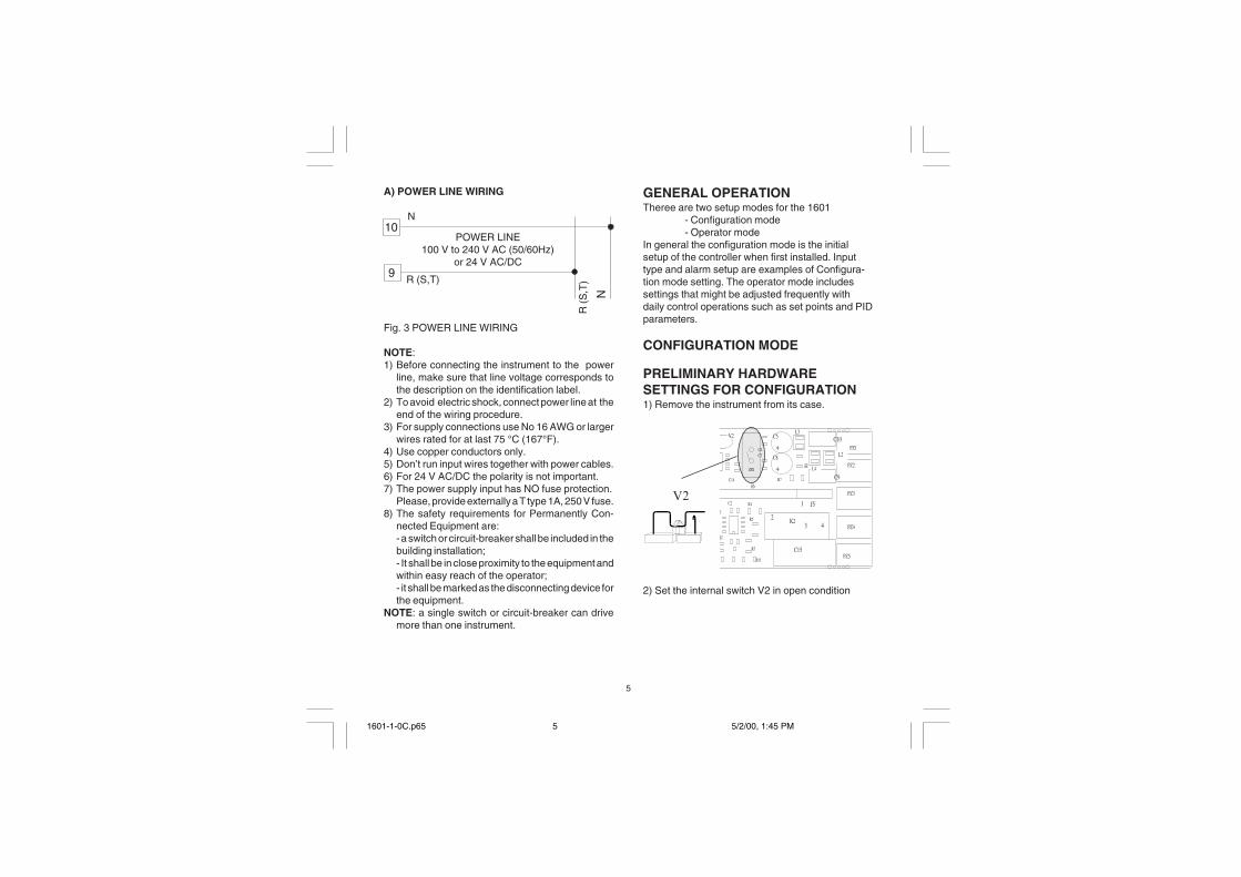
GENERAL OPERATIONTheree are two setup modes for the 1601
- Configuration mode- Operator mode
In general the configuration mode is the initialsetup of the controller when first installed. Inputtype and alarm setup are examples of Configura-tion mode setting. The operator mode includessettings that might be adjusted frequently withdaily control operations such as set points and PIDparameters.
CONFIGURATION MODE
PRELIMINARY HARDWARESETTINGS FOR CONFIGURATION1) Remove the instrument from its case.
2) Set the internal switch V2 in open condition
9
R (
S,T
)R (S,T)
N
10N
POWER LINE100 V to 240 V AC (50/60Hz)
or 24 V AC/DC
A) POWER LINE WIRING
Fig. 3 POWER LINE WIRING
NOTE:1) Before connecting the instrument to the power
line, make sure that line voltage corresponds tothe description on the identification label.
2) To avoid electric shock, connect power line at theend of the wiring procedure.
3) For supply connections use No 16 AWG or largerwires rated for at last 75 °C (167°F).
4) Use copper conductors only.5) Don’t run input wires together with power cables.6) For 24 V AC/DC the polarity is not important.7) The power supply input has NO fuse protection.
Please, provide externally a T type 1A, 250 V fuse.8) The safety requirements for Permanently Con-
nected Equipment are:- a switch or circuit-breaker shall be included in thebuilding installation;- It shall be in close proximity to the equipment andwithin easy reach of the operator;- it shall be marked as the disconnecting device forthe equipment.
NOTE: a single switch or circuit-breaker can drivemore than one instrument.
+
+
1
3 42
PZ3
PZ4
PZ5
V2
B L4
C6
C10C5
C8
L3
L2C7
R7
R8
J6
J52
C14
C2 R4
R5
R11
Q2
R3
PZ2
PZ1
C15
K2
C9
��
1601-1-0C.p65 5/2/00, 1:45 PM5
6
CONFIGURATION PARAMETERS
P1 - Input type and standard range0 = TC type L range 0 / +800 °C1 = TC type J range 0 / +800 °C2 = TC type K range 0 / +999 °C3 = TC type N range 0 / +999 °C4 = RTD type Pt 100 range -199 / +500 °C5 = RTD type Pt 100 range -19.9 /+99.9 °C6 = TCtype T range 0 / +400 °C8 = TC type L range 0 / +999 °F9 = TC type J range 0 / +999 °F10 = TC type K range 0 / +999 °F11 = TC type N range 0 / +999 °F12 = RTD type Pt 100 range -199 / +999 °F13 = TC type T range 0 / +752 °FNOTE: setting a readout with °F as engineeringunit it is necessary to put on the front of theinstrument, the additional label located in the“INDEX” of this manual.
P2 = Initial scale valueNot present when P1 = 5Insert the initial and full scale values which aregoing to be used by the PID algorithm to calculatethe input span.
P3 = Full scale valueNot present when P1 = 5Insert the initial and full scale values which aregoing to be used by the PID algorithm to calculatethe input span.NOTES:1) the minimum input span (P3 - P2) is 300 °C or
600 °F for TC input and 100 °C or 200 °F forRTD input.
2) Changing P2 and/or P3 parameters, the rL andrH parameters will be realligned to it.
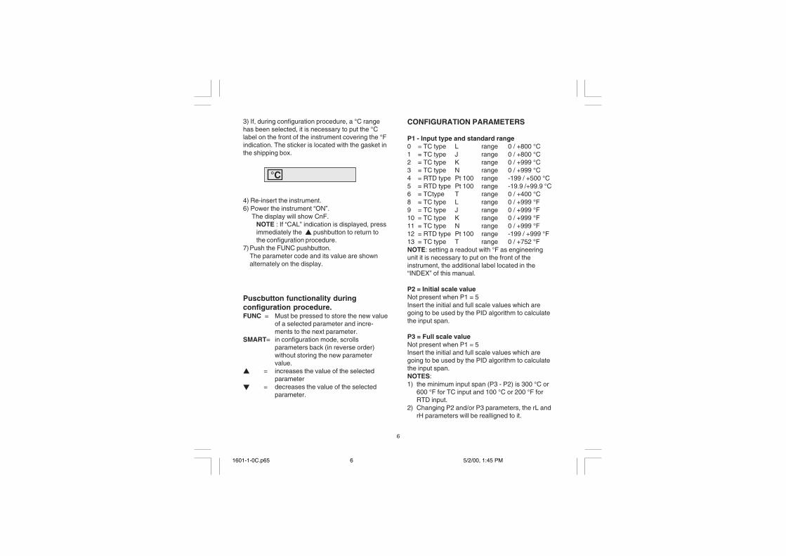
3) If, during configuration procedure, a °C rangehas been selected, it is necessary to put the °Clabel on the front of the instrument covering the °Findication. The sticker is located with the gasket inthe shipping box.
4) Re-insert the instrument.6) Power the instrument “ON”. The display will show CnF.
NOTE : If “CAL” indication is displayed, pressimmediately the � pushbutton to return tothe configuration procedure.
7)Push the FUNC pushbutton.The parameter code and its value are shownalternately on the display.
Puscbutton functionality duringconfiguration procedure.FUNC = Must be pressed to store the new value
of a selected parameter and incre-ments to the next parameter.
SMART= in configuration mode, scrollsparameters back (in reverse order)without storing the new parametervalue.
� = increases the value of the selectedparameter
� = decreases the value of the selectedparameter.
°C
1601-1-0C.p65 5/2/00, 1:45 PM6

7
P7 = Alarm actionAvailable only when P5 is different from 0 or 4.r = reverse (relay de-energized in alarm condition)d = direct (relay energized in alarm condition)
P8 = Alarm inhibitPresent only when P5 is different from 0 or 4.
OFF = inhibit disabledON = inhibit enabled
NOTE: If the alarm is programmed as band ordeviation alarm, this function disables the alarmcondition after a set point change or at thecontroller startup until the process variable passesthe alarm set point plus or minus hysteresis. If thealarm is programmed as process alarm, thisfunction disables the alarm condition at controllerstart up until the process variable pass the alarmset point plus hysteresis.
P9 = OFFSET applied to the measured valueThis OFFSET is applied along the whole range.When P1= 5 P9 is programmable from -19.9
to 19.9 °C.When P1 � 5 P9 is programmable from -199
to 199 °C or °F.
P4 = Main output actionr = reverse action (heating)d = direct action (cooling)
P5 = Output 2 functions0 = Not provided1 = Process alarm2 = Band alarm3 = Deviation alarm4 = instrument failure indicator (under or overrange, CJC, or A-D converter failure)
P6 = Output 2 operator mode.P6 is available only when P5 is different from 0.When P5 = 1,2 or 3H.A = high alarm (outside band) with automatic resetL.A = low alarm (inside band) with automatic resetH.L= high alarm (outside band) with manual reset
(latching)L.L= low alarm (inside band) with manual reset
(latching)
When P5 = 4 the selections H.A and L.A show aninstrument failure indicator with automatic reset whilethe H.L and L.L selections show an instrument failureindicator with manual reset.
t
INPUT
t
OUTPUT
t
INPUT
t
OUTPUT
Reverse Direct
Readout
P9
Real curve
adjusted curve
Input
1601-1-0C.p65 5/2/00, 1:45 PM7

8
P10 = Threshold of the “Soft Start” function.Enter the threshold value, in °C or °F, for the auto-matic start of the "Soft Start" function (limiting outputpower). If the unit powers up below the thresholdvalue, the "Soft Start" function is enabled and limitsthe power output to "OLH" for "tOL" minutes. "OLH"and "tOL" are set in operator mode.
P11 = User defined security code0 = device unlocked. All the parameters can be
modified1 = device locked. None of the parameters can be
modified except the SP.2 to 499 = Select the security code. During the
“operator mode”, the “software key”parameter will show one of the followingfigures:A) The device is “Unlocked”
and all parameters can bemodified.To make the device“Locked” insert a numberdifferent from the “securitycode”. Now none of theparameters can be modifiedexcept the SP.
B) The device is “locked” andnone of the parameters canbe modified except the SP.To “Unlock” the device,insert the “security code”.
500 to 999 = when selecting a security code betweenthese two numbers, the operation is identical toa selection from "2 to 499" except that both theset point and the alarm set point can be modi-fied.
P12 = Control output maximum rate of riseProgrammable from 1 % to 10 % of the output persecond.The ramp is applied when the controller changesthe percent of output desired. Above a 10 % thedisplay will show "InF" meaning that no ramp isimposed and the output immediatelychanges tothe PID calculated value.P12 not used if ON/OFF control selected.
P13 = Not used
ADVANCED CONFIGURATION
The configuration procedure is completed and theinstrument shows " -.-.-. " on both displays.When it is desired to end the configurationprocedure push the FUNC pushbutton; the displaywill show "CnF".
When it is desired to access to the advancedconfiguration parameter procede as follows:1) using � and � pushbutton set to 219.2) push the FUNC pushbutton.
1601-1-0C.p65 5/2/00, 1:45 PM8
9
P14 -Display of the operator parameters.This parameter is available only if P11 is differentfrom 0.This parameter allows you to enable/disable thedisplay of the protected parameters during"operator mode".OFF = protected parameters cannot be displayedON = protected parameters can be displayed
P15 - SMART function enabling/ disabling0 = The SMART function is disabled1 = The SMART function enabling/disabling is
NOT protected by the security code (P11).2 = The SMART function enabling/disabling is
protected by the security code (P11).
P16 - Maximum value of the proportional bandsettable by the SMART functionThis parameter may be programmed from P17orP18 value to 99.9.
P17 - Minimum value of the proportional bandsettable by the SMART function in heatingcontrol only.It may be programmed from 1.0% to P16 value.
P18 - Not Available
P19 - Not Available
P20 - Minimum value of integral time settableby SMART function.P20 is programmable from 00.1 (10 seconds) to02.0 (2 minutes).
P21 = Extension of the anti-reset-wind upRange: from -30 to +30 % of the proportionalband.NOTE: a positive value encreases the high limit ofthe anti-reset-wind up (over set point) while anegative value decreases the low limit of the anti-reset-wind up (under set point).
The advanced configuration procedure iscompleted and the instrument shows " CnF" onthe display.Pressing the "FUNC" will return the unit to the firstconfiguration parameter.
1601-1-0C.p65 5/2/00, 1:45 PM9
10
OPERATOR MODE
PRELIMINARYTo make the instrument operate as a controller theinternal switch V2 located on the input card (seeFig. 9) must be closed.
It is assumed, at this point, that the instrument hasbeen correctly configured as detailed in Section 3.The instrument shows the process value or the setpoint value (in this case the SP LED will beflashing). In order to toggle the indication push the� pushbutton. (this display condition is defined as“normal display mode”).
Pressing the FUNC pushbutton it is possible toscroll all the operator parameters.Instrument display alternates between parametercode and its value. During modification, only theparameter value will be displayed.To modify a parameter, first select the desiredparameter by the FUNC pushbutton, then set thenew value by � or � pushbuttons. Press FUNCpushbutton to store the new value and step to thenext parameter.NOTE: 1) If, during parameter modification, no
pushbutton is pressed for more than10 seconds, the instrument revertsautomatically to the “normal displaymode” and the new setting of the lastparameter will be lost.
2) The instrument doesn't display all theparameters.It selects the parameters inaccordance with:
a) The instrument configuration ingeneral (see chapter 3),
b) The P14 parameter in particular (seechapter 3),
c) The proportional band value (see page4.2).
INDICATORSSMART Flashing when the first part of the
SMART algorithm is active.Lit when the second part of the SMARTalgorithm is active.
OUT Lit when the OUT 1 is in ON condition.ALM Lit when the alarm 1 is in the alarm state.SP Flashing when the display shows the
control set point.
1601-1-0C.p65 5/2/00, 1:45 PM10
11
Pushbutton functions:FUNC = Stores the new value of the selected
parameter and goes to the nextparameter.
SMART = Enables or disables the SMARTfunction and scrolls back all theparameters without storing them.
� = Increases the value of the selectedparameter or toggles the displaybetween the set point value and themeasured value.
� = Decreases the value of the selectedparameter.
� + FUNC = Enables/disables the "LAMP TEST"
NOTE: a 10 seconds time out becomes opera-tional during parameter modification.If, during operator parameter modification, nopushbutton is pressed for 10 seconds, theinstrument reverts automatically to the “normaldisplay mode”. The new setting of the lastparameter modified is going to be memorized,prior to the time out, only if the FUNC pushbuttonwas depressed.
MANUAL RESET OF THE ALARMSIf the alarm has been configured as a latchedalarm, the alarm status persists after the alarmcondition disappears.To reset the alarm, push the FUNC pushbuttonand select the "n.rS" parameter (the display willshow "n.rS" and "OFF"). Using the � and �pushbuttons select "ON" and push the FUNCpushbutton again.The alarm cannot be reset until the alarmcondition has disappeared.
SMART ALGORITHMThe SMART feature automatically sets the bestcontrol action.To enable the SMART function, push the SMARTpushbutton for more than 1.5 s, when theinstrument is in normal display mode. The SMARTLED will light continuously or flash according tothe algorithm automatically selected.When the smart function is enabled, it is possibleto display but not to modify the control parameters(PB, TI, TD and rC).When the traditional control (PID) is desired, pushthe SMART pushbutton again (for more than 1.5 s)to turn the "SMART" OFF. The instrumentmaintains the "SMART" set of control parametersbut allows parameter modification.NOTES:1) The SMART function uses a derivative time equal
to 1/4 of the integral time.2) The limits of the proportional band set by the
SMART function are programmed by P16, P17and P18 parameters.
3) The lower limit of the integral time set bySMART function is programmed by P20parameter.
4) When ON/OFF control is programmed (PB=0),the SMART function is disabled.
5) The SMART enabling/disabling can beprotected by the security code (see P15parameter).
1601-1-0C.p65 5/2/00, 1:45 PM11

12
the instrument will automatically enable thisfunction again.
DIRECT ACCESS TO THE SET POINTMODIFICATIONThis feature allows the set point value to bemodified without using the FUNC pushbutton.When direct access to set point modification isrequired, proceed as follows:1) Push, for more than 3 seconds, the ��or �
pushbutton; the set point value, will bedisplayed and it will start to change.
2) Using the ��and � pushbuttons, it is possibleto set the desired value.
3) When the desired value is reached, do notpush any pushbutton for more than 3 second,the new set point will become operative after3 seconds.
If, during this procedure, there is no interest insaving the new value, push the FUNC pushbutton;the instrument will automatically return to thenormal display mode without having saved thenew set point.
DISPLAY OF THE SET POINT VALUETo display the programmed set point value pushthe � pushbutton.The display will show the set point value and thedecimal point of the last significant digit will flashto indicate that the number shown is the set pointvalue.To come back to display the measured value,push the � pushbutton again.
OUTPUT POWER OFFThe Output Power OFF feature turns off thecontrol and alarm output allowing modification ofparameters without affecting the process. With theoutput off the 1601 can be used as an indicator.To turn OFF the output signal, hold the �pushbutton first and then push FUNC pushbutton.After maintaining pressure on both of them formore than 3 seconds, the instrument will show"OFF" instead of the set point value.Since the 1601 has only one display, it is possibleto toggle from "OFF" to measured value bydepressing the � pushbutton.In the output power off condition the alarms are in noalarm condition (the alarm output status depends onthe type of alarm action programmed) and the pa-rameters can be reviewed and modified.When it is desired to come back to normal control,Hold the � pushbutton first and then push the FUNCpushbutton.Maintaining pressure on both of them for morethan 3 seconds, the instrument will return inNORMAL DISPLAY MODE.NOTES :1) If the output is turned OFF when the SMART
function was performing the first part of thealgorithm (LED SMART is flashing), theSMART function will be aborted and when theinstrument comes back to the normal control,the SMART function will be disabled.If the output is turned OFF when the SMARTfunction was performing the second part of thealgorithm (LED SMART is lit), the SMARTfunction will be stopped and, when theinstrument comes back to the normal control,the smart function also will be activated.
2) If the instrument is turned OFF with the outputpower off function enabled, at the next start up
1601-1-0C.p65 5/2/00, 1:45 PM12
13
LAMP TESTTo verify operation of the display LED, push �and FUNC together. The instrument LEDs willflash until the Lamp Test is turned off.
To turn off the Lamp Test, press � and FUNCtogether.
No other pushbutton functions are operable duringthe Lamp Test.
OPERATOR PARAMETERSThe following is a list of all the available controlparameters. Note that some parameters may notbe displayed according to the specific instrumentconfiguration.Push the FUNC pushbutton, the 1601 willalternately show the parameter and its value or thestatus (ON or OFF) of the selected parameter.Using � or � pushbutton it is possible to set thedesired value or the desired status.By pushing the FUNC pushbutton, the instrumentsaves the new value (or the new status) and goesto the next parameter.
Param. DESCRIPTIONSP Set point (in eng. units).
Range: from rL to rH.n.rS Manual reset of the alarms.
This parameter is available only when alatching alarm has been programmed.Set ON and push the FUNC pusbuttonto reset the alarms.
nnn Security code for parameter protection.This parameter is skipped if P11 = 0 or 1ON = the instrument is in LOCK conditionOFF = the instrument is in UNLOCK condi-tionWhen it is desired to switch from LOCKto UNLOCK condition, set a value equalto P11 parameter.When it is desired to switch fromUNLOCK to LOCK condition, set a valuedifferent from P11 parameter.
AL Alarm set point(in eng. units).This parameter is present if an alarm isconfigured.
1601-1-0C.p65 5/2/00, 1:45 PM13
14
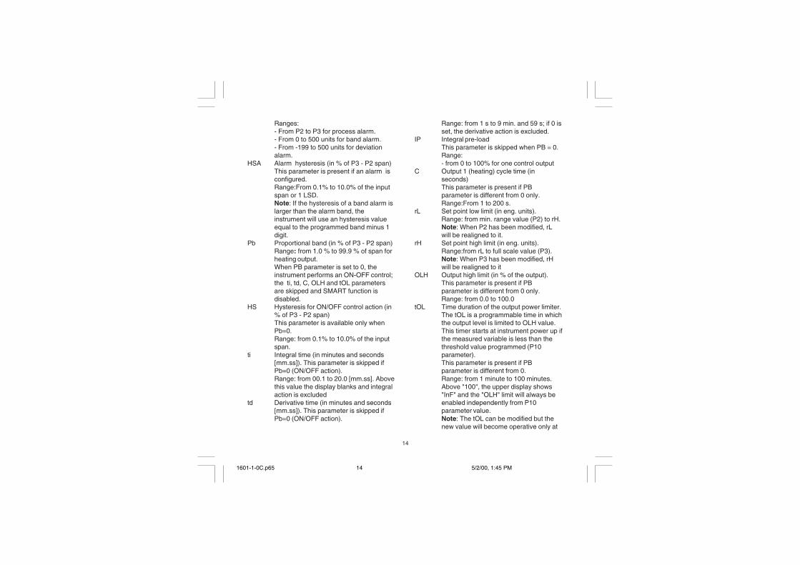
Ranges:- From P2 to P3 for process alarm.- From 0 to 500 units for band alarm.- From -199 to 500 units for deviationalarm.
HSA Alarm hysteresis (in % of P3 - P2 span)This parameter is present if an alarm isconfigured.Range:From 0.1% to 10.0% of the inputspan or 1 LSD.Note: If the hysteresis of a band alarm islarger than the alarm band, theinstrument will use an hysteresis valueequal to the programmed band minus 1digit.
Pb Proportional band (in % of P3 - P2 span)Range: from 1.0 % to 99.9 % of span forheating output.When PB parameter is set to 0, theinstrument performs an ON-OFF control;the ti, td, C, OLH and tOL parametersare skipped and SMART function isdisabled.
HS Hysteresis for ON/OFF control action (in% of P3 - P2 span)This parameter is available only whenPb=0.Range: from 0.1% to 10.0% of the inputspan.
ti Integral time (in minutes and seconds[mm.ss]). This parameter is skipped ifPb=0 (ON/OFF action).Range: from 00.1 to 20.0 [mm.ss]. Abovethis value the display blanks and integralaction is excluded
td Derivative time (in minutes and seconds[mm.ss]). This parameter is skipped ifPb=0 (ON/OFF action).
Range: from 1 s to 9 min. and 59 s; if 0 isset, the derivative action is excluded.
IP Integral pre-loadThis parameter is skipped when PB = 0.Range:- from 0 to 100% for one control output
C Output 1 (heating) cycle time (inseconds)This parameter is present if PBparameter is different from 0 only.Range:From 1 to 200 s.
rL Set point low limit (in eng. units).Range: from min. range value (P2) to rH.Note: When P2 has been modified, rLwill be realigned to it.
rH Set point high limit (in eng. units).Range:from rL to full scale value (P3).Note: When P3 has been modified, rHwill be realigned to it
OLH Output high limit (in % of the output).This parameter is present if PBparameter is different from 0 only.Range: from 0.0 to 100.0
tOL Time duration of the output power limiter.The tOL is a programmable time in whichthe output level is limited to OLH value.This timer starts at instrument power up ifthe measured variable is less than thethreshold value programmed (P10parameter).This parameter is present if PBparameter is different from 0.Range: from 1 minute to 100 minutes.Above "100", the upper display shows"InF" and the "OLH" limit will always beenabled independently from P10parameter value.Note: The tOL can be modified but thenew value will become operative only at
1601-1-0C.p65 5/2/00, 1:45 PM14

15
OVERRANGE, UNDERRANGE AND BURN-OUTINDICATIONSThe instrument shows the OVERRANGE andUNDERRANGE conditions with the followingindications:
Overrange Underrange
The sensor leads break can be signalled as:- for TC input : OVERRANGE or
UNDERRANGE If required seeChromalox for set up.
- for RTD input : OVERRANGE
Sensor leads short circuit detection:On RTD input, a special test is provided to signalOVERRANGE when input resistance is less than15 ohm (Short circuit sensor detection).
NOTE: When:- The instrument is set for one output only and an
OVERRANGE is detected, the OUT 1 turns OFF(if reverse action) or ON (if direct action).
- The instrument is set for one output only and anUNDERRANGE is detected, the OUT 1 turnsON (if reverse action) or OFF (if direct action).
NOTE: when an overrange or an underrange isdetected, the alarm operates as if amaximum or a minimum measurablevalue is present.
To eliminate the OUT OF RANGE condition,proceed as follows:
the next instrument start up.ERROR MESSAGES
1601-1-0C.p65 5/2/00, 1:45 PM15
16
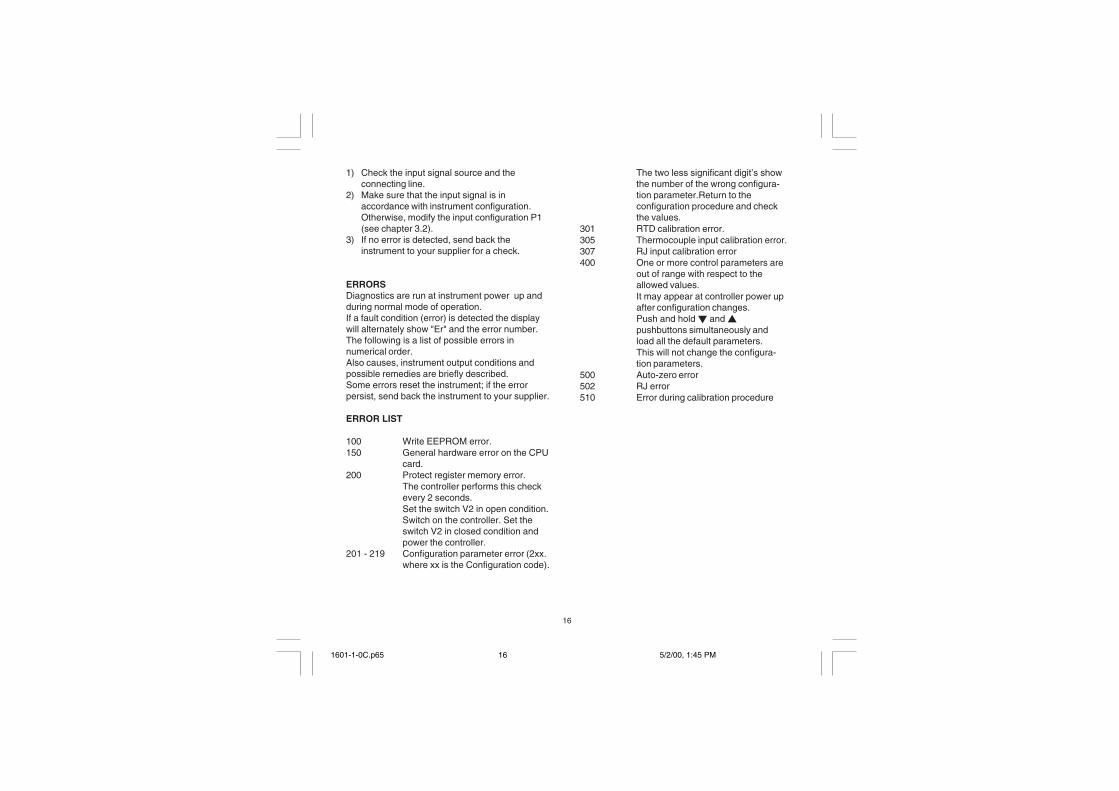
1) Check the input signal source and theconnecting line.
2) Make sure that the input signal is inaccordance with instrument configuration.Otherwise, modify the input configuration P1(see chapter 3.2).
3) If no error is detected, send back theinstrument to your supplier for a check.
ERRORSDiagnostics are run at instrument power up andduring normal mode of operation.If a fault condition (error) is detected the displaywill alternately show "Er" and the error number.The following is a list of possible errors innumerical order.Also causes, instrument output conditions andpossible remedies are briefly described.Some errors reset the instrument; if the errorpersist, send back the instrument to your supplier.
ERROR LIST
100 Write EEPROM error.150 General hardware error on the CPU
card.200 Protect register memory error.
The controller performs this checkevery 2 seconds.Set the switch V2 in open condition.Switch on the controller. Set theswitch V2 in closed condition andpower the controller.
201 - 219 Configuration parameter error (2xx.where xx is the Configuration code).
The two less significant digit’s showthe number of the wrong configura-tion parameter.Return to theconfiguration procedure and checkthe values.
301 RTD calibration error.305 Thermocouple input calibration error.307 RJ input calibration error400 One or more control parameters are
out of range with respect to theallowed values.It may appear at controller power upafter configuration changes.Push and hold � and �pushbuttons simultaneously andload all the default parameters.This will not change the configura-tion parameters.
500 Auto-zero error502 RJ error510 Error during calibration procedure
1601-1-0C.p65 5/2/00, 1:45 PM16

17
CALIBRATION
FIg. 11Dip switch location: To start calibration, V2 mustbe OPEN.
GENERAL GUIDELINES FOR CALIBRATION
NOTE:All 1601 are calibrated at the manufacturingplan. It is not necessary to calibrate the 1601on receipt.
For an good calibration it is necessary to proceedas follows:1) - The controller under calibration should be
mounted in its case in order to keep theinternal temperature stable.
2) - The ambient temperature should be stable.Avoid any drift due to air-conditioning, etc.
3) - The relative humidity should not exceed 70%.4) - Minimum warm-up time must be 20 minutes.5) - If possible, operate in a noise free environ-
ment6) - During calibration, connect one input at a time
to the rear terminal block.
+
+
1
3 42
PZ3
PZ4
PZ5
V2
B L4
C6
C10C5
C8
L3
L2C7
R7
R8
J6
J52
C14
C2 R4
R5
R11
Q2
R3
PZ2
PZ1
C15
K2
C9
��
WORNING:Do not attempt calibration without therecommended simulator or calibrator.
For this calibration procedure it is necessary touse calibrators with the following accuracy andresolution:
ACCURACY1) For TC input: + 0.005% output + 0.001% range
+ 5 �V2) For RTD input: + 0.02 % + 0.0025 �/decade.3) For cold junction compensation: better than 0.1
°C
RESOLUTION1) For TC input: 1 �V2) For RTD input: 10 m�3) For cold junction compensation: better than 0.1
°C
CALIBRATION PROCEDURECalibration parameters are logically divided ingroups of two parameter each (initial and finalscale value). After each group, the calibrationcheck is provided but it is also possible to bo thecheck without calibrating.
NOTE:Pushing the SMART pushbutton goes back to theprevious parameter without modifying thecalibration.
All the controllers are originally calibrated at thefactory by means of calibrators with high accuracyand resolution.
1601-1-0C.p65 5/2/00, 1:45 PM17

18
The following is a complete list of calibrationsymbols:
Code ParametertL TC input initial scale value (0 mV)tH TC input full scale value (50 mV)t. TC input checkrJ Cold junction compensationrJ. Cold junction compensation checkPL RTD input initial scale value (0 � )PH RTD input full scale value (300.00 � )P. RTD input check.
Now to proceed1) to start calibration, V2 must be OPEN (see Fig.
11).2) Switch on the controller. The display will show
"CnF".3) Push the � pushbutton, the display will show
"CAL".4) Push the FUNC pushbutton to display the first
calibration code.5) Depress FUNC pushbutton in sequence until
the desired calibration code is reached.
RTD Calibration only:If only calibrating RTDs, press FUNC until the "PL"
parameter is displayed and proceed to page 19(PL) for other instructions.
"tL" - TC INPUT- INITIAL SCALE VALUE1) Provide connections between calibrator and
controller under test as shown in fig. 12.2) The display will show "tL.F" (where "F" means
"OFF").2) Set calibrator to 0.000 mV.
3) Push � or � pushbutton, the display willchange to "tL.n" (where "n" means "On").
4) After 30 seconds, start calibration by pushingthe FUNC pushbutton.Only the decimal point of the last significantdigit will light to indicate that the controller isperforming the calibration routine.At the end of this calibration routine, thecontroller will go to the next step.
Fig. 12
"tH" - TC INPUT - FULL SCALE VALUE1) After "tL" is calibrated, the 1601will show "tH.F"
for the full scale value.1) Set the calibrator to 50.000 mV (full scale
value).2) Push � or � pushbutton, the display will
change to "tH.n".3) After 30 seconds, start calibration by pushing
FUNC pushbutton. Only the decimal point of thelast significant digit will light to indicate that thecontroller is performing the calibration routine.At the end of this calibration routine, thecontroller will go to the next step.
3
2 _
+
MillivoltGenerator
1601-1-0C.p65 5/2/00, 1:45 PM18

19
"t�" - TC INPUT CHECK1) The display will show "t." and the two most
significant digits of the measurement alternatelywith the remaining digits as shown in thefollowing figure:
The "tH" calibration is correct if the indicationshown is equal to "t.30" and "000" + 10 counts.
1) Check the zero calibration, by setting thecalibrator to 0.000 mV, the read-out must beequal to "t. 0" and "000" + 10 counts.
2) Check the half scale linearity by setting thecalibrator to 25.000 mV. The read-out must be"t.15" and "000" + 10 counts.NOTE: when it is desired to use a differentcheck point, the following formula describes theratio between the signal input and theinstrument read-out (in counts).
Instrument readout (in counts) = input value
50 (mV)30000•
3) If linearity is incorrect, repeat thermocouplecalibration.
4) Push FUNC pushbutton, the instrument will goto the next calibration group.
COLD JUNCTION CALIBRATIONNOTE: make sure that "tL" and "tH" parametersare correctly calibrated before "rJ" parametercalibration.
rJ - ACTUAL VALUEThe display will show "rJ.F" (where "F" means"OFF").
1) Measure the temperature close to terminals 2and 3 using an instrument with accuracy betterthan 0.1 °C (see Fig. 13).
Fig. 13
2) Wait for a few minutes to allow the temperatureto stabilize over the entire system (sensor,calibrator and instrument).
3) Using � or � push-button, set a value equal tothe temperature measured by the measuringdevice in a tenth of °C.
4) Start the calibration by pushing the FUNCpushbutton. Only the decimal point of the lastsignificant digit will light to indicate that thecontroller is performing the calibration routine.At the end of this calibration routine, thecontroller will go to the next calibration step.
Check symbol MSD (in counts)
remaining three digits
2
+
_
3
RT
D Measuringdevice
1601-1-0C.p65 5/2/00, 1:45 PM19

20
"rJ" - COLD JUNCTION COMPENSATIONCHECKThe "rJ" code and the temperature, in tenths of°C, measured by the CJ compensator areshown alternately on the display.
1) Make sure that the cold junction temperaturemeasured by the controller is equal to the valuemeasured by the measuring device.
2) Push FUNC pushbutton, the instrument will goto the next calibration parameter.
TC Calibration only:Thermocouple calibration is now complete, if RTDcalibration is not needed, press FUNC until "CAL"is displayed see step 5 at page 21
RTD INPUT CALIBRATION
"PL" - RTD INPUT - INITIAL SCALE VALUEThe display will show "PL.F" (where "F" means"OFF").
1) Connect a resistor box as shown in fig. 14.
Fig.142) Set 0.00 � on the resistor box.3) Push � or � pushbutton, the display will
change to "PL.n" (where "n" means "On").
4) After 30 seconds, start the calibration bypushing the FUNC pushbutton. Only thedecimal point of the last significant digit will lightto indicate that the controller is performing thecalibration routine. At the end of this calibrationroutine, the controller will go to the nextparameter.
"PH" - RTD INPUT - FULL SCALE VALUEThe display will show "PH.F" (where "F" means
"OFF").1) Set the resistor box to 300.00 �.3) Push � or � pushbutton, the display will
change to "PH.n" (where "n" means "On").4) After 30 seconds, start the calibration by
pushing the FUNC pushbutton. Only thedecimal point of the last significant digit will lightto indicate that the controller is performing thecalibration routine.At the end of this calibration routine, theinstrument will go to the next step.
"P." - RTD INPUT CHECKThe "P." code followed by the two mostsignificant digits and the remaining digits of themeasured value are shown alternately on thedisplay.3
2
1 Resistor Box
Check symbol MSD (in counts)
remaining three digits
1601-1-0C.p65 5/2/00, 1:45 PM20
21
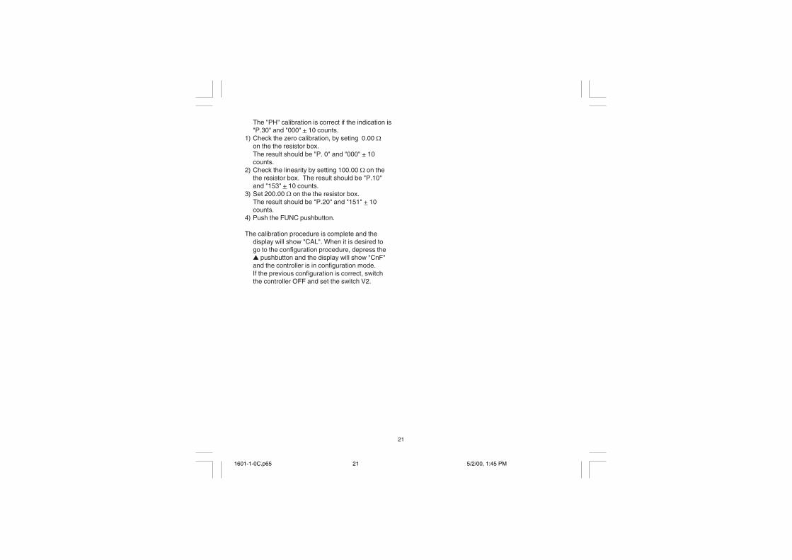
The "PH" calibration is correct if the indication is"P.30" and "000" + 10 counts.
1) Check the zero calibration, by seting 0.00 �on the the resistor box.The result should be "P. 0" and "000" + 10counts.
2) Check the linearity by setting 100.00 � on thethe resistor box. The result should be "P.10"and "153" + 10 counts.
3) Set 200.00 � on the the resistor box.The result should be "P.20" and "151" + 10counts.
4) Push the FUNC pushbutton.
The calibration procedure is complete and thedisplay will show "CAL". When it is desired togo to the configuration procedure, depress the� pushbutton and the display will show "CnF"and the controller is in configuration mode.If the previous configuration is correct, switchthe controller OFF and set the switch V2.
1601-1-0C.p65 5/2/00, 1:45 PM21

22
GENERAL INFORMATION
GENERAL SPECIFICATIONSCase: ABS grey color (RAL 7043); self-extinguish-
ing degree: V-0 according to UL 94.Front protection - designed and tested for IP 65 (*)and NEMA 4X (*) for indoor locations (when panelgasket is installed).(*) Test were performed in accordance with CEI 70-1 and NEMA 250-1991 STD.Installation: panel mounting by means of mountingbraket. Instrument removable from case.Rear terminal block:10 screw terminals ( screwM3, for cables from � 0.25 to � 2.5 mm2 or fromAWG 22 to AWG 14 ) with connection diagramsand safety rear cover.Dimensions: 48 x 48 mm, depth 100 mm (DIN43700).Weight: 160 g max.Power supply:- 100V to 240V AC 50/60Hz (-15% to + 10% of thenominal value).- 24 V AC/DC (+ 10 % of the nominal value).Power consumption: 6 VA max.Insulation voltage: 2300 V rms according toEN 61010-1.Display updating time: 500 ms.Sampling time: 500 ms.Resolution: 30000 counts.Accuracy (@ 25 °C): +0.3% of the input span +1 °C.Common mode rejection: 120 dB at 50/60 Hz.Normal mode rejection: 60 dB at 50/60 Hz.Electromagnetic compatibility and safetyrequirements: This instrument is marked CE.Therefore, it is conforming to council directives89/336/EEC (reference harmonized standardEN-50081-2 and EN-50082-2) and to councildirectives 73/23/EEC and 93/68/EEC (referenceharmonized standard EN 61010-1).
Installation category: IITemperature drift: < 200 ppm/°C (RJ excluded)< 400 ppm/°C for RTD input with -19.9/99.9 °C rangeand TC type T.Reference junction drift: 0.1 °C/°C.Operative temperature: from 0 to 50 °C (32 to122°F).Storage temperature : -20 to +70 °C (-4 to 158°F).Humidity: from 20 % to 85% RH, non condensing.Protections:1) WATCH DOG circuit for automatic restart.2) DIP SWITCH for protection against tamperingof configuration and calibration parameters.
INPUTSA) THERMOCOUPLEType: L, J, K, N, T programmable by frontpushbuttons.Line resistance: max. 100 � with error <+0.1% ofthe input span.Engineering unit: °C or °F programmable.Reference junction: automatic compensationfrom 0 to +50 °C.Reference junction drift : 0.1 °C/°C.Burn-out: Up or down scale selectable.Calibration: according to IEC 584-1 and DIN43710 - 1977 (TC L)STANDARD RANGES TABLE
TC
type
L
J
K
N
T
0 - +800 °C
0 - +800 °C
0 - +999 °C
0 - +999 °C
0 - + 400 °C
Measuring ranges
0 - +999 °F
0 - +999 °F
0 - +999 °F
0 - +999 °F
0 - +752 °F
1601-1-0C.p65 5/2/00, 1:45 PM22
23
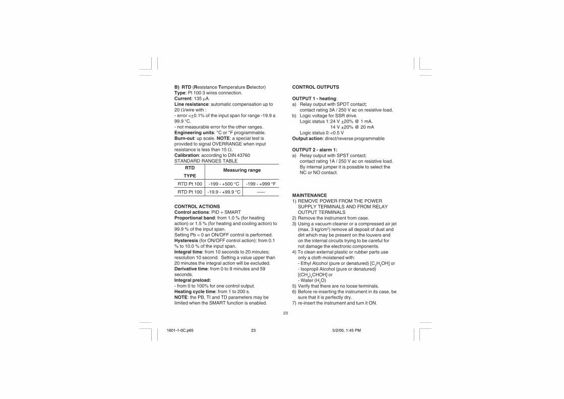
B) RTD (Resistance Temperature Detector)Type: Pt 100 3 wires connection.Current: 135 �A.Line resistance: automatic compensation up to20 �/wire with :- error <+0.1% of the input span for range -19.9 a99.9 °C.- not measurable error for the other ranges.Engineering units: °C or °F programmable.Burn-out: up scale. NOTE: a special test isprovided to signal OVERRANGE when inputresistance is less than 15 �.Calibration: according to DIN 43760STANDARD RANGES TABLE
CONTROL ACTIONSControl actions: PID + SMARTProportional band: from 1.0 % (for heatingaction) or 1.5 % (for heating and cooling action) to99.9 % of the input span.Setting Pb = 0 an ON/OFF control is performed.Hysteresis (for ON/OFF control action): from 0.1% to 10.0 % of the input span.Integral time: from 10 seconds to 20 minutes;resolution 10 second. Setting a value upper than20 minutes the integral action will be excluded.Derivative time: from 0 to 9 minutes and 59seconds.Integral preload:- from 0 to 100% for one control output.Heating cycle time: from 1 to 200 s.NOTE: the PB, TI and TD parameters may belimited when the SMART function is enabled.
CONTROL OUTPUTS
OUTPUT 1 - heating:a) Relay output with SPDT contact;
contact rating 3A / 250 V ac on resistive load.b) Logic voltage for SSR drive.
Logic status 1:24 V +20% @ 1 mA.14 V +20% @ 20 mA
Logic status 0:<0.5 VOutput action: direct/reverse programmable
OUTPUT 2 - alarm 1:a) Relay output with SPST contact;
contact rating 1A / 250 V ac on resistive load.By internal jumper it is possible to select theNC or NO contact.
MAINTENANCE1) REMOVE POWER FROM THE POWER
SUPPLY TERMINALS AND FROM RELAYOUTPUT TERMINALS
2) Remove the instrument from case.3) Using a vacuum cleaner or a compressed air jet
(max. 3 kg/cm2) remove all deposit of dust anddirt which may be present on the louvers andon the internal circuits trying to be careful fornot damage the electronic components.
4) To clean external plastic or rubber parts useonly a cloth moistened with:- Ethyl Alcohol (pure or denatured) [C2H5OH] or- Isopropil Alcohol (pure or denatured)[(CH3)2CHOH] or- Water (H2O)
5) Verify that there are no loose terminals.6) Before re-inserting the instrument in its case, be
sure that it is perfectly dry.7) re-insert the instrument and turn it ON.
RTD
TYPE
RTD Pt 100
RTD Pt 100
-199 - +500 °C
-19.9 - +99.9 °C
Measuring range
-199 - +999 °F
-----
1601-1-0C.p65 5/2/00, 1:45 PM23

A. 1
DEFAULT PARAMETERS
DEFAULT OPERATOR PARAMETERSThe control parameters can be loaded withpredetermined default values. These data are thetypical values loaded in the instrument prior toshipment from factory. To load the default valuesproceed as follows:
a) The internal switch should be closed.b) The SMART function should be disabled.c) The safety lock must be OFF.d) The display will show the process variable.e) Hold down � pushbutton and press �
pushbutton; the display will show:
f) Within 10 seconds press � or � pushbutton.The display will show:
g) Press FUNC pushbutton; the display will show:
This means that the loading procedure has beeninitiated. After about 3 seconds the loadingprocedure is terminated and the instrument revertsto NORMAL DISPLAY mode.
The following is a list of the default operativeparameters loaded during the above procedure:
PARAMETER DEFAULT VALUESP = minimum range-valuennn = OFFAL = minimum range-value for process alarms
0 for deviation or band alarmsHSA = 0.1 %PB = 4.0 %HS = 0.5 %ti = 04.0 (4 minutes)td = 1.00 (1 minute)IP = 30 % for one control output
0 % for two control outputsC = 20 seconds for relay output
2 seconds for SSR outputrL = initial scale valuerH = full scale valueOLH = 100 %tOL = infinite
d.O F
L. d t.
d.O n
1601-A-0C.p65 5/2/00, 1:45 PM1

A. 2
DEFAULT CONFIGURATIONPARAMETERSThe configuration parameters can be loaded withpredetermined default values. These data are thetypical values loaded in the instrument prior toshipment from factory. To load the default valuesproceed as follows:a) The internal switch (V2, see fig. 9) should be
open.b) The display will show:
c) Push the � pushbutton; the display will showthe firmware version.
d) Mantaining the pressure on the � pushbuttonpush the � pushbutton also.The instrument will show
e) Press � pushbutton to select between table 1(european) or table 2 (american) defaultparameter set. The display will show:
f) Press FUNC pushbutton; the display will show:
This means that the loading procedure has beeninitiated. After about 3 seconds the loadingprocedure is terminated and the instrument revertsto the "CnF" parameter).
The following is a list of the default parametersloaded during the above procedure:
PARAMETER TABLE 1 TABLE 2P1 1 9P2 0 °C 0 °FP3 400 °C 999 °FP4 r rP5 0 0P6 H HP7 r rP8 OFF OFFP9 0 0P10 0 0P11 0 0P12 10 10P13 2 2P14 ON ONP15 2 2P16 30.0 30.0P17 1.0 1.0P18 -- --P19 -- --P20 00.3 00.3P21 10 10
C n F
A. 0 1
d.F F
t b. 1
L. d t.
1601-A-0C.p65 5/2/00, 1:45 PM2
A. 3
Warranty And Limitation Of Remedy And Reliability
Chromalox warrants only that the Products and parts manufactured by Chromalox, when shipped, and the work performed byChromalox when performed, will meet all applicable specification and other specific product and work requirements (includingthose of performance), if any, and will be free from defects in material and workmanship under normal conditions of use. All claimsfor defective or non conform, (both hereinafter called defective). Products, parts or work under this warranty must be made inwriting immediately upon discovery, and in any event within three (3) years from delivery, provided, however all claims fordefective Products and parts must be made writing no later than three (3) years after shipment by Chromalox. Defective andnonconforming items must be held by Chromalox’s inspections and returned to the original f.o.b. point upon request. THEFOREGOING IS EXPRESSLY IN LIEU OF ALL OTHER WARRANTIES WHATSOEVER, EXPRESS, IMPLIED AND STATU-TORY, INCLUDING, WITHOUT LIMITATION, THE IMPLIED WARRANTIES OF MERCHANT ABILITY AND FITNESS FOR APARTICULAR PURPOSE.Not withstanding the provisions of this WARRANTY AND LIMITATIONS Clause it is specifically understood that Products andparts not manufactured and work not performed by Chromalox are warranted only to the extent and in the manner that the sameare warranted to Chromalox by Chromalox’s vendors, and then only to the extent that Chromalox is reasonably able to enforcesuch a warranty, it being understood Chromalox shall have no obligation to initiate litigation unless buyer undertakes to pay allcost and expenses therefore including but not limited to attorney’s fees and indemnifies Chromalox against any liability toChromalox’s vendors arising out of such litigation.Upon buyer’s submission of a claim as provided above and in its substantiation, Chromalox shall at its option either (i) repair orreplace its Products, parts or work at the original f.o.b. point of delivery or (ii) refund an equitable portion of the purchase price.The foregoing is Chromalox’s only obligation and buyer’s exclusive remedy for breach of warranty, and is buyer’s exclusiveremedy against Chromalox for all claims arising hereunder or relating hereto whether such claims are based on breach ofcontract, tort (including negligence and strict liability) or other theories, buyer’s failure to submit a claim as provided above shallspecifically waive all claims for damages or other relief, including but not limited to claims based on latent defects. In no eventshall buyer be entitled to incidental or consequential damages and buyer should hold Chromalox harmless therefrom. Any actionby buyer arising hereunder or relating hereto, whether based on breach of contract, tort (including negligence and strict liability)or other theories, must be commenced within three (3) years after the date of shipment or it shall be barred.
ReturnsItems returned to Chromalox Instruments and Controls must be accompanied by a Return Authorization Number. This numbermay be obtained from Chromalox Instruments and Controls, Customer Service Department. Telephone Number (615)793-3900.It should appear on the exterior of the shipping carton and on the shipping documents. Defective items will be repaired or replacedat our option, at no charge.
Return the defective part or product, freight prepaid, to:Chromalox Instruments and Controls1382 Heil-Quaker Blvd.LaVergne, TN 37086-3536
1601-A-0C.p65 5/2/00, 1:45 PM3
170.IU0.160.100
Chromalox�INSTRUMENTS AND CONTROLS
1382 HEIL QUAKER BOULEVARD
LAVERGNE, TN 37086-3536
PHONE (615) 793-3900
FAX (615) 793-3563
��������������� ����������������������� ����������������������� ����������������������� ����������������������� ��������EMERSON ELECTRIC CO.
1601-A-0C.p65 5/2/00, 3:37 PM4


