www.irf.com Page 1 of 26 IRAUDAMP12 REV 1.1 IRAUDAMP12 130W/4Ω x 2 Channel Class D Audio Power Amplifier Using the IR4301 By Jun Honda, Liwei Zheng CAUTION: International Rectifier suggests the following guidelines for safe operation and handling of IRAUDAMP12 Demo board; Always wear safety glasses whenever operating Demo Board Avoid physical contact with exposed metal surfaces when operating Demo Board Turn off Demo Board when placing or removing measurement probes
Transcript
www.irf.com Page 1 of 26 IRAUDAMP12 REV 1.1
IRAUDAMP12
130W/4Ω x 2 Channel Class D Audio Power Amplifier Using the IR4301
By
Jun Honda, Liwei Zheng
CAUTION:
International Rectifier suggests the following guidelines for safe operation and handling of IRAUDAMP12 Demo board;
Always wear safety glasses whenever operating Demo Board Avoid physical contact with exposed metal surfaces when operating Demo
Board Turn off Demo Board when placing or removing measurement probes
www.irf.com Page 2 of 26 IRAUDAMP12 REV 1.1
TABLE OF CONTENTS ........................................................ PAGE INTRODUCTION.................................................................................................................3
The IRAUDAMP12 reference design is a two-channel, 130W/ch (4Ω/±31V; no heatsink)/ 160W/ch (4Ω/±34V; *with heatsink) half-bridge Class D audio power amplifier. This reference design demonstrates how to use the IR4301 IC, implement protection circuits, and design an optimum PCB layout using PowIRaudio integrated Class D IC. This reference design does not require heatsink or fan cooling for normal operation (one-eighth of continuous rated power).The reference design provides all the required housekeeping power supplies for ease of use. The two-channel design is scalable for power and the number of channels.
Applications
AV receivers Home theater systems Mini component stereos Powered speakers Sub-woofers Musical Instrument amplifiers Car audio amplifiers
Features
Output Power: 130W x 2 channels (10%THD+N 4Ω load; no heatsink), 160W x 2 channels (10%THD+N 4Ω load; *with heatsink),
Multiple Protection Features: Over-current protection (OCP), high side and low side Over-voltage protection (OVP), Under-voltage protection (UVP), high side and low side DC-protection (DCP), Over-temperature protection (OTP)
PWM Modulator: Self-oscillating half-bridge topology with optional clock synchronization
Specifications
General Test Conditions (unless otherwise noted) Notes / Conditions ±15V~±31V Bipolar power supply; without heatsink
Supply Voltages ±15V~±34V Bipolar power supply; *with heatsink
Load Impedance 4-2Ω Resistive loadSelf-Oscillating Frequency 400kHz No input signal, Adjustable Gain Setting 26dB 1Vrms input yields rated power
Electrical Data Typical Notes / Conditions IR Devices Used IR4301 PowIRaudio integrated Class D IC Modulator Self-oscillating, second order sigma-delta modulation, analog input
100W 1kHz, 4Ω load, without heatsink 130W 1kHz, 4Ω load, *with heatsink 80W 1kHz, 3Ω load, without heatsink 95W 1kHz, 3Ω load, *with heatsink 55W 1kHz, 2Ω load, without heatsink
Output Power CH1-2: (1% THD+N)
70W 1kHz, 2Ω load, *with heatsink
www.irf.com Page 4 of 26 IRAUDAMP12 REV 1.1
130W 1kHz, 4Ω load, without heatsink 160W 1kHz, 4Ω load, *with heatsink 100W 1kHz, 3Ω load, without heatsink 120W 1kHz, 3Ω load, *with heatsink 70W 1kHz, 2Ω load, without heatsink
Output Power CH1-2: (10% THD+N)
90W 1kHz, 2Ω load, *with heatsink Rated Load Impedance 4-2Ω Resistive loadIdling Supply Current ±80mA No input signal Total Idle Power Consumption 4W No input signal Distortion 0.02% THD+N @ 50W, 4Ω Residual Noise 250V IHF-A weighted, AES-17 filter Channel Efficiency 96% Single-channel driven, 130W/*160W(*
with heatsink), Class D stage *Tested with heatsink from Digikey, part#:294-1085-ND with thermal pad BER161-ND
Connection Setup
Figure 1 Typical Test Setup
Volume
J6 J5
J3 J4
J7
R113
S3 S2
CH1 Output
CH2 Output
CH1 Input
CH2 Input
G
Protection
Normal
S1
15V~31V*, 5A DC supply
4 Ohm 4 Ohm
15V~31V*, 5A DC supply
250W, Non-inductive Resistors
J8
J9
Audio Signal Generator
IR4301
* With heatsink Power supplycan go up to +/-34V
SW1:PWM Shutdown/MUTE
www.irf.com Page 5 of 26 IRAUDAMP12 REV 1.1
Connector Description
CH1 IN J6 Analog input for CH1 CH2 IN J5 Analog input for CH2 POWER J7 Positive and negative supply (+B / -B) CH1 OUT J3 Output for CH1 CH2 OUT J4 Output for CH2 EXT CLK J8 External clock sync DCP OUT J9 DC protection relay output
Audio Precision-Setup
IRAUDAMP12 and Audio Precision shall be connected according to the Figureure below:
Figure 2
+ - + G - -
A B
-
CH1
CH1
A B
Gen
Power Supply
+/- 35V
CH2
+
+
Amp5
+
-
CH2
DB_209_Rev 2.0
4 Ohms4 Ohms
Audio PrecisionBal inputs
IR4301_DB
+/-31V*
AMP12
* With heatsink Power supplycan go up to +/-34V
www.irf.com Page 6 of 26 IRAUDAMP12 REV 1.1
Test Procedures
Test Setup:
1. Connect 4-250 W dummy loads to output connectors (J3 and J4 as shown onFigure 1) and parallel it with input of Audio Precision analyzer (AP).
2. Connect Audio Signal Generator to J6 and J5 for CH1 and CH2 respectively (Ap).3. Set up the dual power supply with voltages of ±15V~±31V (up to ±34V with
heatsink); set current limit to 5A.4. Set switch S1 to middle position (self oscillating).5. Set volume level knob R130 fully counter-clockwise (minimum volume).6. Connect the dual power supply to J7. as shown on Figure 1
Power up:
7. Turn ON the dual power supply. The ±B supplies must be applied and removed atthe same time.
8. Red LED (Protection) should turn on almost immediately and turn off after about 3s.9. Green LED (Normal) then turns on after red LED is extinguished and should stay on.10. Quiescent current for the positive supply should be 60mA 10mA at +31V.11. Quiescent current for the negative supply should be 80mA 10mA at –31V.12. Push S3 switch (Trip and Reset push-button) to restart the sequence of LEDs
indicators, which should be the same as noted above in steps 9-10.
Functionality Audio Tests:
13. Apply 1V RMS at 1kHz sinusoidal signal from the Audio Signal Generator.14. Turn control volume up (R130 clock-wise) to obtain an output reading of 250Watts.15. For all subsequent tests as shown on the Audio Precision graphs below (Figure 3-
Figure7), the measurements are taken across J3 and J4 with an AES-17 Filter.Observe that a 1 VRMS input generates an output around THD+N=1% power level.
16. Sweep the audio signal voltage from 15 mVRMS to 1 VRMS.17. Monitor the output signals at J3/J4 with an oscilloscope. The waveform must be a
non distorted sinusoidal signal with input signal below 1Vrms.
www.irf.com Page 7 of 26 IRAUDAMP12 REV 1.1
Performance and Test Graphs
Power vs THD+N
Test Conditions: VBus = ± 31V Input Signal = 1 KHz Load Impedance = 4 ohms Set Gain = 1% clipping 100W
ColorSweep Trace Line Style Thick Data Axis Comment
1 1 Blue Solid 2 Anlr.THD+N Ratio Left CH1 - 4 Ohms1 3 Magenta Solid 2 Anlr.THD+N Ratio Left CH2 - 4 Ohms
0.001
10
0.002
0.010.02
0.050.1
0.51
5
%
100m 200200m 500m 1 2 5 10 20 50 100
W
THD+N vs Power: Adjust pot level to 100W output with 1V rms level input
Figure 3
www.irf.com Page 8 of 26 IRAUDAMP12 REV 1.1
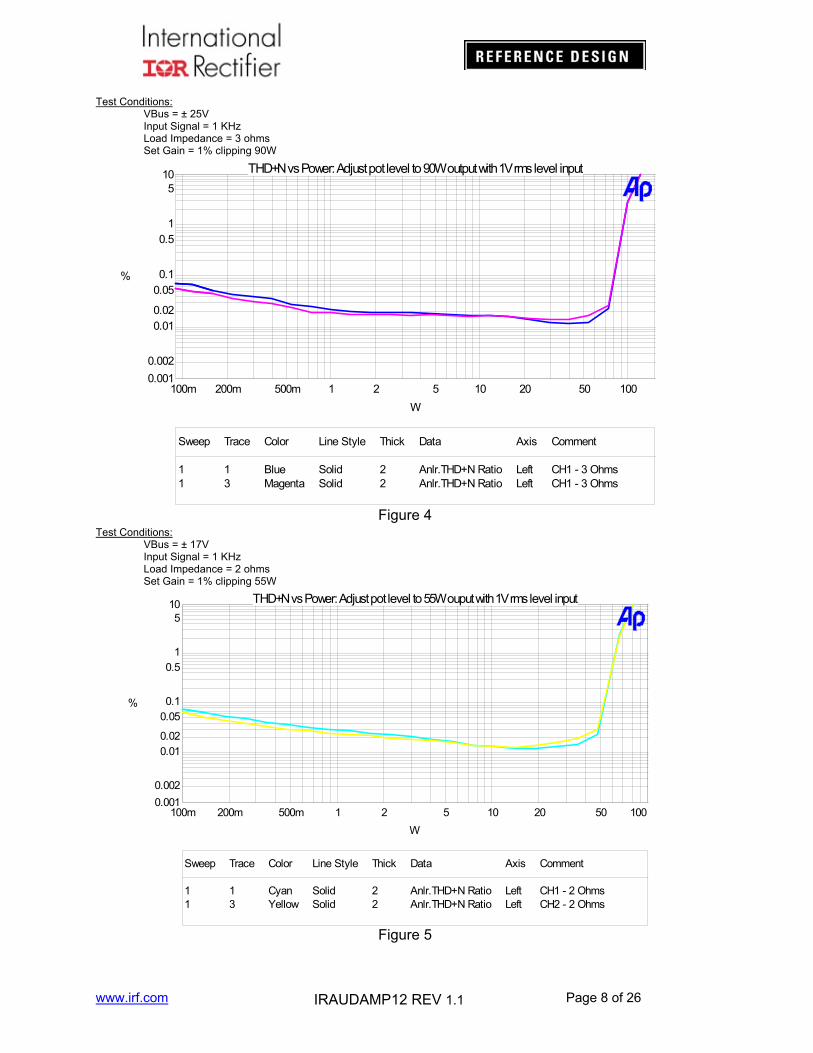
Test Conditions: VBus = ± 25V Input Signal = 1 KHz Load Impedance = 3 ohms Set Gain = 1% clipping 90W
ColorSweep Trace Line Style Thick Data Axis Comment
1 1 Blue Solid 2 Anlr.THD+N Ratio Left CH1 - 3 Ohms1 3 Magenta Solid 2 Anlr.THD+N Ratio Left CH1 - 3 Ohms
0.001
10
0.002
0.010.02
0.050.1
0.51
5
%
100m 100200m 500m 1 2 5 10 20 50
W
THD+N vs Power: Adjust pot level to 90W output with 1V rms level input
Test Conditions: VBus = ± 17V Input Signal = 1 KHz Load Impedance = 2 ohms Set Gain = 1% clipping 55W
ColorSweep Trace Line Style Thick Data Axis Comment
1 1 Cyan Solid 2 Anlr.THD+N Ratio Left CH1 - 2 Ohms1 3 Yellow Solid 2 Anlr.THD+N Ratio Left CH2 - 2 Ohms
0.001
10
0.002
0.010.02
0.050.1
0.51
5
%
100m 100200m 500m 1 2 5 10 20 50
W
THD+N vs Power: Adjust pot level to 55W ouput with 1V rms level input
Figure 4
Figure 5
www.irf.com Page 9 of 26 IRAUDAMP12 REV 1.1
Power vs THD+N (with heatsink)
Test Conditions: VBus = ± 34V Input Signal = 1 KHz Load Impedance = 4 ohms Set Gain = 1% clipping 130W
ColorSweep Trace Line S ty le Thick Data Axis Comment
1 1 Red Solid 2 S2.Anlr.THD+N Ratio Left CH1 4ohm 34V1 3 Blue Solid 2 S2.Anlr.THD+N Ratio Left CH2 4ohm 34V
0.001
10
0.002
0.005
0.01
0.02
0.05
0.1
0.2
0.5
1
2
5
%
100m 200200m 500m 1 2 5 10 20 50 100
W
Test Conditions: VBus = ± 27V Input Signal = 1 KHz Load Impedance = 3 ohms Set Gain = 1% clipping 95W
ColorSweep Trace Line Style Thick Data Axis Comment
5 1 Red Solid 2 S2.Anlr.THD+N Ratio Left CH1 3ohm 27V5 3 Blue Solid 2 S2.Anlr.THD+N Ratio Left CH2 3ohm 27V
0.001
10
0.002
0.005
0.01
0.02
0.05
0.1
0.2
0.5
1
2
5
%
100m 200200m 500m 1 2 5 10 20 50 100
W
Figure 6
Figure 7
www.irf.com Page 10 of 26 IRAUDAMP12 REV 1.1
Test Conditions: VBus = ± 19V Input Signal = 1 KHz Load Impedance = 2 ohms Set Gain = 1% clipping 70W
ColorSweep Trace Line Style Thick Data Axis Comment
1 1 Red Solid 2 S2.Anlr.THD+N Ratio Left CH1 2ohm 19V1 3 Blue Solid 2 S2.Anlr.THD+N Ratio Left CH2 2ohm 19V
0.001
10
0.002
0.005
0.01
0.02
0.05
0.1
0.2
0.5
1
2
5
%
100m 200200m 500m 1 2 5 10 20 50 100
W
Frequency Response
Test Conditions: VBus = ± 31V, 25V, 17V Set Output = 1V Load Impedance = 4, 3, 2 ohms
ColorSweep Trace Line Style Thick Data Axis Comment
1 1 Cyan Solid 2 Anlr.Level A Left Ch2 2ohm +-17V3 1 Yellow Solid 2 Anlr.Level A Left Ch2 4ohm +-31V4 1 Red Solid 2 Anlr.Level A Left Ch2 3ohm +-25V
-10
+4
-8
-6
-4
-2
+0
+2
dBr
A
20 200k50 100 200 500 1k 2k 5k 10k 20k 50k 100k
Hz
T T
Figure 9
Figure 8
www.irf.com Page 11 of 26 IRAUDAMP12 REV 1.1
Noise Floor
Test Conditions: VBus = ± 31V Load Impedance = 4 ohms Set Gain = 1% clipping No Input Signal
ColorSweep Trace Line Style Thick Data Axis Comment
1 1 Red Solid 1 Fft.Ch.1 Ampl Left Ch11 2 Blue Solid 1 Fft.Ch.2 Ampl Left Ch2
-140
+20
-120
-100
-80
-60
-40
-20
+0
dBV
10 20k20 50 100 200 500 1k 2k 5k 10k
Hz
Noise Floor with 1Vrms Output
Test Conditions: VBus = ± 31V Output = 1Vrms @ 1 KHz Load Impedance = 4 ohms Set Gain = 1% clipping
ColorSweep Trace Line Style Thick Data Axis Comment
1 1 Magenta Solid 1 Fft.Ch.1 Ampl Left Ch1 4ohm1 2 Red Solid 1 Fft.Ch.2 Ampl Left Ch2 4ohm
-100
+0
-80
-60
-40
-20
dBV
10 20k20 50 100 200 500 1k 2k 5k 10k
Hz
Figure 11
Figure 10
www.irf.com Page 12 of 26 IRAUDAMP12 REV 1.1
Efficiency
0.0%
10.0%
20.0%
30.0%
40.0%
50.0%
60.0%
70.0%
80.0%
90.0%
100.0%
0 20 40 60 80 100 120 140 160Power (W)
Eff
icie
ncy
Amp12 +/-31V 4ohms
Figure 12
www.irf.com Page 13 of 26 IRAUDAMP12 REV 1.1
Thermal Information
1) 1/8 Po Thermal information for IRAUDAMP12Conditions: Tamb=25°C natural convection cooling Both Channel Driven 1/8Po continuous 30minus Temperature measured by INFRARED Camera Measuring temperature point:
IR4301’s temperature saturated ≤85°C within 30minutes Figure 13
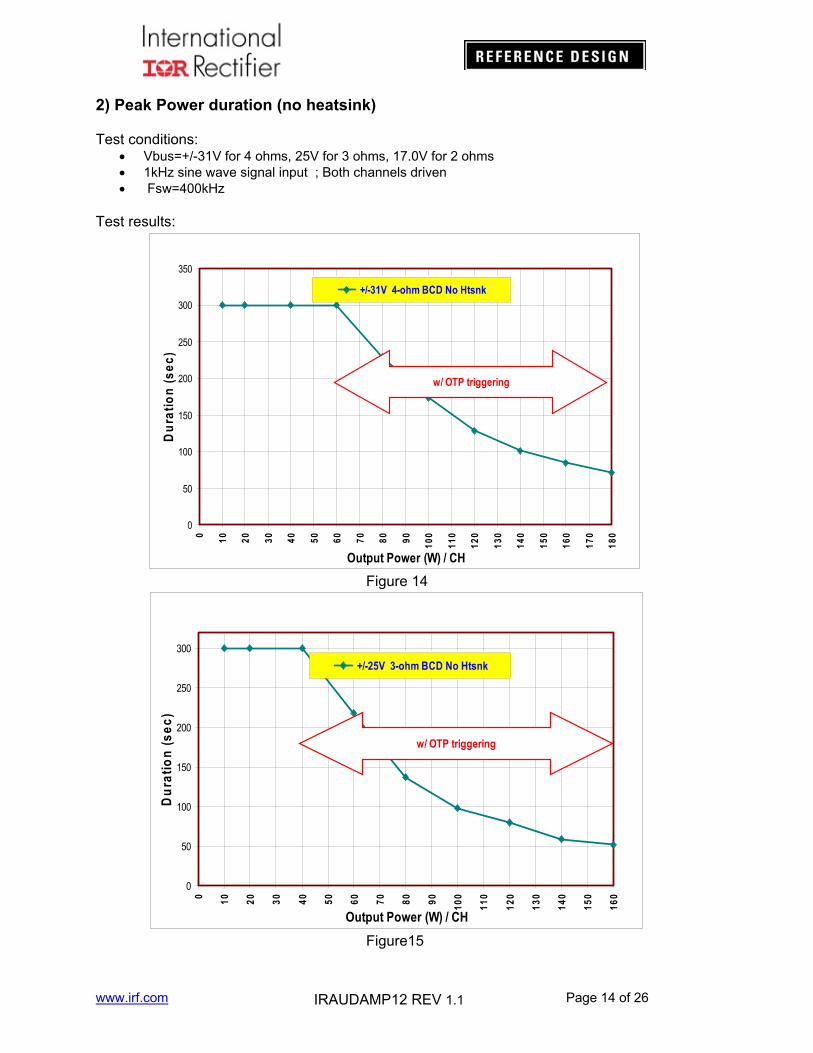
Test conditions: Vbus=+/-31V for 4 ohms, 25V for 3 ohms, 17.0V for 2 ohms 1kHz sine wave signal input ; Both channels driven Fsw=400kHz
Test results:
0
50
100
150
200
250
300
350
0
10
20
30
40
50
60
70
80
90
10
0
11
0
12
0
13
0
14
0
15
0
16
0
17
0
18
0
Output Power (W) / CH
Du
rati
on
(s
ec
)
+/-31V 4-ohm BCD No Htsnk
w/ OTP triggering
Figure 14
0
50
100
150
200
250
300
0
10
20
30
40
50
60
70
80
90
10
0
11
0
12
0
13
0
14
0
15
0
16
0
Output Power (W) / CH
Du
rati
on
(s
ec
)
+/-25V 3-ohm BCD No Htsnk
w/ OTP triggering
Figure15
www.irf.com Page 15 of 26 IRAUDAMP12 REV 1.1
020406080
100120140160180200220240260280300320340
0
10
20
30
40
50
60
70
80
90
10
0
11
0
Output Power (W) / CH
Du
rati
on
(s
ec
) +/-17V 2-ohm BCD No Htsnk
w/ OTP triggering
Figure 16
3) Peak Power duration (with heatsink)
Test conditions: Vbus=+/-34V for 4 ohms, 27V for 3 ohms, 19V for 2 ohms 1kHz sine wave signal input ; Both channels driven
Test results:
0
100
200
300
400
500
600
700
800
900
1000
0 10 20 30 40 50 60 70 80 90 100
110
120
130
140
150
160
170
180
190
200
210
220
Output Power (W) / CH
Du
rati
on
(s
ec)
+/-34V 4-ohm BCD 8.5C/W Htsnk
w/OTP triggering
Figure 17
www.irf.com Page 16 of 26 IRAUDAMP12 REV 1.1
0
100
200
300
400
500
600
700
800
900
1000
0 10 20 30 40 50 60 70 80 90 100
110
120
130
140
150
160
170
180
190
Output Power (W) / CH
Du
rati
on
(se
c)
+/-27V 3-ohm BCD 8.5C/W Htsnk
w/ OTP triggering
Figure 18
0
100
200
300
400
500
600
700
800
900
1000
0
10
20
30
40
50
60
70
80
90
10
0
11
0
12
0
13
0
14
0
Output Power (W) / CH
Du
rati
on
(se
c)
+/-19V 2-ohm BCD 8.5C/W Htsnk
w/ OTP triggering
Figure 19
www.irf.com Page 17 of 26 IRAUDAMP12 REV 1.1
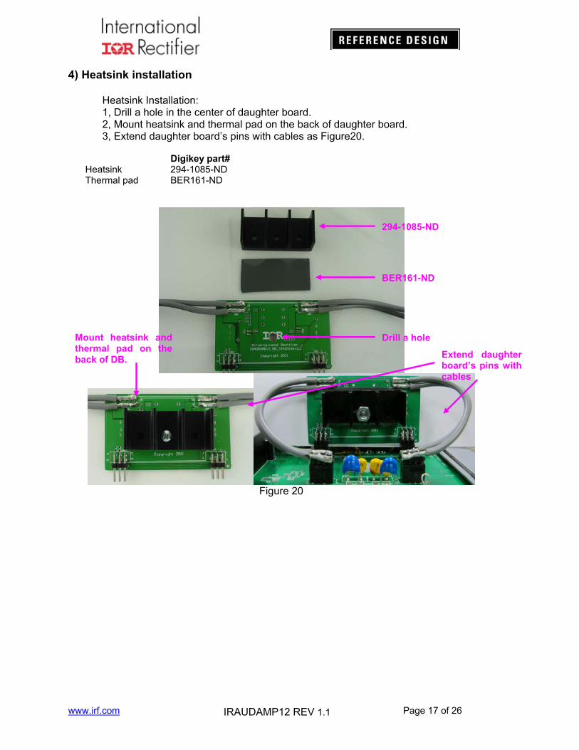
4) Heatsink installation
Heatsink Installation: 1, Drill a hole in the center of daughter board. 2, Mount heatsink and thermal pad on the back of daughter board. 3, Extend daughter board’s pins with cables as Figure20.
Digikey part# Heatsink 294-1085-ND Thermal pad BER161-ND
Figure 20
294-1085-ND
BER161-ND
Drill a hole Mount heatsink and thermal pad on the back of DB. Extend daughter
board’s pins with cables
www.irf.com Page 18 of 26 IRAUDAMP12 REV 1.1
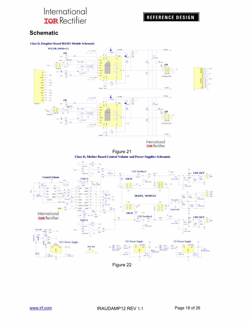
Schematic
D1 R1
100R
R3
10R
C210.1uF,100V
+B
-B
SD
VCC
R5
10RVSS
VAA
GND1
CH1
R174.7R
C170.1uF
R271R
C11
1nF
CH1 Output to LPF1
+31V Bus
-31V Bus
+5V
-5V
Audio Gnd 1
SD
-35V Bus
+31V Bus
VAAVSS
IN-1
CH1 O
+B
CH1
C13
10uF
C19
0.1uF,100V22uFC15
TP1
Class D, Daughter Board IR4301 Module Schematic
9101112
13141516
J2A
A26570-ND
123
456
J1A
A26568-ND
R7
2.7k
SCH_DB_4301Rev3.2
D2 R2
100R
R4
10R
C220.1uF,100V
+B
-B
SD
VCC
R6
10RVSS
VAA
GND2
CH2
R184.7R
C180.1uF
R281R
C12
1nF
+31V Bus
-31V Bus
+5V
-5V
Audio Gnd 2
SD
-35V Bus
+31V Bus
C14
10uF
C200.1uF,100V22uF
C16
R8
2.7kIN-2
GND2
Audio Gnd 2
SDVSSVCC7
89
101112
J1B
A26568-ND
CH2 Output to LPF2
-B
CH2TP2
1234
5678
J2B
A26570-ND
C3
2.2nF,50V
C5
2.2nF,50V
C4
2.2nF,50V
C6
2.2nF,50V
IN212
PWM13
VSS2
VCC10
SD11
OT1
VSS 8
PWM27
GND15
IN1 4
VAA6
GND29
J1
CON EISA31
SD
-B
+B
CH1 O
CH2 O
-B6
+B 15
GND16
-B7
CH1 O9
CH2 O1
CH2 O2
CH1 O 10
-B 5
CH2O3
CH2 O4
-B8
CH1 O11
CH1 O12
+B14
+B13
J2
VAA
CH2 O
VSS
IN-1
GND1
VSS
GND2
VCC
IN-2
C1 10uF, 16V
C2 10uF, 16V
C7 4.7uF,10V
C9 4.7uF,10V
C8 4.7uF,10V
C10 4.7uF,10V
D3
1N4148
D4
1N4148
R16
4.7R
R15
4.7R
R9 620R
R10 620R
-B
-B
R31
33K
R32
33K
IN+3
GND2
VAA1
VB
13
VP
12
COMP5
VN
10
VS 11
VC
C8
CSD6
IN-4
VSS7
CO
M9
CS
H14
O
15
U1
PQFN
D5
1N4148
D6
1N4148
IN+3
GND2
VAA1
VB
13
VP
12
COMP5
VN
10
VS11
VC
C8
CSD6
IN-4
VSS7
CO
M9
CS
H14
O
15U2
PQFN
-B
-B
Figure 21
J5
R5
4.7R
R13
3.3K12
J3
L122uH
R31
47k 1%
R58100K
J6
R4100R
R14
3.3K
R32
47k 1%
C321000uF,50V
C311000uF,50V
R57100K
C27
OPEN
C26
0.1uF, 400V
C28
OPEN
L222uH
R48
10, 1W
R34
1K
R33
1K
C18150pF, 500V
C17150pF, 500V
CH1 OUT
CH2 OUT
CH2 IN
CH1 IN
12
J4
C33OPEN
C34OPEN
R39
470
R40
470
R492.2k
R3100R
R1
100K
C210uF, 50V
C310uF, 50V
R2
100K
R6
4.7R
R7 47R
R8 47R
R9 10R
R10
47R
R11
47R
C110uF, 50V
R502.2k
R17
22k
R18
22k
C16
33pF
MUTE
C250.1uF, 400V
R47
10, 1W
C15
33pFU374AHC1G04
U474AHC1G04
C19
2.2uF,16V
C20
2.2uF,16V
R27
47R
R28
47R
C23
0.47uF, 400V
C24
0.47uF, 400V
-5V
+5V
+5V
+5V
C510uF, 50V
C610uF, 50V
+5V
CLK
CLK
D5
D7
D8
D6
-B
+B
-B
+B
-B
+B
CH1 O
+B
CH2 O
-BSD
IN-1
VCC
VCC
OC
IN-2
+5V-5V
-5V
VSS8
VR07
VR16
CLK5
VDD1
CS2
SDATA 3
SIMUL4
U_2
3310S06S
R10
8
C1074.7uF, 16V
C10810nF, 50V
SCLK
SDATAI
C109
4.7uF, 16V
CS
+5V
Control Volume R550.0
R560.0
IR430X_ MODULE
CH1 Feedback
CH2 Feedback
+5V Audio in
Audio in
ZM4732ADICT
Z102
4.7V
R104
47R, 1W
C10310uF, 50V
IN
GN
D
OUT
U_5 MC79M05
C102
10uF, 50V
R102
47R, 1W
C101
10uF, 50V
Vin
GN
D
Vout
U_4 MC78M05
ZM4732ADICT
Z101
4.7V D102MA2YD2300D101
MA2YD2300C104
10uF, 50V
R101
47R, 1W
R103
47R, 1W-B
-5V+5V
+B
C10510uF, 50V
R105
10R
C10610uF, 50V
Vin
GN
D
Vout
U_6MC78M12
Z103
12V
Q102
MM
BT
5401
R107
4.7K
R10647K
Z10415V
Q101FX941
VCC
+B
-B
HS1
VCC Power Supply +5V Power Supply -5V Power Supply
R71OPEN
R72
OPEN
Class D, Mother Board Control Volume and Power Supplies Schematic
123
456
J1A
789
101112
J1B
9101112
13141516
J2A
1234
5678
J2B
ZCEN1
CS2
SDATAI3
VD+4
DGRD5
SCLK6
SDATAO7
MUTE8
AINL16
AGNDR10
AOUTL 14
VA-13
VA+12
AOUTR11
AGNDL15
AINR9
U_?
CS3310
Trace under J7
Chassis Gnd
Heat Sink
VCC UVP
12
3
J7+35V
-35V
Gnd
+
-CH1
CH2+
-
Figure 22
www.irf.com Page 19 of 26 IRAUDAMP12 REV 1.1
PROTECTION
R12410k
R12147k
R12247k
CH
1 O
CH
2 O
Q106
MMBT5401
Q104
MMBT5401
C116
100uF, 16V
R14147k
NORMAL
R123
1K
Q108
MM
BT
5551
S1SW-PB
MUTE
123
654
P1
PVT412
12
J9
DC_PS
MUTE
Q105 MMBT5551
R12510K
R126100K
+B
Q109
MMBT5551
R139
47k
-B
SD
D105
1N4148
R138
4.7k
Z10618V
Z10711V
R14547K
R14647K
Q110MMBT5551
R144
10k
D1071N4148
D1061N4148
C117100uF, 16V
+5V
R14268k
+5V
R119
1k
R13668k
R13582k
1A
1Y
2A
2Y
3A
3Y
GND
VCC
6A
6Y
5A
5Y
4A
4Y
U_3
74HC14
R120100R
C114
10nF, 50V
+5V
I E SSW
S3ASW-3WAY_A-B
R1091K
R110
100k
C110
1nF, 50V
C1121200pF, 50VD103
1N4148
CLK
R11647R
CLK
IES
SWS3B
SW-3WAY_A-B
EXT. CLKA24497
J8BNCR115
47R
R114100R
R113
5K POT
R112820R
C111100pF, 50V
Q103
MMBT5551
21S2
SW_H-L
R11110K
C113
100pF, 50V
R13410k
R117
47R
R143
10K
SP M
UT
E
R118
1k
Trip and restart
R1296.8k
C115
10uF, 50V
-B
R14010k
Z105
36V
DC protection
OVP
R13247k
Q107
MMBT5551
D1041N4148
R13347k
DCP
DCP
R1276.8k
R1286.8k
R13047K
R13147K
R14810k
R14747k
Q111
MMBT5401
+B
R14947K
C1190.1uF, 50V
UVP
Z1088.2V
R137
47k
-5V
OT
OT
CStart
Q112MMBT5551
-5V +5V
Z1098.2V
R150
47k
R15147k
+B
Class D, Mother Board Clock and House Keeping Schematic
. Figure 23
www.irf.com Page 20 of 26 IRAUDAMP12 REV 1.1
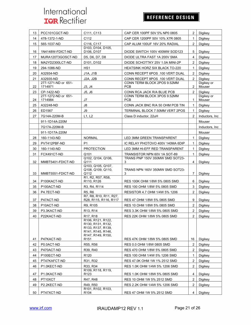
Bill of Materials
IRAUDAMP12 Daughter Board BOM
No Part Number Designator Description Quantity Vendor
1. Two Layers SMT PCB with through holes2. 1/16 thickness3. 2/0 OZ Cu4. FR4 material5. 10 mil lines and spaces6. Solder Mask to be Green enamel EMP110 DBG (CARAPACE) or Enthone Endplate
DSR-3241or equivalent.7. Silk Screen to be white epoxy non conductive per IPC–RB 276 Standard.8. All exposed copper must finished with TIN-LEAD Sn 60 or 63 for 100u inches thick.9. Tolerance of PCB size shall be 0.010 –0.000 inches10. Tolerance of all Holes is -.000 + 0.003”11. PCB acceptance criteria as defined for class II PCB’S standards.
www.irf.com Page 23 of 26 IRAUDAMP12 REV 1.1
Daughter Board
Figure 24
Figure 25
www.irf.com Page 24 of 26 IRAUDAMP12 REV 1.1
Mother Board
Figure 26
www.irf.com Page 25 of 26 IRAUDAMP12 REV 1.1
Figure 27
www.irf.com Page 26 of 26 IRAUDAMP12 REV 1.1
Revision changes descriptions
Revision Changes descriptionRev 1.0 Released Rev 1.1 Fig21’s Bus voltage has been corrected to
-31V
DateApr,30 2012 Feb,19 2014
WORLD HEADQUARTERS: 101 N. Sepulveda Blvd., El Segundo, California 90245 Tel: (310) 252-7105
Data and specifications subject to change without notice. 05/16/2012