60
Thermal Graphics Printers IPP 144 - 40 G IPP 144 - 40 GE Paper Reroll Mechanism IPP - AW USER`S MANUAL Version 6.10.12 or higher

Thermal Graphics PrintersIPP 144 - 40 G
IPP 144 - 40 GE
Paper Reroll MechanismIPP - AWWe reserve the right to make alterations! 09.12 Sach-Nr. 27866 88172
USER`S MANUALVersion 6.10.12 or higher
Exclusive agent for UK & Ireland:
Metrix Electronics LimitedElektronic Instrument Solutions for IndustryMinchens Court, Minchens Lane, Bramley,
Hampshire RG26 5BH, U.K.
Tel. +44 (0)845 03 43 234Fax: +44 (0)845 03 43 233
E-mail:[email protected]:www.metrix-electronics.com
GOSSEN Müller & WeigertZN der General Elektronik GmbH
Kleinreuther Weg 88D-90408 Nürnberg
Tel.: +49(0)911/3502-0 Fax: +49(0)911/3502-307E-mail: [email protected] Internet: www.g-mw.de
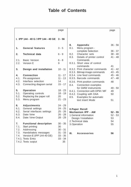
Table of Content s
page
I. IPP 144 - 40 G / IPP 144 - 40 GE 3 - 56
1. General features 3 - 5
2. Technical dat a 6 - 9
2.1. Basic Version 6 - 82.2. Version E 9
3. Design and installation 10 - 11
4. Connection 11 - 174.1. Pin assignment 11 - 134.2. Interface selection 144.3. Connecting diagram serial 15 - 17
5. Operation 18 - 235.1. Operating controls 18 - 195.2. Replacing the paper roll 205.3. Menu program 21 - 23
6. Adjustments 24 - 296.1. General settings 24 - 256.2. Serial interfaces settings 25 - 266.3. Date / time 26 - 286.4. Date / time Output 28 - 29
7. Functional description 30 - 357.1. Start printing 307.2. Addressing 30 - 317.3. Handshakes messages 31 - 337.4. Version E (IPP 144-40 GE) 33 - 357.4.1. Texts Entry 33 - 347.4.2. Texts output 35
page
8. Appendix 36 - 568.1. Menu program -
complete Selection 36 - 378.2. Character sets 38 - 408.3. Details of printer control 41 - 48
Commands8.3.1. Short view of control
commands 418.3.2. Print character commands 41 - 428.3.3. Bitmap image commands 43 - 458.3.4. Line feed commands 45 - 468.3.5. Barcode commands 47 - 488.3.6. Print position commands 488.4. Connection examples
for GMW instruments 49 - 508.4.1. Connection with DPM / MF 498.4.2. Coupling with DAA 508.5. Examples for automatic
text insert Mode 51
II.Paper RerollMechanism IPP - AW 52 - 551.General information 52 - 53
Design / Installation 532.Technical data 543.Operation 55
III. Accessories 56
1
III Accessories
♦♦♦♦♦ Paper reroll mechanism IPP - AW(incl. connection cable).
♦ Protection cover for use of IPP 144-40 G with IPP-AW,Protection class: IP 64.Dimensions: 155 x 155 [mm].Material: Plexiglas and
Santoprene 101-80 rubber
♦ Connection cable for serial data transmissionto the following devices:
IBM-PC XT and AT or compatiblesSiemens PG 685 (V 24)Siemens PG 675 / 685 (printer interface)Siemens GP270 /TP270/MP370 TOUCH(RS232C)(printer interface)Message displays:DAA 144-120B / 288-120B / 288-240B, Cothers on request.
Connection cable for USB-interface:USB-A connector - USB-B connector
♦ Windows programming software for IPP 144-40 GE version (CD-R)
56
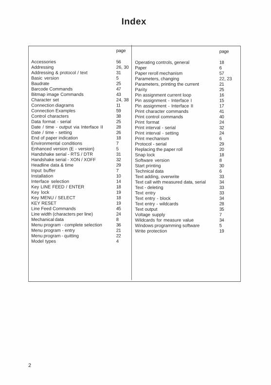
Index
page
Accessories 56Addressing 26, 30Addressing & protocol / text 31Basic version 5Baudrate 25Barcode Commands 47Bitmap image Commands 43Character set 24, 38Connection diagrams 11Connection Examples 59Control characters 38Data format - serial 25Date / time - output via Interface II 28Date / time - setting 26End of paper indication 18Environmental conditions 7Enhanced version (E - version) 5Handshake serial - RTS / DTR 31Handshake serial - XON / XOFF 32Headline data & time 29Input buffer 7Installation 10Interface selection 14Key LINE FEED / ENTER 18Key lock 19Key MENU / SELECT 18KEY RESET 19Line Feed Commands 45Line width (characters per line) 24Mechanical data 8Menu program - complete selection 36Menu program - entry 21Menu program - quitting 22Model types 4
page
Operating controls, general 18Paper 6Paper reroll mechanism 57Parameters, changing 22, 23Parameters, printing the current 21Parity 25Pin assignment current loop 16Pin assignment - Interface I 15Pin assignment - Interface II 17Print character commands 41Print control commands 40Print format 24Print interval - serial 32Print interval - setting 24Print mechanism 6Protocol - serial 29Replacing the paper roll 20Snap lock 18Software version 8Start printing 30Technical data 6Text adding, overwrite 33Text call with measured data, serial 34Text - deleting 33Text entry 33Text entry - block 34Text entry - wildcards 28Text output 35Voltage supply 7Wildcards for measure value 34Windows programming software 5Write protection 19
2
3. Operation
èèèèè Use the handle (4) to pull out the front panel (1).
è Remove the holder (3) with the paper from roll body,rotate the notch of the holder as show in the diagram.
è Remove the paper drum from the holder.
è Wind the paper once around the drum body (2) in thedirection indicated by the arrow.
è Plug in the holder (3) in such a way that the pins fitinto the notches of the body.
è Close the front panel.
è Briefly press the „LINE FEED“ key at theIPP 144 - 40 G until the paper has been straightenedout.
Removingthe paper
Insertingthe paper
55
I. IPP 144 - 40 G / IPP 144 - 40 GE
1. General features
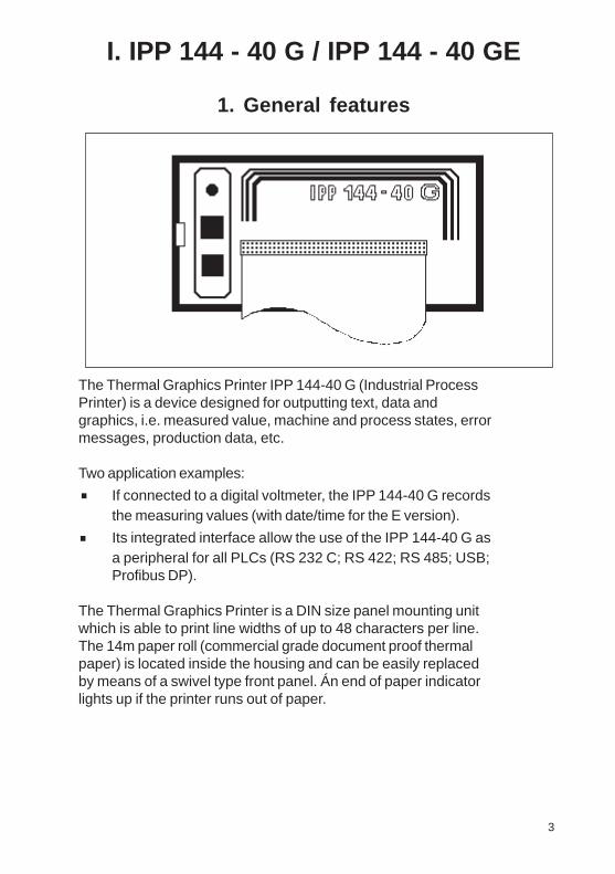
The Thermal Graphics Printer IPP 144-40 G (Industrial ProcessPrinter) is a device designed for outputting text, data andgraphics, i.e. measured value, machine and process states, errormessages, production data, etc.
Two application examples:
If connected to a digital voltmeter, the IPP 144-40 G recordsthe measuring values (with date/time for the E version).
Its integrated interface allow the use of the IPP 144-40 G asa peripheral for all PLCs (RS 232 C; RS 422; RS 485; USB;Profibus DP).
The Thermal Graphics Printer is a DIN size panel mounting unitwhich is able to print line widths of up to 48 characters per line.The 14m paper roll (commercial grade document proof thermalpaper) is located inside the housing and can be easily replacedby means of a swivel type front panel. Án end of paper indicatorlights up if the printer runs out of paper.
3
.
.
2. Technical dat a
Motor with friction clutch, electronic lag 3 sec
Paper width: max. 80 mmPaper length: max. 15 m
Store temperature range: -20 °C to +80 °COperating temperature range: 0 °C to +70 °CClimate: relative humidity
< 80 % up to 31 °C
Protection type housing: IP 50 acc. toEN 60528/VDE 0470
Mech.strength: To IEC 1010Safety: EN 61010-1:2001
CATIII >150V≤300VPollution degree 2
EMCSusceptibility: DIN EN 610004-1
to EN 610004-4Emission: DIN EN 50081-2
Class B
Dimensions (WxHxD): 144 x 72 x 159 mm
Connector: MASCON femalemulti point connector,4 pin keyed
Connector cable: AWG 26,approx. 100mm
Power supply: by IPP (5 V DC)
CE
The torque of the friction clutch has been factory adjustedand should not require adjustment.
The winding force of the motor can be adjusted by slightlyrotating the screw accessible through the left hand sidehole in the body:nnnnn less = turn leftnnnnn more = turn right
54
Winding
Ambientconditions
Standards
Miscellaneous
Connection
Maintenancefrictionclutch

Each printer is addressable, which allows the connection ofup to 31 devices to one sender device via a data line at theRS 485 interface, e.g. to a PLC.
4 53
Review of themodel types
There are two versions of the printer: The basic versionIPP 144-40 G with the Interface I and the enhanced versionIPP 144-40 GE with the Interfaces I and II.There are three option for the voltage supply: 12V DC (10V...19VDC) or 24V DC (19V...36V DC) or 110V/230V AC (switch-modepower supply: 85V...265V AC).InterfaceThere are four options for the Interface II:RS 232 C, RS 485, ProfiBus or USB
The connector for the Interface II of RS 232 C, RS 485 andProfiBus is a 9 pin D-Sub-socket. It is possible to change thisInterface card in the factory. The interface option USB has aspecial USB-B-socket. It is not possible to change thisinterface card with the other cards. Special adapter cablesand converters are used in this situation.
Model Supply V olt age Interface I Interface II
IPP 144-40 GIPP 144-40 GE 232IPP 144-40 GE 485IPP 144-40 GE PBIPP 144-40 GE USB
12V DC 24V DC 110/230V AC12V DC 24V DC 110/230V AC12V DC 24V DC 110/230V AC12V DC 24V DC 110/230V AC12V DC 24V DC 110/230V AC
Yes NoneYes RS 232 CYes RS 485Yes ProfiBusYes USB
Front Rear
1 Status indicator 2 Opening for paper feed3 Handle 4 Connector for connection5 Mounting screws cable IPP 144-40;6 Protective conductor connection (pin connections: Motor
(must be connected to ground) control, +5V, open, GND)7 Brightness LED
The paper reroll mechanism is inserted into the DIN sizepanel cutout from the front side and is clamped against therear of the switchboard using the mounting screws. Theswitchboard thickness must not exceed 12 mm.
Make sure that the unit is properly mountedbefore connection and power on.
Design
Installation
S P S
77777
Up to 32 printers

The enhanced version IPP 144 - 40 GE provides a second,bi-directional serial interface capable of outputting returnmessages under program control in compliance with a protocol.In addition, this model includes a text memory capable ofstoring up to 15 texts which are called by specifying thecorresponding text number. Moreover, date and time may beprinted with texts and data.It is not possible for the user to upgrade the basic version tothe enhanced version; as this is a different factory version.
EnhancedVersionIPP 144-40 GE
The basic version IPP 144-40 G provides one serial interfacecapable of receiving only. Return (handshake) messages tothe sender are sent via hardware line. Texts and measuringvalues to be printed must be transmitted from the sender devicesince the basic version does not have an internal text memory.It is possible to print with the basic version bitmap image andbarcodes. The bitmap image files and the barcode files aregenerated with printer control commands in a terminal emulationprogram.These files are transmitted by Interface I to the printer.
Basic V ersionIPP 144-40 G
A programming software for use with Microsoft Windows®operating systems has been developed.This software providesfunctions to progam the GE text memory, transfer user definedfonts or symbols and set the printer configuration parameters.Also this software package includes actual Windows® printerdrivers.The software will be shipped on CD-ROM.
MicrosoftWindows ®compatibleprogrammingsoftware
5
II Paper reroll mechanism IPP - AW
1. General information
The IPP-AW is a paper reroll mechanism designed for use with the ThermalGraphics Printer IPP 144-40 G. It has been designed to match the printer incolour and style. It is preferably installed directly underneath the printer. Theprinted paper is automatically wound on a drum by a motor. A front paneldraw allows easy paper handling.
The paper reroll mechanism is a DIN size panel mounting unit. It is suppliedwith power and controlled via connector cable which comes with the unit andwhich is connected to connector 12 of the IPP 144-40 G (see chapter 3.). AnLED indicates the ready status. Depending on the distance beween the twodevices at least the last 9 lines printed remain visible.
52
Print graphicsdirectly fromWindows ®
It is possible to print graphics, such as bmp-, jpg- or tif,directly from Windows® programs.Use a 24-pin type Windows® printer .The following configurations have been verified:Epson Combatible 24-pin andEpson LQ560.

51
2. Technical dat a2.1.Basic version
Printmechanism
Paper
Type of printing Fixed head thermal line
Character representation 576 dots/Line, 8 dots/mm
Print speed approx. 15 line/s (standard text mode)
Character/line 48 characters40 characters24 characters20 characters
Character height 2.5 mm at 48(40) characters 5 mm at 24 (20)characters
Character sets ASC II, german,french, danish, norwegian,swedish / finnish,spanish, english, cyrillic
Service life min. 10x106 Impulse or 50 km
Type commercial grade,document proofthermal paper
Width 80 mm (+0 / -1 mm)
Length approx. 14 m(approx. 4.600 line up to 48 characters per line)
Max. outer roll diameter 40 mm
Min. inner roll diameter 11,5 mm
Temperature standard paper: 0 °C to 60 °C
6
This mode can be used to print a group of texts, triggered by asingle <CR> input, even if no variable data is required to beinserted.NOTE: Text No. 7 is only pre-programmed with a variable data field.
8.5. Examples for automatic text insert mode
Example 1:Consignmentprint-out, withtime & date,marks andweights
Data input:10:15:33 15/10/03 <CR>1<CR> 123 <CR> 1 <CR> 1027<CR> 997 <CR> 30 <CR>Actual Print-out: Pre-stored texts
(„T“ = spaces reserved forvariable data)
10:15:33 15/10/2003 1 TTTTTTProduct Ref: 123 2 Product Ref: T T T T T TOperator No: 1 3 Operator No: T T T T T TGross: 1027 kg 4 Gross: T T T T T TNett: 997 kg 5 Nett: T T T T T TTare: 30 kg 6 Tare: T T T T T T
Six blocks of data are inserted and printed in sequence.
In this example, the IPP144-40 GE automatically adds date & timefrom its own real-time clock using the „PRINT DATE / TIME-HEAD-LINE“ menu option. Four blocks of variable data are sent to the printer.
Data input: 115<CR> 33.7<CR> 62.8<CR> 228.7<CR>Actual Print-out: Pre-stored texts
13.10.03 13:49:52Metrix Electronics Ltd. 1 Metrix Electronics Ltd.Rankine Road, Daneshill West 2 Rakine Road, Daneshill WestGB-Basingstoke RG24 8PP 3 GB-Basingstoke RG24 8PP
4Test Number: 115 5 Test Number: T T T T T T- - - TEST RESULTS - - - 6 - - - TEST RESULTS - - -Ambient Temp 33.7 °C 7 Ambient Temp TTTTTT°CBurn-in Temp 62,8 °C 8 Burn-in-Temp TTTTTT°CNom. Supply 230 Vac 9 Nom. Supply 230 VacActual 228.7 Vac 10 Actual TTTTTTVac
Example 2:Quality testprint-out, withseveralmeasuredvalue
Actual Printout: Pre-stored texts
15.10.2003 10:34:53Manufactured by:: 1 Manufactured by:
2Metrix Electronics Ltd. 3 Metrix Electronics Ltd.Rankine Road, Daneshill West 4 Rankine Road, Daneshill WestGB-Basingstoke RG24 8PP 5 GB-Basingstoke RG24 8PP__________________ 6 _________________
7 T T T T T T
All the texts up to Text No. 6 (without variable fields) are printed. Text No. 7(the first variable field) just prints a blank line. (If there was any variabledata sent before the <CR> this would be inserted and printed here.)
Example 3:A simple wayto print agroup of texts
The print-out is 10 texts - 4 with variable data inserted and 6 without.
Data input: <CR>
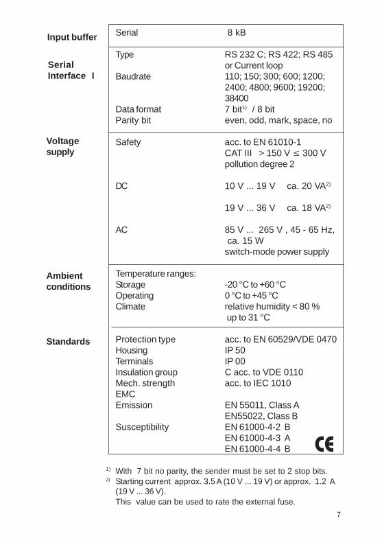
Serial 8 kB
Type RS 232 C; RS 422; RS 485or Current loop
Baudrate 110; 150; 300; 600; 1200;2400; 4800; 9600; 19200;38400
Data format 7 bit1) / 8 bitParity bit even, odd, mark, space, no
Safety acc. to EN 61010-1CAT III > 150 V ≤ 300 Vpollution degree 2
DC 10 V ... 19 V ca. 20 VA2)
19 V ... 36 V ca. 18 VA2)
AC 85 V ... 265 V , 45 - 65 Hz, ca. 15 Wswitch-mode power supply
Temperature ranges:Storage -20 °C to +60 °COperating 0 °C to +45 °CClimate relative humidity < 80 %
up to 31 °C
Protection type acc. to EN 60529/VDE 0470Housing IP 50Terminals IP 00Insulation group C acc. to VDE 0110Mech. strength acc. to IEC 1010EMCEmission EN 55011, Class A
EN55022, Class BSusceptibility EN 61000-4-2 B
EN 61000-4-3 AEN 61000-4-4 B
1) With 7 bit no parity, the sender must be set to 2 stop bits.2) Starting current approx. 3.5 A (10 V ... 19 V) or approx. 1.2 A
(19 V ... 36 V).This value can be used to rate the external fuse.
Input buffer
SerialInterface I
Volt agesupply
Ambientconditions
Standards
50
CE
7
8.4.2. Connection of IPP 144 - 40 G with a DAAmessage display to print fault messages
Messages can be sent by all DAA type B and C versions.(The A version DAA are not capable of outputting data butonly of displaying them since there is only one serial interfaceavailable which is used to receive data).
The connection of the printer is made via the Interface II(RS 232 C) of the DAA. The printout is normally triggered bya control device (e.g. a PLC) with a strobe signal (strobe T)via the terminal strip for control inputs (parallel interface) atthe DAA.
IPP 144-40 GDAA2
57
281
5TxD
CTS
GND
RxD
RTS
GNDSign.GNDStrobe T
Interface RS - 232 C:
DAA 144 - 120 B: 9 pin D - SUB 9 pin D - SUBDAA 288 - 120 B: 25 pin D - SUBDAA 288 - 240 B, C: 25 pin D - SUB
The required connection cable is available as an accessory.

Voltage supply connector Screw type/terminalsWire diameters fixed: 0,2 to 4 mm²
flexible: 0,2 to 2,5 mm²AWG: 24 to 12
Interface I 9 pin D-Sub socket
Interface II 9 pin D-Sub socketorUSB-B socket
Connection for paperreroll mechanism 4pin MASCON, MLAS
Connection forAlarm relay output Screw type/terminal
fixed: 0,2 to 4 mm²flexible: 0,2 to 2,5 mm²AWG: 24 to 12normally open50 V AC, 2 A30 V DC, 2 A
Dimensions(W x H x D) 144 x 72 x 159 mm
Switchboard mounting screws against rear sideof switchboard
Internal fuse( on power supply board) 12V DC : T 3,15 A
24V DC : T 2 A110V - 230V AC : T 2 A
This operating manual applies to software version6.10.12 and higher
49
Connections
Miscellaneous
8
8.4. Connection examples forGossen Müller & Weigert instruments
8.4.1. Connection of the IPP 144-40 GE to the DPM-MFfor the insertion of measured value into texts
For this configuration you must input and save the text as shown in section7.4.1. of this manual.The printer receives the measuring values via Interface I / RS 232 C (alsopossible via Interface II). To selected the text see section 7.4.2 in this manual.The relevant interface is the interface for which the parameters have to be setin the menu program. The recommended configuration is: 8 data bits, noparity, 1 stop bit, 9600 baud. With 7 bit, no parity, the sender must be set to2 stop bits.
DPM...MF IPP 144-40 GETxD
CTS
GND
OC 1OC 2
3
4
6
5
7
2
8
1
5
RxD
RTS
GND
Sign.GND
Interface I

2.2. Version E
Type RS 232 C or RS 4851)
ProfiBus or USBBaudrate 110; 150; 300; 600; 1200;
2400; 4800; 9600; 19200; 38400Data format 7 bit2) / 8 bitParity bit even, odd, mark, space, no
separate configurationby Interface II
Type flash memory
Memory size 600 Byte = 15 texts
Type CMOS, battery buffered3)
Accuracy ± 10 ppm = 0,8 sec / day
1) Please specify when ordering; if nothing is specified, RS 232 C issupplied.
2) With 7 bit no parity, the sender must be set to 2 stop bits .3) Lithium battery: 3 V
type: VARTA CR 2/3 AA Typ 6237PANASONIC BR 2/3 A 1 P
This product contains a Lithium battery which must not becut open, incinerated, exposed to temperature above+60 °C or recharged.Dispose of in accordance with national regulations.
^
^
SerialInterface II
Text entry fortexts to bestored
Text memory
Internal clock
Warning !
48 9
n START BYTE BAR CODE TYPE 0 No Start-Byte UPC-A 1 No Start-Byte UPC-E 2 No Start-Byte EAN 13 3 No Start-Byte EAN 8 4 No Start-Byte Code 39 5 No Start-Byte Interleaved 2/5(ITF) 6 No Start-Byte Codabar 7 135 Code 128A 7 136 Code 128B 7 137 Code 128 C
Printsbarcode
Command: GS k n (Start) <data>NUL<< Code >>0x1D , 0x6B , n,(Start)<data> 00H (0≤n≤7)
<< Function >>Selects a barcode system and prints barcodes.
In the case of GS k n:
8.3.6. Print position commands
Specifiesabsoluteposition
Command: ESC $ nL nH<< Code >>0x1B , 0x24, nL , nH (0≤nL≤255 , 0≤nH≤255)
<< Function >>Specifies the next print start position as an absolute positionbased on the left margin position.The next print start position is (nL + nH x 256) dots awayfrom the left margin position.
<< Details >>A print start position specified outside the print area isignored.
10
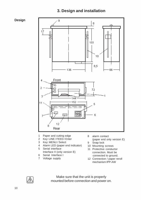
3. Design and installation
Design
1 Paper and cutting edge2 Key: LINE / FEED / Enter3 Key: MENU / Select4 Alarm LED (paper end indicator)5 Serial interface
Interface II (only version E)6 Serial Interface I7 Voltage supply
8 alarm contact(paper end only version E)
9 Snap lock10 Mounting screws11 Protective conductor
connection. Must be connected to ground.12 Connection / paper reroll
mechanism IPP-AW
Make sure that the unit is properlymounted before connection and power on.
47
Front
Rear
8.3.5. Barcode commands
Selectsprintingposition ofHRI character
<< Details >>HRI refers to Human Readable Interpretation.
Command: GS H n<< Code >>0x1D , 0x48 , n (0≤n≤3, initial value n=0)
<< Function >>Selects the print position of HRI characters when printing a barcode.
Setsbarcodeheight
Command: GS h n<< Code >>0x1D , 0x68 , n (1≤n≤255 , initial value n=128)
<< Function >>Sets barcode height to n dots.
Sets widthof barcode
n PRINTING POSITION
0 Not printed (Default)
1 Above bar code
2 Under bar code
3 Above and under bar code
Command: GS w n<< Code >>0 x 1D , 0 x 77 , n ( 2≤n≤6 , initial value n=3)
<< Function >>Specifies barcode width.
11
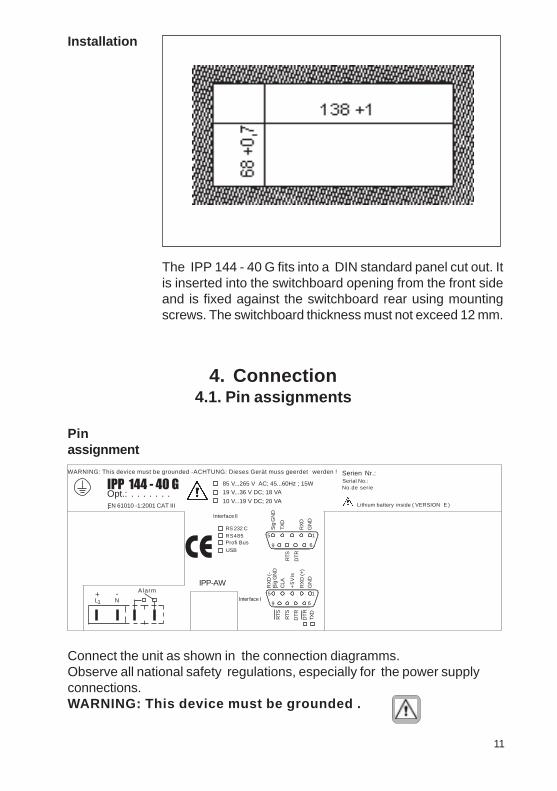
Installation
The IPP 144 - 40 G fits into a DIN standard panel cut out. Itis inserted into the switchboard opening from the front sideand is fixed against the switchboard rear using mountingscrews. The switchboard thickness must not exceed 12 mm.
46
4.1. Pin assignments
Pinassignment
4. Connection
Connect the unit as shown in the connection diagramms.Observe all national safety regulations, especially for the power supplyconnections.WARNING: This device must be grounded .
WARNING: This device must be grounded -ACHTUNG: Dieses Gerät muss geerdet werden !
IPP 144 - 40 GOpt.: . . . . . . ..
Alarm
L N1+ -
Serien Nr.:Serial No.:No.de serie
Lithium battery inside ( VERSION E )
CEIPP-AW
10 V...19 V DC; 20 VA
19 V...36 V DC; 18 VA
Interface II
Interface I1
6
RS 232 CRS485Profi BusUSB
1
Sig
GN
D
RX
D (+
)
5
9
RTS
RTS
DT
R
DT
RTX
D
CLA
+5
Vis
GN
D
RX
D (-
)
6
5
9
RTS
DT
R
Sig
GN
D
TXD
RX
D
GN
D
85 V...265 V AC; 45...60Hz ; 15W
EN 61010 -1:2001 CAT III
Setsline feed
Command: ESC 3n<< Code >>0x1B , 0x33 , n (0≤n≤25 , initial value n=60)
<< Function >>Sets the amount of line feed per line to n dot.
<< Details >>Line feed can be set separately for the standard mode.

12 45
SerialInterface I
Pin Signal
1 GND Ground (shield)
2 RXD (+) Receive data
3 +5 V Output +5 V / 20 mA
4 n.c.
5 RXD (-) Signal ground
6 DTR Open collector; active ifDTR is +8 V
7 DTR (Data Terminal Ready)+8 V: ready to receive-7 V: not ready to receive
8 RTS (Request To Send)+8 V: ready to receive-7 V: not ready to receive(text buffer is full)
9 RTS Open Collector; active ifRTS is +8 V
The serial Interface I has been designed to allow theimplementation of all widely used interfaces:RS 232 C; RS 422; RS 485 and Current loop.See chapter 4.3.: Connecting diagram
The required total number of bitmap image data is ((nL + nH x 256) x no. of data per line) bytes.The format of bitmap data for a printer with n heatingelements in the head is as follows:
MSB LSB
d1 d2 d3 ...... d (n/8)
d (n/8)+1 d (n/8)+2 d (n/8)+3 ...... d (2n/8)
d (2n/8)+1 d (2n/8)+2 d (2n/8)+3 ...... d (3n/8)
:: .......
d (nL+nHx256)x(n/8)
Sets initialline feed
8.3.4. Line feed commandsCommand: ESC 2<< Code >>0x1B , 0x32
<< Function >>Sets the amount of the initial line feed per line to 30 dots.
<< Details >>:The amount of the initial line feed can be set separately forthe standard mode.

1344
SerialInterface II(only IPP 144 -40 GE)
Pin Signal
1 GND Ground (shield)
2 RXD (+) Receive data
3 n.c.
4 TXD Transmit data
5 RXD (-) Signal ground
6 n.c.
7 DTR (Data Terminal Ready)+8 V: ready to receive-7 V: not ready to receive
8 RTS (Request To Send)+8 V: ready to receive-7 V: not ready to receive
9 n.c.
This interface can either be operated under hardwarehandshake (DTR, RTS) or software handshake(XON / XOFF - Protocol). This does not require specialsettings.
See chapter 4.3.: Connecting diagram
PrintsbarcodePrintsbarcode
Bitmap-Data format
Dot Col.1 Col.2 Col.n 1 MSB : d1 d4 .... d 3n-2 8 9 : d2 d5 .... d 3n-11617 : d3 d6 .... d 3n LSB24
d 3(n+1)-2 d 3(n+2)-2 .... d 6n-2
d 3(n+1)-1 d 3(n+2)-1 .... d 6n-1
d 3(n+1) d 3(n+2) .... d 6n
Command: ESC A* nL nH d1 dk<< Code >>0x1B , 0x41 , 0x2A , nL , nH , d1 dkwhere: 0≤nL≤255 , 0≤nH≤255, 0≤d≤255
Prints rasterbitmap image
<< Details >>This command is effective only if this command is enteredat the start position of a line in the standard mode.d refersto bitmap image data. The bit for the dot to be printed is„1“ and the bit for the dot not to be printed is „0“.Therequired number of image data per line is as followsdepending on the number of heating elements in the head:
dots of heating element 192 dots 288 dots 384 dots 576 dots No. data per line 24 bytes 36 bytes 48 bytes 72 bytes
<< Function >>Specifies the raster bitmap image specified with(nL + nH x 256) lines in the vertical direction.
14 43
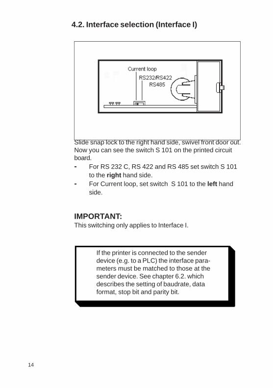
Slide snap lock to the right hand side, swivel front door out.Now you can see the switch S 101 on the printed circuitboard.- For RS 232 C, RS 422 and RS 485 set switch S 101
to the right hand side.- For Current loop, set switch S 101 to the left hand
side.
IMPORTANT:This switching only applies to Interface I.
If the printer is connected to the sender device (e.g. to a PLC) the interface parameters must be matched to those at the sender device. See chapter 6.2. which describes the setting of the baudrate, data format, stop bit and parity bit.
4.2. Interface selection (Interface I)
If the printer is connected to the senderdevice (e.g. to a PLC) the interface para-meters must be matched to those at thesender device. See chapter 6.2. whichdescribes the setting of baudrate, dataformat, stop bit and parity bit.
8.3.3. Bitmap image commandsPrints columnbitmap image
Command: ESC *m nL nH d1 dk<< Code >>
0x1B , 0x2A , m , nL , nH , d1 dkwhere: m=0, 32, 0≤nL≤255 , 0≤nH≤3, 0≤d≤255
<< Function >>Specifies a bitmap image in mode m for the number of dotsspecified by nL and nH.
m Mode No. of No. ofvertical dots Data (K)
0 8-dot single density 8 dots nL+nHx256 1 8-dot double density 8 dots nL+nHx25632 24-dot single density 24 dots (nL+nHx256)x333 24-dot double density 24 dots (nL+nHx256)x3
<< Details >>Processes the data after nL as normal data if m is outsidethe definable range.nL and nH denote the number ofhorizontal dots of the bitmap image to be printed, which is(nL+nHx256).
If bitmap image data exceeding the number of printabledots in a line is entered, the excess data is discarded.d denotes bitmap image data. The bit for the dot to beprinted is „1“ and the bit the dot not to be printed is „0“.Returns to normal data processing after bitmap imageprocessing.Has no effect on print modes (underline, character size)excluding NORMAL.Prints the entered bitmap image magnified three times inthe vertical direction if m=0 or 1 (8-dot mode) is specifiedand two times in the horizontal direction if m=0 or 32(single density mode) is specified.The data format of a bitmap is as follows:
1542
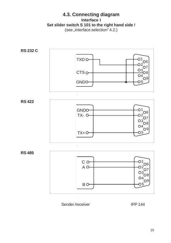
4.3. Connecting diagramInterface I
Set slider switch S 101 to the right hand side !(see „Interface selection“ 4.2.)
RS 232 C
RS 422
RS 485
Sender /receiver IPP 144
1
5
7
4
38
6
9
2TXD
CTS
GND
1
5
7
4
38
6
9
2GNDTX-
TX+
1
5
7
4
38
6
9
2 C A
B
Specifiescharacter size
Command: GS ! n<< Code >>0x1D , 0x21, n(initial value n=0, Value see table)
<< Function >>Specifies character size ( vertical and horizontalmagnification)
<< Details >>This command is ignored if either a vertical or horizontalmagnification is outside the definable range.In the standard mode, the vertical direction refers to thedirection of paper feed, and the horizontal direction thedirection right to the direction of paper feed. If charactersare 90-degree right or left are specified, the relationshipof the vertical and horizontal directions is reversed.If characters with different vertical magnifications arecontained in the same line, they are aligned to thebaseline.
Bit Function Value 0 1
0 vertical magnification
see Table 2 1
4 Horizontal magnification
see Table 1 5
Table 1
Bit7 Bit6 Bit5 Bit4 Magnification 0 0 0 0 1(Std.) 0 0 0 1 2(horizontal) 0 0 1 1 4(horizontal)
Table 2
Bit3 Bit2 Bit1 Bit0 Magnification 0 0 0 0 1(Std.) 0 0 0 1 2(vertical) 0 0 1 1 4(vertical)

16
Set slider switch S 101to the left hand side !(see „Interface selection“ 4.2.)
Sender active ,IPP 144 - 40 Gpassive
Sender passiveIPP 144 - 40 Gactive
„I“ identifies the direction in which the current flows(20 mA).
Current loop
Sender active IPP 144-40G passive
Sender passive IPP 144-40G active
100 Ohm
41
8.3. Details of printer control commands8.3.1. Short view of control commands
Print character commands (Section 8.3.2.)ESC - n Specifies/clears underlineGS ! n Specifies character size
Bitmap image commands (Section 8.3.3.)ESC * m nL nH Specifies column bitmap imageESC A* nL nH Specifies raster bitmap image
Line feed fommands (Section 8.3.4.)ESC 2 Specifies initial line feedESC 3 n Specifies line feed
Barcode commands (Section 8.3.5.)GS H n Selects print position of HRI characterGS h n Sets barcode heightGS w n Sets width of barcodeGS k m / GS k m n Prints barcode
Print position commands (Section 8.3.6.)ESC $ nL nH Specifies absolute position
8.3.2. Print character commands
Specifies /clearsunderline
Command: ESC - n<< Code >>0x1B , 0x2D, n (0≤n≤2 , 48≤n≤49 , initial value n=0)
<< Function >>Specifies or clears an underline
n Function
0, 48 Clears underline 1, 49 Sets a 1-dot wide underline and
specifies an underline

17
Interface II
RS 232 C
RS 485(Option)
1)
transmitter / receiver IPP 144-40 GE
Explanation concerning the signal names underRS 485.The names A, B, C correspond to the EIA 485 - Standard:inactive or logical „1“; A > B
logical „0“: B > AIf an interface does not comply with that standard, theconnections of A and B must be interchanged.
Standard USB chassis socket type Bpin 1 +5Vpin 2 USBDMpin 3 USBDPpin 4 GND
ProfiBus(Option)
USB(Option)
1
5
7
4
38
6
9
2TXD
CTS
GNDRXD
1
5
7
4
38
6
9
2 B
A
C
1
5
7
4
38
6
9
2RxD/TxD-P
DGND
B Line
A Line +5VRxD/TxD-N
GND
VP
Table explanation:1.Column = ASCII / 2. Column = cyrillic / 3. Column = Hexadecimal
Character set: ASCII and cyrillic
40
1 )1 )1 )1 )1 )
18 39
5. Operation5.1. Operating controls
The numbering of the operating controls refers to thediagrams in chapter 3.
This key has two functions:
• LINE FEED:
During operation the key isused for manual paperfeed.
• In the menu program it is used to accept andsave the parameters selected via „Select“.
This key has two functions:
• MENU:When this key is pressed during operationcontinuously operation for more than 3 seconds, theprinter swiches into programming mode. In this modecan devices parameters be modified or printed out.
• Select:
Within the menu program it is used for selecting thedevice parameters.
LINE FEED /ENTER(2)
MENU /SELECT(3)
LED„Alarm“(4)
The ALARM LED has two functions:1. To indicate „end of paper“2. To indicate that the front door is openExamples:1. The front door is closed.If this LED is lit, the printer has run out of paper. Insert anew paper roll; see section 5.2. „Replacing the Paper Roll“.The front press-button switches (LINE FEED & MENUkeys) are deactivated.2. The front door is open.The LED is lit. Printing may continue until the input buffer isempty, and then the data transmission goes to standby.3. The front door is open and the printer has run out ofpaper.The LED lit. The printer stops printing and the front press-button switches are deactivated.After replacing the paper roll the front press-button switchesare active. The ALARM LED remains ON until the front dooris closed. The printer can start working.
The following character set is used:
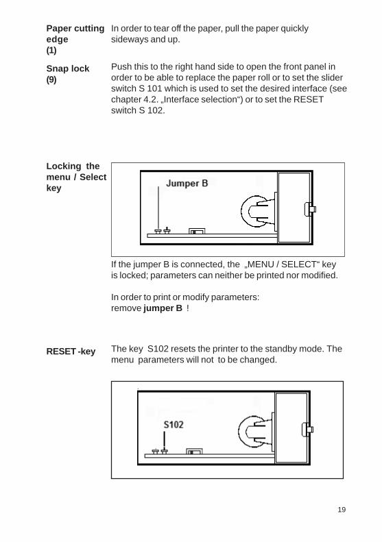
Locking themenu / Selectkey
RESET -key
If the jumper B is connected, the „MENU / SELECT“ keyis locked; parameters can neither be printed nor modified.
In order to print or modify parameters:remove jumper B !
The key S102 resets the printer to the standby mode. Themenu parameters will not to be changed.
19
Paper cuttingedge(1)
Snap lock(9)
In order to tear off the paper, pull the paper quicklysideways and up.
Push this to the right hand side to open the front panel inorder to be able to replace the paper roll or to set the sliderswitch S 101 which is used to set the desired interface (seechapter 4.2. „Interface selection“) or to set the RESETswitch S 102.
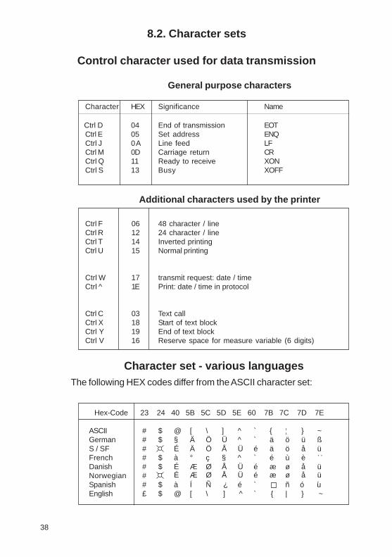
8.2. Character sets
Control character used for data transmission
General purpose characters
Character HEX Significance Name
Ctrl D 04 End of transmission EOTCtrl E 05 Set address ENQCtrl J 0A Line feed LFCtrl M 0D Carriage return CRCtrl Q 11 Ready to receive XONCtrl S 13 Busy XOFF
Additional characters used by the printer
Ctrl F 06 48 character / lineCtrl R 12 24 character / lineCtrl T 14 Inverted printingCtrl U 15 Normal printing
Ctrl W 17 transmit request: date / timeCtrl ̂ 1E Print: date / time in protocol
Ctrl C 03 Text callCtrl X 18 Start of text blockCtrl Y 19 End of text blockCtrl V 16 Reserve space for measure variable (6 digits)
Character set - various languagesThe following HEX codes differ from the ASCII character set:
Hex-Code 23 24 40 5B 5C 5D 5E 60 7B 7C 7D 7E
ASCII # $ @ [ \ ] ^ ` { ¦ } ~German # $ § Ä Ö Ü ^ ` ä ö ü ßS / SF # É Ä Ö Å Ü é ä ö å üFrench # $ à ° ç § ^ ` é ù èDanish # $ É Æ Ø Å Ü é æ ø å üNorwegian #Spanish # $ à Í Ñ é ` ñ ´ ´English $ @ [ \ ` | }
?
:
o u
38
] ^ { ~£
É Æ Ø Å Ü é æ ø å ü
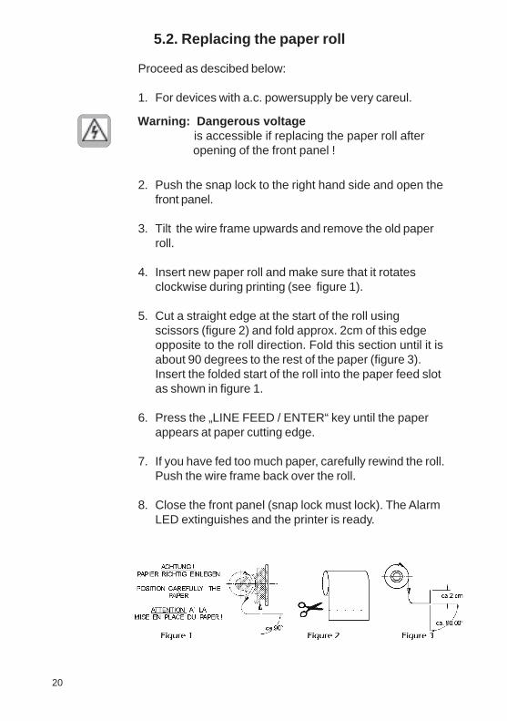
5.2. Replacing the paper roll
Proceed as descibed below:
1. For devices with a.c. powersupply be very careul.
2. Push the snap lock to the right hand side and open thefront panel.
3. Tilt the wire frame upwards and remove the old paperroll.
4. Insert new paper roll and make sure that it rotatesclockwise during printing (see figure 1).
5. Cut a straight edge at the start of the roll usingscissors (figure 2) and fold approx. 2cm of this edgeopposite to the roll direction. Fold this section until it isabout 90 degrees to the rest of the paper (figure 3).Insert the folded start of the roll into the paper feed slotas shown in figure 1.
6. Press the „LINE FEED / ENTER“ key until the paperappears at paper cutting edge.
7. If you have fed too much paper, carefully rewind the roll.Push the wire frame back over the roll.
8. Close the front panel (snap lock must lock). The AlarmLED extinguishes and the printer is ready.
Warning: Dangerous voltage is accessible if replacing the paper roll after opening of the front panel !
20 37
Version E
SET TIME NO ?YES ?
SET TIME 15:57:26_5:57:00 . . . .15:4_:00
>>> 15:48:00TO STORE TIME, PLEASE PRESS „ENTER“TO SET TIME AGAIN, PRESS „SELECT“SET CALENDAR NO ?
YES ?SET CALENDAR 12.01.2003
_2.01.20031_.01.2003. .. .16.02.0_
>>> 16.02.2004CHANGE TIME W<->S NO ?
YES ?CHANGE TIME W<->S 14:07:14W --> S (+1h)S --> W (-1h)>>> 15:07:14
PRINT DATE/TIME NO?YES?
PRINT DATE/TIME CTRL “ ^ “HEADLINE
>>> HEADLINE
SET ACCORDING TO THE BASIC VERSION
SET INTERVALSET MODESET PRINT STRENGTHSET BAUDRATESET DATA FORMATSET PARITYPRINTER ADDRESSSET PRINT FORMATSET CHARACTER/LINESET CHARACTERSET INTERFACE
*** END ***

21
5.3. Menu program
All functions of the IPP 1444 are set via menu programusing the „ENTER“ and „SELECT“ keys and are saved whenthe user quits the program.From then the IPP 144 automatically uses theseparameters.The print format for the printout of the parameters is alwaysNORMAL with 48 character per line, so that the parameterscan be read easily by the user.
Enteringthe menuprogram
Print currentparameters
The various settings are explained in chapter 6.
Press the „MENU / SELECT“ key for approx. 3 seconds .
The IPP 144 reacts by printing
„ACTUAL PARAMETERS ? PRESS „ENTER“
Press the „ENTER“ key.The IPP 144 prints the currently set parameters.
The last line that is printed out says:
„CHANGE PARAMETERS ?“
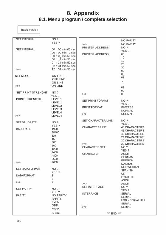
8. Appendix8.1. Menu program / complete selection
Basic version
36
SET INTERVAL NO ?YES ?
SET INTERVAL 00 h 00 min 00 sec00 h 00 min _0 sec00 h 0_ min 50 sec00 h _4 min 50 sec0_ h 34 min 50 sec_2 h 34 min 50 sec
>>> 12 h 34 min 50 sec
SET MODE ON LINE OFF LINE
ON LINE >>> ON LINE
SET PRINT STRENGHT NO ? YES ?
PRINT STRENGTH LEVEL1 LEVEL1 LEVEL2 LEVEL3 LEVEL4
>>> LEVEL4
SET BAUDRATE NO ?YES ?
BAUDRATE 19200384001101503006001200240048009600
>>> 9600
SET DATA FORMAT NO ?YES ?
DATA FORMAT 87
>>> 7
SET PARITY NO ?YES ?
PARITY NO PARITYPARITYEVENODDMARK
SPACE
NO PARITY>>> NO PARITYPRINTER ADDRESS NO ?
YES ?PRINTER ADDRESS 00
_0102030000_01 . .0900
>>> 00
SET PRINT FORMAT NO ?YES ?
PRINT FORMAT INVERSENORMAL
>>> NORMAL
SET CHARACTER/LINE NO ?YES ?
CHARACTER/LINE 48 CHARACTERS48 CHARACTERS40 CHARACTERS24 CHARACTERS20 CHARACTERS
>>> 20 CHARACTERSCHARACTER SET NO ?
YES ?CHARACTER ASCII
GERMANFRENCHDANISHNORWEGIANSPANISHUKCYRILLICASCII
>>> ASCIISET INTERFACE NO ?
YES ?INTERFACE SERIAL
SERIALUSB - SERIAL IF 2SERIAL
>>> SERIAL
*** END ***
22
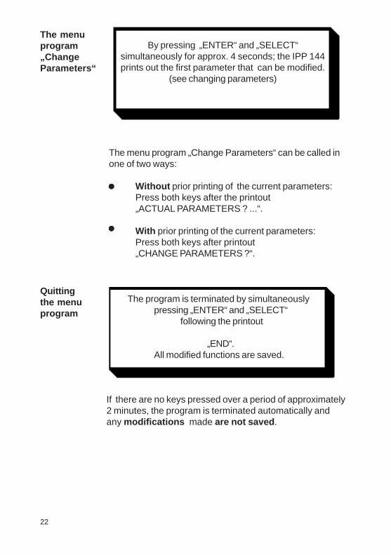
The menuprogram„ChangeParameters“
The menu program „Change Parameters“ can be called inone of two ways:
Without prior printing of the current parameters:Press both keys after the printout„ACTUAL PARAMETERS ? ...“.
With prior printing of the current parameters:Press both keys after printout„CHANGE PARAMETERS ?“.
•••••
•••••
Quittingthe menuprogram
If there are no keys pressed over a period of approximately2 minutes, the program is terminated automatically andany modifications made are not saved .
By pressing „ENTER“ and „SELECT“simultaneously for approx. 4 seconds; the IPP 144prints out the first parameter that can be modified.
(see changing parameters)
The program is terminated by simultaneouslypressing „ENTER“ and „SELECT“
following the printout
„END“.All modified functions are saved.
35
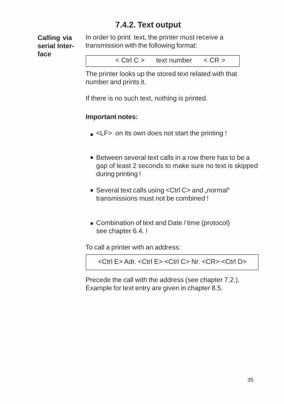
Important notes:
<LF> on its own does not start the printing !
Between several text calls in a row there has to be agap of least 2 seconds to make sure no text is skippedduring printing !
Several text calls using <Ctrl C> and „normal“transmissions must not be combined !
Combination of text and Date / time (protocol)see chapter 6.4. !
To call a printer with an address:
Precede the call with the address (see chapter 7.2.).Example for text entry are given in chapter 8.5.
.
.
.
.
<Ctrl E> Adr. <Ctrl E> <Ctrl C> Nr. <CR> <Ctrl D>
7.4.2. Text output
Calling viaserial Inter-face
In order to print text, the printer must receive atransmission with the following format:
< Ctrl C > text number < CR >
The printer looks up the stored text related with thatnumber and prints it.
If there is no such text, nothing is printed.

23
Changingparameters
Example:
SET BAUDRATE NO ?
„SELECT“ „ENTER“
YES ?
„ENTER“
BAUDRATE 300 300
„SELECT“
600
„ENTER“
>>> 600TO STORE BAUDRATE; PLEASE PRESS „ENTER“SET BAUDRATE AGAIN, PLEASE PRESS „SELECT“
„ENTER“
SET DATA FORMAT NO ?
Explanation In case
1: Baudrate 600 (Baud) 2: Baudrate 300 (Baud) is saved is saved
The IPP 144 prints one of the changeableparameters:
Press „ENTER“ to accept the parameter andto move to the next one.
Press „SELECT“ to display the nextparameter option.
34
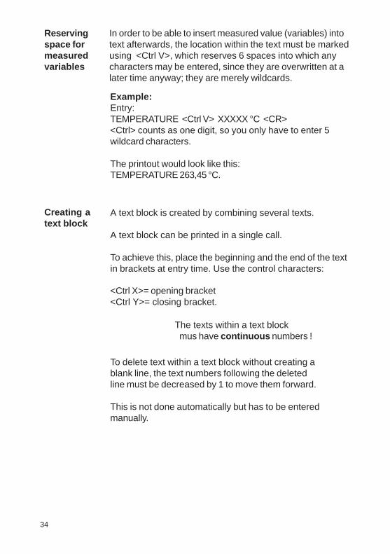
Reservingspace formeasuredvariables
In order to be able to insert measured value (variables) intotext afterwards, the location within the text must be markedusing <Ctrl V>, which reserves 6 spaces into which anycharacters may be entered, since they are overwritten at alater time anyway; they are merely wildcards.
Creating atext block
Example:Entry:TEMPERATURE <Ctrl V> XXXXX °C <CR><Ctrl> counts as one digit, so you only have to enter 5wildcard characters.
The printout would look like this:TEMPERATURE 263,45 °C.
A text block is created by combining several texts.
A text block can be printed in a single call.
To achieve this, place the beginning and the end of the textin brackets at entry time. Use the control characters:
<Ctrl X>= opening bracket<Ctrl Y>= closing bracket.
The texts within a text block mus have continuous numbers !
To delete text within a text block without creating ablank line, the text numbers following the deletedline must be decreased by 1 to move them forward.
This is not done automatically but has to be enteredmanually.
24
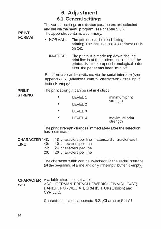
6. Adjustment6.1. General settings
The various settings and device parameters are selectedand set via the menu program (see chapter 5.3.).The appendix contains a summary.
NORMAL: The printout can be read duringprinting.The last line that was printed out ison top.
INVERSE: The printout is made top down, the lastprint line is at the bottom. In this case theprintout is in the proper chronological orderafter the paper has been torn off.
·
·
PRINTFORMAT
CHARACTER /LINE
48: 48 characters per line = standard character width40: 40 characters per line24: 24 characters per line20: 20 characters per line
The character width can be switched via the serial interface(at the beginning of a line and only if the input buffer is empty).
CHARACTERSET
Available character sets are:ASCII, GERMAN, FRENCH, SWEDISH/FINNISH (S/SF),DANISH, NORWEGIAN, SPANISH, UK (English) andCYRILLIC.
Character sets see appendix 8.2. „Character Sets“ !
Print formats can be switched via the serial interface (seeappendix 8.2. „additional control characters“), if the inputbuffer is empty!
The print strength can be set in 4 steps.
• LEVEL 1 minimum printstrength
• LEVEL 2
• LEVEL 3
• LEVEL 4 maximum printstrength
The print strength changes immediately after the selectionhas been made.
PRINTSTRENGT
33
With Handshake, provided RTS (or XON/XOFF protocol) isused to control the data transmitter:Data input:<Ctrl C> 1 <CR> <Ctrl C> 2 <CR> <Ctrl C> 3 <CR>
Actual Print-out:
Machine No. 3 pre-stored Text No. 1Automatic mode pre-stored Text No. 2Status NORMAL pre-stored Text No. 3
7.4. Version E (IPP 144 - 40 GE)7.4.1.Text entry
Text can only be entered via Interface II.
The maximum text length is 40 characters. If the text lengthexceeds 40 characters, only the first 40 characters aresaved.
Text will be input via Windows programming software. Thereis a special task for inputting, adding, overwriting anddeleting texts. The text number must be two-digit.
You must set the following printer parameters:
Baudrate: 9600Data format: 8Parity: NO PARITYInterface: SERIAL
For details of the Input task see the Windows programmingsoftware manual.

25
INTERFACE
PRINTINTERVAL
• SERIAL• USB - Serial IF2 (version E only)
This sets the printer for data transmission via serialinterface or USB-interface.
The printing of measuring values can be carried out underinternal timer control.Setting range: 10 s ... 24 h in steps of 10 s.
The interval starts, when the last received line was printed.
r For more information see chapter 7.3. „HandshakeMessages“ !
BAUDRATE
DATA FORMAT
6.2. Serial interface settings
There are ten baud rates available:
110; 150; 300; 600; 1200; 2400; 4800; 9600;19200 and 38400 Baud.
There are two formats available:
7-bit or 8-bit - transmission,1 start bit / ... / parity / 1 stop bit.
Attention:With 7 bit no parity, the sender must be set to 2 stopbits!
PARITY There are five options available:
Even; Odd; Mark; Space; No parity.There is no check made.
MODE There are 2 operating modes:
• ONLINE: The device is ready to receive.
• OFFLINE: The device is not ready to receive.
32
Improved handshaking for pre-stored textsAfter receiving the control command <CR> the printer nowsets RTS at „BUSY“ or the signal XOFF is transmitted.When the printing of pre-stored text is complete, RTS isreset or the signal XON is transmitted.This handshake can be used to control the datatransmission and prevent rapid text calls being lost oroverwritten.Note:Without Handshake the following can occur, if the textcalls are sent in too quickly:Data input:<Ctrl C> 1 <CR> <Ctrl C> 2 <CR> <Ctrl C> 3 <CR>
Actual Print-out:
Machine No. 3 pre-stored Text No. 12 just „2“ printed, Text No. 2 missing3 just „3“ printed, Text No. 3 missing
XON / XOFF The report functions „Printer read/not ready“ are handledby this protocol if no handshake lines are connected (RS 232 C, RS 422 or RS 485).This function only applies to the E version, Interface II.
XON is transmitted if the IPP 144-40 GE is ready toreceive.
XOFF is transmitted if the IPP 144-40 GE is not readyto receive (see above).
Note:If the IPP 144-40 GE is not ready to receive, it transmitsthis character just once, not continuously.No adjustments have to be made, this protocol alwaysruns parallel to the hardware handshake.
During the preset wait delay the interface is not ready toreceive. After expiry of the wait delay the RTS signal(or XON) becomes active again and requests the subse-quent transmission.The next interval begins upon receiving of <CR> or<CR + LF>. <LF> on its own is not accepted.
Printinterval(serial)

26
Each printer IPP 144 - 40 G / IPP 144 - 40 GE can beaddressed. This allows the tramsmission of data toseveral printers via one data line.
Up to 31 printers may be called from one sender (e.g. aPLC). The respective address is set in the menuprogram.
For more information see chapter 7.2. „Addressing“ !
PRINTERADDRESS
Settingthe time
Date and time are factory set. In order to modifythese values the menu program must be called andthe following message must be displayed:
SET TIME NO ?
.
..
SET TIME 12 : 31 : 33
_2 : 31 : 00
If the time is modified, the seconds are automatically set tozero. Instructions on how to change values,see thedescription of input the date on the next page.
If the time has been entered and „Enter“ has been pressed,the following is displayed:
>>> 22 : 31 : 00
HourMinute
Second
TO STORE TIME; PLEASE PRESS „ENTER“
SET TIME AGAIN; PLEASE PRESS „SELECT“
If time has been entered correctly, press „Enter“. If the timehas been entered incorrectly, repeat the input by pressing„Select“.
6.3. Date / time (only E-version)
31
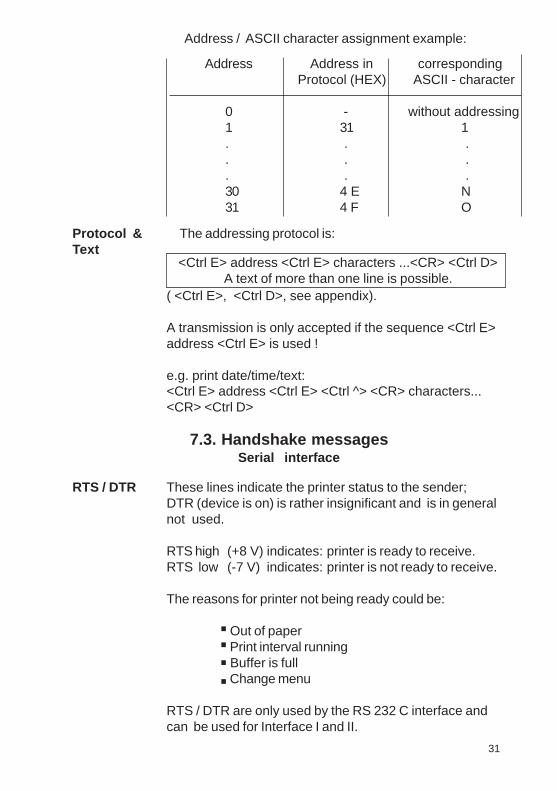
7.3. Handshake messagesSerial interface
These lines indicate the printer status to the sender;DTR (device is on) is rather insignificant and is in generalnot used.
RTS high (+8 V) indicates: printer is ready to receive.RTS low (-7 V) indicates: printer is not ready to receive.
The reasons for printer not being ready could be:
Out of paper Print interval running Buffer is full Change menu
RTS / DTR are only used by the RS 232 C interface andcan be used for Interface I and II.
..
..
RTS / DTR
The addressing protocol is:
<Ctrl E> address <Ctrl E> characters ...<CR> <Ctrl D>A text of more than one line is possible.
( <Ctrl E>, <Ctrl D>, see appendix).
A transmission is only accepted if the sequence <Ctrl E>address <Ctrl E> is used !
e.g. print date/time/text:<Ctrl E> address <Ctrl E> <Ctrl ^> <CR> characters...<CR> <Ctrl D>
Protocol &Text
Address / ASCII character assignment example:
Address Address in corresponding Protocol (HEX) ASCII - character
0 - without addressing1 31 1. . .. . .. . .30 4 E N31 4 F O

27
Finally the currently set date is printed out again.
>>> 24. 03. 2004
Note:
Incorrect entries, e.g. day 33 of a month, will not beaccepted by the printer.Instead, it starts over at the base value 00.
Date entry
SET CALENDAR NO ?
„SELECT“
YES ?
„ENTER“
SET CALENDAR 15. 03.2004
_5. 03.2004
The printed cursor to the left of the 5 indicates thatthis position can be modified; in our example this isthe decade of the day value. The „Select“ key isused to print the possible values successively; inour example this is 0, 1, 2 and 3, To accept thevalue press „Enter“; the cursor jumps to the nextposition to the right ... etc.
The date is set like the time. After the current timehas been printed, the following line appears:
30
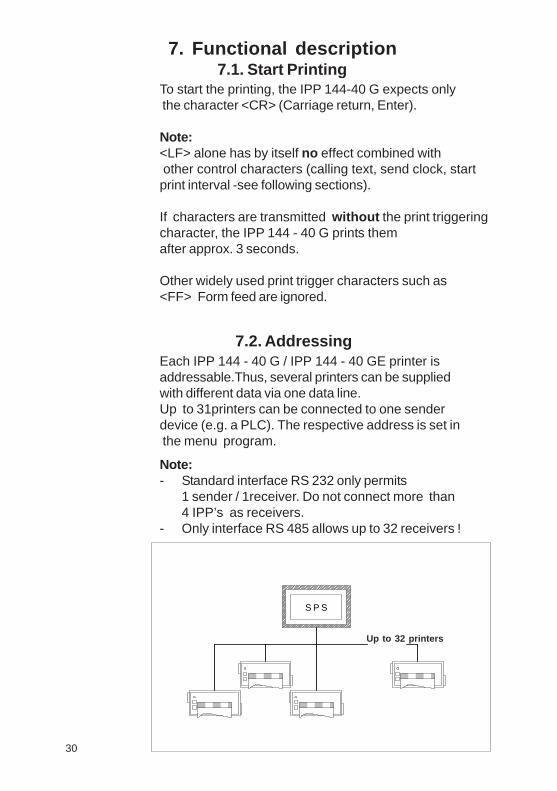
7. Functional description7.1. Start Printing
To start the printing, the IPP 144-40 G expects only the character <CR> (Carriage return, Enter).
Note:<LF> alone has by itself no effect combined with other control characters (calling text, send clock, startprint interval -see following sections).
If characters are transmitted without the print triggeringcharacter, the IPP 144 - 40 G prints themafter approx. 3 seconds.
Other widely used print trigger characters such as<FF> Form feed are ignored.
Note:- Standard interface RS 232 only permits
1 sender / 1receiver. Do not connect more than4 IPP’s as receivers.
- Only interface RS 485 allows up to 32 receivers !
Each IPP 144 - 40 G / IPP 144 - 40 GE printer isaddressable.Thus, several printers can be suppliedwith different data via one data line.Up to 31printers can be connected to one senderdevice (e.g. a PLC). The respective address is set in the menu program.
7.2. Addressing
S P S
Up to 32 printers
28
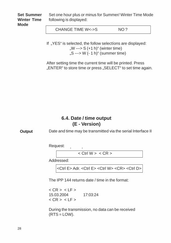
6.4. Date / time output(E - Version)
Output Date and time may be transmitted via the serial Interface II
Request:
Addressed:
The IPP 144 returns date / time in the format:
< CR > < LF >15.03.2004 17:03:24< CR > < LF >
During the transmission, no data can be received(RTS = LOW).
< Ctrl W > < CR >
<Ctrl E> Adr. <Ctrl E> <Ctrl W> <CR> <Ctrl D>
If „YES“ is selected, the follow selectíons are displayed:„W ---> S (+1 h)“ (winter time)„S ---> W (- 1 h)“ (summer time)
After setting time the current time will be printed. Press„ENTER“ to store time or press „SELECT“ to set time again.
Set SummerWinter TimeMode
Set one hour plus or minus for Summer/ Winter Time Modefollowing is displayed:
CHANGE TIME W<->S NO ?
e.g.:15.03.2004 16:57:30Oil temperature 367,5 °COil pressure o.k.Boiler 1
Pause >
15.03.20004 16:58:59Boiler 2 still activeTemperature 258,6 °C
Date and time only precede the transmission if thecharacter <Ctrl ̂ > has been received.
PRINT DATE / TIME CTRL „ ^ „
PRINT DATE / TIME HEADLINE
Serialprotocol
Printdate/time„always“
There are two options available:Each transmission is preceded with the date/time (always).Date and time only precede the transmission if controlcommand has been received.
this optional feature is selected in the menu program under:
For several messages in a row (i.e. the IPP 144 is stillprinting), the date & time is printed once only at thebeginning of the transmission.
The IPP 144 is capable of printing date and time togetherwith measured values or text as a protocol. In this case,date and time precede the printout.
Print date/time with areceivedcontrolcommand
29

28
6.4. Date / time output(E - Version)
Output Date and time may be transmitted via the serial Interface II
Request:
Addressed:
The IPP 144 returns date / time in the format:
< CR > < LF >15.03.2004 17:03:24< CR > < LF >
During the transmission, no data can be received(RTS = LOW).
< Ctrl W > < CR >
<Ctrl E> Adr. <Ctrl E> <Ctrl W> <CR> <Ctrl D>
If „YES“ is selected, the follow selectíons are displayed:„W ---> S (+1 h)“ (winter time)„S ---> W (- 1 h)“ (summer time)
After setting time the current time will be printed. Press„ENTER“ to store time or press „SELECT“ to set time again.
Set SummerWinter TimeMode
Set one hour plus or minus for Summer/ Winter Time Modefollowing is displayed:
CHANGE TIME W<->S NO ?
e.g.:15.03.2004 16:57:30Oil temperature 367,5 °COil pressure o.k.Boiler 1
Pause >
15.03.20004 16:58:59Boiler 2 still activeTemperature 258,6 °C
Date and time only precede the transmission if thecharacter <Ctrl ̂ > has been received.
PRINT DATE / TIME CTRL „ ^ „
PRINT DATE / TIME HEADLINE
Serialprotocol
Printdate/time„always“
There are two options available:Each transmission is preceded with the date/time (always).Date and time only precede the transmission if controlcommand has been received.
this optional feature is selected in the menu program under:
For several messages in a row (i.e. the IPP 144 is stillprinting), the date & time is printed once only at thebeginning of the transmission.
The IPP 144 is capable of printing date and time togetherwith measured values or text as a protocol. In this case,date and time precede the printout.
Print date/time with areceivedcontrolcommand
29
27
Finally the currently set date is printed out again.
>>> 24. 03. 2004
Note:
Incorrect entries, e.g. day 33 of a month, will not beaccepted by the printer.Instead, it starts over at the base value 00.
Date entry
SET CALENDAR NO ?
„SELECT“
YES ?
„ENTER“
SET CALENDAR 15. 03.2004
_5. 03.2004
The printed cursor to the left of the 5 indicates thatthis position can be modified; in our example this isthe decade of the day value. The „Select“ key isused to print the possible values successively; inour example this is 0, 1, 2 and 3, To accept thevalue press „Enter“; the cursor jumps to the nextposition to the right ... etc.
The date is set like the time. After the current timehas been printed, the following line appears:
30
7. Functional description7.1. Start Printing
To start the printing, the IPP 144-40 G expects only the character <CR> (Carriage return, Enter).
Note:<LF> alone has by itself no effect combined with other control characters (calling text, send clock, startprint interval -see following sections).
If characters are transmitted without the print triggeringcharacter, the IPP 144 - 40 G prints themafter approx. 3 seconds.
Other widely used print trigger characters such as<FF> Form feed are ignored.
Note:- Standard interface RS 232 only permits
1 sender / 1receiver. Do not connect more than4 IPP’s as receivers.
- Only interface RS 485 allows up to 32 receivers !
Each IPP 144 - 40 G / IPP 144 - 40 GE printer isaddressable.Thus, several printers can be suppliedwith different data via one data line.Up to 31printers can be connected to one senderdevice (e.g. a PLC). The respective address is set in the menu program.
7.2. Addressing
S P S
Up to 32 printers
26
Each printer IPP 144 - 40 G / IPP 144 - 40 GE can beaddressed. This allows the tramsmission of data toseveral printers via one data line.
Up to 31 printers may be called from one sender (e.g. aPLC). The respective address is set in the menuprogram.
For more information see chapter 7.2. „Addressing“ !
PRINTERADDRESS
Settingthe time
Date and time are factory set. In order to modifythese values the menu program must be called andthe following message must be displayed:
SET TIME NO ?
.
..
SET TIME 12 : 31 : 33
_2 : 31 : 00
If the time is modified, the seconds are automatically set tozero. Instructions on how to change values,see thedescription of input the date on the next page.
If the time has been entered and „Enter“ has been pressed,the following is displayed:
>>> 22 : 31 : 00
HourMinute
Second
TO STORE TIME; PLEASE PRESS „ENTER“
SET TIME AGAIN; PLEASE PRESS „SELECT“
If time has been entered correctly, press „Enter“. If the timehas been entered incorrectly, repeat the input by pressing„Select“.
6.3. Date / time (only E-version)
31
7.3. Handshake messagesSerial interface
These lines indicate the printer status to the sender;DTR (device is on) is rather insignificant and is in generalnot used.
RTS high (+8 V) indicates: printer is ready to receive.RTS low (-7 V) indicates: printer is not ready to receive.
The reasons for printer not being ready could be:
Out of paper Print interval running Buffer is full Change menu
RTS / DTR are only used by the RS 232 C interface andcan be used for Interface I and II.
..
..
RTS / DTR
The addressing protocol is:
<Ctrl E> address <Ctrl E> characters ...<CR> <Ctrl D>A text of more than one line is possible.
( <Ctrl E>, <Ctrl D>, see appendix).
A transmission is only accepted if the sequence <Ctrl E>address <Ctrl E> is used !
e.g. print date/time/text:<Ctrl E> address <Ctrl E> <Ctrl ^> <CR> characters...<CR> <Ctrl D>
Protocol &Text
Address / ASCII character assignment example:
Address Address in corresponding Protocol (HEX) ASCII - character
0 - without addressing1 31 1. . .. . .. . .30 4 E N31 4 F O

25
INTERFACE
PRINTINTERVAL
• SERIAL• USB - Serial IF2 (version E only)
This sets the printer for data transmission via serialinterface or USB-interface.
The printing of measuring values can be carried out underinternal timer control.Setting range: 10 s ... 24 h in steps of 10 s.
The interval starts, when the last received line was printed.
r For more information see chapter 7.3. „HandshakeMessages“ !
BAUDRATE
DATA FORMAT
6.2. Serial interface settings
There are ten baud rates available:
110; 150; 300; 600; 1200; 2400; 4800; 9600;19200 and 38400 Baud.
There are two formats available:
7-bit or 8-bit - transmission,1 start bit / ... / parity / 1 stop bit.
Attention:With 7 bit no parity, the sender must be set to 2 stopbits!
PARITY There are five options available:
Even; Odd; Mark; Space; No parity.There is no check made.
MODE There are 2 operating modes:
• ONLINE: The device is ready to receive.
• OFFLINE: The device is not ready to receive.
32
Improved handshaking for pre-stored textsAfter receiving the control command <CR> the printer nowsets RTS at „BUSY“ or the signal XOFF is transmitted.When the printing of pre-stored text is complete, RTS isreset or the signal XON is transmitted.This handshake can be used to control the datatransmission and prevent rapid text calls being lost oroverwritten.Note:Without Handshake the following can occur, if the textcalls are sent in too quickly:Data input:<Ctrl C> 1 <CR> <Ctrl C> 2 <CR> <Ctrl C> 3 <CR>
Actual Print-out:
Machine No. 3 pre-stored Text No. 12 just „2“ printed, Text No. 2 missing3 just „3“ printed, Text No. 3 missing
XON / XOFF The report functions „Printer read/not ready“ are handledby this protocol if no handshake lines are connected (RS 232 C, RS 422 or RS 485).This function only applies to the E version, Interface II.
XON is transmitted if the IPP 144-40 GE is ready toreceive.
XOFF is transmitted if the IPP 144-40 GE is not readyto receive (see above).
Note:If the IPP 144-40 GE is not ready to receive, it transmitsthis character just once, not continuously.No adjustments have to be made, this protocol alwaysruns parallel to the hardware handshake.
During the preset wait delay the interface is not ready toreceive. After expiry of the wait delay the RTS signal(or XON) becomes active again and requests the subse-quent transmission.The next interval begins upon receiving of <CR> or<CR + LF>. <LF> on its own is not accepted.
Printinterval(serial)

24
6. Adjustment6.1. General settings
The various settings and device parameters are selectedand set via the menu program (see chapter 5.3.).The appendix contains a summary.
NORMAL: The printout can be read duringprinting.The last line that was printed out ison top.
INVERSE: The printout is made top down, the lastprint line is at the bottom. In this case theprintout is in the proper chronological orderafter the paper has been torn off.
·
·
PRINTFORMAT
CHARACTER /LINE
48: 48 characters per line = standard character width40: 40 characters per line24: 24 characters per line20: 20 characters per line
The character width can be switched via the serial interface(at the beginning of a line and only if the input buffer is empty).
CHARACTERSET
Available character sets are:ASCII, GERMAN, FRENCH, SWEDISH/FINNISH (S/SF),DANISH, NORWEGIAN, SPANISH, UK (English) andCYRILLIC.
Character sets see appendix 8.2. „Character Sets“ !
Print formats can be switched via the serial interface (seeappendix 8.2. „additional control characters“), if the inputbuffer is empty!
The print strength can be set in 4 steps.
• LEVEL 1 minimum printstrength
• LEVEL 2
• LEVEL 3
• LEVEL 4 maximum printstrength
The print strength changes immediately after the selectionhas been made.
PRINTSTRENGT
33
With Handshake, provided RTS (or XON/XOFF protocol) isused to control the data transmitter:Data input:<Ctrl C> 1 <CR> <Ctrl C> 2 <CR> <Ctrl C> 3 <CR>
Actual Print-out:
Machine No. 3 pre-stored Text No. 1Automatic mode pre-stored Text No. 2Status NORMAL pre-stored Text No. 3
7.4. Version E (IPP 144 - 40 GE)7.4.1.Text entry
Text can only be entered via Interface II.
The maximum text length is 40 characters. If the text lengthexceeds 40 characters, only the first 40 characters aresaved.
Text will be input via Windows programming software. Thereis a special task for inputting, adding, overwriting anddeleting texts. The text number must be two-digit.
You must set the following printer parameters:
Baudrate: 9600Data format: 8Parity: NO PARITYInterface: SERIAL
For details of the Input task see the Windows programmingsoftware manual.
23
Changingparameters
Example:
SET BAUDRATE NO ?
„SELECT“ „ENTER“
YES ?
„ENTER“
BAUDRATE 300 300
„SELECT“
600
„ENTER“
>>> 600TO STORE BAUDRATE; PLEASE PRESS „ENTER“SET BAUDRATE AGAIN, PLEASE PRESS „SELECT“
„ENTER“
SET DATA FORMAT NO ?
Explanation In case
1: Baudrate 600 (Baud) 2: Baudrate 300 (Baud) is saved is saved
The IPP 144 prints one of the changeableparameters:
Press „ENTER“ to accept the parameter andto move to the next one.
Press „SELECT“ to display the nextparameter option.
34
Reservingspace formeasuredvariables
In order to be able to insert measured value (variables) intotext afterwards, the location within the text must be markedusing <Ctrl V>, which reserves 6 spaces into which anycharacters may be entered, since they are overwritten at alater time anyway; they are merely wildcards.
Creating atext block
Example:Entry:TEMPERATURE <Ctrl V> XXXXX °C <CR><Ctrl> counts as one digit, so you only have to enter 5wildcard characters.
The printout would look like this:TEMPERATURE 263,45 °C.
A text block is created by combining several texts.
A text block can be printed in a single call.
To achieve this, place the beginning and the end of the textin brackets at entry time. Use the control characters:
<Ctrl X>= opening bracket<Ctrl Y>= closing bracket.
The texts within a text block mus have continuous numbers !
To delete text within a text block without creating ablank line, the text numbers following the deletedline must be decreased by 1 to move them forward.
This is not done automatically but has to be enteredmanually.
22
The menuprogram„ChangeParameters“
The menu program „Change Parameters“ can be called inone of two ways:
Without prior printing of the current parameters:Press both keys after the printout„ACTUAL PARAMETERS ? ...“.
With prior printing of the current parameters:Press both keys after printout„CHANGE PARAMETERS ?“.
•••••
•••••
Quittingthe menuprogram
If there are no keys pressed over a period of approximately2 minutes, the program is terminated automatically andany modifications made are not saved .
By pressing „ENTER“ and „SELECT“simultaneously for approx. 4 seconds; the IPP 144prints out the first parameter that can be modified.
(see changing parameters)
The program is terminated by simultaneouslypressing „ENTER“ and „SELECT“
following the printout
„END“.All modified functions are saved.
35
Important notes:
<LF> on its own does not start the printing !
Between several text calls in a row there has to be agap of least 2 seconds to make sure no text is skippedduring printing !
Several text calls using <Ctrl C> and „normal“transmissions must not be combined !
Combination of text and Date / time (protocol)see chapter 6.4. !
To call a printer with an address:
Precede the call with the address (see chapter 7.2.).Example for text entry are given in chapter 8.5.
.
.
.
.
<Ctrl E> Adr. <Ctrl E> <Ctrl C> Nr. <CR> <Ctrl D>
7.4.2. Text output
Calling viaserial Inter-face
In order to print text, the printer must receive atransmission with the following format:
< Ctrl C > text number < CR >
The printer looks up the stored text related with thatnumber and prints it.
If there is no such text, nothing is printed.
21
5.3. Menu program
All functions of the IPP 1444 are set via menu programusing the „ENTER“ and „SELECT“ keys and are saved whenthe user quits the program.From then the IPP 144 automatically uses theseparameters.The print format for the printout of the parameters is alwaysNORMAL with 48 character per line, so that the parameterscan be read easily by the user.
Enteringthe menuprogram
Print currentparameters
The various settings are explained in chapter 6.
Press the „MENU / SELECT“ key for approx. 3 seconds .
The IPP 144 reacts by printing
„ACTUAL PARAMETERS ? PRESS „ENTER“
Press the „ENTER“ key.The IPP 144 prints the currently set parameters.
The last line that is printed out says:
„CHANGE PARAMETERS ?“
8. Appendix8.1. Menu program / complete selection
Basic version
36
SET INTERVAL NO ?YES ?
SET INTERVAL 00 h 00 min 00 sec00 h 00 min _0 sec00 h 0_ min 50 sec00 h _4 min 50 sec0_ h 34 min 50 sec_2 h 34 min 50 sec
>>> 12 h 34 min 50 sec
SET MODE ON LINE OFF LINE
ON LINE >>> ON LINE
SET PRINT STRENGHT NO ? YES ?
PRINT STRENGTH LEVEL1 LEVEL1 LEVEL2 LEVEL3 LEVEL4
>>> LEVEL4
SET BAUDRATE NO ?YES ?
BAUDRATE 19200384001101503006001200240048009600
>>> 9600
SET DATA FORMAT NO ?YES ?
DATA FORMAT 87
>>> 7
SET PARITY NO ?YES ?
PARITY NO PARITYPARITYEVENODDMARK
SPACE
NO PARITY>>> NO PARITYPRINTER ADDRESS NO ?
YES ?PRINTER ADDRESS 00
_0102030000_01 . .0900
>>> 00
SET PRINT FORMAT NO ?YES ?
PRINT FORMAT INVERSENORMAL
>>> NORMAL
SET CHARACTER/LINE NO ?YES ?
CHARACTER/LINE 48 CHARACTERS48 CHARACTERS40 CHARACTERS24 CHARACTERS20 CHARACTERS
>>> 20 CHARACTERSCHARACTER SET NO ?
YES ?CHARACTER ASCII
GERMANFRENCHDANISHNORWEGIANSPANISHUKCYRILLICASCII
>>> ASCIISET INTERFACE NO ?
YES ?INTERFACE SERIAL
SERIALUSB - SERIAL IF 2SERIAL
>>> SERIAL
*** END ***

5.2. Replacing the paper roll
Proceed as descibed below:
1. For devices with a.c. powersupply be very careul.
2. Push the snap lock to the right hand side and open thefront panel.
3. Tilt the wire frame upwards and remove the old paperroll.
4. Insert new paper roll and make sure that it rotatesclockwise during printing (see figure 1).
5. Cut a straight edge at the start of the roll usingscissors (figure 2) and fold approx. 2cm of this edgeopposite to the roll direction. Fold this section until it isabout 90 degrees to the rest of the paper (figure 3).Insert the folded start of the roll into the paper feed slotas shown in figure 1.
6. Press the „LINE FEED / ENTER“ key until the paperappears at paper cutting edge.
7. If you have fed too much paper, carefully rewind the roll.Push the wire frame back over the roll.
8. Close the front panel (snap lock must lock). The AlarmLED extinguishes and the printer is ready.
Warning: Dangerous voltage is accessible if replacing the paper roll after opening of the front panel !
20 37
Version E
SET TIME NO ?YES ?
SET TIME 15:57:26_5:57:00 . . . .15:4_:00
>>> 15:48:00TO STORE TIME, PLEASE PRESS „ENTER“TO SET TIME AGAIN, PRESS „SELECT“SET CALENDAR NO ?
YES ?SET CALENDAR 12.01.2003
_2.01.20031_.01.2003. .. .16.02.0_
>>> 16.02.2004CHANGE TIME W<->S NO ?
YES ?CHANGE TIME W<->S 14:07:14W --> S (+1h)S --> W (-1h)>>> 15:07:14
PRINT DATE/TIME NO?YES?
PRINT DATE/TIME CTRL “ ^ “HEADLINE
>>> HEADLINE
SET ACCORDING TO THE BASIC VERSION
SET INTERVALSET MODESET PRINT STRENGTHSET BAUDRATESET DATA FORMATSET PARITYPRINTER ADDRESSSET PRINT FORMATSET CHARACTER/LINESET CHARACTERSET INTERFACE
*** END ***
Locking themenu / Selectkey
RESET -key
If the jumper B is connected, the „MENU / SELECT“ keyis locked; parameters can neither be printed nor modified.
In order to print or modify parameters:remove jumper B !
The key S102 resets the printer to the standby mode. Themenu parameters will not to be changed.
19
Paper cuttingedge(1)
Snap lock(9)
In order to tear off the paper, pull the paper quicklysideways and up.
Push this to the right hand side to open the front panel inorder to be able to replace the paper roll or to set the sliderswitch S 101 which is used to set the desired interface (seechapter 4.2. „Interface selection“) or to set the RESETswitch S 102.
8.2. Character sets
Control character used for data transmission
General purpose characters
Character HEX Significance Name
Ctrl D 04 End of transmission EOTCtrl E 05 Set address ENQCtrl J 0A Line feed LFCtrl M 0D Carriage return CRCtrl Q 11 Ready to receive XONCtrl S 13 Busy XOFF
Additional characters used by the printer
Ctrl F 06 48 character / lineCtrl R 12 24 character / lineCtrl T 14 Inverted printingCtrl U 15 Normal printing
Ctrl W 17 transmit request: date / timeCtrl ̂ 1E Print: date / time in protocol
Ctrl C 03 Text callCtrl X 18 Start of text blockCtrl Y 19 End of text blockCtrl V 16 Reserve space for measure variable (6 digits)
Character set - various languagesThe following HEX codes differ from the ASCII character set:
Hex-Code 23 24 40 5B 5C 5D 5E 60 7B 7C 7D 7E
ASCII # $ @ [ \ ] ^ ` { ¦ } ~German # $ § Ä Ö Ü ^ ` ä ö ü ßS / SF # É Ä Ö Å Ü é ä ö å üFrench # $ à ° ç § ^ ` é ù èDanish # $ É Æ Ø Å Ü é æ ø å üNorwegian #Spanish # $ à Í Ñ é ` ñ ´ ´English $ @ [ \ ` | }
?
:
o u
38
] ^ { ~£
É Æ Ø Å Ü é æ ø å ü

18 39
5. Operation5.1. Operating controls
The numbering of the operating controls refers to thediagrams in chapter 3.
This key has two functions:
• LINE FEED:
During operation the key isused for manual paperfeed.
• In the menu program it is used to accept andsave the parameters selected via „Select“.
This key has two functions:
• MENU:When this key is pressed during operationcontinuously operation for more than 3 seconds, theprinter swiches into programming mode. In this modecan devices parameters be modified or printed out.
• Select:
Within the menu program it is used for selecting thedevice parameters.
LINE FEED /ENTER(2)
MENU /SELECT(3)
LED„Alarm“(4)
The ALARM LED has two functions:1. To indicate „end of paper“2. To indicate that the front door is openExamples:1. The front door is closed.If this LED is lit, the printer has run out of paper. Insert anew paper roll; see section 5.2. „Replacing the Paper Roll“.The front press-button switches (LINE FEED & MENUkeys) are deactivated.2. The front door is open.The LED is lit. Printing may continue until the input buffer isempty, and then the data transmission goes to standby.3. The front door is open and the printer has run out ofpaper.The LED lit. The printer stops printing and the front press-button switches are deactivated.After replacing the paper roll the front press-button switchesare active. The ALARM LED remains ON until the front dooris closed. The printer can start working.
The following character set is used:

17
Interface II
RS 232 C
RS 485(Option)
1)
transmitter / receiver IPP 144-40 GE
Explanation concerning the signal names underRS 485.The names A, B, C correspond to the EIA 485 - Standard:inactive or logical „1“; A > B
logical „0“: B > AIf an interface does not comply with that standard, theconnections of A and B must be interchanged.
Standard USB chassis socket type Bpin 1 +5Vpin 2 USBDMpin 3 USBDPpin 4 GND
ProfiBus(Option)
USB(Option)
1
5
7
4
38
6
9
2TXD
CTS
GNDRXD
1
5
7
4
38
6
9
2 B
A
C
1
5
7
4
38
6
9
2RxD/TxD-P
DGND
B Line
A Line +5VRxD/TxD-N
GND
VP
Table explanation:1.Column = ASCII / 2. Column = cyrillic / 3. Column = Hexadecimal
Character set: ASCII and cyrillic
40
1 )1 )1 )1 )1 )

16
Set slider switch S 101to the left hand side !(see „Interface selection“ 4.2.)
Sender active ,IPP 144 - 40 Gpassive
Sender passiveIPP 144 - 40 Gactive
„I“ identifies the direction in which the current flows(20 mA).
Current loop
Sender active IPP 144-40G passive
Sender passive IPP 144-40G active
100 Ohm
41
8.3. Details of printer control commands8.3.1. Short view of control commands
Print character commands (Section 8.3.2.)ESC - n Specifies/clears underlineGS ! n Specifies character size
Bitmap image commands (Section 8.3.3.)ESC * m nL nH Specifies column bitmap imageESC A* nL nH Specifies raster bitmap image
Line feed fommands (Section 8.3.4.)ESC 2 Specifies initial line feedESC 3 n Specifies line feed
Barcode commands (Section 8.3.5.)GS H n Selects print position of HRI characterGS h n Sets barcode heightGS w n Sets width of barcodeGS k m / GS k m n Prints barcode
Print position commands (Section 8.3.6.)ESC $ nL nH Specifies absolute position
8.3.2. Print character commands
Specifies /clearsunderline
Command: ESC - n<< Code >>0x1B , 0x2D, n (0≤n≤2 , 48≤n≤49 , initial value n=0)
<< Function >>Specifies or clears an underline
n Function
0, 48 Clears underline 1, 49 Sets a 1-dot wide underline and
specifies an underline

1542
4.3. Connecting diagramInterface I
Set slider switch S 101 to the right hand side !(see „Interface selection“ 4.2.)
RS 232 C
RS 422
RS 485
Sender /receiver IPP 144
1
5
7
4
38
6
9
2TXD
CTS
GND
1
5
7
4
38
6
9
2GNDTX-
TX+
1
5
7
4
38
6
9
2 C A
B
Specifiescharacter size
Command: GS ! n<< Code >>0x1D , 0x21, n(initial value n=0, Value see table)
<< Function >>Specifies character size ( vertical and horizontalmagnification)
<< Details >>This command is ignored if either a vertical or horizontalmagnification is outside the definable range.In the standard mode, the vertical direction refers to thedirection of paper feed, and the horizontal direction thedirection right to the direction of paper feed. If charactersare 90-degree right or left are specified, the relationshipof the vertical and horizontal directions is reversed.If characters with different vertical magnifications arecontained in the same line, they are aligned to thebaseline.
Bit Function Value 0 1
0 vertical magnification
see Table 2 1
4 Horizontal magnification
see Table 1 5
Table 1
Bit7 Bit6 Bit5 Bit4 Magnification 0 0 0 0 1(Std.) 0 0 0 1 2(horizontal) 0 0 1 1 4(horizontal)
Table 2
Bit3 Bit2 Bit1 Bit0 Magnification 0 0 0 0 1(Std.) 0 0 0 1 2(vertical) 0 0 1 1 4(vertical)

14 43
Slide snap lock to the right hand side, swivel front door out.Now you can see the switch S 101 on the printed circuitboard.- For RS 232 C, RS 422 and RS 485 set switch S 101
to the right hand side.- For Current loop, set switch S 101 to the left hand
side.
IMPORTANT:This switching only applies to Interface I.
If the printer is connected to the sender device (e.g. to a PLC) the interface parameters must be matched to those at the sender device. See chapter 6.2. which describes the setting of the baudrate, data format, stop bit and parity bit.
4.2. Interface selection (Interface I)
If the printer is connected to the senderdevice (e.g. to a PLC) the interface para-meters must be matched to those at thesender device. See chapter 6.2. whichdescribes the setting of baudrate, dataformat, stop bit and parity bit.
8.3.3. Bitmap image commandsPrints columnbitmap image
Command: ESC *m nL nH d1 dk<< Code >>
0x1B , 0x2A , m , nL , nH , d1 dkwhere: m=0, 32, 0≤nL≤255 , 0≤nH≤3, 0≤d≤255
<< Function >>Specifies a bitmap image in mode m for the number of dotsspecified by nL and nH.
m Mode No. of No. ofvertical dots Data (K)
0 8-dot single density 8 dots nL+nHx256 1 8-dot double density 8 dots nL+nHx25632 24-dot single density 24 dots (nL+nHx256)x333 24-dot double density 24 dots (nL+nHx256)x3
<< Details >>Processes the data after nL as normal data if m is outsidethe definable range.nL and nH denote the number ofhorizontal dots of the bitmap image to be printed, which is(nL+nHx256).
If bitmap image data exceeding the number of printabledots in a line is entered, the excess data is discarded.d denotes bitmap image data. The bit for the dot to beprinted is „1“ and the bit the dot not to be printed is „0“.Returns to normal data processing after bitmap imageprocessing.Has no effect on print modes (underline, character size)excluding NORMAL.Prints the entered bitmap image magnified three times inthe vertical direction if m=0 or 1 (8-dot mode) is specifiedand two times in the horizontal direction if m=0 or 32(single density mode) is specified.The data format of a bitmap is as follows:

1344
SerialInterface II(only IPP 144 -40 GE)
Pin Signal
1 GND Ground (shield)
2 RXD (+) Receive data
3 n.c.
4 TXD Transmit data
5 RXD (-) Signal ground
6 n.c.
7 DTR (Data Terminal Ready)+8 V: ready to receive-7 V: not ready to receive
8 RTS (Request To Send)+8 V: ready to receive-7 V: not ready to receive
9 n.c.
This interface can either be operated under hardwarehandshake (DTR, RTS) or software handshake(XON / XOFF - Protocol). This does not require specialsettings.
See chapter 4.3.: Connecting diagram
PrintsbarcodePrintsbarcode
Bitmap-Data format
Dot Col.1 Col.2 Col.n 1 MSB : d1 d4 .... d 3n-2 8 9 : d2 d5 .... d 3n-11617 : d3 d6 .... d 3n LSB24
d 3(n+1)-2 d 3(n+2)-2 .... d 6n-2
d 3(n+1)-1 d 3(n+2)-1 .... d 6n-1
d 3(n+1) d 3(n+2) .... d 6n
Command: ESC A* nL nH d1 dk<< Code >>0x1B , 0x41 , 0x2A , nL , nH , d1 dkwhere: 0≤nL≤255 , 0≤nH≤255, 0≤d≤255
Prints rasterbitmap image
<< Details >>This command is effective only if this command is enteredat the start position of a line in the standard mode.d refersto bitmap image data. The bit for the dot to be printed is„1“ and the bit for the dot not to be printed is „0“.Therequired number of image data per line is as followsdepending on the number of heating elements in the head:
dots of heating element 192 dots 288 dots 384 dots 576 dots No. data per line 24 bytes 36 bytes 48 bytes 72 bytes
<< Function >>Specifies the raster bitmap image specified with(nL + nH x 256) lines in the vertical direction.

12 45
SerialInterface I
Pin Signal
1 GND Ground (shield)
2 RXD (+) Receive data
3 +5 V Output +5 V / 20 mA
4 n.c.
5 RXD (-) Signal ground
6 DTR Open collector; active ifDTR is +8 V
7 DTR (Data Terminal Ready)+8 V: ready to receive-7 V: not ready to receive
8 RTS (Request To Send)+8 V: ready to receive-7 V: not ready to receive(text buffer is full)
9 RTS Open Collector; active ifRTS is +8 V
The serial Interface I has been designed to allow theimplementation of all widely used interfaces:RS 232 C; RS 422; RS 485 and Current loop.See chapter 4.3.: Connecting diagram
The required total number of bitmap image data is ((nL + nH x 256) x no. of data per line) bytes.The format of bitmap data for a printer with n heatingelements in the head is as follows:
MSB LSB
d1 d2 d3 ...... d (n/8)
d (n/8)+1 d (n/8)+2 d (n/8)+3 ...... d (2n/8)
d (2n/8)+1 d (2n/8)+2 d (2n/8)+3 ...... d (3n/8)
:: .......
d (nL+nHx256)x(n/8)
Sets initialline feed
8.3.4. Line feed commandsCommand: ESC 2<< Code >>0x1B , 0x32
<< Function >>Sets the amount of the initial line feed per line to 30 dots.
<< Details >>:The amount of the initial line feed can be set separately forthe standard mode.
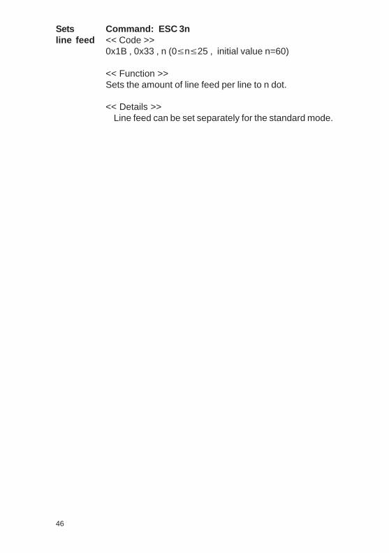
11
Installation
The IPP 144 - 40 G fits into a DIN standard panel cut out. Itis inserted into the switchboard opening from the front sideand is fixed against the switchboard rear using mountingscrews. The switchboard thickness must not exceed 12 mm.
46
4.1. Pin assignments
Pinassignment
4. Connection
Connect the unit as shown in the connection diagramms.Observe all national safety regulations, especially for the power supplyconnections.WARNING: This device must be grounded .
WARNING: This device must be grounded -ACHTUNG: Dieses Gerät muss geerdet werden !
IPP 144 - 40 GOpt.: . . . . . . ..
Alarm
L N1+ -
Serien Nr.:Serial No.:No.de serie
Lithium battery inside ( VERSION E )
CEIPP-AW
10 V...19 V DC; 20 VA
19 V...36 V DC; 18 VA
Interface II
Interface I1
6
RS 232 CRS485Profi BusUSB
1
Sig
GN
D
RX
D (+
)
5
9
RTS
RTS
DT
R
DT
RTX
D
CLA
+5
Vis
GN
D
RX
D (-
)
6
5
9
RTS
DT
R
Sig
GN
D
TXD
RX
D
GN
D
85 V...265 V AC; 45...60Hz ; 15W
EN 61010 -1:2001 CAT III
Setsline feed
Command: ESC 3n<< Code >>0x1B , 0x33 , n (0≤n≤25 , initial value n=60)
<< Function >>Sets the amount of line feed per line to n dot.
<< Details >>Line feed can be set separately for the standard mode.

10
3. Design and installation
Design
1 Paper and cutting edge2 Key: LINE / FEED / Enter3 Key: MENU / Select4 Alarm LED (paper end indicator)5 Serial interface
Interface II (only version E)6 Serial Interface I7 Voltage supply
8 alarm contact(paper end only version E)
9 Snap lock10 Mounting screws11 Protective conductor
connection. Must be connected to ground.12 Connection / paper reroll
mechanism IPP-AW
Make sure that the unit is properlymounted before connection and power on.
47
Front
Rear
8.3.5. Barcode commands
Selectsprintingposition ofHRI character
<< Details >>HRI refers to Human Readable Interpretation.
Command: GS H n<< Code >>0x1D , 0x48 , n (0≤n≤3, initial value n=0)
<< Function >>Selects the print position of HRI characters when printing a barcode.
Setsbarcodeheight
Command: GS h n<< Code >>0x1D , 0x68 , n (1≤n≤255 , initial value n=128)
<< Function >>Sets barcode height to n dots.
Sets widthof barcode
n PRINTING POSITION
0 Not printed (Default)
1 Above bar code
2 Under bar code
3 Above and under bar code
Command: GS w n<< Code >>0 x 1D , 0 x 77 , n ( 2≤n≤6 , initial value n=3)
<< Function >>Specifies barcode width.

2.2. Version E
Type RS 232 C or RS 4851)
ProfiBus or USBBaudrate 110; 150; 300; 600; 1200;
2400; 4800; 9600; 19200; 38400Data format 7 bit2) / 8 bitParity bit even, odd, mark, space, no
separate configurationby Interface II
Type flash memory
Memory size 600 Byte = 15 texts
Type CMOS, battery buffered3)
Accuracy ± 10 ppm = 0,8 sec / day
1) Please specify when ordering; if nothing is specified, RS 232 C issupplied.
2) With 7 bit no parity, the sender must be set to 2 stop bits .3) Lithium battery: 3 V
type: VARTA CR 2/3 AA Typ 6237PANASONIC BR 2/3 A 1 P
This product contains a Lithium battery which must not becut open, incinerated, exposed to temperature above+60 °C or recharged.Dispose of in accordance with national regulations.
^
^
SerialInterface II
Text entry fortexts to bestored
Text memory
Internal clock
Warning !
48 9
n START BYTE BAR CODE TYPE 0 No Start-Byte UPC-A 1 No Start-Byte UPC-E 2 No Start-Byte EAN 13 3 No Start-Byte EAN 8 4 No Start-Byte Code 39 5 No Start-Byte Interleaved 2/5(ITF) 6 No Start-Byte Codabar 7 135 Code 128A 7 136 Code 128B 7 137 Code 128 C
Printsbarcode
Command: GS k n (Start) <data>NUL<< Code >>0x1D , 0x6B , n,(Start)<data> 00H (0≤n≤7)
<< Function >>Selects a barcode system and prints barcodes.
In the case of GS k n:
8.3.6. Print position commands
Specifiesabsoluteposition
Command: ESC $ nL nH<< Code >>0x1B , 0x24, nL , nH (0≤nL≤255 , 0≤nH≤255)
<< Function >>Specifies the next print start position as an absolute positionbased on the left margin position.The next print start position is (nL + nH x 256) dots awayfrom the left margin position.
<< Details >>A print start position specified outside the print area isignored.
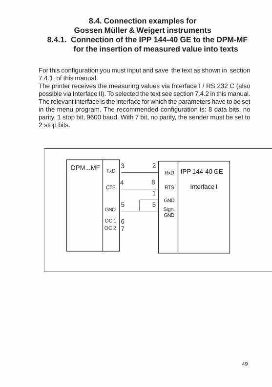
Voltage supply connector Screw type/terminalsWire diameters fixed: 0,2 to 4 mm²
flexible: 0,2 to 2,5 mm²AWG: 24 to 12
Interface I 9 pin D-Sub socket
Interface II 9 pin D-Sub socketorUSB-B socket
Connection for paperreroll mechanism 4pin MASCON, MLAS
Connection forAlarm relay output Screw type/terminal
fixed: 0,2 to 4 mm²flexible: 0,2 to 2,5 mm²AWG: 24 to 12normally open50 V AC, 2 A30 V DC, 2 A
Dimensions(W x H x D) 144 x 72 x 159 mm
Switchboard mounting screws against rear sideof switchboard
Internal fuse( on power supply board) 12V DC : T 3,15 A
24V DC : T 2 A110V - 230V AC : T 2 A
This operating manual applies to software version6.10.12 and higher
49
Connections
Miscellaneous
8
8.4. Connection examples forGossen Müller & Weigert instruments
8.4.1. Connection of the IPP 144-40 GE to the DPM-MFfor the insertion of measured value into texts
For this configuration you must input and save the text as shown in section7.4.1. of this manual.The printer receives the measuring values via Interface I / RS 232 C (alsopossible via Interface II). To selected the text see section 7.4.2 in this manual.The relevant interface is the interface for which the parameters have to be setin the menu program. The recommended configuration is: 8 data bits, noparity, 1 stop bit, 9600 baud. With 7 bit, no parity, the sender must be set to2 stop bits.
DPM...MF IPP 144-40 GETxD
CTS
GND
OC 1OC 2
3
4
6
5
7
2
8
1
5
RxD
RTS
GND
Sign.GND
Interface I
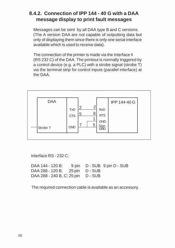
Serial 8 kB
Type RS 232 C; RS 422; RS 485or Current loop
Baudrate 110; 150; 300; 600; 1200;2400; 4800; 9600; 19200;38400
Data format 7 bit1) / 8 bitParity bit even, odd, mark, space, no
Safety acc. to EN 61010-1CAT III > 150 V ≤ 300 Vpollution degree 2
DC 10 V ... 19 V ca. 20 VA2)
19 V ... 36 V ca. 18 VA2)
AC 85 V ... 265 V , 45 - 65 Hz, ca. 15 Wswitch-mode power supply
Temperature ranges:Storage -20 °C to +60 °COperating 0 °C to +45 °CClimate relative humidity < 80 %
up to 31 °C
Protection type acc. to EN 60529/VDE 0470Housing IP 50Terminals IP 00Insulation group C acc. to VDE 0110Mech. strength acc. to IEC 1010EMCEmission EN 55011, Class A
EN55022, Class BSusceptibility EN 61000-4-2 B
EN 61000-4-3 AEN 61000-4-4 B
1) With 7 bit no parity, the sender must be set to 2 stop bits.2) Starting current approx. 3.5 A (10 V ... 19 V) or approx. 1.2 A
(19 V ... 36 V).This value can be used to rate the external fuse.
Input buffer
SerialInterface I
Volt agesupply
Ambientconditions
Standards
50
CE
7
8.4.2. Connection of IPP 144 - 40 G with a DAAmessage display to print fault messages
Messages can be sent by all DAA type B and C versions.(The A version DAA are not capable of outputting data butonly of displaying them since there is only one serial interfaceavailable which is used to receive data).
The connection of the printer is made via the Interface II(RS 232 C) of the DAA. The printout is normally triggered bya control device (e.g. a PLC) with a strobe signal (strobe T)via the terminal strip for control inputs (parallel interface) atthe DAA.
IPP 144-40 GDAA2
57
281
5TxD
CTS
GND
RxD
RTS
GNDSign.GNDStrobe T
Interface RS - 232 C:
DAA 144 - 120 B: 9 pin D - SUB 9 pin D - SUBDAA 288 - 120 B: 25 pin D - SUBDAA 288 - 240 B, C: 25 pin D - SUB
The required connection cable is available as an accessory.
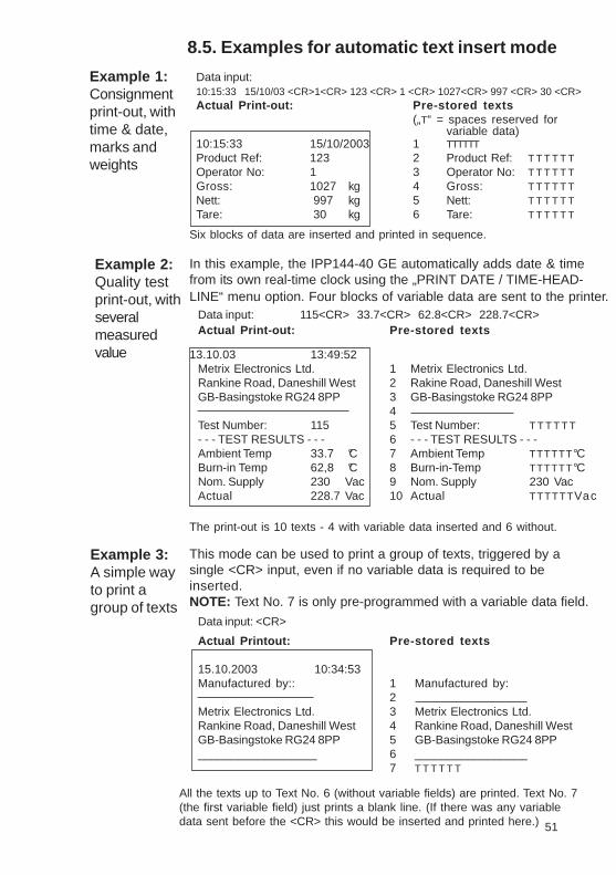
51
2. Technical dat a2.1.Basic version
Printmechanism
Paper
Type of printing Fixed head thermal line
Character representation 576 dots/Line, 8 dots/mm
Print speed approx. 15 line/s (standard text mode)
Character/line 48 characters40 characters24 characters20 characters
Character height 2.5 mm at 48(40) characters 5 mm at 24 (20)characters
Character sets ASC II, german,french, danish, norwegian,swedish / finnish,spanish, english, cyrillic
Service life min. 10x106 Impulse or 50 km
Type commercial grade,document proofthermal paper
Width 80 mm (+0 / -1 mm)
Length approx. 14 m(approx. 4.600 line up to 48 characters per line)
Max. outer roll diameter 40 mm
Min. inner roll diameter 11,5 mm
Temperature standard paper: 0 °C to 60 °C
6
This mode can be used to print a group of texts, triggered by asingle <CR> input, even if no variable data is required to beinserted.NOTE: Text No. 7 is only pre-programmed with a variable data field.
8.5. Examples for automatic text insert mode
Example 1:Consignmentprint-out, withtime & date,marks andweights
Data input:10:15:33 15/10/03 <CR>1<CR> 123 <CR> 1 <CR> 1027<CR> 997 <CR> 30 <CR>Actual Print-out: Pre-stored texts
(„T“ = spaces reserved forvariable data)
10:15:33 15/10/2003 1 TTTTTTProduct Ref: 123 2 Product Ref: T T T T T TOperator No: 1 3 Operator No: T T T T T TGross: 1027 kg 4 Gross: T T T T T TNett: 997 kg 5 Nett: T T T T T TTare: 30 kg 6 Tare: T T T T T T
Six blocks of data are inserted and printed in sequence.
In this example, the IPP144-40 GE automatically adds date & timefrom its own real-time clock using the „PRINT DATE / TIME-HEAD-LINE“ menu option. Four blocks of variable data are sent to the printer.
Data input: 115<CR> 33.7<CR> 62.8<CR> 228.7<CR>Actual Print-out: Pre-stored texts
13.10.03 13:49:52Metrix Electronics Ltd. 1 Metrix Electronics Ltd.Rankine Road, Daneshill West 2 Rakine Road, Daneshill WestGB-Basingstoke RG24 8PP 3 GB-Basingstoke RG24 8PP
4Test Number: 115 5 Test Number: T T T T T T- - - TEST RESULTS - - - 6 - - - TEST RESULTS - - -Ambient Temp 33.7 °C 7 Ambient Temp TTTTTT°CBurn-in Temp 62,8 °C 8 Burn-in-Temp TTTTTT°CNom. Supply 230 Vac 9 Nom. Supply 230 VacActual 228.7 Vac 10 Actual TTTTTTVac
Example 2:Quality testprint-out, withseveralmeasuredvalue
Actual Printout: Pre-stored texts
15.10.2003 10:34:53Manufactured by:: 1 Manufactured by:
2Metrix Electronics Ltd. 3 Metrix Electronics Ltd.Rankine Road, Daneshill West 4 Rankine Road, Daneshill WestGB-Basingstoke RG24 8PP 5 GB-Basingstoke RG24 8PP__________________ 6 _________________
7 T T T T T T
All the texts up to Text No. 6 (without variable fields) are printed. Text No. 7(the first variable field) just prints a blank line. (If there was any variabledata sent before the <CR> this would be inserted and printed here.)
Example 3:A simple wayto print agroup of texts
The print-out is 10 texts - 4 with variable data inserted and 6 without.
Data input: <CR>

The enhanced version IPP 144 - 40 GE provides a second,bi-directional serial interface capable of outputting returnmessages under program control in compliance with a protocol.In addition, this model includes a text memory capable ofstoring up to 15 texts which are called by specifying thecorresponding text number. Moreover, date and time may beprinted with texts and data.It is not possible for the user to upgrade the basic version tothe enhanced version; as this is a different factory version.
EnhancedVersionIPP 144-40 GE
The basic version IPP 144-40 G provides one serial interfacecapable of receiving only. Return (handshake) messages tothe sender are sent via hardware line. Texts and measuringvalues to be printed must be transmitted from the sender devicesince the basic version does not have an internal text memory.It is possible to print with the basic version bitmap image andbarcodes. The bitmap image files and the barcode files aregenerated with printer control commands in a terminal emulationprogram.These files are transmitted by Interface I to the printer.
Basic V ersionIPP 144-40 G
A programming software for use with Microsoft Windows®operating systems has been developed.This software providesfunctions to progam the GE text memory, transfer user definedfonts or symbols and set the printer configuration parameters.Also this software package includes actual Windows® printerdrivers.The software will be shipped on CD-ROM.
MicrosoftWindows ®compatibleprogrammingsoftware
5
II Paper reroll mechanism IPP - AW
1. General information
The IPP-AW is a paper reroll mechanism designed for use with the ThermalGraphics Printer IPP 144-40 G. It has been designed to match the printer incolour and style. It is preferably installed directly underneath the printer. Theprinted paper is automatically wound on a drum by a motor. A front paneldraw allows easy paper handling.
The paper reroll mechanism is a DIN size panel mounting unit. It is suppliedwith power and controlled via connector cable which comes with the unit andwhich is connected to connector 12 of the IPP 144-40 G (see chapter 3.). AnLED indicates the ready status. Depending on the distance beween the twodevices at least the last 9 lines printed remain visible.
52
Print graphicsdirectly fromWindows ®
It is possible to print graphics, such as bmp-, jpg- or tif,directly from Windows® programs.Use a 24-pin type Windows® printer .The following configurations have been verified:Epson Combatible 24-pin andEpson LQ560.

Each printer is addressable, which allows the connection ofup to 31 devices to one sender device via a data line at theRS 485 interface, e.g. to a PLC.
4 53
Review of themodel types
There are two versions of the printer: The basic versionIPP 144-40 G with the Interface I and the enhanced versionIPP 144-40 GE with the Interfaces I and II.There are three option for the voltage supply: 12V DC (10V...19VDC) or 24V DC (19V...36V DC) or 110V/230V AC (switch-modepower supply: 85V...265V AC).InterfaceThere are four options for the Interface II:RS 232 C, RS 485, ProfiBus or USB
The connector for the Interface II of RS 232 C, RS 485 andProfiBus is a 9 pin D-Sub-socket. It is possible to change thisInterface card in the factory. The interface option USB has aspecial USB-B-socket. It is not possible to change thisinterface card with the other cards. Special adapter cablesand converters are used in this situation.
Model Supply V olt age Interface I Interface II
IPP 144-40 GIPP 144-40 GE 232IPP 144-40 GE 485IPP 144-40 GE PBIPP 144-40 GE USB
12V DC 24V DC 110/230V AC12V DC 24V DC 110/230V AC12V DC 24V DC 110/230V AC12V DC 24V DC 110/230V AC12V DC 24V DC 110/230V AC
Yes NoneYes RS 232 CYes RS 485Yes ProfiBusYes USB
Front Rear
1 Status indicator 2 Opening for paper feed3 Handle 4 Connector for connection5 Mounting screws cable IPP 144-40;6 Protective conductor connection (pin connections: Motor
(must be connected to ground) control, +5V, open, GND)7 Brightness LED
The paper reroll mechanism is inserted into the DIN sizepanel cutout from the front side and is clamped against therear of the switchboard using the mounting screws. Theswitchboard thickness must not exceed 12 mm.
Make sure that the unit is properly mountedbefore connection and power on.
Design
Installation
S P S
77777
Up to 32 printers
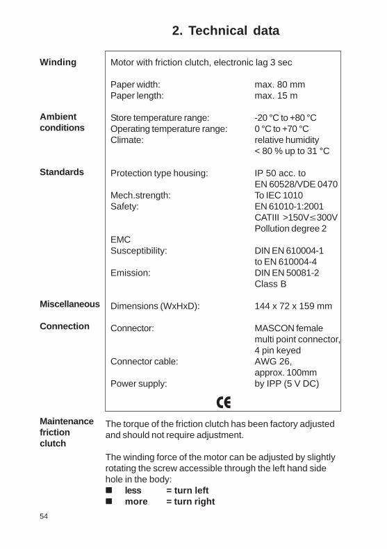
I. IPP 144 - 40 G / IPP 144 - 40 GE
1. General features
The Thermal Graphics Printer IPP 144-40 G (Industrial ProcessPrinter) is a device designed for outputting text, data andgraphics, i.e. measured value, machine and process states, errormessages, production data, etc.
Two application examples:
If connected to a digital voltmeter, the IPP 144-40 G recordsthe measuring values (with date/time for the E version).
Its integrated interface allow the use of the IPP 144-40 G asa peripheral for all PLCs (RS 232 C; RS 422; RS 485; USB;Profibus DP).
The Thermal Graphics Printer is a DIN size panel mounting unitwhich is able to print line widths of up to 48 characters per line.The 14m paper roll (commercial grade document proof thermalpaper) is located inside the housing and can be easily replacedby means of a swivel type front panel. Án end of paper indicatorlights up if the printer runs out of paper.
3
.
.
2. Technical dat a
Motor with friction clutch, electronic lag 3 sec
Paper width: max. 80 mmPaper length: max. 15 m
Store temperature range: -20 °C to +80 °COperating temperature range: 0 °C to +70 °CClimate: relative humidity
< 80 % up to 31 °C
Protection type housing: IP 50 acc. toEN 60528/VDE 0470
Mech.strength: To IEC 1010Safety: EN 61010-1:2001
CATIII >150V≤300VPollution degree 2
EMCSusceptibility: DIN EN 610004-1
to EN 610004-4Emission: DIN EN 50081-2
Class B
Dimensions (WxHxD): 144 x 72 x 159 mm
Connector: MASCON femalemulti point connector,4 pin keyed
Connector cable: AWG 26,approx. 100mm
Power supply: by IPP (5 V DC)
CE
The torque of the friction clutch has been factory adjustedand should not require adjustment.
The winding force of the motor can be adjusted by slightlyrotating the screw accessible through the left hand sidehole in the body:nnnnn less = turn leftnnnnn more = turn right
54
Winding
Ambientconditions
Standards
Miscellaneous
Connection
Maintenancefrictionclutch
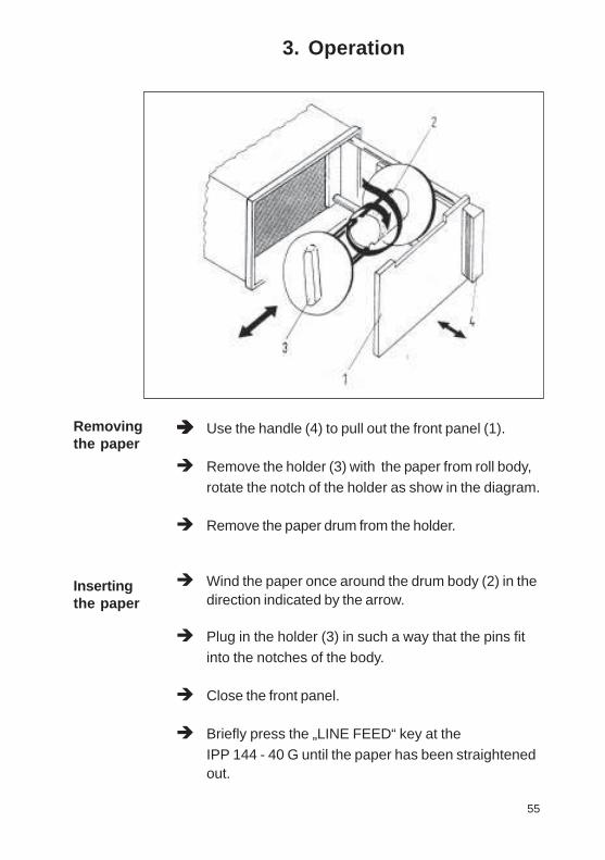
Index
page
Accessories 56Addressing 26, 30Addressing & protocol / text 31Basic version 5Baudrate 25Barcode Commands 47Bitmap image Commands 43Character set 24, 38Connection diagrams 11Connection Examples 59Control characters 38Data format - serial 25Date / time - output via Interface II 28Date / time - setting 26End of paper indication 18Environmental conditions 7Enhanced version (E - version) 5Handshake serial - RTS / DTR 31Handshake serial - XON / XOFF 32Headline data & time 29Input buffer 7Installation 10Interface selection 14Key LINE FEED / ENTER 18Key lock 19Key MENU / SELECT 18KEY RESET 19Line Feed Commands 45Line width (characters per line) 24Mechanical data 8Menu program - complete selection 36Menu program - entry 21Menu program - quitting 22Model types 4
page
Operating controls, general 18Paper 6Paper reroll mechanism 57Parameters, changing 22, 23Parameters, printing the current 21Parity 25Pin assignment current loop 16Pin assignment - Interface I 15Pin assignment - Interface II 17Print character commands 41Print control commands 40Print format 24Print interval - serial 32Print interval - setting 24Print mechanism 6Protocol - serial 29Replacing the paper roll 20Snap lock 18Software version 8Start printing 30Technical data 6Text adding, overwrite 33Text call with measured data, serial 34Text - deleting 33Text entry 33Text entry - block 34Text entry - wildcards 28Text output 35Voltage supply 7Wildcards for measure value 34Windows programming software 5Write protection 19
2
3. Operation
èèèèè Use the handle (4) to pull out the front panel (1).
è Remove the holder (3) with the paper from roll body,rotate the notch of the holder as show in the diagram.
è Remove the paper drum from the holder.
è Wind the paper once around the drum body (2) in thedirection indicated by the arrow.
è Plug in the holder (3) in such a way that the pins fitinto the notches of the body.
è Close the front panel.
è Briefly press the „LINE FEED“ key at theIPP 144 - 40 G until the paper has been straightenedout.
Removingthe paper
Insertingthe paper
55

Table of Content s
page
I. IPP 144 - 40 G / IPP 144 - 40 GE 3 - 56
1. General features 3 - 5
2. Technical dat a 6 - 9
2.1. Basic Version 6 - 82.2. Version E 9
3. Design and installation 10 - 11
4. Connection 11 - 174.1. Pin assignment 11 - 134.2. Interface selection 144.3. Connecting diagram serial 15 - 17
5. Operation 18 - 235.1. Operating controls 18 - 195.2. Replacing the paper roll 205.3. Menu program 21 - 23
6. Adjustments 24 - 296.1. General settings 24 - 256.2. Serial interfaces settings 25 - 266.3. Date / time 26 - 286.4. Date / time Output 28 - 29
7. Functional description 30 - 357.1. Start printing 307.2. Addressing 30 - 317.3. Handshakes messages 31 - 337.4. Version E (IPP 144-40 GE) 33 - 357.4.1. Texts Entry 33 - 347.4.2. Texts output 35
page
8. Appendix 36 - 568.1. Menu program -
complete Selection 36 - 378.2. Character sets 38 - 408.3. Details of printer control 41 - 48
Commands8.3.1. Short view of control
commands 418.3.2. Print character commands 41 - 428.3.3. Bitmap image commands 43 - 458.3.4. Line feed commands 45 - 468.3.5. Barcode commands 47 - 488.3.6. Print position commands 488.4. Connection examples
for GMW instruments 49 - 508.4.1. Connection with DPM / MF 498.4.2. Coupling with DAA 508.5. Examples for automatic
text insert Mode 51
II.Paper RerollMechanism IPP - AW 52 - 551.General information 52 - 53
Design / Installation 532.Technical data 543.Operation 55
III. Accessories 56
1
III Accessories
♦♦♦♦♦ Paper reroll mechanism IPP - AW(incl. connection cable).
♦ Protection cover for use of IPP 144-40 G with IPP-AW,Protection class: IP 64.Dimensions: 155 x 155 [mm].Material: Plexiglas and
Santoprene 101-80 rubber
♦ Connection cable for serial data transmissionto the following devices:
IBM-PC XT and AT or compatiblesSiemens PG 685 (V 24)Siemens PG 675 / 685 (printer interface)Siemens GP270 /TP270/MP370 TOUCH(RS232C)(printer interface)Message displays:DAA 144-120B / 288-120B / 288-240B, Cothers on request.
Connection cable for USB-interface:USB-A connector - USB-B connector
♦ Windows programming software for IPP 144-40 GE version (CD-R)
56

Safety instructions (EN 61010-1)In order to preclude any danger to the operator , the following instructionsshould be followed:a) In case any damage or malfunction is detected, take the unit out of operation without delay.
b) Before disassembling the unit, disconnect all inputs / outputs and the supply voltage. Whenmounting the unit and the connections, make sure all live components are protected frombeing touched directly.
c) Comply with the usual regulations and safety provisions for low and high current systems, inparticular country-specific safety provisions (e.g. VDE 0100).
d) The maximum admissible potential existing between the pin groups as well as to the externalprotective conductor must not be exceeded. Refer to the unit´s identification label.
e) When connecting the unit to other devices (e.g. PCs), the connection must be carefullyplanned. Internal connections in external units (e.g. GND connected to protective earth) maycause excessive voltage potential.
f ) This device must be grounded! For low voltage 12VDC
and 24VDC
systems use screened cable.
Units with a.c. supply voltage must be connected the protective conductor.
g) Make sure that the unit is property mounted before connection and power on !
In order to preclude any damage to the unit, the following items must betaken into account:
The maximum admissible potential between the pin groups must not be exceeded.This applies in particular to high voltage tests.
Refer to the instruction manual !
Warning: Hazardous live volt age !
WARNING:There is always hazardous voltage present in certain parts during the operation of electrical equipment.Non-observance of the safety instructions can result in severe personal injury or damage to property. Only qualified personnel shouldwork on this equipment. The successful and safe operation of this equipment is dependant on proper transport, storage, set-up,installation and careful operation and maintenance.QUALIFIED PERSONNELAre personnel who are familiar with the set-up, installation, commissioning and operation of the product and have the qualificationscorresponding to their activities, e.g.:- Are trained and authorised to energise, de-energise, clear, ground and tag circuits and equipment / systems in accordance with established safety standards.- Are trained in the proper care and use of protective equipment in accordance with established safety practices.- Are trained in first aid.
Safety according to EN 61010-1, VDE 041 1CAT III > 150 V ≤ 300 VPollution degree : 2; indoor use; altitude <2000 m; relative humidity <80 % up to 31 °C;Temperature: 5 °C to 40 °C;
61
Note:

Safety instructions (EN 61010-1)In order to preclude any danger to the operator , the following instructionsshould be followed:a) In case any damage or malfunction is detected, take the unit out of operation without delay.
b) Before disassembling the unit, disconnect all inputs / outputs and the supply voltage. Whenmounting the unit and the connections, make sure all live components are protected frombeing touched directly.
c) Comply with the usual regulations and safety provisions for low and high current systems, inparticular country-specific safety provisions (e.g. VDE 0100).
d) The maximum admissible potential existing between the pin groups as well as to the externalprotective conductor must not be exceeded. Refer to the unit´s identification label.
e) When connecting the unit to other devices (e.g. PCs), the connection must be carefullyplanned. Internal connections in external units (e.g. GND connected to protective earth) maycause excessive voltage potential.
f ) This device must be grounded! For low voltage 12VDC
and 24VDC
systems use screened cable.
Units with a.c. supply voltage must be connected the protective conductor.
g) Make sure that the unit is property mounted before connection and power on !
In order to preclude any damage to the unit, the following items must betaken into account:
The maximum admissible potential between the pin groups must not be exceeded.This applies in particular to high voltage tests.
Refer to the instruction manual !
Warning: Hazardous live volt age !
WARNING:There is always hazardous voltage present in certain parts during the operation of electrical equipment.Non-observance of the safety instructions can result in severe personal injury or damage to property. Only qualified personnel shouldwork on this equipment. The successful and safe operation of this equipment is dependant on proper transport, storage, set-up,installation and careful operation and maintenance.QUALIFIED PERSONNELAre personnel who are familiar with the set-up, installation, commissioning and operation of the product and have the qualificationscorresponding to their activities, e.g.:- Are trained and authorised to energise, de-energise, clear, ground and tag circuits and equipment / systems in accordance with established safety standards.- Are trained in the proper care and use of protective equipment in accordance with established safety practices.- Are trained in first aid.
Safety according to EN 61010-1, VDE 041 1CAT III > 150 V ≤ 300 VPollution degree : 2; indoor use; altitude <2000 m; relative humidity <80 % up to 31 °C;Temperature: 5 °C to 40 °C;
Note:

Thermal Graphics PrintersIPP 144 - 40 G
IPP 144 - 40 GE
Paper Reroll MechanismIPP - AWWe reserve the right to make alterations! Metrix r0.14.10.13 Sach-Nr. 27866 88172
USER`S MANUALVersion 6.10.12 or higher
Exclusive agent for UK & Ireland:
Metrix Electronics Limited Electronic Instrument Solutions for Industry Minchens Court, Minchens Lane, Bramley,
Hampshire RG26 5BH, U.K.Tel. +44 (0)845 03 43 234Fax: +44 (0)845 03 43 233
E-mail:[email protected] Web:www.metrix-electronics.com
GOSSEN Müller & WeigertZN der General Elektronik GmbH
Kleinreuther Weg 88D-90408 Nürnberg
Tel.: +49(0)911/3502-0 Fax: +49(0)911/3502-307E-mail: [email protected] Internet: www.g-mw.de


