42
USER'S MANUAL NX FREQUENCY CONVERTERS FOR SMOOTH CONTROL PROFIBUS DP OPTION BOARD

U S E R ' S M A N U A L
N XF R E Q U E N C Y C O N V E R T E R S
F O R S M O O T H C O N T R O L
P R O F I B U S D PO P T I O N B O A R D

INDEX
1. GENERAL................................................................................................3
2. PROFIBUS DP OPTION BOARD TECHNICAL DATA.....................................4
2.1 General ..........................................................................................................42.2 Profibus cable..................................................................................................5
3. PROFIBUS DP .........................................................................................7
3.1 Introduction .....................................................................................................73.2 Profiles............................................................................................................8
3.2.1 Variable Speed Drive Profile (3.071)............................................................8
4. PROFIBUS FIELDBUS BOARD LAYOUT AND CONNECTIONS ......................9
4.1 Profibus NXOPTC3 option board .......................................................................94.1.1 Grounding of bus cable shield in NXOPTC3 ...............................................10
4.2 Profibus NXOPTC5 option board .....................................................................154.3 Bus terminal resistors ......................................................................................164.4 LED indications ..............................................................................................16
5. INSTALLATION OF VACON NX PROFIBUS BOARD .................................18
6. COMMISSIONING.................................................................................20
6.1 Fieldbus board parameters ..............................................................................206.2 Start-up test....................................................................................................22
7. PROFIBUS-VACON NX INTERFACE.........................................................23
7.1 General ........................................................................................................237.2 Operation mode ............................................................................................237.3 PPO types .....................................................................................................247.4 Process data..................................................................................................25
7.4.1 Control word...........................................................................................277.4.2 Status word.............................................................................................297.4.3 State machine .........................................................................................307.4.4 Reference 1 ............................................................................................317.4.5 Actual value 1.........................................................................................317.4.6 PD1…PD8 ..............................................................................................31
7.5 Parameter data ..............................................................................................337.5.1 Parameter field ........................................................................................34
7.6 Example messages .........................................................................................36
8. FAULT TRACKING..................................................................................38
9. Type files .............................................................................................39
9.1 GSD-file (“Profibus Support Disk” files: vac29500.GSD, vac29500.GSE)..............39
vacon NX Profibus DP 3(42)
1. GENERAL
Vacon NX frequency converters can be connected to the Profibus DP using a fieldbus board.The converter can then be controlled, monitored and programmed from the Host system.
The Profibus fieldbus board shall be installed in slot E on the control board of the frequencyconverter.
WARNING!
Internal components and circuit boards are at high potential when the fre-quency converter is connected to the power source. This voltage is extremelydangerous and may cause death or severe injury if you come into contactwith it.

4(42) NX Profibus DP vacon
Vacon Oyj Tel. +358-201-2121 Fax: +358-201-2121 20524-hour service: +358-40-8371 150 Email: [email protected]
2. PROFIBUS DP OPTION BOARD TECHNICAL DATA
2.1 General
Interface NXOPTC3: Pluggable connector (5.08mm)NXOPTC5: 9-pin DSUB connector (female)
Data transfermethod
RS-485, half-duplex
Transfer cable Twisted pair (1 pair and shield)
Profibus DP con-nections
Electrical isolation 500 VDCProfibus DP As described in document “Profibus Profile for vari-
able speed drives, Profidrive”PPO types 1, 2, 3, 4, 5Baud rate 9.6 kbaud to 12 Mbaud
Communications
Addresses 2 to 126Ambient operatingtemperature
–10°C…55°C
Storing temperature –40°C…60°CHumidity <95%, no condensation allowedAltitude Max. 1000 m
Environment
Vibration 0.5 G at 9…200 HzSafety Fulfils EN50178 standard
Table 2-1. Profibus technical data
vacon NX Profibus DP 5(42)
Vacon Oyj Tel. +358-201-2121 Fax: +358-201-2121 20524-hour service: +358-40-8371 150 Email: [email protected]
2.2 Profibus cable
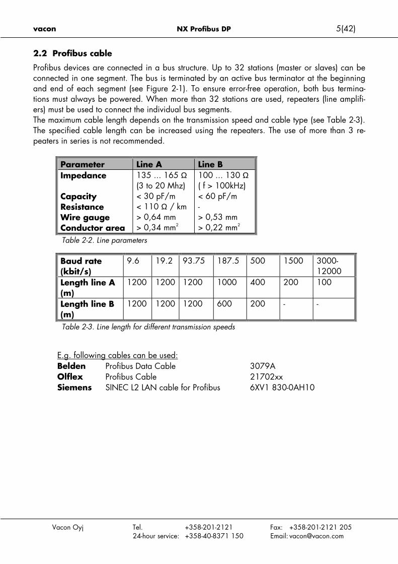
Profibus devices are connected in a bus structure. Up to 32 stations (master or slaves) can beconnected in one segment. The bus is terminated by an active bus terminator at the beginningand end of each segment (see Figure 2-1). To ensure error-free operation, both bus termina-tions must always be powered. When more than 32 stations are used, repeaters (line amplifi-ers) must be used to connect the individual bus segments.The maximum cable length depends on the transmission speed and cable type (see Table 2-3).The specified cable length can be increased using the repeaters. The use of more than 3 re-peaters in series is not recommended.
Parameter Line A Line BImpedance
CapacityResistanceWire gaugeConductor area
135 ... 165 Ω(3 to 20 Mhz)< 30 pF/m< 110 Ω / km> 0,64 mm> 0,34 mm2
100 ... 130 Ω( f > 100kHz)< 60 pF/m-> 0,53 mm> 0,22 mm2
Table 2-2. Line parameters
Baud rate(kbit/s)
9.6 19.2 93.75 187.5 500 1500 3000-12000
Length line A(m)
1200 1200 1200 1000 400 200 100
Length line B(m)
1200 1200 1200 600 200 - -
Table 2-3. Line length for different transmission speeds
E.g. following cables can be used:Belden Profibus Data Cable 3079AOlflex Profibus Cable 21702xxSiemens SINEC L2 LAN cable for Profibus 6XV1 830-0AH10
6(42) NX Profibus DP vacon
Vacon Oyj Tel. +358-201-2121 Fax: +358-201-2121 20524-hour service: +358-40-8371 150 Email: [email protected]
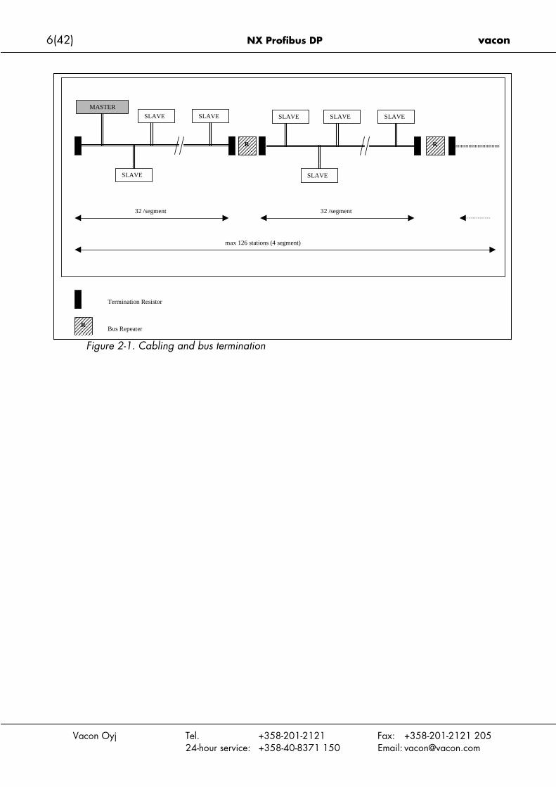
Figure 2-1. Cabling and bus termination
32 /segment
MASTER
SLAVESLAVE
SLAVE
R
SLAVESLAVE
SLAVE
SLAVE
max 126 stations (4 segment)
32 /segment
Termination Resistor
Bus Repeater
R
R

vacon NX Profibus DP 7(42)
Vacon Oyj Tel. +358-201-2121 Fax: +358-201-2121 20524-hour service: +358-40-8371 150 Email: [email protected]
3. PROFIBUS DP
3.1 Introduction
Profibus is a vendor-independent, open fieldbus standard for a wide range of applications inmanufacturing, process and building automation. Vendor independence and openness areguaranteed by the Profibus standard EN 50 170. With Profibus, devices of different manufac-turers can communicate without special interface adjustments. Profibus can be used for bothhigh-speed time critical data transmission and extensive complex communication tasks. The Pro-fibus family consists of three compatible versions.
Profibus DPOptimized for high speed and inexpensive hookup, this Profibus version is designed especiallyfor communication between automation control systems and distributed I/O at the device level.Profibus-DP can be used to replace parallel signal transmission with 24 V or 0 to 20 mA.
Profibus PA
Profibus PA is designed especially for process automation. It permits sensors and actuators tobe connected on one common bus line even in intrinsically-safe areas. Profibus PA permits datacommunication and power over the bus using a 2-wire technology according to the interna-tional standard IEC 1158-2.
Profibus FMS
Profibus FMS is the general-purpose solution for communication tasks at the cell level. PowerfulFMS services open up a wide range of applications and provide great flexibility. Profibus FMScan also be used for extensive and complex communication tasks.
Profibus specifies the technical and functional characteristics of a serial fieldbus system withwhich decentralized digital controllers can be networked together from the field level to the celllevel. Profibus distinguishes between master devices and slave devices.
Master devices determine the data communication on the bus. A master can send messageswithout an external request when it holds the bus access rights (the token). Masters are alsocalled 'active stations' in the Profibus protocol.
Slave devices are peripheral devices. Typical slave devices include input/output devices,valves, drives and measuring transmitters. They do not have bus access rights and they canonly acknowledge received messages or send messages to the master when requested to doso. Slaves are also called 'passive stations'.

8(42) NX Profibus DP vacon
Vacon Oyj Tel. +358-201-2121 Fax: +358-201-2121 20524-hour service: +358-40-8371 150 Email: [email protected]
3.2 Profiles
The Profibus DP protocol defines how user data are to be transmitted between the stations overthe bus. User data are not evaluated by the Profibus DP transmission protocol. The meaning isspecified in the profiles. In addition, the profiles specify how Profibus DP is to be used in theapplication area. The following Profibus DP profile is used in VACON NX Profibus Fieldbusboard.
3.2.1 Variable Speed Drive Profile (3.071)
Leading manufacturers of drive technology have jointly defined the PROFIDRIVE profile. Theprofile specifies how the drives are to be parameterized and how the setpoints and actual val-ues are to be transmitted. This enables drives from different vendors to be exchanged. The pro-file contains necessary specifications for speed control and positioning. It specifies the basicdrive functions while leaving sufficient freedom for application-specific expansions and furtherdevelopments. The profile describes the mapping of the application functions for DP or FMS.

vacon NX Profibus DP 9(42)
Vacon Oyj Tel. +358-201-2121 Fax: +358-201-2121 20524-hour service: +358-40-8371 150 Email: [email protected]
4. PROFIBUS FIELDBUS BOARD LAYOUT AND CONNECTIONS
Vacon Profibus Fieldbus Board is connected to the fieldbus through either a 5-pin pluggablebus connector (board NXOPTC3) or a 9-pin female sub-D-connector (board NXOPTC5).The communication with the control board takes place through the standard Vacon InterfaceBoard Connector.
4.1 Profibus NXOPTC3 option board
Figure 4-1. Vacon Profibus option board NXOPTC3
Signal Connector DescriptionShield 1 Cable shieldVP 2 Supply voltage – plus (5V)RxD/TxD –P 3 Receive/Transmit data – plus (B)RxD/TxD –N 4 Receive/Transmit data – minus (A)DGND 5 Data ground (reference potential for VP)Table 4-1. NXOPTC3 bus connector signals
12345
X6
X1
Bus connector Jumpers Interface board connector

10(42) NX Profibus DP vacon
Vacon
4.1.1 Grounding of bus cable shield in NXOPTC3
The bus cable shield can be grounded in three different ways:a) directly to the frequency converter frameb) to the frame of the frequency converter through an RC filterc) clamping the cable to the converter frame (recommended)
Note: Normally, the option board has already been installed in slot E of the control board. Itis not necessary to detach the whole board for the grounding of the bus cable shield. Just de-tach the terminal block.
4.1.1.1 Grounding the bus cable shield directly to the frequency converter frame usingjumper X1
1 Set jumper X1 in ON position:
Figure 4-2. Jumper X1 positions
2 Strip about 5 cm of the Profibus cable as shown in the picture.Note: Do the same for both bus cables (except for the last device). However, sincethe grounding shall be done on one cable only cut off the exposed part of the othergrounding cable.
F
ON
OFFX1
Oyj Tel. +358-201-2121 Fax: +358-201-2121 20524-hour service: +358-40-8371 150 Email: [email protected]
igure 4-3.

vacon NX Profibus DP 11(42)
Vacon
3 Leave no more than 1 cm of the red and green data cable outside the terminal blockand strip the data cables at about 0.5 cm to fit in the terminals. See pictures below.Note: Do this for both bus cabels.
Figure 4-4.
Oyj Tel. +358-201-2121 Fax: +358-201-2121 20524-hour service: +358-40-8371 150 Email: [email protected]
Figure 4-5.
12(42) NX Profibus DP vacon
Vacon
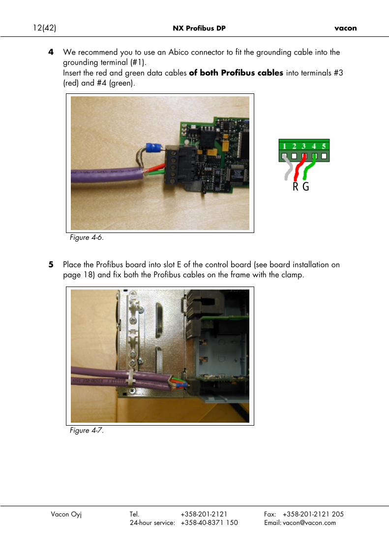
4 We recommend you to use an Abico connector to fit the grounding cable into thegrounding terminal (#1).Insert the red and green data cables of both Profibus cables into terminals #3(red) and #4 (green).
Figure 4-6.
5 Place the Profibus board into slot E of the control board (see board installation onpage 18) and fix both the Profibus cables on the frame with the clamp.
R G
Oyj Tel. +358-201-2121 Fax: +358-201-2121 20524-hour service: +358-40-8371 150 Email: [email protected]
Figure 4-7.

vacon NX Profibus DP 13(42)
4.1.1.2 Grounding the bus cable shield directly to the frequency converter frame using an RC-filter
We recommend you to do the grounding in this manner when the distance between the de-vices exceeds 50 meters (55 yds.). When the distance between the devices is long distur-bances (e.g. voltage spikes) are more likely to appear. In this grounding method, the distur-bances are filtered out. Even if the ground planes of A, B and C are different (which is verytypical e.g. in construction) there is no current between them because the points do not have aground connection.
A B C
Vacon Oyj Tel. +358-201-2121 Fax: +358-201-2121 20524-hour service: +358-40-8371 150 Email: [email protected]
Figure 4-8. Grounding with RC filter
1 Set jumper X1 in OFF position
Figure 4-9. Jumper X1 positions
2 Carry out the grounding in the same way as advised in Chapter 4.1.1.1.
ON
OFFX1
Profibus cable Profibus cable Profibus cable

14(42) NX Profibus DP vacon
4.1.1.3 Grounding by clamping the cable to the converter frame
This manner of grounding is the most effective and especially recommended when the dis-tances between the devices are relatively short (see 4.1.1.2).In this manner of grounding, the position of jumper X1 is of no importance.
Profibus cable Profibus cable Profibus cable
Vacon Oyj Tel. +358-201-2121 Fax: +358-201-2121 20524-hour service: +358-40-8371 150 Email: [email protected]
Figure 4-10. Grounding by clamping the cable to the converter frame
1 Strip about 5 cm of the Profibus cable in the same way as shown in Figure 4-3 but cutoff the grey cable shield.Remember to do this for both bus cables (except for the last device).
2 Leave no more than 1 cm of the red and green data cable outside the terminal blockand strip the data cables at about 0.5 cm to fit in the terminals. See Figure 4-4 andFigure 4-5.Note: Do this for both bus cabels.
3 Insert the red and green data cables of both Profibus cables into terminals #3(red) and #4 (green). See Figure 4-6.
4 Strip the Profibus cable at such a distance from the terminal that you can fix it to theframe with the grounding clamp. See Figure 4-11.
Figure 4-11a. Figure 4-11b.
vacon NX Profibus DP 15(42)
Vacon Oyj Tel. +358-201-2121 Fax: +358-201-2121 20524-hour service: +358-40-8371 150 Email: [email protected]
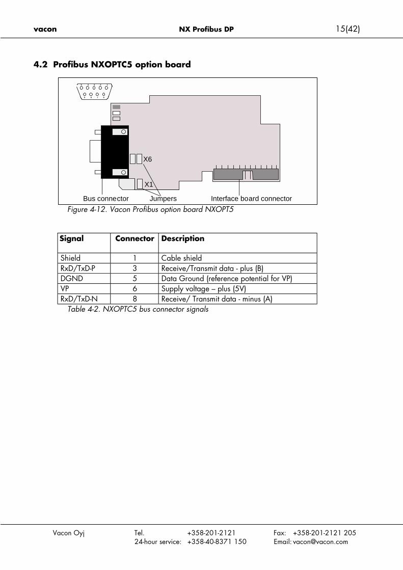
4.2 Profibus NXOPTC5 option board
Figure 4-12. Vacon Profibus option board NXOPT5
Signal Connector Description
Shield 1 Cable shieldRxD/TxD-P 3 Receive/Transmit data - plus (B)DGND 5 Data Ground (reference potential for VP)VP 6 Supply voltage – plus (5V)RxD/TxD-N 8 Receive/ Transmit data - minus (A)
Table 4-2. NXOPTC5 bus connector signals
X6
X1
Bus connector Jumpers Interface board connector
12345
9 8 7 6
16(42) NX Profibus DP vacon
Vacon Oyj Tel. +358-201-2121 Fax: +358-201-2121 20524-hour service: +358-40-8371 150 Email: [email protected]
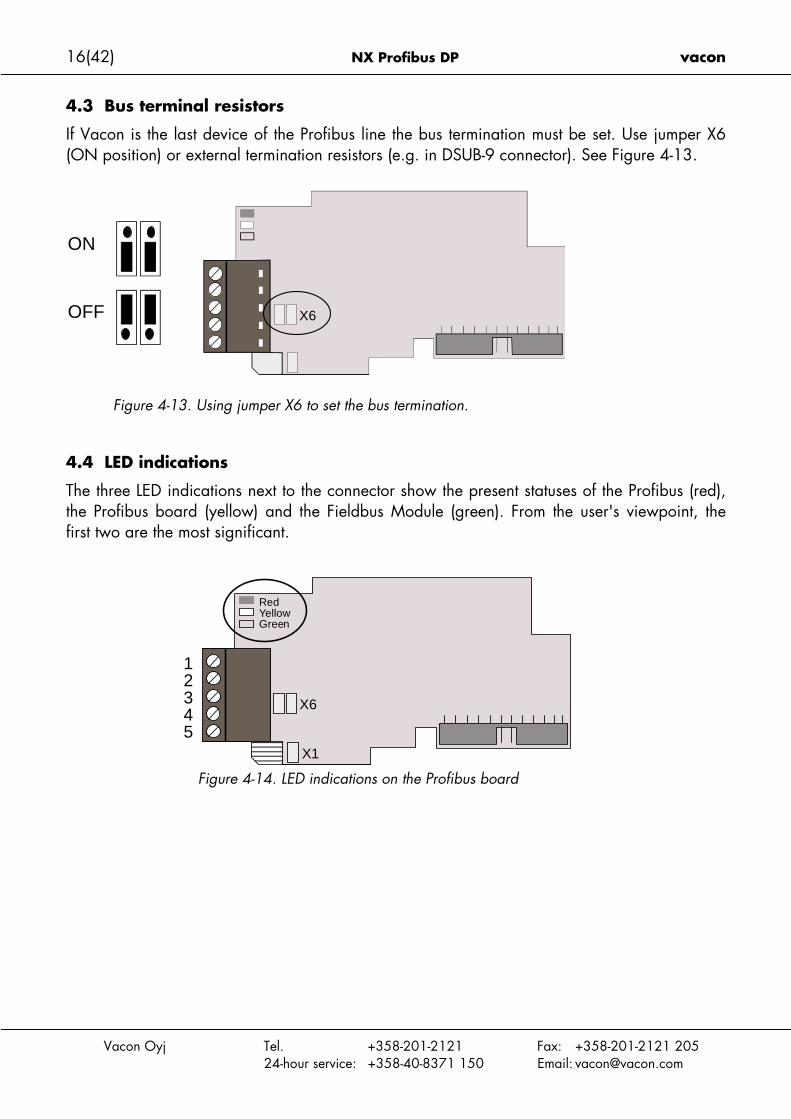
4.3 Bus terminal resistors
If Vacon is the last device of the Profibus line the bus termination must be set. Use jumper X6(ON position) or external termination resistors (e.g. in DSUB-9 connector). See Figure 4-13.
Figure 4-13. Using jumper X6 to set the bus termination.
4.4 LED indications
The three LED indications next to the connector show the present statuses of the Profibus (red),the Profibus board (yellow) and the Fieldbus Module (green). From the user's viewpoint, thefirst two are the most significant.
Figure 4-14. LED indications on the Profibus board
X6
ON
OFF
X6
X1
12345
RedYellowGreen
vacon NX Profibus DP 17(42)
Vacon Oyj Tel. +358-201-2121 Fax: +358-201-2121 20524-hour service: +358-40-8371 150 Email: [email protected]
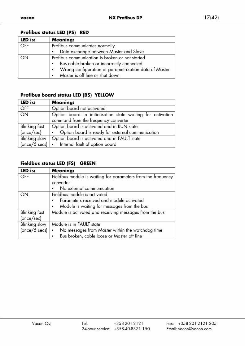
Profibus status LED (PS) REDLED is: Meaning:OFF Profibus communicates normally.
• Data exchange between Master and SlaveON Profibus communication is broken or not started.
• Bus cable broken or incorrectly connected• Wrong configuration or parametrization data of Master• Master is off line or shut down
Profibus board status LED (BS) YELLOW
LED is: Meaning:OFF Option board not activatedON Option board in initialisation state waiting for activation
command from the frequency converterBlinking fast(once/sec)
Option board is activated and in RUN state• Option board is ready for external communication
Blinking slow(once/5 secs)
Option board is activated and in FAULT state• Internal fault of option board
Fieldbus status LED (FS) GREENLED is: Meaning:OFF Fieldbus module is waiting for parameters from the frequency
converter• No external communication
ON Fieldbus module is activated• Parameters received and module activated• Module is waiting for messages from the bus
Blinking fast(once/sec)
Module is activated and receiving messages from the bus
Blinking slow(once/5 secs)
Module is in FAULT state• No messages from Master within the watchdog time• Bus broken, cable loose or Master off line
18(42) NX Profibus DP vacon
Vacon Oyj Tel. +358-201-2121 Fax: +358-201-2121 20524-hour service: +358-40-8371 150 Email: [email protected]
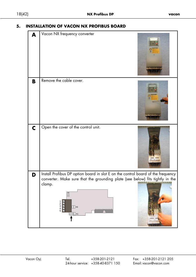
5. INSTALLATION OF VACON NX PROFIBUS BOARD
A Vacon NX frequency converter
B Remove the cable cover.
C Open the cover of the control unit.
D Install Profibus DP option board in slot E on the control board of the frequencyconverter. Make sure that the grounding plate (see below) fits tightly in theclamp.
X6
X1
12345

vacon NX Profibus DP 19(42)
Vacon Oyj Tel. +358-201-2121 Fax: +358-201-2121 20524-hour service: +358-40-8371 150 Email: [email protected]
E Make a sufficiently wide opening for your cable by cutting the grid as wideas necessary.
F Close the cover of the control unit and the cable cover.

20(42) NX Profibus DP vacon
Vacon Oyj Tel. +358-201-2121 Fax: +358-201-2121 20524-hour service: +358-40-8371 150 Email: [email protected]
6. COMMISSIONING
READ FIRST CHAPTER 8 'COMMISSIONING' IN VACON NX USER'S MANUAL (Documentnr. ud00701, please visit http://www.vacon.com/support/documents.html).
6.1 Fieldbus board parameters
The Vacon Profibus board is commissioned with the control keypad by giving values to appro-priate parameters in menu M7 (for locating the expander board menu see Vacon NX User'sManual, Chapter 7).
Expander board menu (M7)The Expander board menu makes it possible for the user 1) to see what expander boards are connectedto the control board and 2) to reach and edit the parameters associated with the expander board.Enter the following menu level (G#) with the Menu button right. At this level, you can browse throughslots A to E with the Browser buttons to see what expander boards are connected. On the lowermostline of the display you also see the number of parameter groups associated with the board.If you still press the Menu button right once you will reach the parameter group level where there aretwo groups: Editable parameters and Monitored values. A further press on the Menu button right takesyou to either of these groups.
Profibus parametersTo commission the Profibus board, enter the level G7.5.1.# from the Parameters group (G7.5.1). Givedesired values to all Profibus parameters (see Figure 6-1 and Table 6-1).
Figure 6-1. Changing the Profibus board commissioning parameter values
Expander BoardG1!G5
READY
I/Oterm
NXOPTC5
READY
I/Oterm
G1!G2
Slave address
READY
I/Oterm
126 enter
CHANGE VALUE
CONFIRM CHANGE
Parameters
READY
I/Oterm
P1!P4
Slave address
READY
I/Oterm
126

vacon NX Profibus DP 21(42)
Vacon Oyj Tel. +358-201-2121 Fax: +358-201-2121 20524-hour service: +358-40-8371 150 Email: [email protected]
# Name Default Range Description1 SLAVE ADDRESS 126 2…1262 BAUD RATE 10 (=AUTO) 1 - 9.6 kBaud
2 - 19.2 kBaud3 - 93.75 kBaud4 - 187.5 kBaud5 - 500 kBaud6 - 1.5 Mbaud7 - 3 MBaud8 - 6 Mbaud9 - 12 Mbaud10 – AUTOMATIC
Communication speed in baud
3 PPO TYPE 1 - PPO12 - PPO23 - PPO34 - PPO45 - PPO5
Parameter, CW/SW, Ref/ActParameter, CW/SW, Ref/Act, PD1-PD4CW/SW, Ref/ActCW/SW, Ref/Act, PD1-PD4Parameter, CW/SW, Ref/Act, PD1-PD8
4 OPERATE MODE 1 – PROFIDRIVE2 – BYPASS3 – ECHO
Use mode ”PROFIDRIVE” with standardapplications
Table 6-1. Profibus parameters
The parameters of every device must be set before connecting to the bus. Especially the pa-rameters “SLAVE ADDRESS” and “PPO TYPE” must be the same as in the master configuration.
Profibus status
To see the present status of the Profibus fieldbus, enter the Profibus status page from Monitormenu (G7.5.2). See Figure 6-2 and Table 6-2 below.
Figure 6-2. Profibus status
Profibus status0 Waiting parameter from Master1 Waiting configuration from Master2 Communication established
Table 6-2. Profibus status indications
Monitor
READY
I/Oterm
V1!V1Profibus status
READY
I/Oterm
2516.0
Message counter
Profibus status

22(42) NX Profibus DP vacon
Vacon Oyj Tel. +358-201-2121 Fax: +358-201-2121 20524-hour service: +358-40-8371 150 Email: [email protected]
6.2 Start-up test
Frequency converter application
Choose Fieldbus (Bus/Comm) as the active control place (see Vacon NX User's Manual, Chap-ter 7.3.3).
Master software
1. Set Control Word value to 0hex.
2. Set Control Word value to 47Fhex.
3. Frequency converter status is RUN
4. Set Reference value to 5000 (=50,00%).
5. The Actual value is 5000 and the frequency converter output frequency is 25,00 Hz
6. Set Control Word value to 7Dhex.
7. Frequency converter status is STOP
If Status Word bit 3 = 1 Status of frequency converter is FAULT.

vacon NX Profibus DP 23(42)
Vacon Oyj Tel. +358-201-2121 Fax: +358-201-2121 20524-hour service: +358-40-8371 150 Email: [email protected]
7. PROFIBUS-VACON NX INTERFACE
Features of the Profibus-Vacon NX interface:• Direct control of Vacon NX ( e.g. Run, Stop, Direction, Speed reference, Fault reset)• Full access to all Vacon NX parameters• Monitor Vacon NX status (e.g. Output frequency, Output current, Fault code)
7.1 General
Data transfer between Profibus DP master and slave takes place via the input/output data field.The Master writes to Slave’s output data and the Slave answers by sending the contents of itsinput data to the Master. The contents of the input/output data is defined in the device profile.The device profile for frequency converters is PROFIDRIVE.The Vacon NX frequency converter can be controlled by Profibus DP Master using the PPO-types defined in Profidrive (see Chapter 7.3). When fieldbus has been selected as the fre-quency converter’s active control place, the frequency converter’s operation can be controlledfrom the Profibus DP Master. Whether or not the active control place is fieldbus, the frequencyconverter can be monitored and its parameters set by the Profibus DP Master.
Figure 7-1. Data transfer between Profibus Master and Slaves
7.2 Operation mode
The parameter Operation mode (G7.5.1.4, see above) defines how the input/output data ishandled on the option board.
PROFIDRIVE• Data transfer follows the document Profibus Profile for variable speed drives, PROFIDRIVE.
BYPASS• The information of the Process Data field is transferred to the application interface without
handling• Parameter setting takes place according to the Profidrive definition
ECHO• The OUTPUT data written by the Master is echoed back to the Master in the INPUT field• The data is not shown in the frequency converter but the echoing is carried out on the op-
tion board• This mode can be used when the function of the bus connection is tested
ProfibusMaster
ProfibusSlave
Protocol Trailer Protocol Header
Protocol Header Protocol Trailer
OUTPUT Data
INPUT Data

24(42) NX Profibus DP vacon
Vacon Oyj Tel. +358-201-2121 Fax: +358-201-2121 20524-hour service: +358-40-8371 150 Email: [email protected]
7.3 PPO types
PPOs (Parameter/Process Data Object) are the communication objects in PROFIBUS DP.
The PPOs in Vacon NX:
Parameter Field Process Data Field
ID IND VALUE CW
SW
REF
ACT
PD1
PD1
PD2
PD2
PD3
PD3
PD4
PD4
PD5
PD5
PD6
PD6
PD7
PD7
PD8
PD8
PPO 1
PPO 2
PPO 3
PPO 4
PPO 5
Descriptions:
Byte
ID Parameter type and number
IND Parameter subindex
VALUE Parameter value
CW Control Word
SW Status Word
REF Reference Value 1
ACT Actual Value 1
PD Process Data
vacon NX Profibus DP 25(42)
Vacon Oyj Tel. +358-201-2121 Fax: +358-201-2121 20524-hour service: +358-40-8371 150 Email: [email protected]
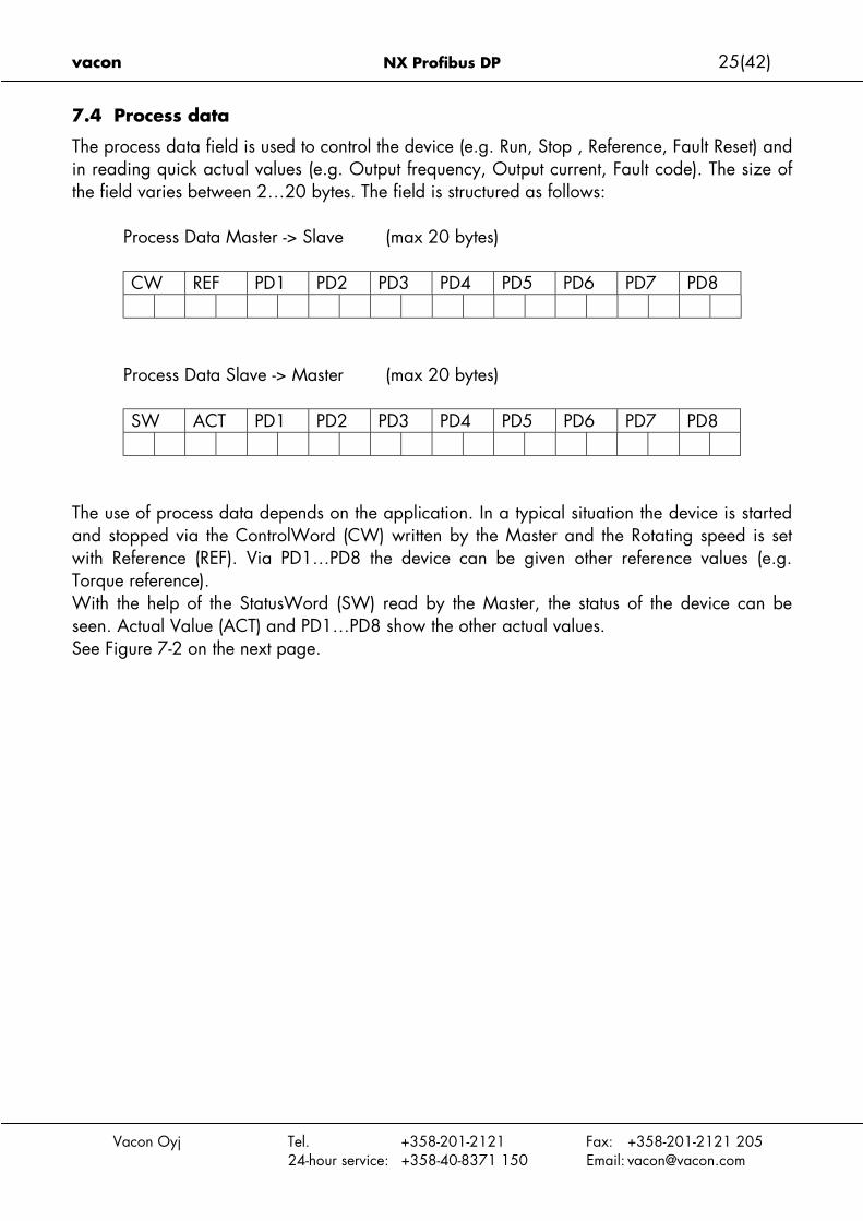
7.4 Process data
The process data field is used to control the device (e.g. Run, Stop , Reference, Fault Reset) andin reading quick actual values (e.g. Output frequency, Output current, Fault code). The size ofthe field varies between 2…20 bytes. The field is structured as follows:
Process Data Master -> Slave (max 20 bytes)
CW REF PD1 PD2 PD3 PD4 PD5 PD6 PD7 PD8
Process Data Slave -> Master (max 20 bytes)
SW ACT PD1 PD2 PD3 PD4 PD5 PD6 PD7 PD8
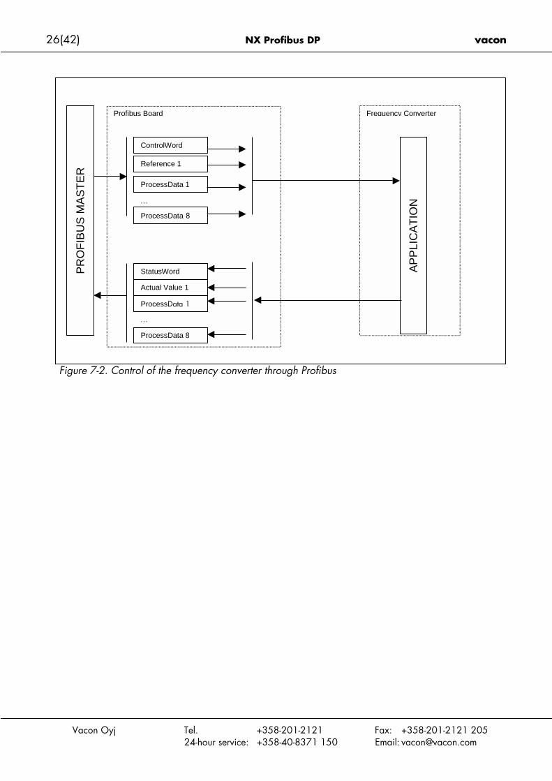
The use of process data depends on the application. In a typical situation the device is startedand stopped via the ControlWord (CW) written by the Master and the Rotating speed is setwith Reference (REF). Via PD1…PD8 the device can be given other reference values (e.g.Torque reference).With the help of the StatusWord (SW) read by the Master, the status of the device can beseen. Actual Value (ACT) and PD1…PD8 show the other actual values.See Figure 7-2 on the next page.
26(42) NX Profibus DP vacon
Vacon Oyj Tel. +358-201-2121 Fax: +358-201-2121 20524-hour service: +358-40-8371 150 Email: [email protected]
Figure 7-2. Control of the frequency converter through Profibus
Frequency ConverterProfibus Board
ControlWord
PR
OF
IBU
S M
AS
TE
R
Reference 1
ProcessData 1
ProcessData 8
…
StatusWord
Actual Value 1
ProcessData 1
ProcessData 8
…
AP
PLI
CA
TIO
N

vacon NX Profibus DP 27(42)
Vacon Oyj Tel. +358-201-2121 Fax: +358-201-2121 20524-hour service: +358-40-8371 150 Email: [email protected]
7.4.1 Control wordCW REF PD1 PD2 PD3 PD4 PD5 PD6 PD7 PD8
The Control command for the state machine (see Figure 7-2). The state machine describes thedevice status and the possible control sequence of the frequency converter. The control word is composed of 16 bits that have the following meanings:
Bit DescriptionValue = 0 Value = 1
0 STOP 1 (by ramp) ON 11 STOP 2 (by coast) ON 22 STOP 3 (by ramp) ON 33 RUN DISABLE ENABLE4 No Action START5 No Action START6 No Action START7 No Action FAULT RESET (0 -> 1)8 No Action No Action9 No Action No Action10 Disable Profibus control Enable Profibus control11 Fieldbus DIN1=OFF Fieldbus DIN1=ON12 Fieldbus DIN2=OFF Fieldbus DIN2=ON13 Fieldbus DIN3=OFF Fieldbus DIN3=ON14 Fieldbus DIN4=OFF Fieldbus DIN4=ON15 Fieldbus DIN5=OFF Fieldbus DIN5=ON
Table 7-1. Control word bit descriptions
With the help of the control word, start and stop commands can be given to the device. Also afault can be acknowledged.
28(42) NX Profibus DP vacon
Vacon Oyj Tel. +358-201-2121 Fax: +358-201-2121 20524-hour service: +358-40-8371 150 Email: [email protected]
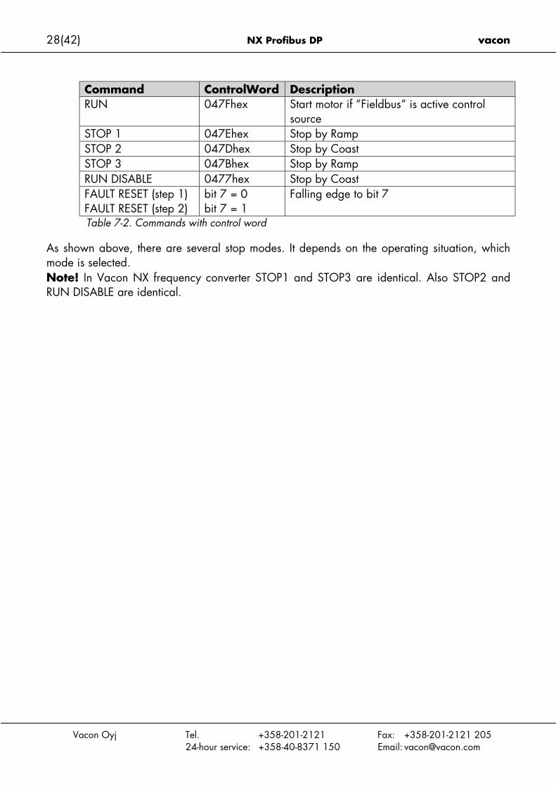
Command ControlWord DescriptionRUN 047Fhex Start motor if ”Fieldbus” is active control
sourceSTOP 1 047Ehex Stop by RampSTOP 2 047Dhex Stop by CoastSTOP 3 047Bhex Stop by RampRUN DISABLE 0477hex Stop by CoastFAULT RESET (step 1)FAULT RESET (step 2)
bit 7 = 0bit 7 = 1
Falling edge to bit 7
Table 7-2. Commands with control word
As shown above, there are several stop modes. It depends on the operating situation, whichmode is selected.Note! In Vacon NX frequency converter STOP1 and STOP3 are identical. Also STOP2 andRUN DISABLE are identical.

vacon NX Profibus DP 29(42)
Vacon Oyj Tel. +358-201-2121 Fax: +358-201-2121 20524-hour service: +358-40-8371 150 Email: [email protected]
7.4.2 Status wordSW ACT PD1 PD2 PD3 PD4 PD5 PD6 PD7 PD8
Information about the status of the device and messages is indicated in the Status word.The Status word is composed of 16 bits that have the following meanings:
Bit DescriptionValue = 0 Value = 1
0 Not Ready (initial) READY1 Not Ready READY2 DISABLE ENABLE3 NO FAULT FAULT ACTIVE4 STOP 2 OFF STOP 2 ON5 STOP 3 OFF STOP 3 ON6 START ENABLE START DISABLE7 No Warning Warning8 Reference ≠ Actual value Reference = Actual value9 Fieldbus control OFF Fieldbus control ON10 Not used Not used11 Not used Not used12 FC stopped Running13 FC not ready FC ready14 Not used Not used15 Not used Not usedTable 7-3. Status word bit descriptions

30(42) NX Profibus DP vacon
Vacon Oyj
7.4.3 State machine
The state machine describes the device status and the possible control sequence of the fre-quency converter. The state transitions can be generated by using the “Control word”. The“Status word” indicates the current status of the state machine. The modes INIT, STOP, RUNand FAULT (see Figure 7-2) correspond to the actual mode of the Frequency converter.
Figure 7-3.
Bit0=0
STOP 1 STOP by ramp Bit1=
Bit3=0
RUN DISABLE STOP Bit2=
DISABLE (Bit6=1) is one value of the “Status word”.Bit0=0 is one value of the “Control word”.
Power ON
Tel. +358-201-2121 Fax: +358-201-2121 20524-hour service: +358-40-8371 150 Email: [email protected]
DISABLE INIT Bit6=1
Reset faultBit7=0
xxxx x1xx xxxx x110
Bit7=1
Bit0=0
Fault
Bit0=1
Bit3=1
Bit4=1, Bit5=1, Bit6=1
READY 1 STOP Bit0=1
READY 2 STOP Bit1=1
ENABLE STOP Bit2=1
RUNNING RUN
NOT READY STOP Bit6=0
Bit0=0
FAULT ACTIVE FAULT Bit3=1
Bit1=0
STOP 2 STOP by coast Bit4=0
Bit2=0
STOP 3 STOP by ramp Bit5=0
0
0

vacon NX Profibus DP 31(42)
Vacon Oyj Tel. +358-201-2121 Fax: +358-201-2121 20524-hour service: +358-40-8371 150 Email: [email protected]
7.4.4 Reference 1CW REF PD1 PD2 PD3 PD4 PD5 PD6 PD7 PD8
This is the reference 1 to the frequency converter. Used normally as Speed reference.The allowed scaling is –10000...10000. In the application, the value is scaled in percentageof the frequency area between set minimum and maximum frequency.
-10000 = 100,00 % (Direction reverse)0 = 0,00 % (Direction forward)
10000 = 100,00 % (Direction forward)
7.4.5 Actual value 1SW ACT PD1 PD2 PD3 PD4 PD5 PD6 PD7 PD8
This is the actual value from the frequency converter. Used normally as Speed reference, withthe value between –10000...10000. In the application, the value is scaled in percentage offrequency area between set minimum and maximum frequency.
-10000 = 100,00 % (Direction reverse)0 = 0,00 % (Direction forward)
10000 = 100,00 % (Direction forward)
7.4.6 PD1…PD8
ProcessData Master -> Slave
CW REF PD1 PD2 PD3 PD4 PD5 PD6 PD7 PD8
The Master can write max. 8 additional setting values to the device with the help of the ProcessData. How these setting values are used is totally dependent on the application in use.
ProcessData Slave -> Master
SW ACT PD1 PD2 PD3 PD4 PD5 PD6 PD7 PD8
The master can read the frequency converter’s actual values using the process data variables.Depending on the used application, the contents are either standard or can be selected with aparameter.

32(42) NX Profibus DP vacon
Vacon Oyj Tel. +358-201-2121 Fax: +358-201-2121 20524-hour service: +358-40-8371 150 Email: [email protected]
Figure 7-4. Control of Process data (see APPENDIX 1)
Profibus DP master
PD1 PD2 PD3 PD4 PD5 PD6 PD7 PD8
VACON NX1 Output Frequency2 Motor Speed...
Selector Parameteror fixed variable
NXB1
vacon NX Profibus DP 33(42)
Vacon Oyj Tel. +358-201-2121 Fax: +358-201-2121 20524-hour service: +358-40-8371 150 Email: [email protected]
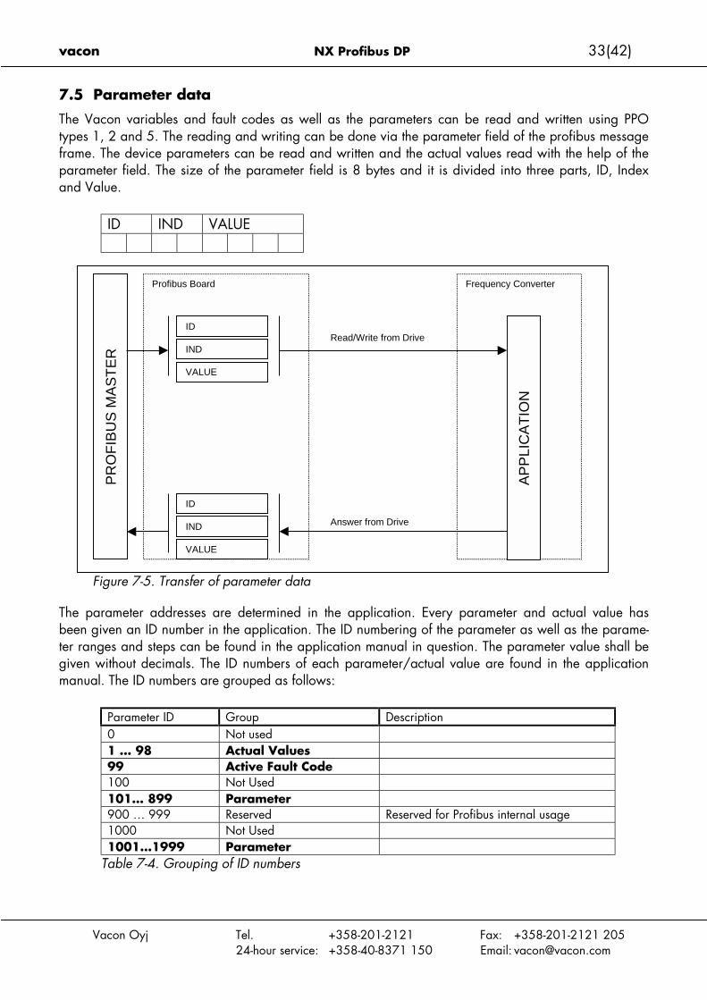
7.5 Parameter data
The Vacon variables and fault codes as well as the parameters can be read and written using PPOtypes 1, 2 and 5. The reading and writing can be done via the parameter field of the profibus messageframe. The device parameters can be read and written and the actual values read with the help of theparameter field. The size of the parameter field is 8 bytes and it is divided into three parts, ID, Indexand Value.
ID IND VALUE
Figure 7-5. Transfer of parameter data
The parameter addresses are determined in the application. Every parameter and actual value hasbeen given an ID number in the application. The ID numbering of the parameter as well as the parame-ter ranges and steps can be found in the application manual in question. The parameter value shall begiven without decimals. The ID numbers of each parameter/actual value are found in the applicationmanual. The ID numbers are grouped as follows:
Parameter ID Group Description0 Not used1 … 98 Actual Values99 Active Fault Code100 Not Used101… 899 Parameter900 … 999 Reserved Reserved for Profibus internal usage1000 Not Used1001…1999 Parameter
Table 7-4. Grouping of ID numbers
Frequency ConverterProfibus Board
ID
PR
OF
IBU
S M
AS
TE
R IND
VALUE
ID
IND
VALUE
AP
PLI
CA
TIO
N
Read/Write from Drive
Answer from Drive

34(42) NX Profibus DP vacon
Vacon Oyj Tel. +358-201-2121 Fax: +358-201-2121 20524-hour service: +358-40-8371 150 Email: [email protected]
7.5.1 Parameter field
Task and parameter ID
ID IND VALUE
ID byte1 ID byte2
15 14 13 12 11 10 9 8 7 6 5 4 3 2 1 0
Request/Response type SM Parameter Number (= Vacon ID number)
SM: Spontaneous bit (not used)
Request/Response types
Request Function Response Function
0 No request 0 No response
1 Read parameter value (word) 1 Parameter value ready (word)
2 Write parameter value (word) 7 Request rejected (+fault code)
Fault Numbers (if response = 7)
FaultNumber
Description
0 Illegal Parameter1 Parameter is read only ( e.g. actual
values)2 Parameter value is out of limits
17 Request temporarily rejected (e.g.can be changed only for STOP state)
18 Other fault101 Unknown request type
vacon NX Profibus DP 35(42)
Vacon Oyj Tel. +358-201-2121 Fax: +358-201-2121 20524-hour service: +358-40-8371 150 Email: [email protected]
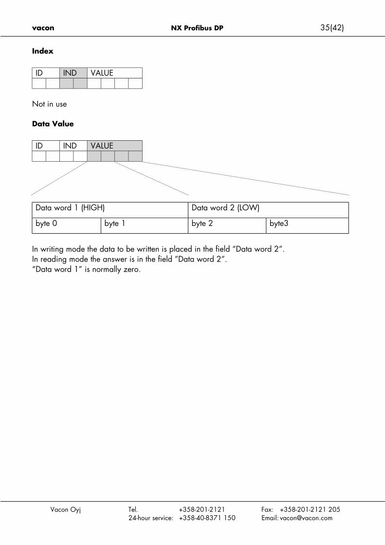
Index
ID IND VALUE
Not in use
Data Value
ID IND VALUE
Data word 1 (HIGH) Data word 2 (LOW)
byte 0 byte 1 byte 2 byte3
In writing mode the data to be written is placed in the field “Data word 2”.In reading mode the answer is in the field ”Data word 2”.“Data word 1” is normally zero.

36(42) NX Profibus DP vacon
Vacon Oyj Tel. +358-201-2121 Fax: +358-201-2121 20524-hour service: +358-40-8371 150 Email: [email protected]
7.6 Example messages
Example1, (PPO1 mode):
Read parameter number 102 (ID=102).Start frequency converter and set speed reference 50,00%.
Command Master - Slave:
ID 1066 hex 1 - Read parameter value066 - Parameter 102 (= e.g. maximum frequency )
IND 0000 hex 0000 - No meaningVALUE 0000 0000 hex 0000 0000 - No meaningCW 047F hex 04 7F- Start command (see chapter control word and state
machine)REF 1388 hex Speed ref. 50,00% (= 25,00 Hz if parameter min. frequency
0 Hz and max. frequency 50 Hz)
PPO1 frame (Parameter Field as Bold text):10 66 00 00 00 00 00 00 04 7F 13 88
Answer Slave - Master:
ID 1066 hex 1 - Parameter value ready066 - Parameter 102 (= Maximum frequency )
IND 0000 hex 0000 - No meaningVALUE 0000 1388 hex 0000 1388 - Parameter value = 1388hex ( 50,00 Hz)SW 0000 hex 0000 - frequency converter status (see chapter status word
and state machine)ACT 0000 hex Current speed 0,00% (= 0,00 Hz if parameter min. fre-
quency 0 Hz and max. frequency 50 Hz)
PPO1 frame (Parameter Field as Bold text):10 66 00 00 00 00 13 88 00 00 00 00

vacon NX Profibus DP 37(42)
Vacon Oyj Tel. +358-201-2121 Fax: +358-201-2121 20524-hour service: +358-40-8371 150 Email: [email protected]
Example 2, (PPO1 mode):
Write to parameter number 700 (par. 2.7.1) value 2.Keep Run mode on and Send speed reference 75,00%.
Command Master - Slave:
ID 22BC hex 2 - Write parameter value2BC - Parameter 700
IND 0000 hex 0000 - No meaningVALUE 0000 0002 hex 0000 0002 - Parameter valueCW 047F hex 04 7F- Start command (see chapter control word and state
machine)REF 1D4C hex Speed ref. 75,00% (= 37,50 Hz if parameter min. fre-
quency 0 Hz and max. frequency 50 Hz)
PPO1 frame ( Parameter Field as Bold text)::
22 BC 00 00 00 00 00 02 04 7F 1D 4C
Answer Slave - Master:
ID 12BC hex 1 - Parameter value ready2BC - Parameter 700 (= Response to reference fault )
IND 0000 hex 0000 - No meaningVALUE 0000 0032 hex 0000 0000 – No meaningSW 0337 hex 0337- frequency converter status (see chapter status word
and state machine)ACT 09C4 hex Current speed 25,00% (= 12,50 Hz if parameter min.
frequency 0 Hz and max. frequency 50 Hz)
PPO1 frame ( Parameter Field as Bold text):12 BD 00 00 00 00 00 00 03 37 09 C4
38(42) NX Profibus DP vacon
Vacon Oyj Tel. +358-201-2121 Fax: +358-201-2121 20524-hour service: +358-40-8371 150 Email: [email protected]
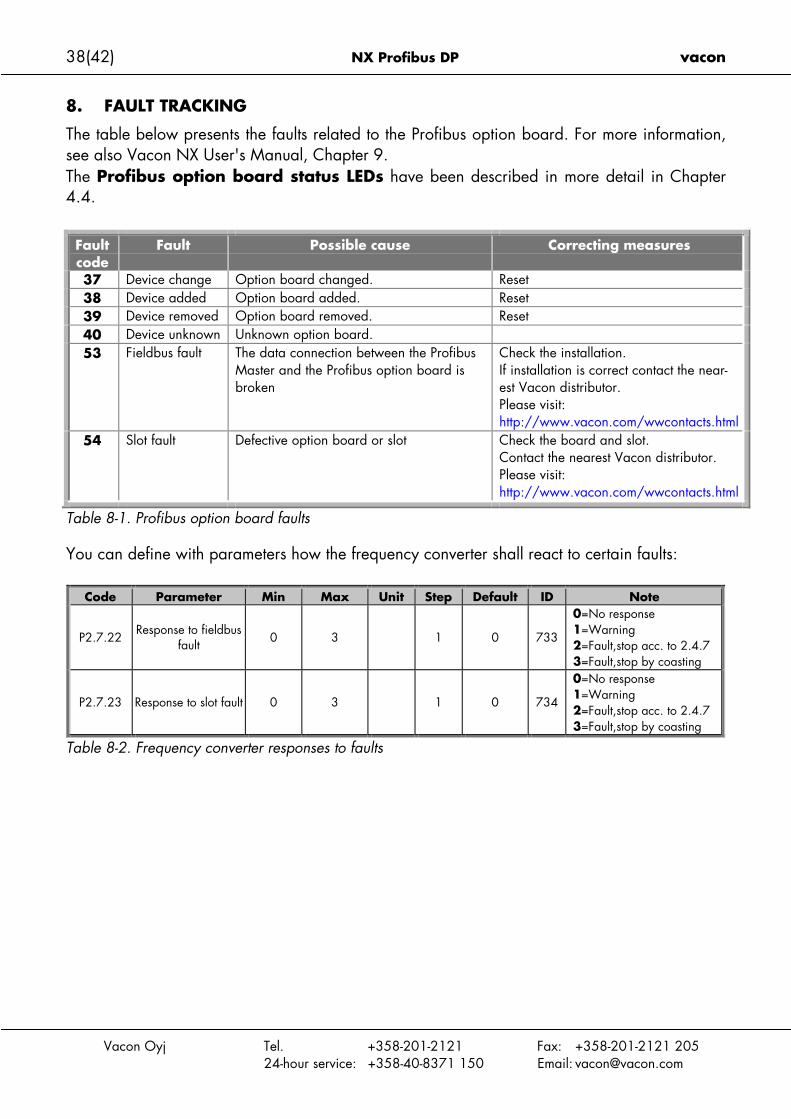
8. FAULT TRACKING
The table below presents the faults related to the Profibus option board. For more information,see also Vacon NX User's Manual, Chapter 9.The Profibus option board status LEDs have been described in more detail in Chapter4.4.
Faultcode
Fault Possible cause Correcting measures
37 Device change Option board changed. Reset38 Device added Option board added. Reset39 Device removed Option board removed. Reset40 Device unknown Unknown option board.53 Fieldbus fault The data connection between the Profibus
Master and the Profibus option board isbroken
Check the installation.If installation is correct contact the near-est Vacon distributor.Please visit:http://www.vacon.com/wwcontacts.html
54 Slot fault Defective option board or slot Check the board and slot.Contact the nearest Vacon distributor.Please visit:http://www.vacon.com/wwcontacts.html
Table 8-1. Profibus option board faults
You can define with parameters how the frequency converter shall react to certain faults:
Code Parameter Min Max Unit Step Default ID Note
P2.7.22Response to fieldbus
fault 0 3 1 0 733
0=No response1=Warning2=Fault,stop acc. to 2.4.73=Fault,stop by coasting
P2.7.23 Response to slot fault 0 3 1 0 734
0=No response1=Warning2=Fault,stop acc. to 2.4.73=Fault,stop by coasting
Table 8-2. Frequency converter responses to faults

vacon NX Profibus DP 39(42)
Vacon Oyj Tel. +358-201-2121 Fax: +358-201-2121 20524-hour service: +358-40-8371 150 Email: [email protected]
9. Type files
9.1 GSD-file (“Profibus Support Disk” files: vac29500.GSD, vac29500.GSE)#Profibus_DP
GSD_Revision = 1
Vendor_Name = "Vaasa Control"
Model_Name = "Vacon NX"
Revision = "1.0"
Ident_Number = 0x9500
Protocol_Ident = 0
Station_Type = 0
FMS_supp = 0
Hardware_Release = "HW1.0"
Software_Release = "SW1.0"
9.6_supp = 1
19.2_supp = 1
93.75_supp = 1
187.5_supp = 1
500_supp = 1
1.5M_supp = 1
3M_supp = 1
6M_supp = 1
12M_supp = 1
MaxTsdr_9.6 = 60
MaxTsdr_19.2 = 60
MaxTsdr_93.75 = 60
MaxTsdr_187.5 = 60
MaxTsdr_500 = 100
MaxTsdr_1.5M = 150
MaxTsdr_3M = 250
MaxTsdr_6M = 450MaxTsdr_12M = 800
Redundancy = 0
Repeater_Ctrl_Sig = 0
24V_Pins = 0
Implementation_Type = "SPC3"
Freeze_Mode_supp = 1
Sync_Mode_supp = 1
Auto_Baud_supp = 1
Set_Slave_Add_supp = 0
Min_Slave_Intervall = 20
Modular_Station = 1
Max_Module = 5
Max_Input_Len = 28
Max_Output_Len = 28
Max_Data_Len = 56
Modul_Offset = 0
Slave_Family = 1
Fail_Safe = 1
Max_Diag_Data_Len = 6
Module = "VACON PPO 1" 0xF3, 0xF1
EndModule;
Module = "VACON PPO 2" 0xF3, 0xF5
EndModule;
Module = "VACON PPO 3" 0xF1
EndModule;Module = "VACON PPO 4" 0xF5
EndModule;
Module = "VACON PPO 5" 0xF3, 0xF9
EndModule;
Module = "___________special____________" 0x00
EndModule
Module = "PPO 2" 0xF3, 0xF1, 0xF1, 0xF1
EndModule
Module = "PPO 4" 0xF1, 0xF1, 0xF1
EndModule
Module = "PPO 5" 0xF3, 0xF1, 0xF1, 0xF1, 0xF1,0xF1EndModule

40(42) NX Profibus DP vacon
Vacon Oyj Tel. +358-201-2121 Fax: +358-201-2121 20524-hour service: +358-40-8371 150 Email: [email protected]
APPENDIX 1
Process Data OUT (Slave """" Master)
The fieldbus master can read the frequency converter’s actual values using process data vari-ables.Basic, Standard, Local/Remote, Multi-Step, PID control and Pump and fan control applicationsuse process data as follows:
Data Value Unit ScaleProcess data OUT 1 Output Frequency Hz 0,01 HzProcess data OUT 2 Motor Speed rpm 1 rpmProcess data OUT 3 Motor Current A 0,1 AProcess data OUT 4 Motor Torque % 0,1 %Process data OUT 5 Motor Power % 0,1 %Process data OUT 6 Motor Voltage V 0,1 VProcess data OUT 7 DC link voltage V 1 VProcess data OUT 8 Active Fault Code - -
The Multipurpose application has a selector parameter for every Process Data. The monitoringvalues and drive parameters can be selected using the ID number (see NX All in One Applica-tion Manual, Tables for monitoring values and parameters). Default selections are as in the ta-ble above.
Process Data IN (Master -> Slave)ControlWord, Reference and Process Data are used with All-inOne applications as follows:
Basic, Standard, Local/Remote, Multi-Step applications
Data Value Unit ScaleReference Speed Reference % 0.01%ControlWord Start/Stop Command
Fault reset Command- -
PD1 – PD8 Not used - -

vacon NX Profibus DP 41(42)
Vacon Oyj Tel. +358-201-2121 Fax: +358-201-2121 20524-hour service: +358-40-8371 150 Email: [email protected]
Multipurpose control application
Data Value Unit ScaleReference Speed Reference % 0.01%ControlWord Start/Stop Command
Fault reset Command- -
Process Data IN1 Torque Reference % 0.1%Process Data IN2 Free Analogue INPUT % 0.01%Process Data IN3 Adjust Input % 0.01%PD3 – PD8 Not Used - -
PID control and Pump and fan control applications
Data Value Unit ScaleReference Speed Reference % 0.01%ControlWord Start/Stop Command
Fault reset Command- -
Process Data IN1 Reference for PID controller % 0.01%Process Data IN2 Actual Value 1 to PID con-
troller% 0.01%
Process Data IN3 Actual Value 2 to PID con-troller
% 0.01%
PD4–PD8 Not Used - -

R65
Tel: +358-(Fax: +358-(0)2
24-hour service: +358-(0)4E-mail: vacon
ud71
1.do
c14
.01.
02 1
3:19
Vacon PlcP.O.Box 25unsorintie 7
381 VAASAFINLAND
0)201-212101-212 2050-8371 [email protected]


