Serial Number Decal Visit our website at www.proform.com new products, prizes, fitness tips, and much more! USER’S MANUAL CAUTION Read all precautions and instructions in this manual before using this equipment. Keep this manual for future reference. Model No. 831.285281 Serial No. Patent Pending SEARS, ROEBUCK AND CO., HOFFMAN ESTATES, IL 60179 Write the serial number in the space above for future reference.
Transcript
SerialNumberDecal
Visit our website at
www.proform.comnew products, prizes,
fitness tips, and much more!
USER’S MANUAL
CAUTIONRead all precautions andinstructions in this manualbefore using this equipment.Keep this manual for futurereference.
Model No. 831.285281Serial No.
Patent Pending
SEARS, ROEBUCK AND CO.,HOFFMAN ESTATES, IL 60179
Write the serial number in thespace above for future reference.
PROFORM is a registered trademark of ICON Health & Fitness, Inc.
3
IMPORTANT PRECAUTIONS
WARNING: To reduce the risk of serious injury, read the following important precau-tions before using the elliptical crosstrainer.
1. Read all instructions in this manual beforeusing the elliptical crosstrainer.
2. It is the responsibility of the owner to ensurethat all users of the elliptical crosstrainerare adequately informed of all precautions.
3. Place the elliptical crosstrainer on a levelsurface, with a mat beneath it to protect thefloor or carpet. Keep the elliptical crosstrain-er indoors, away from moisture and dust.
4. Inspect and properly tighten all parts regu-larly. Replace any worn parts immediately.
5. Keep children under 12 and pets away fromthe elliptical crosstrainer at all times.
6. The elliptical crosstrainer should not be usedby persons weighing more than 250 pounds.
7. Wear appropriate exercise clothing whenusing the elliptical crosstrainer. Always wearathletic shoes for foot protection.
8. Always hold the handgrip pulse sensor or thehandlebars when mounting, dismounting, orusing the elliptical crosstrainer.
9. The pulse sensor is not a medical device.Various factors may affect the accuracy ofheart rate readings. The pulse sensor isintended only as an exercise aid in determin-ing heart rate trends in general.
10. Keep your back straight when using the ellip-tical crosstrainer; do not arch your back.
11. If you feel pain or dizziness at any timewhile exercising, stop immediately andbegin cooling down.
12. When you stop exercising, allow the pedalsto slowly come to a stop.
13. The elliptical crosstrainer is intended for home use only. Do not use the ellipticalcrosstrainer in a commercial, rental, or insti-tutional setting.
WARNING: Before beginning this or any exercise program, consult your physician.This is especially important for persons over the age of 35 or persons with pre-existing health prob-lems. Read all instructions before using. SEARS assumes no responsibility for personal injury orproperty damage sustained by or through the use of this product.
4
BEFORE YOU BEGINCongratulations for selecting the new PROFORM®
700 CARDIO CROSSTRAINER. The PROFORM® 700is an incredibly smooth exerciser that moves your feetin a natural elliptical path, minimizing the impact onyour knees and ankles. And the unique PROFORM®
700 features adjustable resistance and a state-of-the-art console to help you get the most from your exer-cise. Welcome to a whole new world of natural, ellipti-cal-motion exercise from PROFORM.
For your benefit, read this manual carefully beforeyou use the elliptical crosstrainer. If you have addi-
tional questions, please call our toll-free HELPLINE at1-800-736-6879, Monday through Saturday, 7 a.m.until 7 p.m. Central Time (excluding holidays). To helpus assist you, please note the product model numberand serial number before calling. The model numberis 831.285281. The serial number can be found on adecal attached to the elliptical crosstrainer (see thefront cover of this manual for the location of the decal).
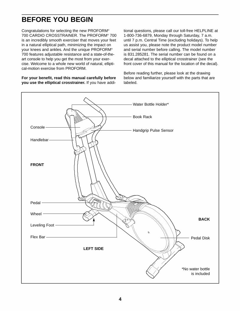
Before reading further, please look at the drawingbelow and familiarize yourself with the parts that arelabeled.
Handgrip Pulse Sensor
Handlebar
FRONT
BACK
LEFT SIDE
Flex Bar Pedal Disk
*No water bottleis included
Wheel
Pedal
Console
Book Rack
Water Bottle Holder*
Leveling Foot
5
ASSEMBLY
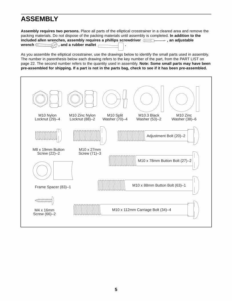
Assembly requires two persons. Place all parts of the elliptical crosstrainer in a cleared area and remove thepacking materials. Do not dispose of the packing materials until assembly is completed. In addition to theincluded allen wrenches, assembly requires a phillips screwdriver , an adjustablewrench , and a rubber mallet .
As you assemble the elliptical crosstrainer, use the drawings below to identify the small parts used in assembly.The number in parenthesis below each drawing refers to the key number of the part, from the PART LIST onpage 22. The second number refers to the quantity used in assembly. Note: Some small parts may have beenpre-assembled for shipping. If a part is not in the parts bag, check to see if it has been pre-assembled.
M10 x 112mm Carriage Bolt (34)–4
Adjustment Bolt (20)–2
M10 x 88mm Button Bolt (63)–1
M10 x 78mm Button Bolt (27)–2
M10.3 BlackWasher (53)–2
M8 x 19mm ButtonScrew (22)–2
M4 x 16mmScrew (66)–2
M10 x 27mmScrew (71)–3
M10 ZincWasher (38)–6
M10 SplitWasher (70)–4
M10 Zinc NylonLocknut (88)–2
M10 NylonLocknut (29)–4
Frame Spacer (83)–1
6
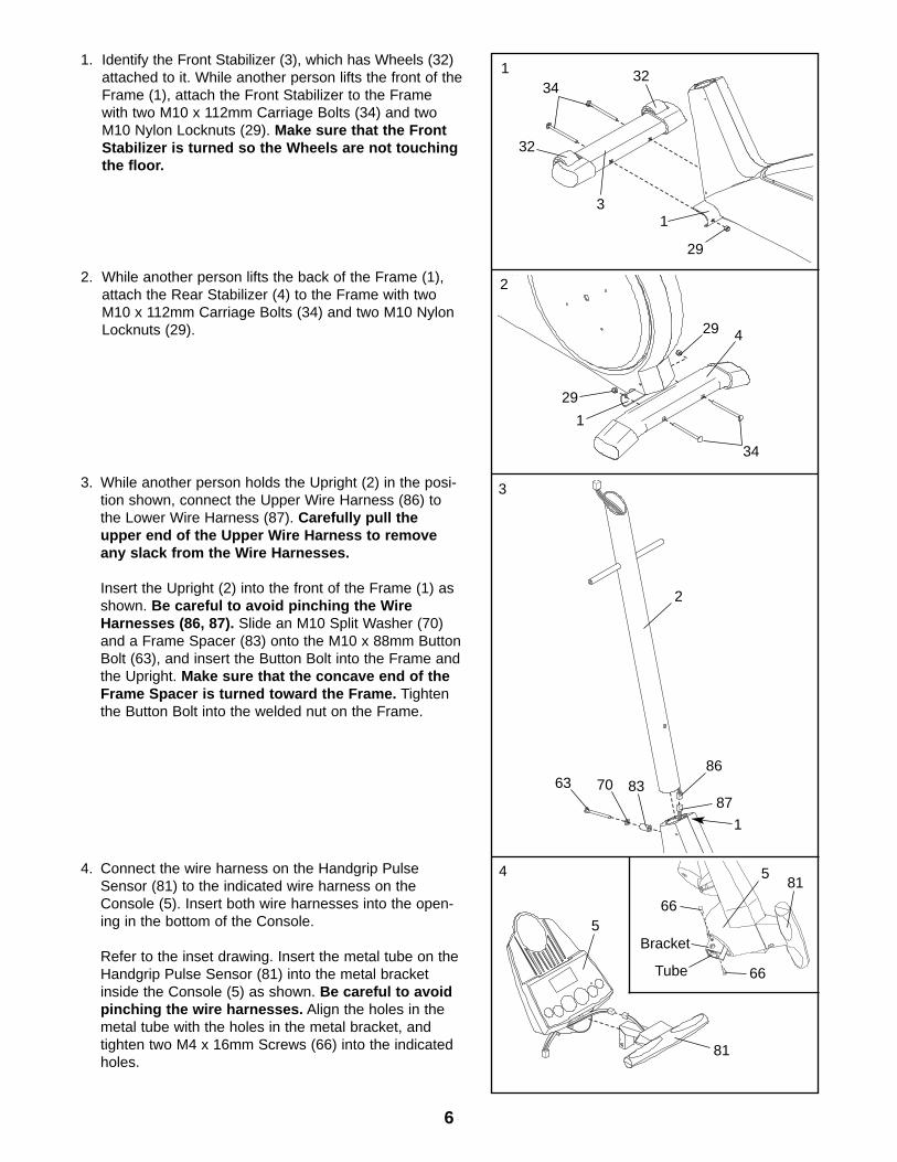
1. Identify the Front Stabilizer (3), which has Wheels (32)attached to it. While another person lifts the front of theFrame (1), attach the Front Stabilizer to the Framewith two M10 x 112mm Carriage Bolts (34) and twoM10 Nylon Locknuts (29). Make sure that the FrontStabilizer is turned so the Wheels are not touchingthe floor.
3
29
32
3234
1
1
2. While another person lifts the back of the Frame (1),attach the Rear Stabilizer (4) to the Frame with twoM10 x 112mm Carriage Bolts (34) and two M10 NylonLocknuts (29).
34
4
1
3
2
86
87
1
63 8370
3. While another person holds the Upright (2) in the posi-tion shown, connect the Upper Wire Harness (86) tothe Lower Wire Harness (87). Carefully pull theupper end of the Upper Wire Harness to removeany slack from the Wire Harnesses.
Insert the Upright (2) into the front of the Frame (1) asshown. Be careful to avoid pinching the WireHarnesses (86, 87). Slide an M10 Split Washer (70)and a Frame Spacer (83) onto the M10 x 88mm ButtonBolt (63), and insert the Button Bolt into the Frame andthe Upright. Make sure that the concave end of theFrame Spacer is turned toward the Frame. Tightenthe Button Bolt into the welded nut on the Frame.
4. Connect the wire harness on the Handgrip PulseSensor (81) to the indicated wire harness on theConsole (5). Insert both wire harnesses into the open-ing in the bottom of the Console.
Refer to the inset drawing. Insert the metal tube on theHandgrip Pulse Sensor (81) into the metal bracketinside the Console (5) as shown. Be careful to avoidpinching the wire harnesses. Align the holes in themetal tube with the holes in the metal bracket, andtighten two M4 x 16mm Screws (66) into the indicatedholes.
81
566
5
Bracket
66
814
2
29
29
Tube
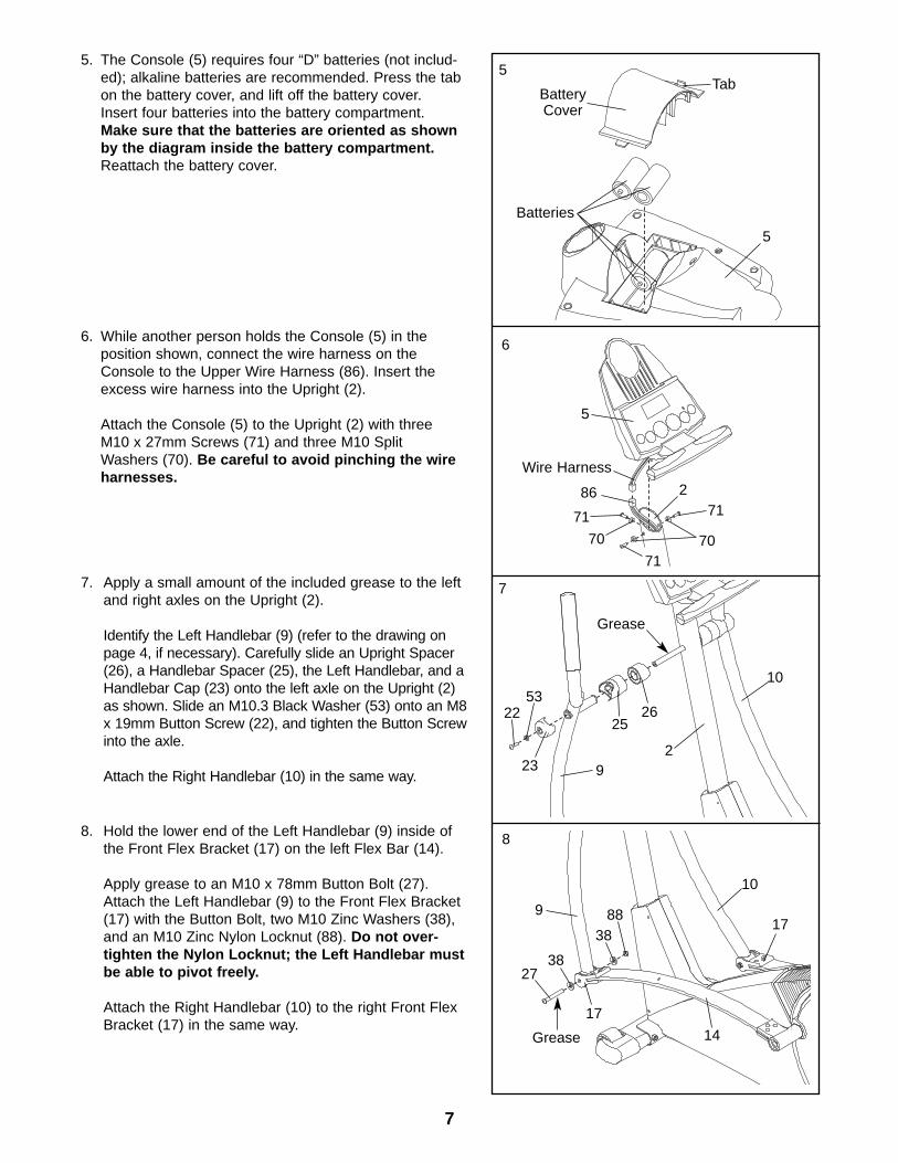
8. Hold the lower end of the Left Handlebar (9) inside ofthe Front Flex Bracket (17) on the left Flex Bar (14).
Apply grease to an M10 x 78mm Button Bolt (27).Attach the Left Handlebar (9) to the Front Flex Bracket(17) with the Button Bolt, two M10 Zinc Washers (38),and an M10 Zinc Nylon Locknut (88). Do not over-tighten the Nylon Locknut; the Left Handlebar mustbe able to pivot freely.
Attach the Right Handlebar (10) to the right Front FlexBracket (17) in the same way.
17
17
14
2738
3888
Grease
7
6. While another person holds the Console (5) in theposition shown, connect the wire harness on theConsole to the Upper Wire Harness (86). Insert theexcess wire harness into the Upright (2).
Attach the Console (5) to the Upright (2) with threeM10 x 27mm Screws (71) and three M10 SplitWashers (70). Be careful to avoid pinching the wireharnesses.
6
5
867171
7. Apply a small amount of the included grease to the leftand right axles on the Upright (2).
Identify the Left Handlebar (9) (refer to the drawing onpage 4, if necessary). Carefully slide an Upright Spacer(26), a Handlebar Spacer (25), the Left Handlebar, and aHandlebar Cap (23) onto the left axle on the Upright (2)as shown. Slide an M10.3 Black Washer (53) onto an M8x 19mm Button Screw (22), and tighten the Button Screwinto the axle.
Attach the Right Handlebar (10) in the same way.
Grease
7
8
2
Wire Harness
7070
71
2625
92
10
23
5322
9
10
5. The Console (5) requires four “D” batteries (not includ-ed); alkaline batteries are recommended. Press the tabon the battery cover, and lift off the battery cover.Insert four batteries into the battery compartment.Make sure that the batteries are oriented as shownby the diagram inside the battery compartment.Reattach the battery cover.
5
5
Tab
Batteries
BatteryCover
INSTALLING THE RECEIVER FOR THE OPTIONAL CHEST PULSE SENSOR
If you purchase the optional chest pulse sensor (refer to page 20), follow the steps below to install the receiverand the jumper wire included with the chest pulse sensor.
1. Remove the four indicated screws from the back of theConsole (5). Lift off the front of the Console.
2. Plug the jumper wire (A) into the indicated jack on theConsole (5). Connect the other end of the jumper wireto the wire on the receiver (B).
Next, peel the paper off the adhesive pad on the backof the receiver (B). Orient the receiver as shown, andpress it onto the Console (5) in the indicated location.
Refer to step 1 above. Reattach the front of theConsole (5) with the four screws. Make sure that nowires are pinched.
8
10. Make sure that all parts of the elliptical crosstrainer are properly tightened. Note: Some hardware maybe left over after assembly is completed. To protect the floor or carpet from damage, place a mat under theelliptical crosstrainer.
920
15
14 38
13
9. Identify the Left Pedal (13). Attach the Left Pedal to theleft Flex Bar (14) with an Adjustment Bolt (20), an M10Zinc Washer (38), and an Adjustment Knob (15) asshown. Note: The Left Pedal can be attached in any offive positions (see HOW TO ADJUST THE PEDALS onpage 9).
Attach the Right Pedal (not shown) in the same way.Make sure that both Pedals are in the same position.
B
5
Jack
5
Screws
LiftHere
1
A
Cylinder
2
9
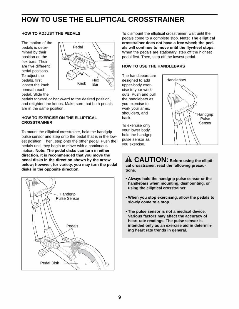
HOW TO USE THE ELLIPTICAL CROSSTRAINER
HOW TO ADJUST THE PEDALS
The motion of thepedals is deter-mined by theirposition on theflex bars. Theirare five differentpedal positions.To adjust thepedals, firstloosen the knobbeneath eachpedal. Slide thepedals forward or backward to the desired position,and retighten the knobs. Make sure that both pedalsare in the same position.
HOW TO EXERCISE ON THE ELLIPTICALCROSSTRAINER
To mount the elliptical crosstrainer, hold the handgrippulse sensor and step onto the pedal that is in the low-est position. Then, step onto the other pedal. Push thepedals until they begin to move with a continuousmotion. Note: The pedal disks can turn in eitherdirection. It is recommended that you move thepedal disks in the direction shown by the arrowbelow; however, for variety, you may turn the pedaldisks in the opposite direction.
To dismount the elliptical crosstrainer, wait until thepedals come to a complete stop. Note: The ellipticalcrosstrainer does not have a free wheel; the ped-als will continue to move until the flywheel stops.When the pedals are stationary, step off the highestpedal first. Then, step off the lowest pedal.
HOW TO USE THE HANDLEBARS
The handlebars aredesigned to addupper-body exer-cise to your work-outs. Push and pullthe handlebars asyou exercise towork your arms,shoulders, andback.
To exercise onlyyour lower body,hold the handgrippulse sensor asyou exercise.
CAUTION: Before using the ellipti-cal crosstrainer, read the following precau-tions.
• Always hold the handgrip pulse sensor or thehandlebars when mounting, dismounting, orusing the elliptical crosstrainer.
• When you stop exercising, allow the pedals toslowly come to a stop.
• The pulse sensor is not a medical device.Various factors may affect the accuracy ofheart rate readings. The pulse sensor isintended only as an exercise aid in determin-ing heart rate trends in general.
Pedals
Pedal Disk
HandgripPulse Sensor
Handlebars
HandgripPulse
Sensor
KnobFlexBar
Pedal
10
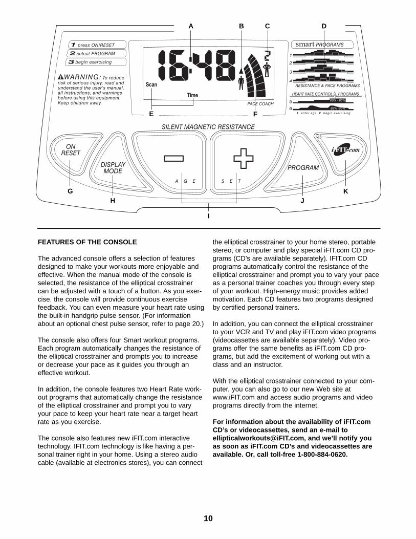
FEATURES OF THE CONSOLE
The advanced console offers a selection of featuresdesigned to make your workouts more enjoyable andeffective. When the manual mode of the console isselected, the resistance of the elliptical crosstrainercan be adjusted with a touch of a button. As you exer-cise, the console will provide continuous exercisefeedback. You can even measure your heart rate usingthe built-in handgrip pulse sensor. (For informationabout an optional chest pulse sensor, refer to page 20.)
The console also offers four Smart workout programs.Each program automatically changes the resistance ofthe elliptical crosstrainer and prompts you to increaseor decrease your pace as it guides you through aneffective workout.
In addition, the console features two Heart Rate work-out programs that automatically change the resistanceof the elliptical crosstrainer and prompt you to varyyour pace to keep your heart rate near a target heartrate as you exercise.
The console also features new iFIT.com interactivetechnology. IFIT.com technology is like having a per-sonal trainer right in your home. Using a stereo audiocable (available at electronics stores), you can connect
the elliptical crosstrainer to your home stereo, portablestereo, or computer and play special iFIT.com CD pro-grams (CD’s are available separately). IFIT.com CDprograms automatically control the resistance of theelliptical crosstrainer and prompt you to vary your paceas a personal trainer coaches you through every stepof your workout. High-energy music provides addedmotivation. Each CD features two programs designedby certified personal trainers.
In addition, you can connect the elliptical crosstrainerto your VCR and TV and play iFIT.com video programs(videocassettes are available separately). Video pro-grams offer the same benefits as iFIT.com CD pro-grams, but add the excitement of working out with aclass and an instructor.
With the elliptical crosstrainer connected to your com-puter, you can also go to our new Web site atwww.iFIT.com and access audio programs and videoprograms directly from the internet.
For information about the availability of iFIT.comCD’s or videocassettes, send an e-mail [email protected], and we’ll notify youas soon as iFIT.com CD’s and videocassettes areavailable. Or, call toll-free 1-800-884-0620.
E
GH
F
K
I
J
A B C D
11
CONSOLE DESCRIPTION
Refer to the drawing on page 10. Note: If there is athin sheet of clear plastic on the face of the con-sole, remove it.
A. Exercise feedback display—This display featuresseven modes that give you instant exercise feed-back: your current speed, the elapsed time (or thetime remaining in a Smart program or a Heart Rateprogram), the distance that you have pedaled, theresistance level, the approximate number of calo-ries you have burned, your power output in watts,and your heart rate (when you use the handgrippulse sensor or the optional chest pulse sensor[refer to page 20 for information about the chestpulse sensor]). If the scan mode is selected, thedisplay will change from one mode to the nextevery six seconds. Or, you can select a single modefor continuous display.
Note: The console can show speed and distancein either miles or kilometers. To change the unitof measurement, hold down the On/Reset buttonfor six seconds. The mode indicators (see E.below) will show which unit of measurement isselected. When the batteries are replaced, it maybe necessary to reselect the desired unit of mea-surement.
B. Increase and decrease arrows—During Smart pro-grams, Heart Rate programs, and iFIT.com pro-grams, these arrows will prompt you to increase ordecrease your pace to match the target pace.
C. Manual mode/program indicator—When a Smartprogram is selected, the upper right corner of thedisplay will show a 1, 2, 3, or 4, depending onwhich Smart program is selected. When a HeartRate program is selected, the upper right corner ofthe display will show a 5 or 6. When the iFIT.commode is selected, the upper right corner will showthe letters IF. When the manual mode is selected,the upper right corner will be blank.
D. Program profiles—These profiles show how theresistance of the elliptical crosstrainer and the tar-get pace will change during Smart programs andHeart Rate programs. For example, profile number3 shows that during Smart program 3, both theresistance and the pace will gradually increase dur-ing the first half of the program, and then graduallydecrease during the last half.
E. Feedback mode indicators—These indicators showwhich feedback mode (scan, speed, time, distance,resistance level, calories, watts, or heart rate) is
currently shown. Note: When the distance isshown, the word Miles or the letters Kms willappear; when your speed is shown, the letters MPHor Km/H will appear.
F. Pace bar graphs—When the manual mode isselected, only the left bar graph will appear. Thisbar graph represents your exercise pace. As youincrease or decrease your pace, additional bars willappear or disappear on the bar graph. When aSmart program, a Heart Rate program, or theiFIT.com mode is selected, both bar graphs willappear. The left bar graph represents your exercisepace, and the right bar graph represents a targetpace. During the program, the target pace willperiodically change. As the right bar graphchanges, simply adjust your pace so that the samenumber of bars appear on both bar graphs.Important: The target pace is a goal pace. Youractual pace may be slower than the target pace,especially during the first few months of yourexercise program. Make sure to exercise at apace that is comfortable for you.
G. On/Reset button—When the console is off, pressingthis button will turn on the display. When the consoleis on, pressing this button will reset the display.This button is also used to select the unit of mea-surement for speed and distance (see A. at the left).
H. Display Mode button—This button is used to selectthe feedback modes. The modes will be selected inthe following order: scan, speed, time, distance,resistance level, calories, watts, and heart rate(when the handgrip pulse sensor or the optionalchest pulse sensor is used).
I. + and – buttons—These buttons control the resis-tance of the elliptical crosstrainer. There are tenresistance levels; level 10 is the most challenging.These buttons are also used to enter your agewhen a Heart Rate program is selected.
J. Program button—This button is used to select themanual mode, Smart programs, and Heart Rateprograms.
K. IFIT.com button—This button is used to select theiFIT.com mode. The indicator on the button will lightwhen the iFIT.com mode is selected.
To use the manual mode of the console, refer topage 12. To use a Smart program, refer to page 13.To use a Heart Rate program, refer to page 14. Touse iFIT.com CD’s or videos, refer to page 18. Touse a program directly from our Web site, refer topage 19.
12
Turn on the console.
Note: The console requires four “D” batteries (notincluded). If you have not installed batteries, referto step 5 on page 7 and install batteries.
To turn on the console, press the On/Reset buttonor begin pedaling. Note: When the console isturned on, the resistance of the ellipticalcrosstrainer will automatically change to level 1, ifit is not already at level 1.
Select the manual mode.
Each time theconsole isturned on, themanual modewill be select-ed. If a Smartprogram, aHeart Rate pro-gram, or the iFIT.com mode has been selected,select the manual mode by pressing the Programbutton repeatedly until the upper right corner ofthe display is blank.
Begin exercising and adjust the resistance ofthe elliptical crosstrainer.
As you exercise, adjust the resistance of theelliptical crosstrainer as desired by pressing the +and – buttons. There are ten resistance levels;level 10 is the most challenging. Note: After thebuttons are pressed, it will take a few seconds forthe selected setting to be reached.
Follow your progress with the feedback modesand the left bar graph.
When the con-sole is turnedon, the scanmode will beselected. Asyou exercise,the display willshow your cur-rent speed, the elapsed time, the distance thatyou have pedaled, the current resistance level,the approximate number of calories you haveburned, and your power output in watts. In addi-tion, your heart rate will be shown when you usethe handgrip pulse sensor (refer to step 5 below)
or the optional chest pulse sensor (refer to page20). Note: Each time the resistance levelchanges, the console will show the resistancelevel for six seconds. In addition, when a Smartprogram or a Heart Rate program is selected, thedisplay will show the time remaining in the pro-gram instead of the elapsed time.
In addition, the left bar graph will appear in the dis-play to show your exercise pace. As you increaseor decrease your pace, additional bars will appearor disappear on the bar graph.
If desired, you can select a single feedback modefor continuous display. Press the Display Modebutton repeatedly until only the MPH (or Km/H),Time, Miles (or Kms), Resist., Cals., or Wattsindicator appears in the display. Make sure thatthe Scan indicator does not appear.
Measure your heart rate if desired.
Note: If there are thin sheets of plastic on themetal contacts on the handgrip pulse sensor,peel off the plastic.
To use the hand-grip pulse sen-sor, place yourhands on themetal contacts.Your palms mustbe on the uppercontacts andyour fingersmust be touching the lower contacts. Avoid mov-ing your hands. When your pulse is detected, theheart-shaped indicator in the display will flasheach time your heart beats. After a moment, twodashes (– –) will appear and then your heart ratewill be shown.
For the most accurate heart rate reading, continueto hold the handgrips for about 15 seconds. Note:When you first hold the handgrips, the display willshow your heart rate continuously for 15 sec-onds. The display will then show your heart ratealong with the other feedback modes.
When you are finished exercising, the consolewill automatically turn off after five minutes.
If the pedals are not moved and the console but-tons are not pressed for five minutes, the con-sole will automatically turn off to conservethe batteries.
6
5
4
3
2
1
HOW TO USE THE MANUAL MODE
This corner should be blank
MetalContacts
13
Turn on the console.
Refer to step 1 on page 12.
Select one of the four Smart programs.
Each time theconsole is turnedon, the manualmode will beselected. Toselect a Smartprogram, pressthe Program but-ton repeatedly until the number 1, 2, 3, or 4appears in the upper right corner of the display.
The profiles numbered 1 through 4 on the rightside of the console show the resistance and pacesettings for the Smart programs. For example,profile number 3 shows that when Smart program3 is selected, both the resistance and the pacewill gradually increase during the first half of theprogram, and then decrease during the last half.
Start the program.
To start the program, simply begin exercising.Each Smart program consists of twenty, one-minute periods. One resistance setting and onepace setting are programmed for each period.(The same resistance setting and/or pace settingmay be programmed for consecutive periods.)
During the program, the resistance of the ellipticalcrosstrainer will automatically change as shownby the applicable profile on the console. If the cur-rent resistance level is too high or too low, youcan change the resistance level by pressing the +and – buttons. However, when the current periodof the program is completed, the resistance levelwill automatically change if a different resistancesetting is programmed for the next period.
The pace set-tings for the pro-gram will beshown by theright bar graph inthe display. (Theleft bar graph willshow your actualexercise pace.) As the right bar graph changesduring the program, simply increase or decreaseyour pace so that the same number of barsappear on both bar graphs. If your pace is slowerthan the current pace setting, the increase arrowwill appear in the display to prompt you toincrease your pace; if your pace is faster than thepace setting, the decrease arrow will appear.Important: The pace settings for the programare intended only to provide a goal. Your actu-al pace may be slower than the pace settings,especially during the first few months of yourexercise program. Make sure to exercise at apace that is comfortable for you.
During the program, the display will show the timeremaining in the program. When no time remains,the program will be completed. If you continueexercising after the program is completed, thedisplay will continue to show your exercise feed-back.
Follow your progress with the feedback modes.
Refer to step 4 on page 12.
Measure your heart rate if desired.
See step 5 on page 12.
When you are finished exercising, the consolewill automatically turn off after five minutes.
Refer to step 6 on page 12.
6
5
43
2
1
HOW TO USE A SMART PROGRAM
Increase Arrow
14
Each Heart Rate program helps you to keep yourheart rate near a certain percentage of your maximumheart rate during your workout. (Your maximum heartrate is estimated by subtracting your age from 220.For example, if you are 25 years old, your maximumheart rate is 195.) Heart Rate program 5 is designedto keep your heart rate between 65% and 85% of yourmaximum heart rate while you exercise; Heart Rateprogram 6 is designed to keep your heart ratebetween 65% and 80% of your maximum heart rate.
Follow the steps below to use a Heart Rate program.
Turn on the console.
Refer to step 1 on page 12.
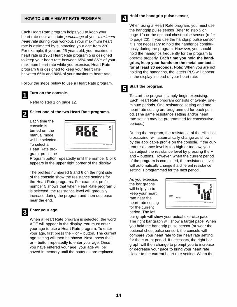
Select one of the two Heart Rate programs.
Each time theconsole isturned on, themanual modewill be selected.To select aHeart Rate pro-gram, press theProgram button repeatedly until the number 5 or 6appears in the upper right corner of the display.
The profiles numbered 5 and 6 on the right sideof the console show the resistance settings forthe Heart Rate programs. For example, profilenumber 5 shows that when Heart Rate program 5is selected, the resistance level will graduallyincrease during the program and then decreasenear the end.
Enter your age.
When a Heart Rate program is selected, the wordAGE will appear in the display. You must enteryour age to use a Heart Rate program. To enteryour age, first press the + or – button. The currentage setting will then be shown. Next, press the +or – button repeatedly to enter your age. Onceyou have entered your age, your age will besaved in memory until the batteries are replaced.
Hold the handgrip pulse sensor.
When using a Heart Rate program, you must usethe handgrip pulse sensor (refer to step 5 onpage 12) or the optional chest pulse sensor (referto page 20). If you use the handgrip pulse sensor,it is not necessary to hold the handgrips continu-ously during the program. However, you shouldhold the handgrips frequently for the program tooperate properly. Each time you hold the hand-grips, keep your hands on the metal contactsfor at least 30 seconds. Note: When you are notholding the handgrips, the letters PLS will appearin the display instead of your heart rate.
Start the program.
To start the program, simply begin exercising.Each Heart Rate program consists of twenty, one-minute periods. One resistance setting and oneheart rate setting are programmed for each peri-od. (The same resistance setting and/or heartrate setting may be programmed for consecutiveperiods.)
During the program, the resistance of the ellipticalcrosstrainer will automatically change as shownby the applicable profile on the console. If the cur-rent resistance level is too high or too low, youcan adjust the resistance level by pressing the +and – buttons. However, when the current periodof the program is completed, the resistance levelwill automatically change if a different resistancesetting is programmed for the next period.
As you exercise,the bar graphswill help you tokeep your heartrate near theheart rate settingfor the currentperiod. The leftbar graph will show your actual exercise pace.The right bar graph will show a target pace. Whenyou hold the handgrip pulse sensor (or wear theoptional chest pulse sensor), the console willcompare your heart rate to the heart rate settingfor the current period. If necessary, the right bargraph will then change to prompt you to increaseor decrease your pace to bring your heart ratecloser to the current heart rate setting. When the
5
4
3
2
1
HOW TO USE A HEART RATE PROGRAM
15
right bar graph changes, increase or decreaseyour pace so that the same number of barsappear on both bar graphs. If your pace is slowerthan the current pace setting, the increase arrowwill appear in the display; if your pace is fasterthan the pace setting, the decrease arrow willappear. Important: The pace settings for theprogram are intended only to provide a goal.Your actual pace may be slower than the pacesettings, especially during the first fewmonths of your exercise program. Make sureto exercise at a pace that is comfortable foryou.
During the program, the display will show thetime remaining in the program. When no timeremains, the program will be completed. If youcontinue exercising after the program is complet-ed, the display will continue to show your exer-cise feedback.
Follow your progress with the feedbackmodes.
Refer to step 4 on page 12.
When you are finished exercising, the consolewill automatically turn off after five minutes.
Refer to step 6 on page 12.
HOW TO CONNECT YOUR CD PLAYER, VCR,OR COMPUTER
To use iFIT.com CD’s, the elliptical crosstrainer mustbe connected to your portable CD player, portablestereo, home stereo, or computer with CD player. Seepages 15 to 17 for connecting instructions. To useiFIT.com videocassettes, the elliptical crosstrainermust be connected to your VCR. See page 17 for con-necting instructions. To use iFIT.com programsdirectly from our Web site, the elliptical crosstrainermust be connected to your home computer. See page17 for connecting instructions.
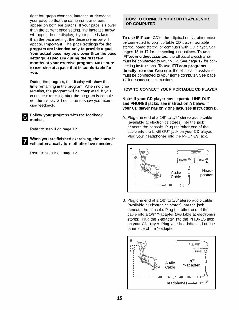
HOW TO CONNECT YOUR PORTABLE CD PLAYER
Note: If your CD player has separate LINE OUTand PHONES jacks, see instruction A below. Ifyour CD player has only one jack, see instruction B.
A. Plug one end of a 1/8” to 1/8” stereo audio cable(available at electronics stores) into the jackbeneath the console. Plug the other end of thecable into the LINE OUT jack on your CD player.Plug your headphones into the PHONES jack.
B. Plug one end of a 1/8” to 1/8” stereo audio cable(available at electronics stores) into the jackbeneath the console. Plug the other end of thecable into a 1/8” Y-adapter (available at electronicsstores). Plug the Y-adapter into the PHONES jackon your CD player. Plug your headphones into theother side of the Y-adapter.
7
6
LINE OUT
PHONES LINE OUT
PHONES
AudioCable
Head-phones
A
PHONES
PHONES
AudioCable
1/8” Y-adapter
Headphones
B
16
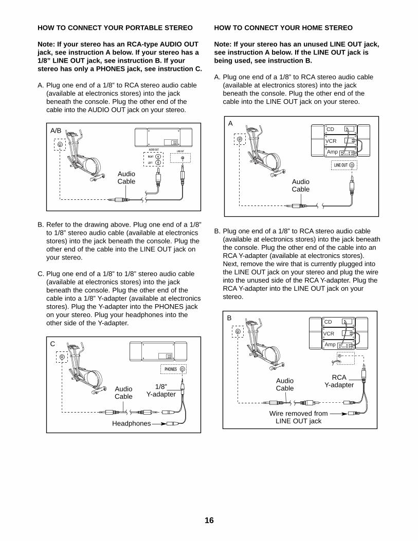
HOW TO CONNECT YOUR PORTABLE STEREO
Note: If your stereo has an RCA-type AUDIO OUTjack, see instruction A below. If your stereo has a1/8” LINE OUT jack, see instruction B. If yourstereo has only a PHONES jack, see instruction C.
A. Plug one end of a 1/8” to RCA stereo audio cable(available at electronics stores) into the jackbeneath the console. Plug the other end of thecable into the AUDIO OUT jack on your stereo.
B. Refer to the drawing above. Plug one end of a 1/8”to 1/8” stereo audio cable (available at electronicsstores) into the jack beneath the console. Plug theother end of the cable into the LINE OUT jack onyour stereo.
C. Plug one end of a 1/8” to 1/8” stereo audio cable(available at electronics stores) into the jackbeneath the console. Plug the other end of thecable into a 1/8” Y-adapter (available at electronicsstores). Plug the Y-adapter into the PHONES jackon your stereo. Plug your headphones into theother side of the Y-adapter.
HOW TO CONNECT YOUR HOME STEREO
Note: If your stereo has an unused LINE OUT jack,see instruction A below. If the LINE OUT jack isbeing used, see instruction B.
A. Plug one end of a 1/8” to RCA stereo audio cable(available at electronics stores) into the jackbeneath the console. Plug the other end of thecable into the LINE OUT jack on your stereo.
B. Plug one end of a 1/8” to RCA stereo audio cable(available at electronics stores) into the jack beneaththe console. Plug the other end of the cable into anRCA Y-adapter (available at electronics stores).Next, remove the wire that is currently plugged intothe LINE OUT jack on your stereo and plug the wireinto the unused side of the RCA Y-adapter. Plug theRCA Y-adapter into the LINE OUT jack on yourstereo.
AUDIO OUT
RIGHT
LEFT
LINE OUT
AudioCable
A/B
PHONES
AudioCable
C
1/8” Y-adapter
Headphones
CD
VCR
AmpLINE OUT
LINE OUT
AudioCable
A
CD
VCR
AmpLINE OUT
AudioCable
RCAY-adapter
Wire removed fromLINE OUT jack
B
17
HOW TO CONNECT YOUR COMPUTER
Note: If your computer has a 1/8” LINE OUT jack,see instruction A. If your computer has only aPHONES jack, see instruction B.
A. Plug one end of a 1/8” to 1/8” stereo audio cable(available at electronics stores) into the jackbeneath the console. Plug the other end of thecable into the LINE OUT jack on your computer.
B. Plug one end of a 1/8” to 1/8” stereo audio cable(available at electronics stores) into the jackbeneath the console. Plug the other end of thecable into a 1/8” Y-adapter (available at electronicsstores). Plug the Y-adapter into the PHONES jackon your computer. Plug your headphones or speak-ers into the other side of the Y-adapter.
HOW TO CONNECT YOUR VCR
Note: If your VCR has an unused AUDIO OUT jack,see instruction A below. If the AUDIO OUT jack isbeing used, see instruction B. If you have a TVwith a built-in VCR, see instruction B. If your VCRis connected to your home stereo, see HOW TOCONNECT YOUR HOME STEREO on page 16.
A. Plug one end of a 1/8” to RCA stereo audio cable(available at electronics stores) into the jackbeneath the console. Plug the other end of thecable into the AUDIO OUT jack on your VCR.
B. Plug one end of a 1/8” to RCA stereo audio cable(available at electronics stores) into the jackbeneath the console. Plug the other end of thecable into an RCA Y-adapter (available at electron-ics stores). Next, remove the wire that is currentlyplugged into the AUDIO OUT jack on your VCRand plug the wire into the unused side of the Y-adapter. Plug the Y-adapter into the AUDIO OUTjack on your VCR.
LINE OUT
AudioCable
A
PHONES
AudioCable
B
1/8” Y-adapter
Headphones/Speakers
AUDIO OUT
RIGHT
LEFT
VIDEO AUDIO
ANT. IN
RF OUTIN
OUT
CH3 4
AudioCable
A
VIDEO AUDIO
ANT. IN
RF OUTIN
OUT
CH3 4
Audio Cable
B
Wire removed fromAUDIO OUT jack
RCAY-adapter
18
To use iFIT.com CD’s or videocassettes, the ellipticalcrosstrainer must be connected to your portable CDplayer, portable stereo, home stereo, computer withCD player, or VCR. See HOW TO CONNECT YOURCD PLAYER, VCR, OR COMPUTER on page 15.Note: For information about the availability ofiFIT.com CD’s or videocassettes, send an e-mail [email protected], and we’ll notify youas soon as iFIT.com CD’s and videocassettes areavailable. Or, call toll-free 1-800-884-0620.
Follow the steps below to use an iFIT.com CD orvideo program.
Turn on the console.
Refer to step 1 on page 12.
Select the iFIT.com mode.
Each time theconsole isturned on, themanual modewill be selected.To select theiFIT.com mode,press theiFIT.com button. The indicator on the button willlight and the letters IF will appear in the upperright corner of the display.
Insert the iFIT.com CD or videocassette.
If you are using an iFIT.com CD, insert the CDinto your CD player. If you are using an iFIT.comvideocassette, insert the videocassette into yourVCR.
Press the play button on your CD player orVCR.
A moment after the play button is pressed, yourpersonal trainer will begin guiding you throughyour workout. Simply follow your personal trainer’sinstructions.
The program will function in almost the same wayas a Smart program (refer to step 3 on page 13).However, an electronic “chirping” sound will alertyou when the resistance and/or the pace setting isabout to change.
Note: If the resistance of the ellipticalcrosstrainer and/or the pace setting does notchange when a “chirp” is heard:
• Make sure that the indicator on the iFIT.combutton is lit.
• Adjust the volume of your CD player or VCR.If the volume is too high or too low, the con-sole may not detect the program signals.
• Make sure that the audio cable is properlyconnected and that it is fully plugged in.
Follow your progress with the feedback modes.
Refer to step 4 on page 12.
Measure your heart rate if desired.
Refer to step 5 on page 12.
When you are finished exercising, the consolewill automatically turn off after five minutes.
Refer to step 6 on page 12.
7
6
5
4
3
2
1
HOW TO USE IFIT.COM CD AND VIDEOPROGRAMS
19
HOW TO USE PROGRAMS DIRECTLY FROM OUR WEB SITE
Our Web site at www.iFIT.com allows you to playiFIT.com audio and video programs directly from theinternet. To use programs from our Web site, the ellip-tical crosstrainer must be connected to your homecomputer. See HOW TO CONNECT YOUR COMPUT-ER on page 17. In addition, you must have an internetconnection and an internet service provider. A list ofspecific system requirements will be found on our Website.
Follow the steps below to use a program from our Web site.
Turn on the console.
Refer to step 1 on page 12.
Select the iFIT.com mode.
Each time theconsole isturned on, themanual modewill be selected.To select theiFIT.com mode,press theiFIT.com button. The indicator on the button willlight and the letters IF will appear in the upperright corner of the display.
Go to your computer and start an internetconnection.
Start your Web browser, if necessary, and goto our Web site at www.iFIT.com.
Follow the desired links on our Web site toselect a program.
Read and follow the on-line instructions for usinga program.
Follow the on-line instructions to start theprogram.
When you start the program, an on-screen count-down will begin.
Return to the elliptical crosstrainer and beginexercising.
When the on-screen countdown ends, the pro-gram will begin. The program will function inalmost the same way as a Smart program (refer tostep 3 on page 13). However, an electronic “chirp-ing” sound will alert you when the resistanceand/or the pace setting is about to change.
Follow your progress with the feedback modes.
Refer to step 4 on page 12.
Measure your heart rate if desired.
Refer to step 5 on page 12.
When you are finished exercising, the consolewill automatically turn off after five minutes.
Refer to step 6 on page 12.
10
9
8
7
6
5
4
3
2
1
20
Inspect and tighten all parts of the elliptical crosstrainerregularly. Replace any worn parts immediately.
To clean the elliptical crosstrainer, use a damp clothand a small amount of mild dish soap. Important: Toavoid damage to the console, keep liquids awayfrom the console and keep the console out ofdirect sunlight.
BATTERY REPLACEMENT
If the console display becomes dim, the batteriesshould be replaced; most console problems are theresult of low batteries. Refer to assembly step 5 onpage 7 for replacement instructions. The consolerequires four “D” batteries.
HOW TO LEVEL THE ELLIPTICAL CROSSTRAINER
After the ellipticalcrosstrainer hasbeen moved tothe locationwhere it will beused, make surethat the ends ofboth stabilizersare touching thefloor. If the ellipti-cal crosstrainerrocks slightly during use, turn one or both of the level-ing feet under the front stabilizer until the rockingmotion is eliminated.
HANDGRIP PULSE SENSOR TROUBLE-SHOOTING
• Avoid moving your hands while using the handgrippulse sensor. Excessive movement may interferewith heart rate readings.
• Do not hold the metal contacts too tightly; doing somay interfere with heart rate readings.
• For the most accurate heart rate reading, hold themetal contacts for about 15 seconds.
• For optimal performance of the handgrip pulse sen-sor, keep the metal contacts clean. The contactscan be cleaned with a soft cloth—never use alcohol, abrasives, or chemicals.
HOW TO MOVE THE ELLIPTICAL CROSSTRAINER
Stand in front ofthe ellipticalcrosstrainer, holdthe handlebarsfirmly, and tip theelliptical cross-trainer until itcan be movedon the frontwheels. Carefullymove the ellipti-cal crosstrainer to the desired location and then lowerit. Due to the size and weight of the ellipticalcrosstrainer, use extreme caution while moving it.
MAINTENANCE AND TROUBLESHOOTING
Wheel
Leveling Foot
THE OPTIONAL CHEST PULSE SENSOR
The optional chest pulse sensor provides hands-freeoperation and continuously monitors your heart rateduring your workouts. To purchase the optionalchest pulse sensor, call toll-free 1-800-999-3756.
21
CONDITIONING GUIDELINES
The following guidelines will help you to plan yourexercise program. Remember that proper nutritionand adequate rest are essential for successful results.
EXERCISE INTENSITY
Whether your goal is to burn fat or to strengthen yourcardiovascular system, the key to achieving thedesired results is to exercise with the proper intensity.The proper intensity level can be found by using yourheart rate as a guide. The chart below shows recom-mended heart rates for fat burning, maximum fatburning, and cardiovascular (aerobic) exercise.
To find the proper heart rate for you, first find your ageon the bottom line of the chart (ages are rounded offto the nearest ten years). Next, find the three numbersabove your age. The three numbers are your “trainingzone.” The lower two numbers are recommendedheart rates for fat burning; the highest number is therecommended heart rate for aerobic exercise.
Fat Burning
To burn fat effectively, you must exercise at a relative-ly low intensity level for a sustained period of time.During the first few minutes of exercise, your body
uses easily accessible carbohydrate calories for ener-gy. Only after the first few minutes of exercise doesyour body begin to use stored fat calories for energy.If your goal is to burn fat, adjust the intensity of yourexercise until your heart rate is near the lowest num-ber in your training zone as you exercise.
For maximum fat burning, adjust the intensity of yourexercise until your heart rate is near the middle num-ber in your training zone as you exercise.
Aerobic Exercise
If your goal is to strengthen your cardiovascular sys-tem, your exercise must be “aerobic.” Aerobic exer-cise is activity that requires large amounts of oxygenfor prolonged periods of time. This increases thedemand on the heart to pump blood to the muscles,and on the lungs to oxygenate the blood. For aerobicexercise, adjust the intensity of your exercise untilyour heart rate is near the highest number in yourtraining zone as you exercise.
WORKOUT GUIDELINES
Each workout should include the following three parts:
A warm-up, consisting of 5 to 10 minutes of stretchingand light exercise. A proper warm-up increases yourbody temperature, heart rate, and circulation in prepa-ration for exercise.
Training zone exercise, consisting of 20 to 30 min-utes of exercising with your heart rate in your trainingzone. (During the first few weeks of your exercise program, do not keep your heart rate in your trainingzone for longer than 20 minutes.)
A cool-down, with 5 to 10 minutes of stretching. Thiswill increase the flexibility of your muscles and willhelp to prevent post-exercise problems.
EXERCISE FREQUENCY
To maintain or improve your condition, complete threeworkouts each week, with at least one day of restbetween workouts. After a few months of regular exer-cise, you may complete up to five workouts each weekif desired. The key to success is to make exercise aregular and enjoyable part of your everyday life.
WARNING:Before beginning this or any exercise pro-gram, consult your physician. This is espe-cially important for persons over the age of 35or persons with pre-existing health problems.
The pulse sensor is not a medical device.Various factors may affect the accuracy ofheart rate readings. The pulse sensor isintended only as an exercise aid in determin-ing heart rate trends in general.
22
Note: # indicates a non-illustrated part. Specifications are subject to change without notice.
1 1 Frame2 1 Upright3 1 Front Stabilizer4 1 Rear Stabilizer5 1 Console6 1 Left Side Shield7 1 Right Side Shield8 2 Cover Disc9 1 Left Handlebar10 1 Right Handlebar11 2 Foam Grip12 1 Right Pedal13 1 Left Pedal14 2 Flex Bar15 2 Adjustment Knob16 1 Left Flex Bracket17 2 Front Flex Bracket18 4 Rear Flex Bushing19 12 M6 x 33.5mm Bolt20 2 Adjustment Bolt21 4 Snap Ring22 2 M8 x 19mm Button Screw23 2 Handlebar Cap24 4 Handlebar Bushing25 2 Handlebar Spacer26 2 Upright Spacer27 2 M10 x 78mm Button Bolt28 4 Front Flex Bushing29 6 M10 Nylon Locknut30 1 Upright Bushing31 1 Left Front Endcap32 2 Wheel33 2 M6 x 72mm Wheel Bolt34 4 M10 x 112mm Carriage Bolt35 2 Rear Stabilizer Endcap36 2 Crank Arm37 2 Pulley38 6 M10 Zinc Washer39 1 Crank40 2 Crank Bearing41 1 Flywheel42 2 Flywheel Bearing43 1 Magnet44 1 Flywheel Axle45 6 M8.5mm Washer46 4 M8 Nylon Locknut47 2 Crank Screw
48 1 Idler Arm49 1 “J” Bolt50 1 M10 x 25mm Flat Screw51 2 Idler Bearing52 1 Idler Wheel53 3 M10.3 Black Washer54 1 “C” Magnet55 1 Motor56 1 Belt57 4 M8 x 33mm Button Screw58 4 M8 x 22mm Button Screw59 1 M6 x 38mm Stop Bolt60 3 M6 Nut61 4 M5 Nylon Locknut62 4 M5 x 12mm Bolt63 1 M10 x 88mm Button Bolt64 2 M4 x 6mm Screw65 8 M5 x 33mm Screw66 11 M4 x 16mm Screw67 4 M4 x 25mm Screw68 1 Right Front Endcap69 1 Reed Switch Clamp70 4 M10 Split Washer71 3 M10 x 27mm Screw72 2 Adjustment Foot73 1 M5 x 16mm Screw74 1 “U” Bracket75 1 M6 Eye Bolt76 1 Spring77 1 Reed Switch78 1 Reed Switch Bracket79 2 Flex Arm Spacer80 1 Side Shield Cover81 1 Handgrip Pulse Sensor82 1 Right Flex Bracket83 1 Frame Spacer84 4 M4 x 12mm Tap Screw85 2 M5 Nut86 1 Upper Wire Harness87 1 Lower Wire Harness88 2 M10 Zinc Nylon Locknut89 12 M6 Nylon Locknut90 12 M6 Split Washer# 1 Battery Cover# 1 Allen Wrench# 1 Grease# 1 User’s Manual
The model number and serial number of your PROFORM® 700CARDIO CROSSTRAINER are listed on a decal attached to theframe. See the front cover of this manual to find the location of thedecal.
All replacement parts are available for immediate purchase or special order when you visit your nearest SEARS Service Center.To request service or to order parts by telephone, call the toll-freenumbers listed at the left.
When requesting help or service, or ordering parts, please be pre-pared to provide the following information:
• The NAME OF THE PRODUCT (PROFORM® 700 CARDIOCROSSTRAINER)
• The MODEL NUMBER OF THE PRODUCT (831.285281)
• The KEY NUMBER OF THE PART (see page 14)
• The DESCRIPTION OF THE PART (see page 14).
Model No. 831.285281
QUESTIONS?If you find that:
• you need help assembling oroperating the PROFORM® 700
• a part is missing
• or you need to schedule repairservice
call our toll-free HELPLINE
1-800-736-6879Monday–Saturday, 7 am–7 pmCentral Time (excluding holidays)
REPLACEMENTPARTS
If parts become worn and need tobe replaced, call the followingtoll-free number
1-800-FON-PART (1-800-366-7278)
FULL 90 DAY WARRANTY
For 90 days from the date of purchase, if failure occurs due to defect in material or workmanship in thisSEARS ELLIPTICAL EXERCISER, contact the nearest SEARS Service Center throughout the UnitedStates and SEARS will repair or replace the ELLIPTICAL EXERCISER, free of charge.
This warranty does not apply when the ELLIPTICAL EXERCISER is used commercially or for rental purposes.
This warranty gives you specific legal rights, and you may also have other rights which vary from stateto state.
SEARS, ROEBUCK AND CO., DEPT. 817WA, HOFFMAN ESTATES, IL 60179