science for a changing world Borehole Dilatometer Installation, Operation, and Maintenance at sites in Hawaii By G.D.Myren, M.J.S. Johnston and R.J. Mueller Open File Report 2006-1103 U.S. Department of the Interior U.S. Geological Survey
Transcript
~USGSscience for a changing world
Borehole Dilatometer Installation, Operation, and
Maintenance at sites in Hawaii
By G.D.Myren, M.J.S. Johnston and R.J. Mueller
Open File Report 2006-1103
U.S. Department of the InteriorU.S. Geological Survey
u.s. Department of the InteriorDirk Kempthome, Secretary of Interior
u.s. Geological SurveyP. Patrick Leahy, Acting Director
u.s. Geological Survey, Reston, Virginia 2006Revised and reprinted: 2006
For product and ordering infonnation:World Wide Web: http://www.usgs.gov/pubprodTelephone: 1-888-ASK-USGS
For more infonnation on the USGS-the Federal source for science about the Earth,its natural and living resources, natural hazards, and the environment:World Wide Web: http://www.usgs.govTelephone: 1-888-ASK-USGS
Any use of trade, product, or [lIm names is for descriptive purposes only and does not implyendorsement by the u.s. Government.
Although this report is in the public domain, pennission must be secured from the individualcopyright owners to reproduce any copyrighted material contained within this report.
2
Contents
1. Introduction 5
2. Siting 5
3. Drilling 5
4. Dilatorneter Instrumentation 6
5. Dilatometer Installation 6
6. Additional Work and Installation 8
7. Electronics Enclosures 8
8. Surface Electronics 9
9. Basic Principle of Operation (SOC Box) 10
10. Valve opening algorithm 11
11. Cable & Connector Summary 12
12. Barometer 14
13. Telemetry 14
14. Dilatorneter Maintenance 14
15. Latitude & Longitude of Sites 15
16. Satellite Telemetry Configuration 15
Strip Rd 17Hokukano 31MaunaLoa 45Keller Well 59
ZENOSOFT 72Strip Rd 76Hokukano 77MaunaLoa 78Keller Well 79
17. Installation Field Notes 80
18. Drawings 81
3
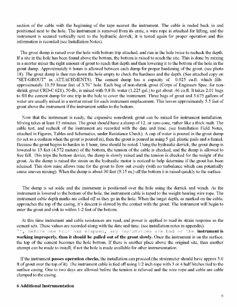
1 Introduction:
In response to concerns about the potential hazard of Mauna Loa volcano in Hawaii, the USGS began efforts in1998 to add four high-resolution borehole sites. Located at these sites are; strainrneters, tiltmeters, seismometers,accelerometers and other instrumentation. These instruments are capable of providing continuous monitoring ofthe magma movement under Mauna Loa. Each site was planned to provide multi-parameter monitoring ofvolcanic activity.
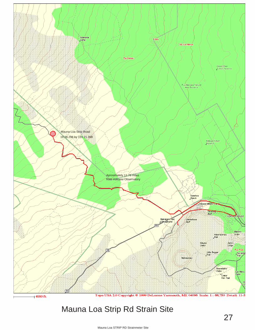
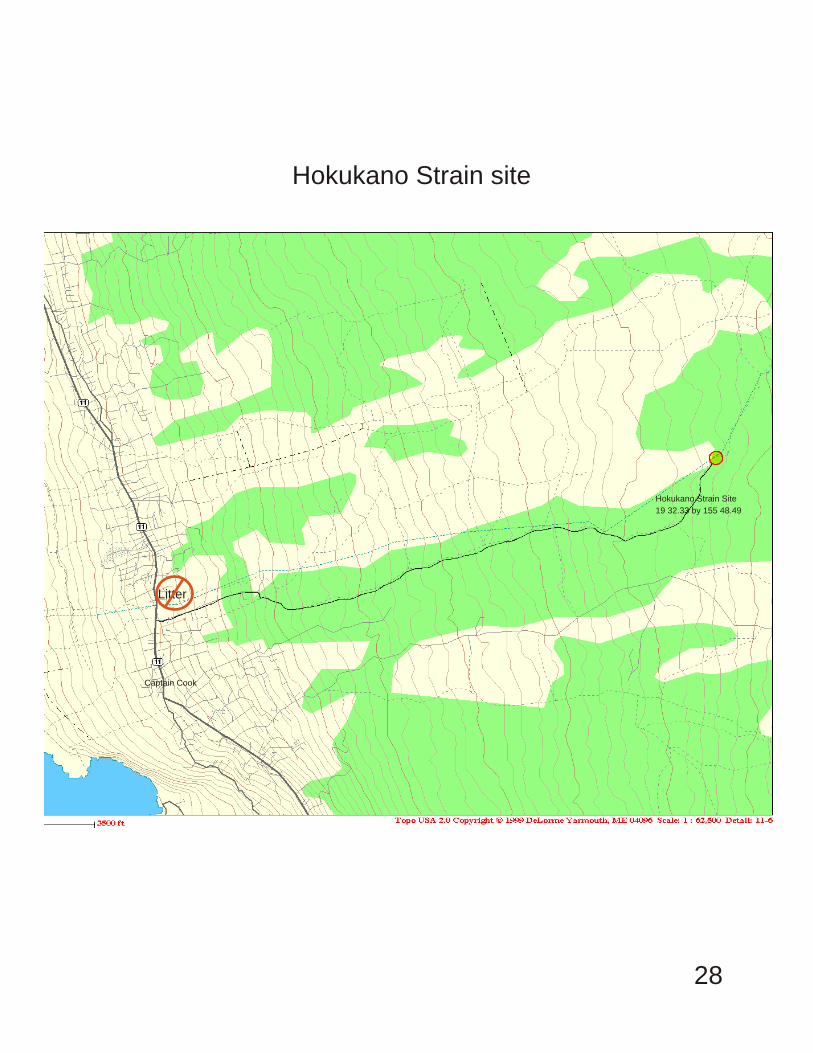
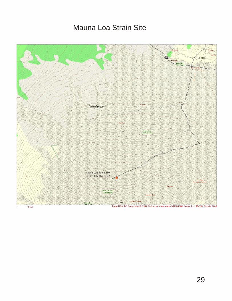
In June of2000, a contract was let for the core drilling of three ofthese four sites. They are located at Hokukano(west side of Mauna Loa) above Captain Cook, HI; at Mauna Loa Observatory (11,737' near the summit), and atMauna Loa Strip Road (east side of Mauna Loa). Another site was chosen near Halema'uma u' and Kilauea'ssummit, in the Keller deep well. (See maps). The locations of these instruments are shown in Figure 1 with theirlatitude and longitude in Table 1.
The purpose of this network is to monitor crustal deformation associated with volcanic intrusions andearthquakes on Mauna Loa and Kilauea volcanoes. This report describes the methods used to locate sites, installdilatometers, other instrumentation, and telemetry. We also provide a detailed description of the electronics usedfor signal amplification and telemetry, plus techniques used for instrument maintenance. Instrument sites wereselected in regions of hard volcanic rock where the expected signals from magmatic activity were calculated to bea maximum and the probability of earthquakes with magnitude 4 or greater is large. At each location, an attemptwas made to separate tectonic and volcanic signals from known noise sources for each instrument type.
2 Siting:Using seismicity, geologic and topographic maps together with geophysical knowledge and geologists
recommendations, a list of preliminary sites were selected. Available access, and telemetry issues were checkedout in detail during field visits. When the final site choice was made, permits were obtained from landowners anda drilling contract was drawn up to begin exploratory drilling.
3 Drilling:
The primary drilling method used, involved core drilling with a PQ (4.80"/12.192 cm old.) drill to deal with thetypical volcano geology in Hawaii. This geology consists of layered basaltic flows separated by ash deposits. Eachhole was core drilled to about 350 to 400 feet, allowing retrieval of 3.265" o.d. core. This continuous coreprovided scientist with an unprecedented look into the eruption history of Mauna Loa over the past 10,000 years.
When 3 m of competent unfractured rock was identified in the recovered core below 350 feet, that location wasrecorded as a possible installation site. After the best possibilities for installation sites were selected, the hole wascased with drill steel. Cementing of the casing was not successful due to the voids between flows. All holes werelocated well above the water table so all holes had to be drilled with air. Some holes were logged with a televiewerborehole inspection camera to help in selection of the best installation sites. Overall, this drilling method was theleast expensive for drilling in volcano geology. An inclinometer (measured the verticality of the holes) and acement bailer were run in each hole to check for clearance, and depth. When these parameters were alldetermined, the hole was deemed ready for installation.
4 DILATOMETER INSTRUMENTATION:
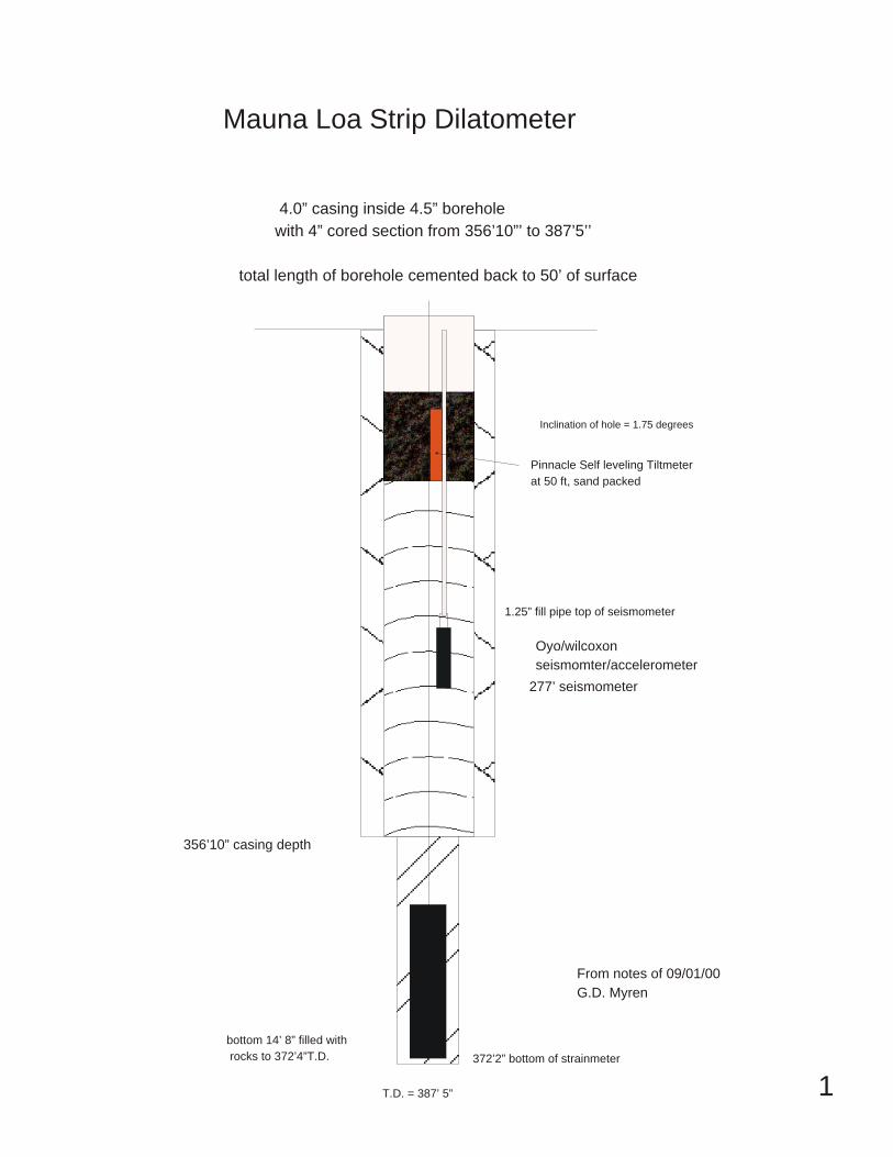
The Sacks-Evertson dilational strainrneter used in this experiment (Sacks \fIet allfR., 1971) are installed at
4
depths between 367' and 1192' below the surface on MaunaLoa and Kilauea. The sensors,installed as part of a cooperative program between the u.s. Geological Survey and the Carnegie Institution ofWashington, are cemented in the borehole with expansive grout having density characteristics approximatingthose of the host material. The borehole is then filled to the surface with cement to avoid long-term strains fromhole relaxation effects. (Re-equilibration ofthe aquifer system was not an issue at these dry volcanic boreholes.)
The sensor consists of a 3 m long stainless steel oil filled reservoir that is filled with 100 cs silicon oil. Smallcompressions on the side of this reservoir force oil into a small bellows. Displacement of the end of the bellows ismonitored by an LVDT (linear voltage displacement transducer) which produces an output that is proportional tothe imposed dilational strain. There are two LVDT's in the strainmeters installed in Hawaii. The first transducermeasures the rock strain, and the second transducer acts as reservoir volume monitor / 10 gain transducer /thermistor. The mechanical gain of the first LVDT is about 67,000. The frequency response is flat from about 20Hz to less than 0.000000001 Hz. The 20 Hz high frequency cut-off is caused by the hydraulic filter effect as theoil flows from the large reservoir into the bellows chamber through a small orifice.
5 DILATOMETER INSTALLATION
Introduction
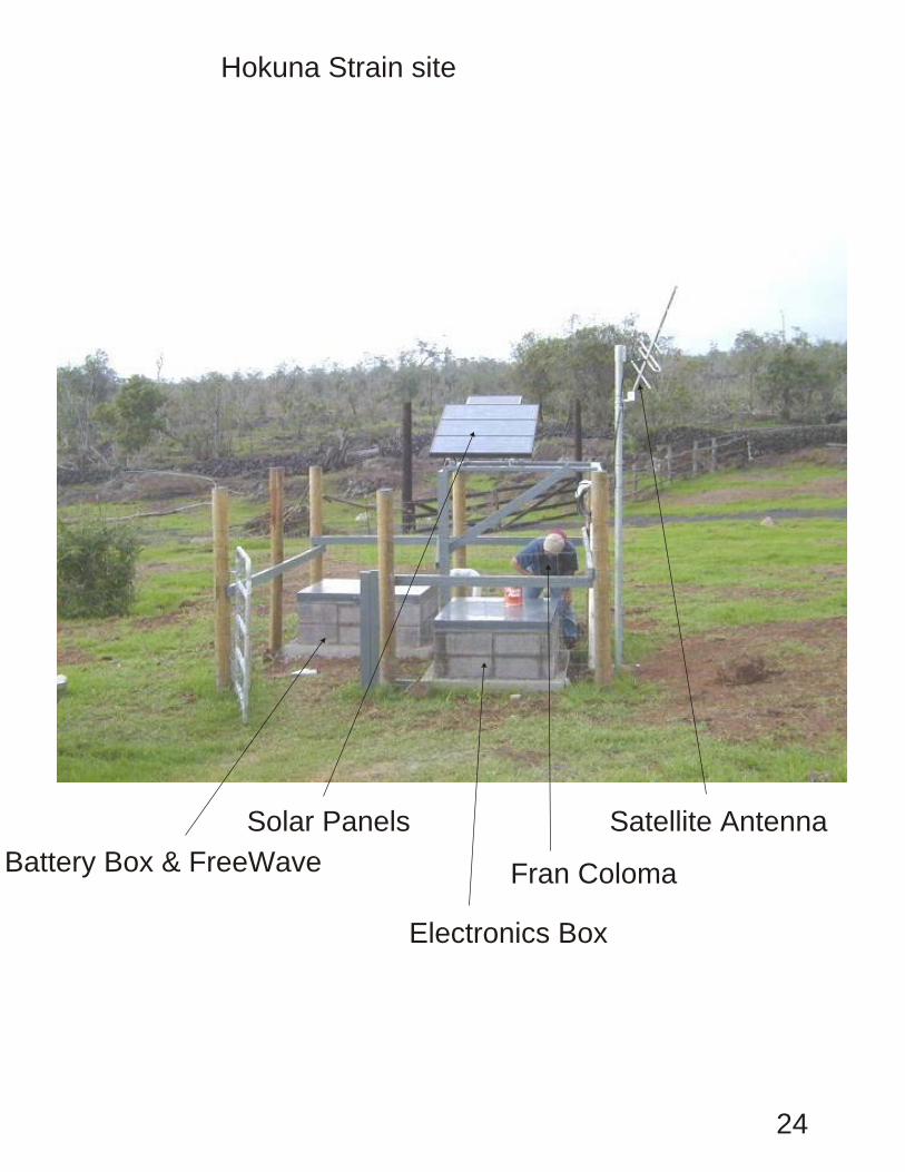
Installation was accomplished with the use of a truck mounted hydraulic winch and derrick. Before installation a28 foot (8.534 meters) long grout dump was lowered to the bottom of the hole to check that the instrument wouldnot get hung up during installation. Electronics for signal conditioning, amplification, data collection andtransmission are temperature tested in the lab and installed in closed bottom concrete block surface enclosures.The electronics are powered by solar charged batteries. They are located in similar concrete block surfaceenclosures within 15 feet (4.57 meters) ofthe electronics.
At these sites additional effort has been made to record the seismic portion of the signal generated by thedilatometer. This has been done using 24 bit recorders with Spread Spectrum radio telemetry to HVO. They areinstalled with solar charged batteries in a separate enclosure.
Installation ProcedureAfter a instrumentation site has been selected, the core hole has been drilled and competent rock has been
located below the casing, installation can begin.
A day before installation, the instrument is checked for correct operation and correct resistances between pinouts. Voltage is applied and readings of the signal out and signal change after the valve is closed and opened aretaken and recorded. (see Installation Notes in Figures, Tables and Schematics). The dilatometer is manufacturedwith additional ballast weight in the center section to help sink the instrument in the installation grout.
Prior to installation, a small hydraulic crane and winch is setup, its wire cable reeled out, measured and colorcoded every 50 feet(l5m.) for 1200 feet(365 m.). The grout dump, which is transported in three sections, isassembled. Its bottom opening trip mechanism is put together, greased, threaded to the bottom of the grout dump,and checked for operation.. The hydraulic derrick and winch are moved over the hole and the 27 foot (8.23 m.)grout dump is lowered to the bottom. When this clears, the bottom trip opens, and the hole depth agrees with thedepth determined by the drilling, the drill rig is allowed to leave the site.
The instrument cable (mounted on a cable reel stand in the back of a pick-up) is unreeled, measured and markedwith colored tape every 50 feet (IS m.). Twenty feet from the determined instrument depth a warning mark isattached. At the bottom depth mark for the instrument a bright colored tape is attached over a 2 foot (600 mm.)
5
section of the cable with the beginning of the tape nearest the instrument. The cable is reeled back in andpositioned next to the hole. The instrument is removed from its crate, a wire rope is attached for lifting, and theinstrument is secured vertically next to the hydraulic derrick, it is tested again for proper operation and thisinformation is recorded (see Installation Notes).
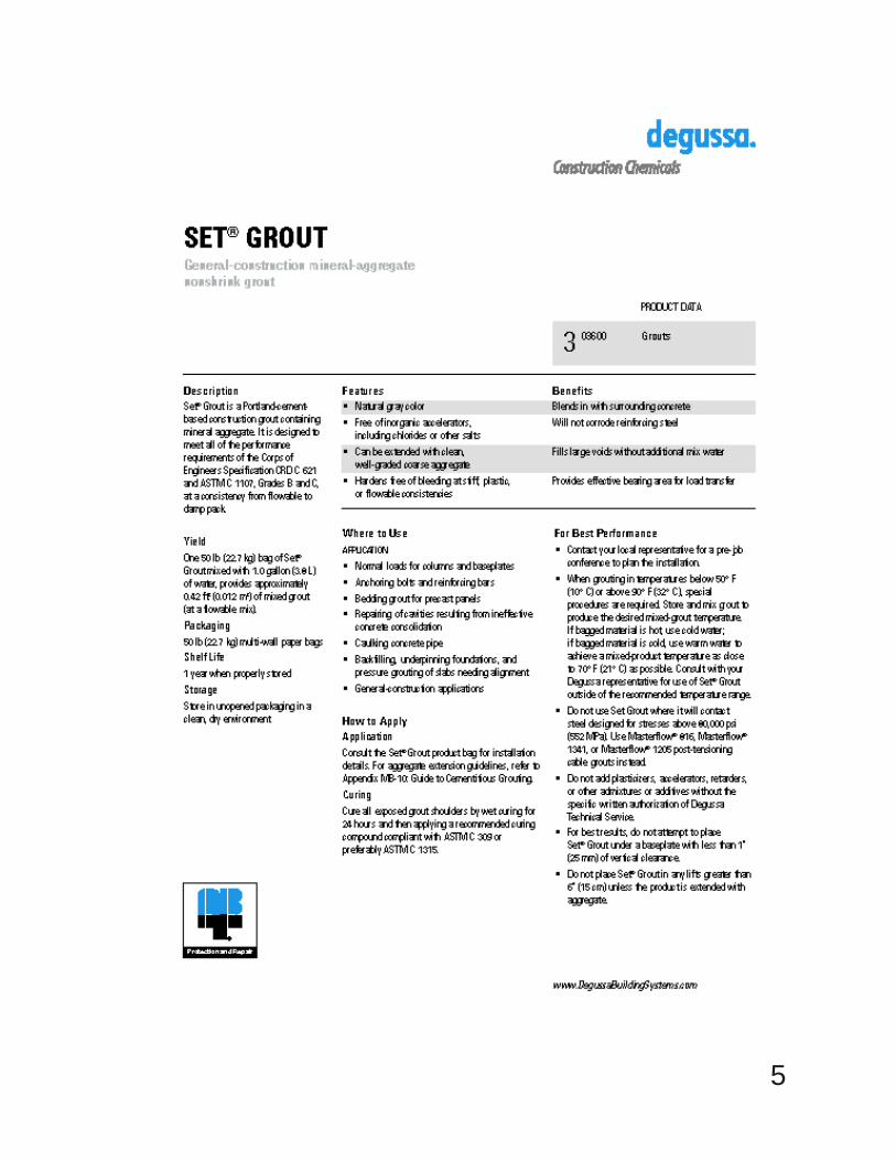
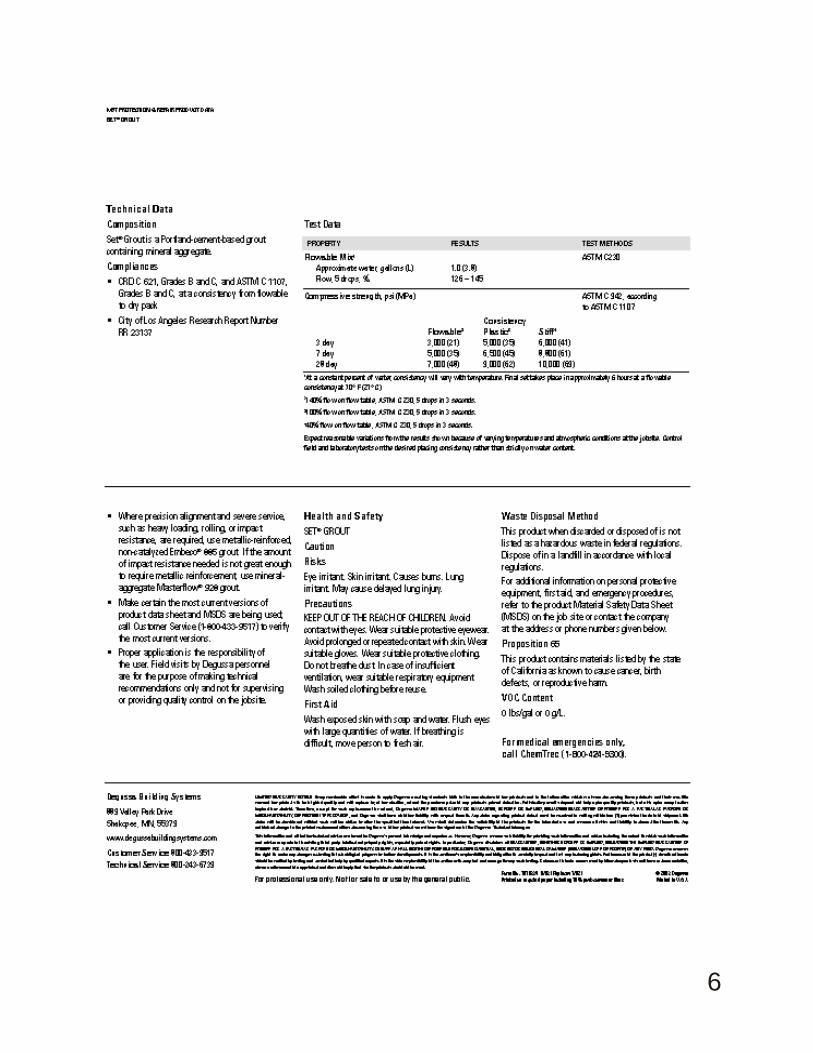
The grout dump is raised over the hole with bottom trip attached, and run in the hole twice to recheck the depth.If a site in the hole has been found above the bottom, the bottom is raised to reach the site. This is done by mixingin a mortar mixer the right amount of grout to reach that depth and then lowering it to the bottom ofthe hole in thegrout dump. Approximately 6 hours is allowed between each dump for proper hardening of the grout. (see photo18). The grout dump is then run down the hole empty to check the hardness and the depth. (See attached copy on"SET-GROUT" in ATTACHMENTS). The cement dump has a capacity of 0.925 cu.ft. which fillsapproximately 10.59 linear feet of 3.76" hole. Each bag of non-shrink grout (Corps of Engineers Spec. for nonshrink grout CRD-C 621), 50-lb., is mixed with 9.8 lb. water (1.225 gaL) to get about.46 cu.ft. It takes 2.01 bagsto fill the cement dump for one trip in the hole to cover the instrument. Three bags of grout and 3.675 gallons ofwater are usually mixed in a mortar mixer for each instrument emplacement. This leaves approximately 5.5 feet ofgrout above the instrument ifthe instrument settles to the bottom.
Now that the instrument is ready, the expansive non-shrink grout can be mixed for instrument installation.Mixing takes at least 15 minutes. The grout should have a slump of 12, or zero cone, rather like a thick malt. Thecable test, and recheck of the instrument are recorded with the date and time. (see Installation Field Notes,attached in Figures, Tables and Schematics, under Resistance Check). A cup ofwater is poured in the grout dump(to act as a cushion when the grout is poured in), then the grout is poured in using 5 gal. plastic pails and a funnel.Because the grout begins to harden in 1 hour, time should be noted. Using the hydraulic derrick, the grout dump islowered to 15 feet (4.572 meters) of the bottom, the tension of the cable is checked, and the dump is allowed tofree fall. This trips the bottom device, the dump is slowly raised and the tension is checked for the weight of thegrout. As the dump is raised the strain on the hydraulic motor is noticed to help determine if the grout has beenreleased. This slow raise allows time for the grout to flow out evenly (with no turbulence which can potentiallycause uneven mixing). When the dump is about 30 feet (9.15 m.) offthe bottom it is raised quickly to the surface.
The dump is set aside and the instrument is positioned over the hole using the derrick and winch. As theinstrument is lowered to the bottom of the hole, the instrument cable is taped to the weight bearing wire rope. Theinstrument cable depth marks are called off as they go in the hole. When the target depth, as marked on the cable,approaches the top of the casing, it's descent is slowed by the contact with the grout. The instrument will begin toenter the grout and sink to within 1-2 feet ofthe bottom.
At this time instrument and cable resistances are read, and power is applied to read its strain response as thecement sets. These values are recorded along with the date and time. (see installation notes in appendix).If, before one hour has elapsed, any resistances are bad or the instrumentisworking improperly, than it should be pulled out of the grout slowly. Once the instrument is on the surface,the top of the cement becomes the hole bottom. If there is another place above the original site, than anotherattempt can be made to install, ifnot the hole is made available for other instrumentation.
Ifthe instrument passes operation checks, the installation can proceed.(the strainmeter should have approx 5.0ft of grout over the top of it). The instrument cable is tied offusing 1/2 inch rope with 3 or 4 halfhitches tied to thesurface casing. One to two days are allowed before the tension is relieved and the wire rope and cable are cableclamped to the casing.
6 Additional Instrumentation
6
In order to optimize the science from these boreholes, additional cement is placed over the instrument and otherinstruments are installed. At Strip Rd, Hokukano, and Mauna Loa Observatory sites, boreholeseismometer/acceleration packages and tiltmeter instruments were installed.
At these sites the hole bottom was brought up to a point 100' above the top of the strainmeter by placing neatcement in the borehole. One inch flush joint tremmie pipe is lowered into the borehole in 20' sections by using thehydraulic derrick. Once this tremmie gently contacts the top of the strainmeter cement and the depth and volumeto a seismic package site is determined, a new bottom can be set. The tremmie is pulled back 20' and a neatcement mix is prepared and delivered by gravity through the tremmie to the new target depth. After the tremmie ispulled from the hole and washed, this mix is allowed to set overnight. The seismic/acceleration package is placedin the hole the next day using the same tremmie pipe It is cemented in place, and the hole bottom is brought upagain (using the same method of volume calculation & tremmie and cement placement) to 50 feet from thesurface. The tiltmeter can now be installed. It is attached to I" flush joint PVC tremmie pipe by a pvc press fitjoint with wire rope bearing the load.
7 ELECTRONICS ENCLOSURES
After the instruments are all installed and the hole is cemented to the surface, electronic surfaceenclosures are installed. These enclosures consist of a 3 ft. (0.9144 m.) wide, 4 ft. ( 1.2192 m.) long, by I Yz ft(0.4572 m.) high closed bottom concrete block structures with a steel lid for the electronics, and the same for thebatteries. The battery enclosure is a short distance from the electronics with solar panels for battery charging nearby. All enclosures are connected by pvc conduit for power and signal routing.
8 SURFACE ELECTRONICS
The electronics consists of signal amplifiers, a barometric pressure transducer, and two data collection systemshoused in the electronics enclosure. Electronics for signal conditioning, amplification, data collection andtransmission are temperature tested in the lab and installed in closed bottom concrete block surface enclosures.The electronics are powered by solar charged batteries. They are located in a closed bottom concrete block surfaceenclosures within 15 feet (4.57 meters) of the electronics. A water resistant box houses the electronics for thestrainmeter.
The strainmeter electronics consists of a dc/dc converter powering 2 op amps for 2 different DC (strain) signals,and a automatic valve opener driven by microprocessor control. The operation of the strainmeter electronics is afollows. As the strainmeter in the borehole is squeezed by the surrounding rock, silicon oil in the instrument isforced through an orifice, displaces a bellows, which moves the attached core of a transducer. The movement ofthis core is approximately .318V/.0 I in.(.318V/.254mm), as powered by a 6.8V voltage regulator. The movementofthis transducer is measured as a voltage at the surface in the SOC Box (Strainmeter Operation & Control Box).This voltage is monitored by a micro processor to control pressure relief of the transducer in the strainmeter. Asstated in the Dilatometer Instrumentation section, there are two LVDT's, one measures the strain on the rock, thesecond acts as a reservoir monitor/thermistor/lo gain transducer. The operation ofthe SOC Box is designed so thatif LVDT #1 exceeds a predetermined threshold voltage of 0.4 volts it's valve will open/close and pass thispressure to LVDT #2. After 2 hours LVDT #2's valve will open and pass this pressure in the form of fluid to thereservoir volume space ofthe strainmeter. (see appendix). If during the daily cycle of the instrument operation, thebattery powering the strainmeter should drop below 10 volts, the electronics will automatically shut down. It willopen both valves at this time preventing pressure from exceeding the physical limits of the LVDT's in theinstrument.
7
This electronics package draws approximately 380 milliamps. The electronics is powered by a 12 volt deepcycle maintenance free gelled electrolyte trickle charged battery. This battery is kept chargedby two 50 watt solar panels using a automatic sequencing charger. This charger stops charging at 14.3 volts +/-.2volts and resumes at 13.2 +/-0.3 volts. During the night a blocking diode acts to prevent discharge of the batterythrough the panel.
High frequency data from the dilatometer in the 0.005 Hz to 100 Hz can be recorded on 24 bit telemetrysystems with a least count noise of less thanl0 -11. Low frequency data, from 0 Hz to 0.002 Hz are transmittedvia a 17-bit digital telemetry system through the GOES satellite system to Menlo Park, Cal. A separate polledspread spectrum telemetry to USGS Hawaii Volcano Observatory provides 1 minute data. The least count noiseon the high gain satellite telemetry system for the dilatometer is about 2 * 10 -11. For the low gain channel theleast count noise is about 1.2 * 10 -8. These instruments all record earth strain tides, strain transients related tovolcanic deformation and numerous strain seismograms from local and tele-seismic earthquakes with magnitudesbetween 1 and 9. These strain seismograms are used to calculate the dynamic earthquake moments.
Static moments and total earthquake moments are determined from the co-seismic strains and total strainchanges observed with larger events. Should pre-seismic strains occur before an expected volcanic eruption, theycan be resolved at about the 10 to -11 level if they occur quickly, and about 10 to -8 level if they occur days toweeks before the event.
9. Basic Principle of Operation:Summary:SOC Box Operation (as described by Carnegie Institute of Washington / DTM) is as follows:
The strainmeter control box contains the electronics, which control and monitor the strainmeter. It also filters andpasses the analog signals from the strainmeter to an external device. The external device is usually an Analog-toDigital converter passing digital data to either local storage or a telemetry system or both.Detailed Description:Supply power to the strainmeter control box is monitored internally by the electronics to determine if sufficientvoltage is present at the input to the strainmeter control box. If the voltage dips below the preset trip voltage (should be about 1OVdc ), the controller will disconnect power until the voltage rises to an acceptable level. Thereis some hysteresis designed into the power monitoring circuitry to avoid the unwanted condition of power-off,power-on, power-off, etc... This on-off-on-off-on is something that could be quite common with a solar-cellcharged battery system if the hysteresis was not implemented. To avoid any problems that could arise fromsustained power cycling, hysteresis is used in the power monitoring circuit. Additionally supply power ismonitored by the microcontroller by way of analog input to the 16-bit multiplexing AID. If the voltage measuredby the AID drops to an unacceptable level the microcontroller will immediately open the strainmeter valves in aneffort to protect the strainmeter. If this precaution was not taken when power is sagging, the strainmeter controlbox might shut down with valves closed during a seismic event. This could easily rupture the bellows in thestrainmeter, leaving it unusable.The strainmeter control box supplies power to the Differential Transformers contained in the strainmeter. Thecontrol box will supply a regulated 6.8VDC potential to the DT power inputThe Valves in the strainmeters (designed and manufactured at the Carnegie Institution of Washington) open orclose depending on the polarity of the potential voltage applied to the valves. Most of the older land-basedstrainmeters operate with a valve operating potential of 24VDC. The newer land- and water-based strainmeters
8
have valves that operate at 48VDC'. The serial connection is optically isolated using the RS-232 standard. It usesthe following parameters.BAUD: 9600, DATA BITS: 8, STOP BITS: I, PARITY: NoneAs of the writing of this manual the Dept. of Terrestrial Magnetism has adopted a policy to use only 48VDCvalves on all future water- and land-based strainmeters.
High Threshold Voltage:3.0Volts (60% of AID's maximum voltage level)
Valve behavior ifDT1 voltage exceeds low threshold for 15 consecutive minutes:Valve I opensValve 2 is scheduled to open 2 hours later.Valve I closes IS seconds after opening.Valve 2 closes IS seconds after opening.
Valve2 behavior ifDT2 voltage exceeds low threshold for 11 consecutive minutes:Valve 2 opens.Valve 2 closes IS seconds after opening.
Valve1 behavior ifDT1 voltage exceeds high threshold:Valve I opens.Valve I closes I minute afer openingValve 2 is scheduled to open 11 minutes after Valve I closes.Valve 2 remains open for 5 seconds.
If Valve I opens again in less than II minutes, Valve2 opening isrescheduled for II minutes following next Valve I closing.
Valve2 behavior ifDT2 voltage exceeds high threshold:Valve 2 opens.Valve 2 closes 5 SEC after opening.
Interlock:If Valve I needs to open we check ifValve2 is open. If Valv e2 is open, we close Valve 2 before opening Valve 1.
If Valve 2 needs to open we check if Valve I is open. If Valve I is open, we close Valve I before opening Valv e2
9
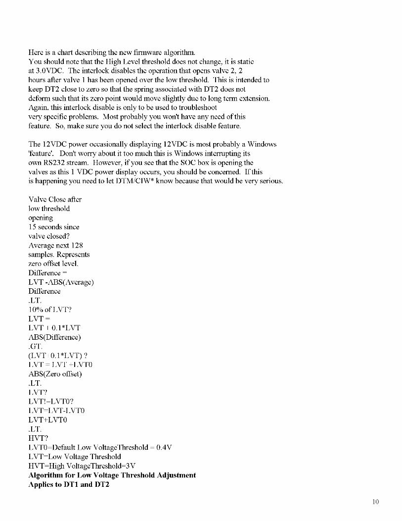
Here is a chart describing the new finnware algorithm.You should note that the High Level threshold does not change, it is staticat 3.0VDC. The interlock disables the operation that opens valve 2, 2hours after valve I has been opened over the low threshold. This is intended tokeep DT2 close to zero so that the spring associated with DT2 does notdefonn such that its zero point would move slightly due to long tenn extension.Again, this interlock disable is only to be used to troubleshootvery specific problems. Most probably you won't have any need ofthisfeature. So, make sure you do not select the interlock disable feature.
The 12VDC power occasionally displaying 12VDC is most probably a Windows'feature'. Don't worry about it too much this is Windows interrupting itsown RS232 stream. However, ifyou see that the SOC box is opening thevalves as this I VDC power display occurs, you should be concerned. Ifthisis happening you need to let DTM/CIW* know because that would be very serious.
Valve Close afterlow thresholdopemng15 seconds sincevalve closed?Average next 128samples. Representszero offset level.Difference ~
LVT+LVTO.LT.HVT?LVTO~Default Low VoltageThreshold ~ 0.4VLVT~Low Voltage ThresholdHVT~High VoltageThreshold~3V
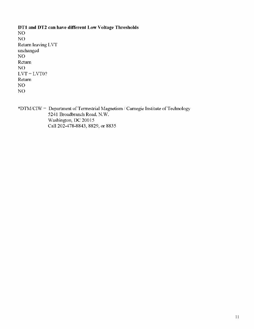
Algorithm for Low Voltage Threshold AdjustmentApplies to DTl and DT2
10
DTl and DT2 can have different Low Voltage ThresholdsNONOReturn leaving LVTunchangedNOReturnNOLVT ~ LVTO?ReturnNONO
*DTM/CIW ~ Department of Tenrestrial Magnetism / Carnegie Institute of Technology5241 Broadbranch Road, N.W.Washington, DC 20015Call 202-478-8843, 8829, or 8835
11
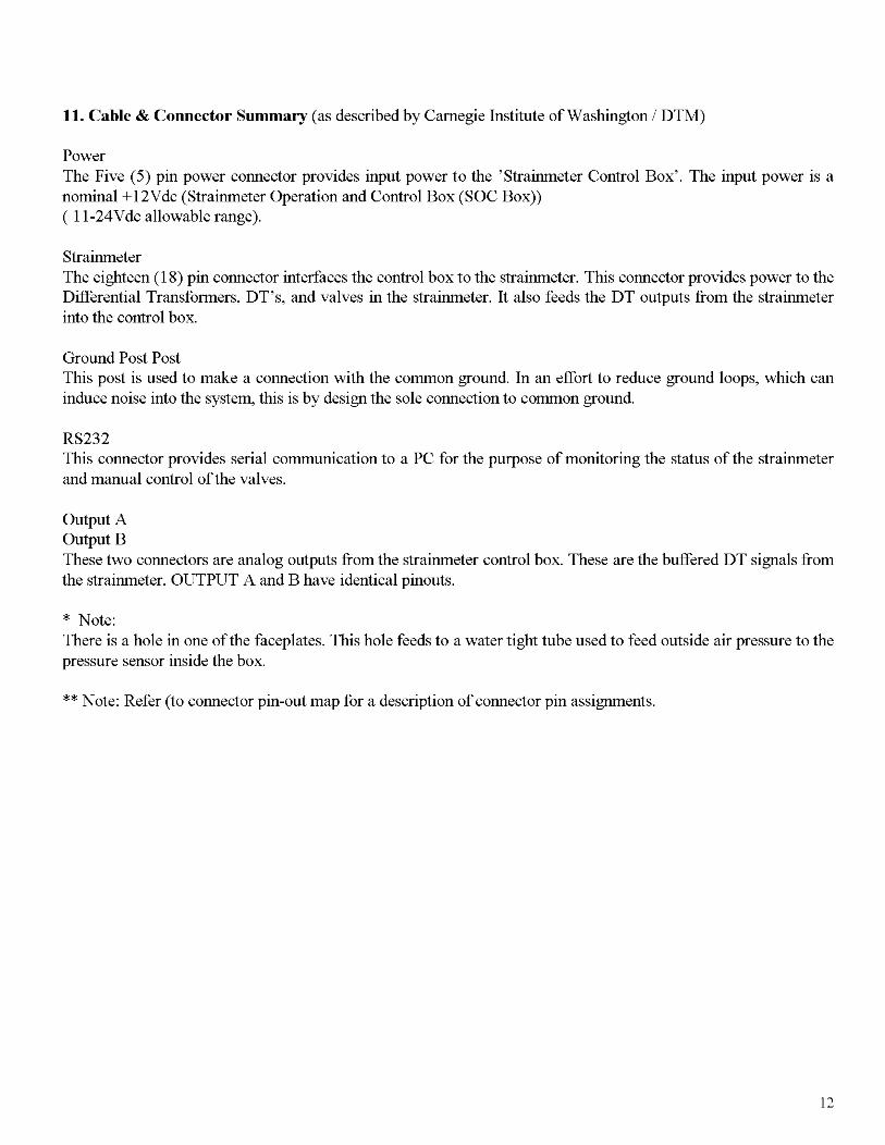
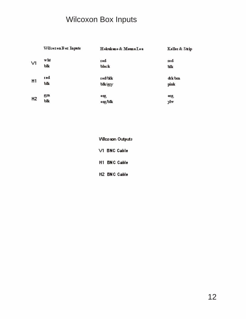
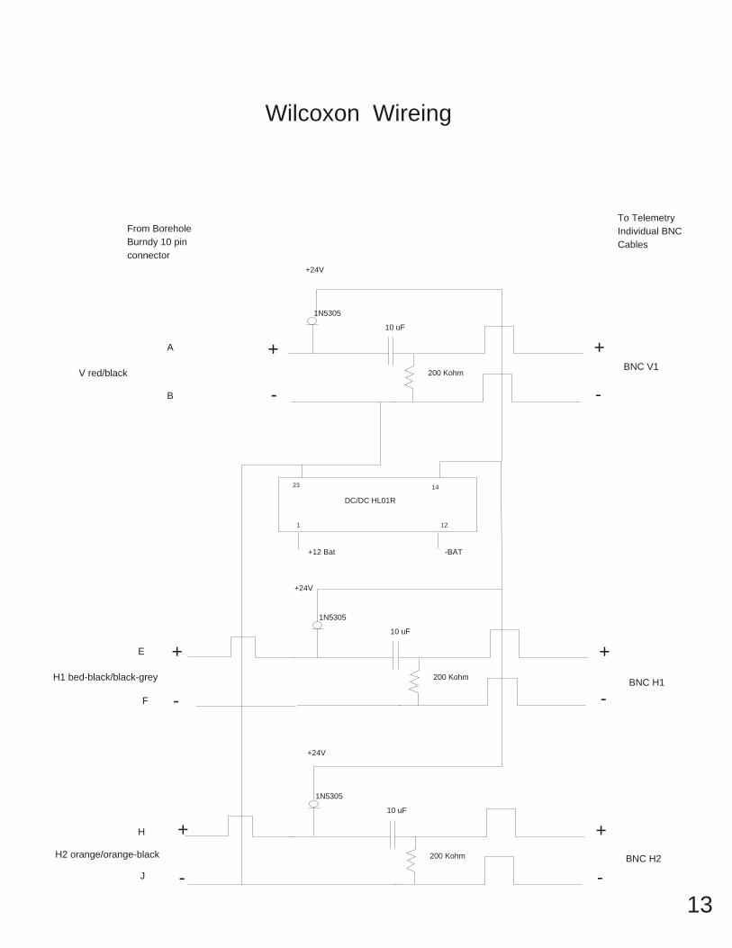
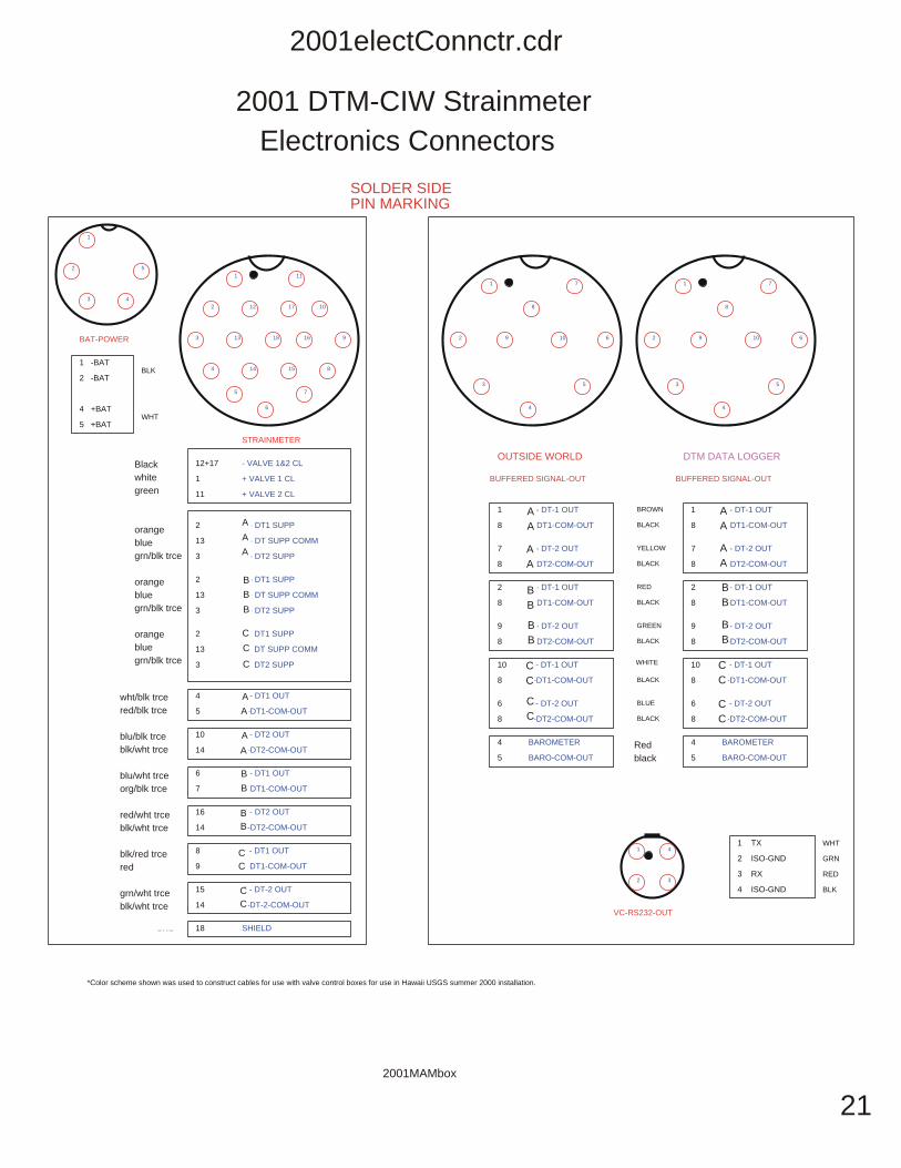
11. Cable & Connector Summary (as described by Carnegie Institute of Washington / DTM)
PowerThe Five (5) pin power connector provides input power to the 'Strainrneter Control Box'. The input power is anominal +12Vdc (Strainrneter Operation and Control Box (SOC Box))( 11-24Vdc allowable range).
StrainrneterThe eighteen (18) pin connector interfaces the control box to the strainrneter. This connector provides power to theDifferential Transformers, DT's, and valves in the strainrneter. It also feeds the DT outputs from the strainrneterinto the control box.
Ground Post PostThis post is used to make a connection with the common ground. In an effort to reduce ground loops, which caninduce noise into the system, this is by design the sole connection to common ground.
RS232This connector provides serial communication to a PC for the purpose of monitoring the status of the strainrneterand manual control ofthe valves.
Output AOutputBThese two connectors are analog outputs from the strainrneter control box. These are the buffered DT signals fromthe strainrneter. OUTPUT A and B have identical pinouts.
* Note:There is a hole in one ofthe faceplates. This hole feeds to a water tight tube used to feed outside air pressure to thepressure sensor inside the box.
** Note: Refer (to connector pin-out map for a description of connector pin assignments.
12
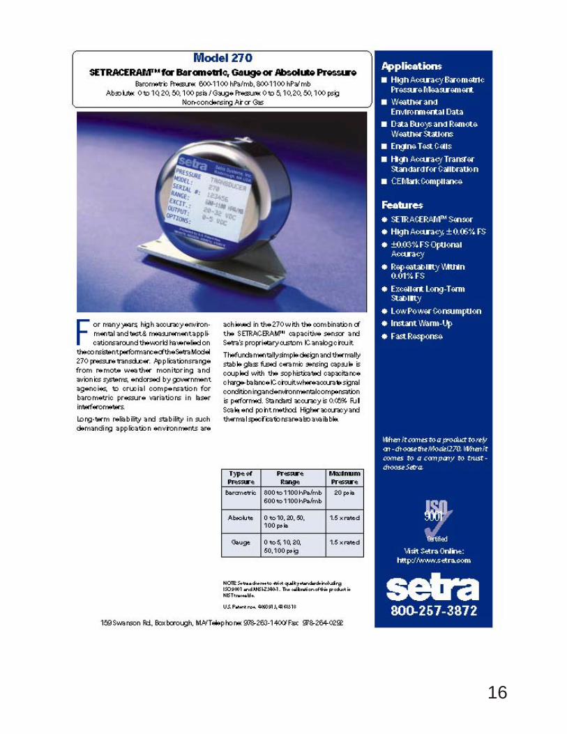
12. Barometer:There is a barometric pressure transducer operating over a 300 millibar range. This on site transducer aids in
the reduction of the strain data as it is effected by barometric pressure. (see barometric pressure transducer inAdditional Electronics Section.) Setra Model #270
The barometric pressure transducer is powered by 1 12 volt deep-cycle maintenance free gelled electrolyte tricklecharged batteries. This is kept charged by a similar automatic sequencing charger hooked to a 20 watt solar panel.
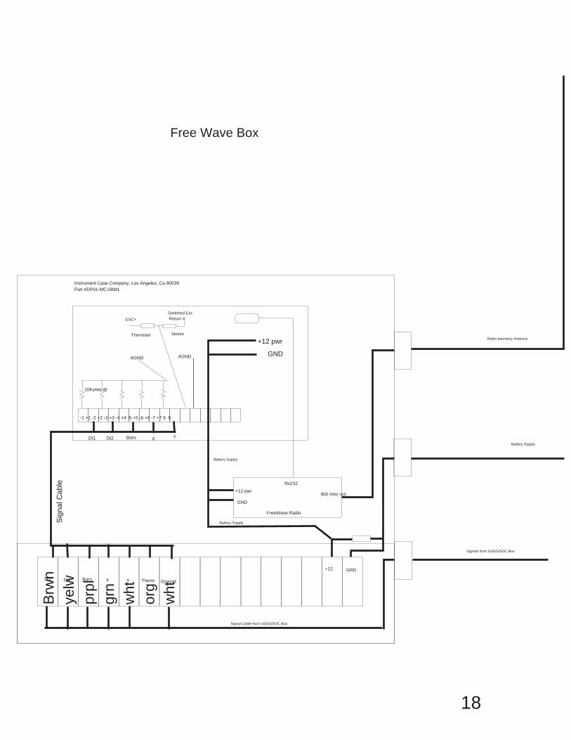
13 Telemetry:
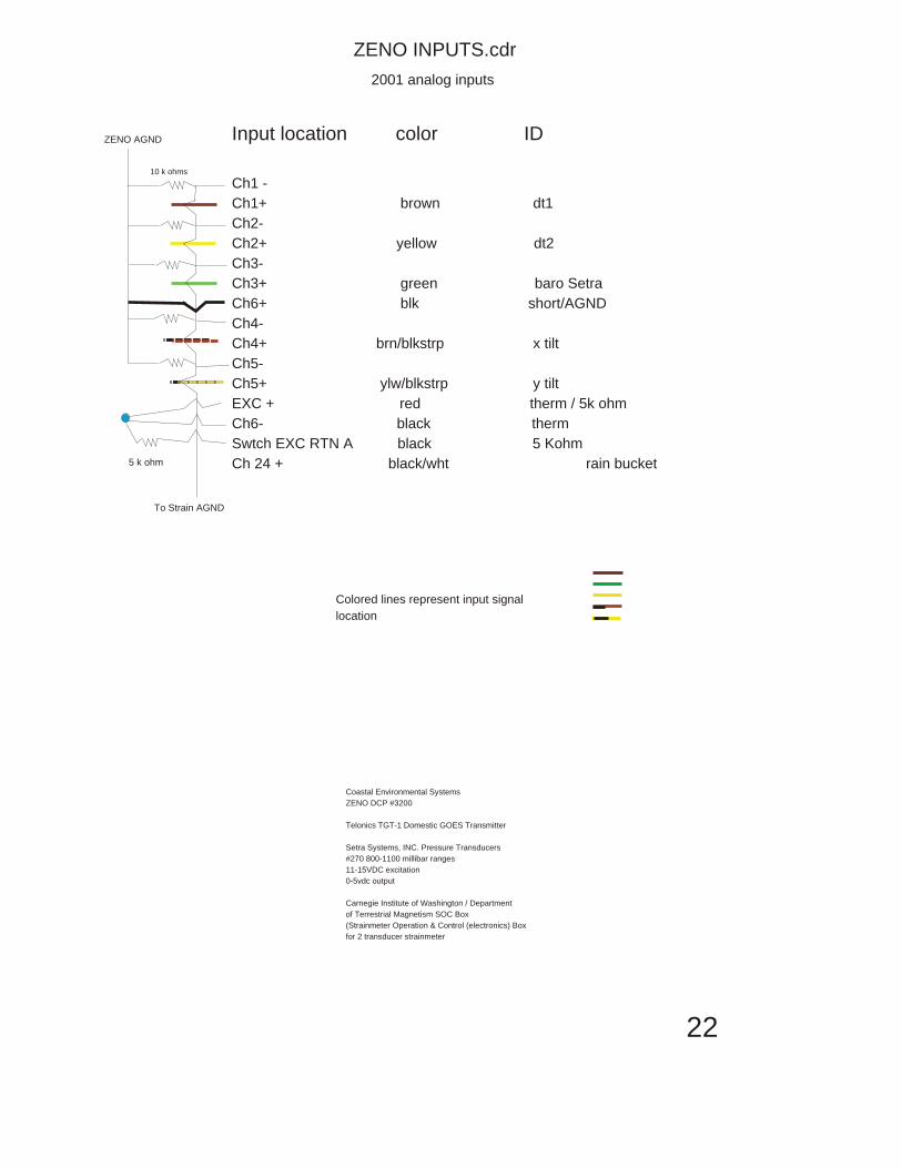
Coastal Environmental Systems ZENO Model 3200 was selected as a Data Collection Platform. This systemdraws 84ma at 12 volts DC during collection and 3 amps at transmission of data to the GOES satellite. Data iscollected once every 10 minutes to 17 bit accuracy and transmitted at 10 minute intervals. A second ZENO is alsoinstalled for transmission of 1 minute data via Spread Spectrum radio to the Hawaii Volcano Observatory. It alsouses a auto sequencing charger and a 50 watt solar panel to keep the battery charged.
14. PROCEDURE FOR DILATOMETER MAINTENANCE:
In general the maintenance of a dilatometer installation is fairly straightforward. There may be the specificinstance when a visit may be made for unexpected problems, but for the most part it is a routine procedure. Insummary, the data from each instrument is looked at daily for proper operation. It is inspected for tidal response(data quality), data dropouts (satellite problems, computer problems, missing transmisions), time of transmission,transmission power levels, and battery voltages. Information obtained from this helps in the proper fieldmaintenance.
13
15. Latitude and Longitude Locations
Site Abbreviation Latitude Longitude Elevation
Mauna Loa Strip Road STOI-09 19.46117 155.34940 5,071 ftHokukano HKOI - 09 19.53884 155.80814 4,764 ftMauna Loa Observatory MLOl- 09 19.53651 155.57478 11,131ftKeller Well KWOl- 09 19.39262 155.34940 3,622 ft
These are all strammeter sites. Installed with 2.75" o.d. by 10' longVolumetric Strainmeters. they have two transducers installed,#1 is the sensing volume, #2 is the reservoir recovery volume/thermister downhole.
16. Satellite Data Configuration
Strip Road Straimueterlat 19 28.29810ng 155 21.398Data Logger ~ Coastal Environmental Systems ZENO 3200 sn #?01 - 08 are +/-17 bit, 09 +/-12 bits101 ~ transducer #1 hi gain +/-.512 volt range 3.91xl0-6s102 ~" " 10 " +/-5.12 volt range 3.91xl0-5s103 ~" #210 " +/-5.12 volt range 3.91xl0-5s104 ~ input to AID as a short to ground +/-5.12 volt range 3.91xlO-5s105 ~ Setra #270 600-900mbar at 0 - 5vdc +/-5.12 volt range 3.91xl0-5s106 ~ tiltmeter x axis +/-5.12 volt range 3.91xl0-5
at 17meter depth gain 3 in tiltmeter ~ 95.60mv/microradianor 0.0004581574 microradians/ct
s107 ~ tiltmeter yaxis +/-5.12 volt range 3.91xl0-5at 17meter depth gain 3 in tiltmeter ~ 98.1 O/microradianor 0.00039819062 microradians/ct
s108 ~ YSI4401 thermister +/-5.12 volt range 3.91xl0-5C x .001 (ie, 15666 x .001 ~ +15.666)
s109 ~ +/- 12 bit range ~ .007816291 volts/ct (.007816291 by 1720 ~ 13.44 volts dc)stl 0 ~~ tipping bucket raingage, 1 count ~ ImillimeterNumber of assigned DCP bits 01 - 08 are +/-17 bit; 09 is +/-12 bit, 10 ~ rain gage
HolaUkIuno Straimueterlat 19 32.330 long 155 48.489Data Logger ~ Coastal Environmental Systems ZENO 3200 sn #?
Component description,sensor/digitizer gain,voltage range input to DCPhkOI ~transducer #1 hi gain +/-.512 volt range 3.91xl0-6hk02 ~" " 10 " +/-5.12 volt range 3.91xl0-5hk03 ~" #2 10 " +/-5.12 volt range 3.91xl0-5hk04 ~ input to AID as a short to ground +/-5.12 volt range 3.91xl0-5
14
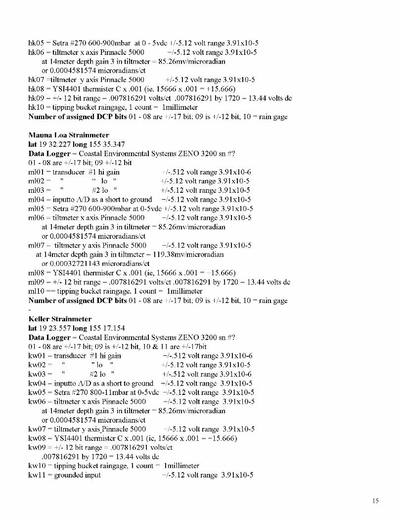
hk05 ~ Setra #270 600-900mbar at 0 - 5vdc +/-5.12 volt range 3.91x10⁻⁵hk06 ~ tiltmeter x axis Pinnacle 5000 +/-5.12 volt range 3.91x10⁻⁵
at 14meter depth gain 3 in tiltmeter ~ 85.26mv/microradianor 0.0004581574 microradians/ct
hk07 ~iltmeter y axis Pinnacle 5000 +/-5.12 volt range 3.91x10⁻⁵hk08 ~ YSI4401 thermister C x .001 (ie, 15666 x .001 ~ +15.666)hk09 ~ +/- 12 bit range ~ .007816291 volts/ct .007816291 by 1720 ~ 13.44 volts dchk1 0 ~ tipping bucket raingage, 1 count ~ 1millimeterNumber of assigned DCP bits 01 - 08 are +/-17 bit; 09 is +/-12 bit, 10 ~ rain gage
Mauna Loa Straiumeter1at 19 32.2271ong 155 35.347Data Logger ~ Coastal Environmental Systems ZENO 3200 sn #?01 - 08 are +/-17 bit; 09 +/-12 bitmlOl ~transducer #1 hi gain +/-.512 volt range 3.91x10⁻⁶m102 ~" " 10 " +/-5.12 volt range 3.91x10⁻⁵m103 ~" #210 " +/-5.12 volt range 3.91x10⁻⁵m104 ~ inputto AID as a short to ground +/-5.12 volt range 3.91x10⁻⁵m105 ~ Setra #270 600-900mbar at 0-5vdc +/-5.12 volt range 3.91x10⁻⁵m106 ~ tiltmeter x axis Pinnacle 5000 +/-5.12 volt range 3.91x10⁻⁵
at 14meter depth gain 3 in tiltmeter ~ 85.26mv/microradianor 0.0004581574 microradians/ct
m107 ~ tiltmetery axis Pinnacle 5000 +/-5.12 volt range 3.91x10⁻⁵at 14meter depth gain 3 in tiltmeter ~ 119.38mv/microradian
or 0.00032721143 microradians/ctm108 ~ YSI4401 thermister C x .001 (ie, 15666 x .001 ~ +15.666)m109 ~ +/- 12 bit range ~ .007816291 volts/ct .007816291 by 1720 ~ 13.44 volts dcmll 0 ~~ tipping bucket raingage, 1 count ~ 1millimeterNumber of assigned DCP bits 01 - 08 are +/-17 bit; 09 is +/-12 bit, 10 ~ rain gage
Keller Straiumeter1at 19 23.5571ong 15517.154Data Logger ~ Coastal Environmental Systems ZENO 3200 sn #?01 - 08 are +/-17 bit; 09 is +/-12 bit, 10 & 11 are +/-17bitkw01 ~transducer #1 hi gain +/-.512 volt range 3.91x10⁻⁶kw02 ~" "10" +/-5.12 volt range 3.91x10⁻⁵kw03 ~" #210 " +/-.512 volt range 3.91xlO-6kw04 ~ inputto AID as a short to ground +/-5.12 volt range 3.91x10⁻⁵kw05 ~ Setra #270 800-11mbar at 0-5vdc +/-5.12 volt range 3.91x10⁻⁵kw06 ~ tiltmeter x axis Pinnacle 5000 +/-5.12 volt range 3.91x10⁻⁵
at 14meter depth gain 3 in tiltmeter ~ 85.26mv/microradianor 0.0004581574 microradians/ct
kw07 ~tiltmeteryaxis_Pinnacle 5000 +/-5.12 volt range 3.91x10⁻⁵kw08 ~ YSI4401 thermister C x .001 (ie, 15666 x .001 ~ +15.666)kw09 ~ +/- 12 bit range ~ .007816291 volts/ct
.007816291 by 1720 ~ 13.44 volts dckw10 ~ tipping bucket raingage, 1 count ~ 1millimeterkw11 ~ grounded input +/-5.12 volt range 3.91x10⁻⁵
15
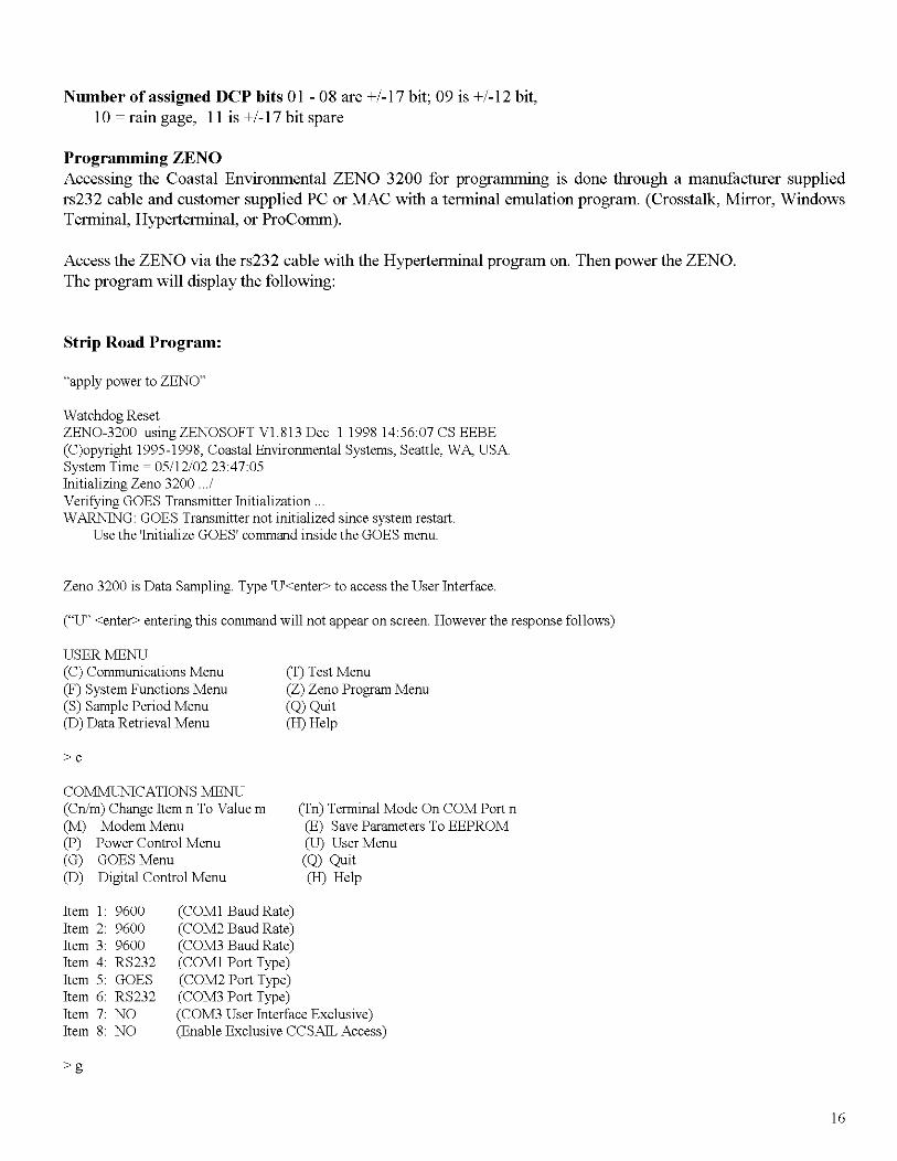
Number of assigned ncp bits 01 - 08 are +/-17 bit; 09 is +/-12 bit,10 ~ rain gage, II is +/-17 bit spare
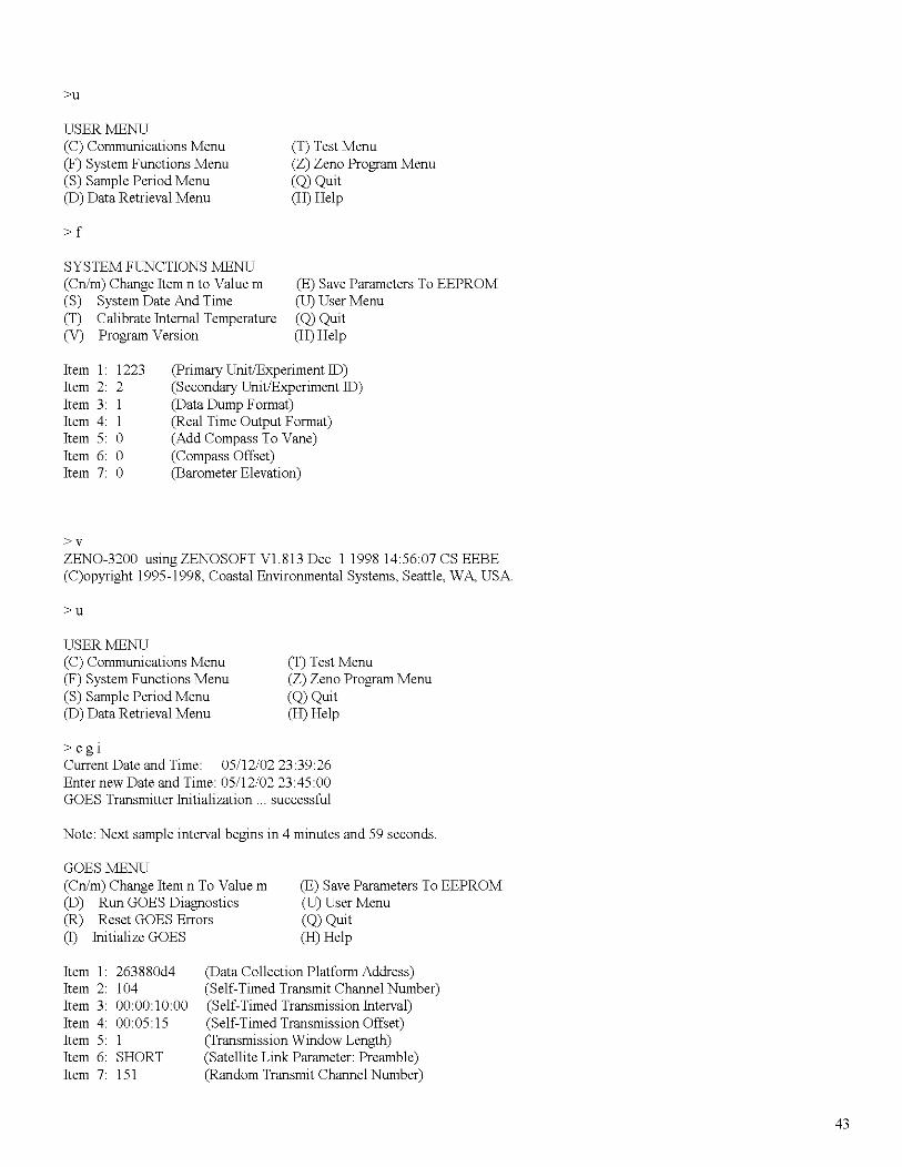
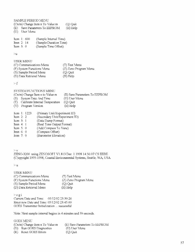
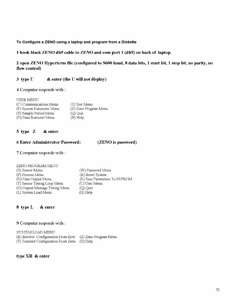
Progrannning ZENOAccessing the Coastal Environmental ZENO 3200 for progrannning is done through a manufacturer suppliedrs232 cable and customer supplied PC or MAC with a terminal emulation program. (Crosstalk, Mirror, WindowsTerminal, Hyperterminal, or ProConnn).
Access the ZENO via the rs232 cable with the Hyperterminal program on. Then power the ZENO.The program will display the following:
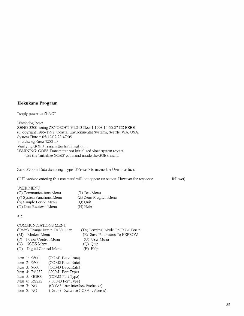
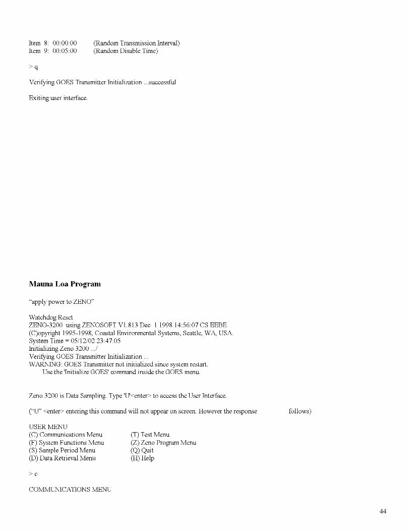
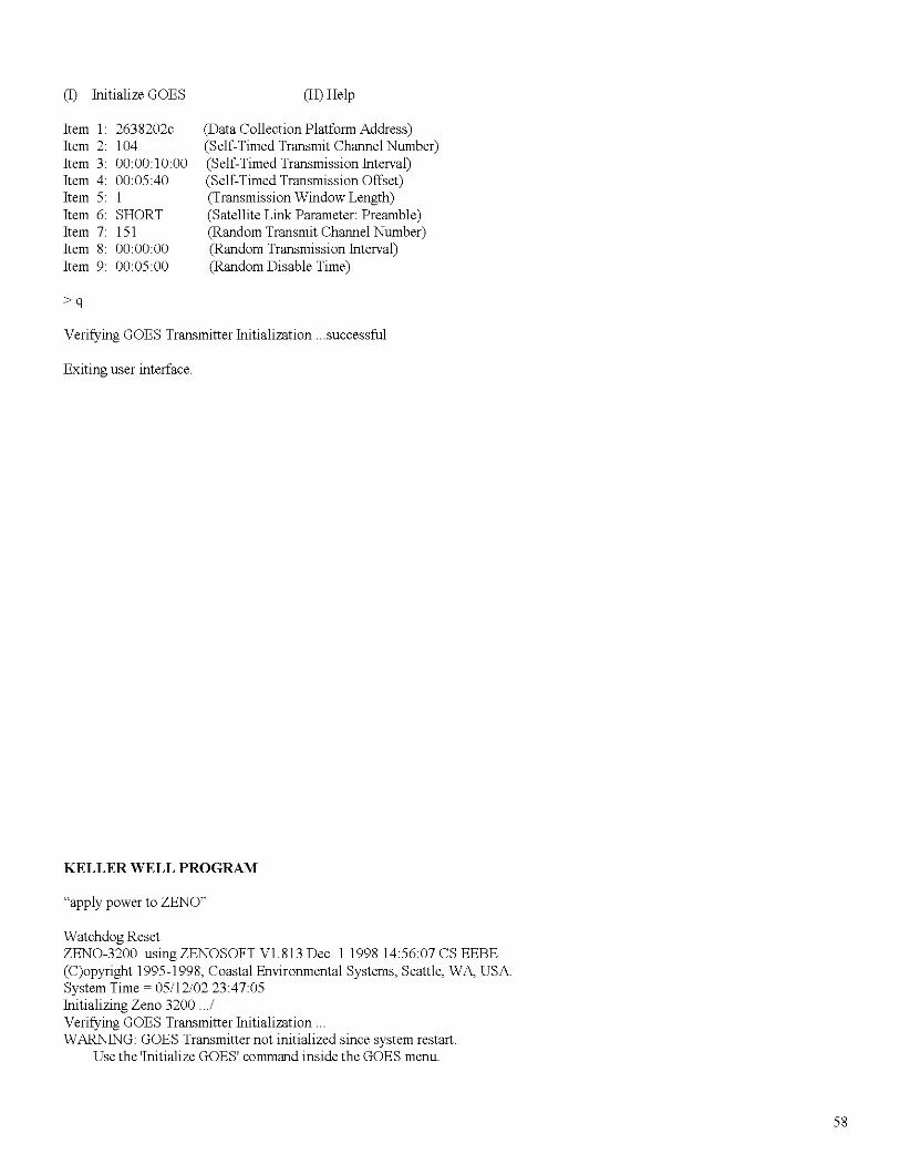
Strip Road Program:
"apply power to ZENO"
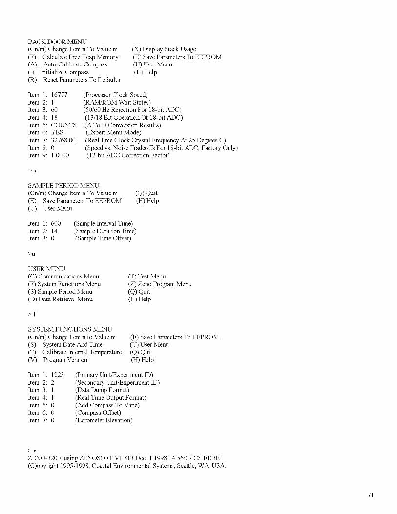
Watchdog ResetZENO-3200 using ZENOSOFT V1.813 Dec 1 1998 145607 CS EEBE(C)opyright 1995-1998, Coastal Environmental Systems, Seattle, WA, USASystem Time ~ 05/12/02 23:47:05Initializing Zeno 3200 .. JVerifying GOES Transmitter Initialization ..WARNINU: GOES Transmitter not initialized since system restart.
Use the 'Initialize GOES' command inside the GOES menu.
Zeno 3200 is Data Sampling. Type 'U<enter> to access the User Interface.
("u' <enter> entering this command will not appear on screen. However the response follows)
USER MENU(C) Communications Menu(F) System Functions Menu(S) Sample Period Menu(D) Data Retrieval Menu
>c
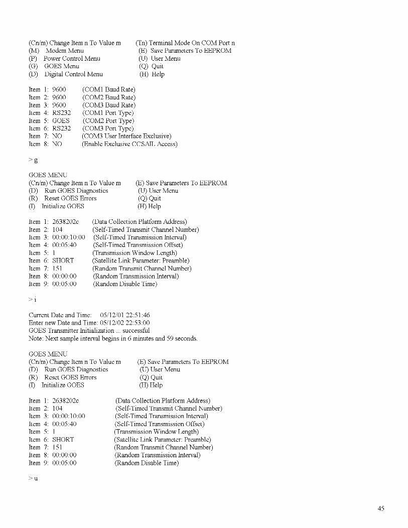
COMMUNICATIONS MENU(Cn/m) Change Item n To Value m(M) Modem Menu(P) Power Control Menu(G) GOES Menu(D) Digital Control Menu
(T) Test Menu(Z) Zeno Program Menu(Q) Quit(H) Help
(Tn) Terminal Mode On COM Port n(E) Save Parameters To EEPROM(U) User Menu(Q) Quit(H) Help
(COMI Baud Rate)(COM2 Baud Rate)(COM3 Baud Rate)(COMI Port Type)(COM2 Port Type)(COM3 Port Type)(COM3 User Interface Exclusive)(Enable Exclusive CCSAIL Access)
16
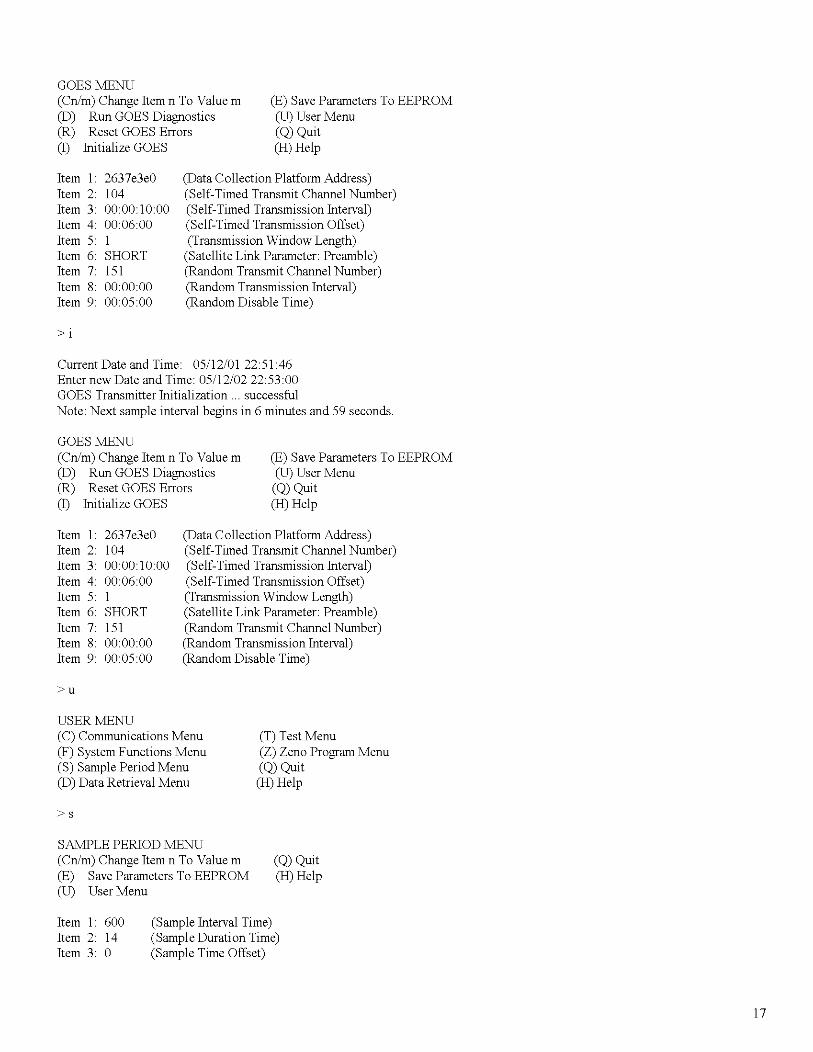
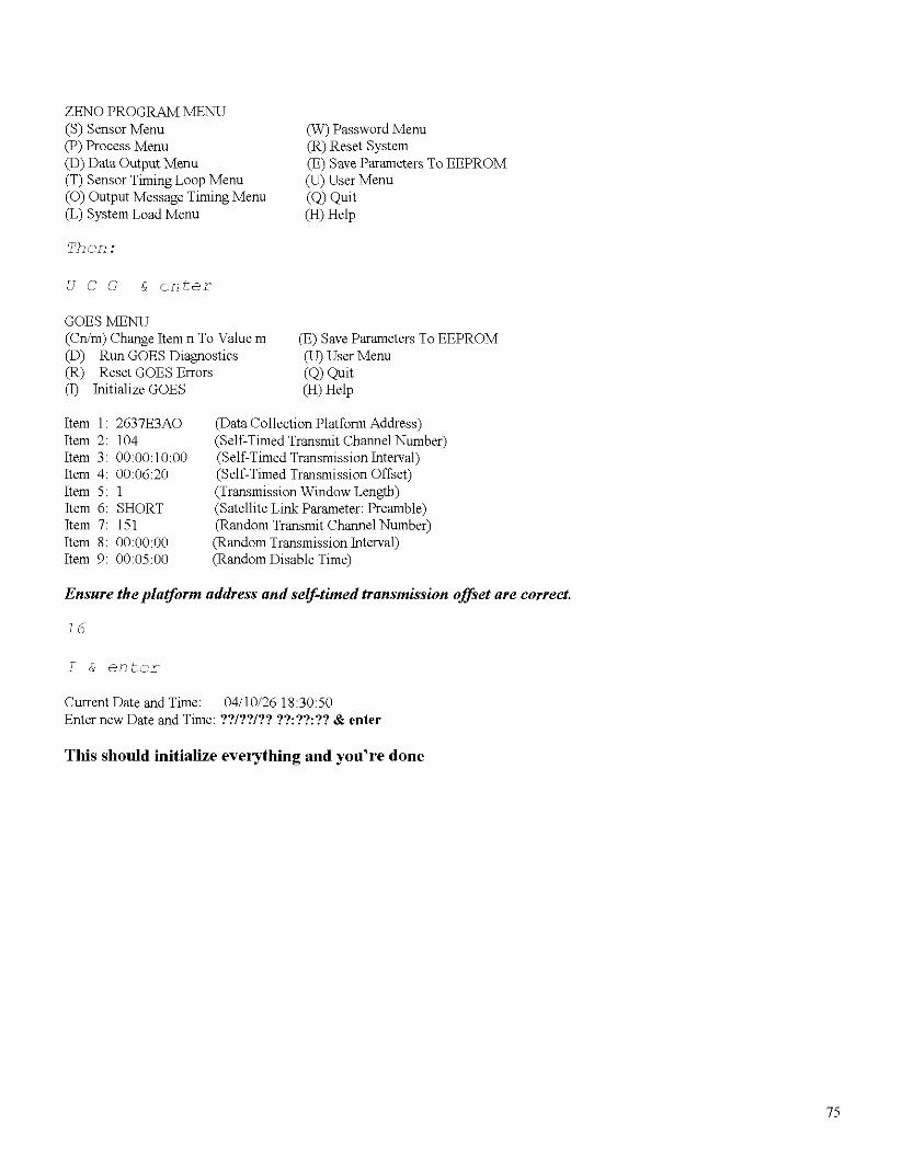
GOES MENU(Cn/m) Change Item n To Value m(D) Run GOES Diagnostics(R) Reset GOES Errors(I) Initialize GOES
(E) Save Parameters To EEPROM(U) User Menu(Q) Quit(H) Help
Current Date and Time: 05/12/01 22:51:46Enter new Date and Time: 05/12/0222:53:00GOES Transmitter Initialization ... successfulNote: Next sample interval begins in 6 minutes and 59 seconds.
GOES MENU(Cn/m) Change Item n To Value m(D) Run GOES Diagnostics(R) Reset GOES Errors(I) Initialize GOES
USER MENU(C) Communications Menu(F) System Functions Menu(S) Sample Period Menu(D) Data Retrieval Menu
>s
SAMPLE PERIOD MENU(Cn/m) Change Item n To Value m(E) Save Parameters To EEPROM(U) User Menu
(T) Test Menu(Z) Zeno Program Menu(Q) Quit(H) Help
(Q) Quit(H) Help
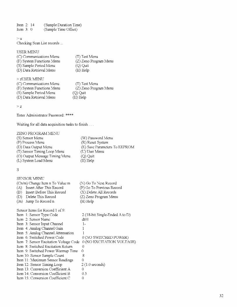
Item 1: 600Item 2: 14Item 3: 0
(Sample Interval Time)(Sample Duration Time)(Sample Time Offset)
17
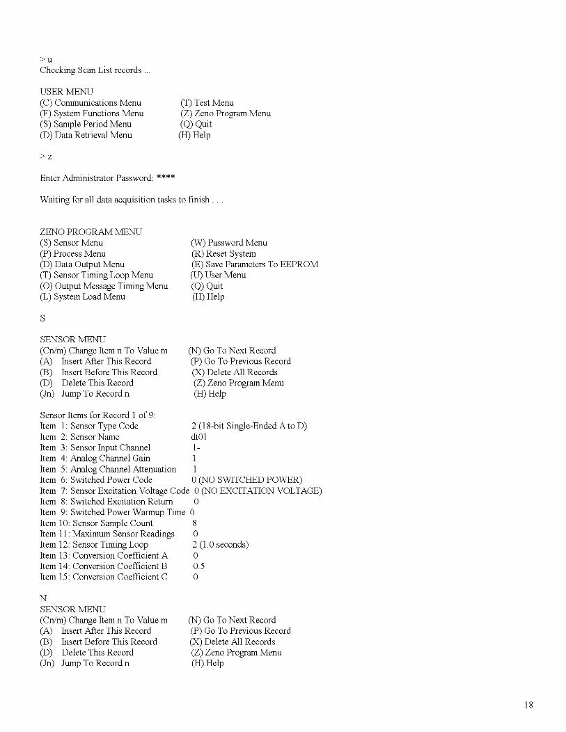
>uChecking Scan List records.
USER MENU(C) Communications Menu(F) System Functions Menu(S) Sample Period Menu(D) Data Retrieval Menu
>z
Enter Administrator Password: ****
(T) Test Menu(Z) Zeno Program Menu(Q) Quit(H) Help
Waiting for all data acquisition tasks to finish.
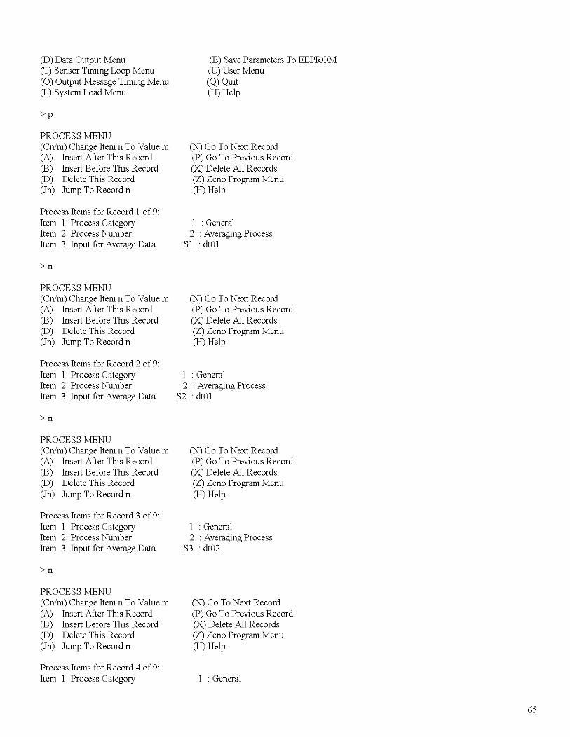
ZENO PROGRAM MENU(S) Sensor Menu(P) Process Menu(D) Data Output Menu(T) Sensor Timing Loop Menu(0) Output Message Timing Menu(L) System Load Menu
S
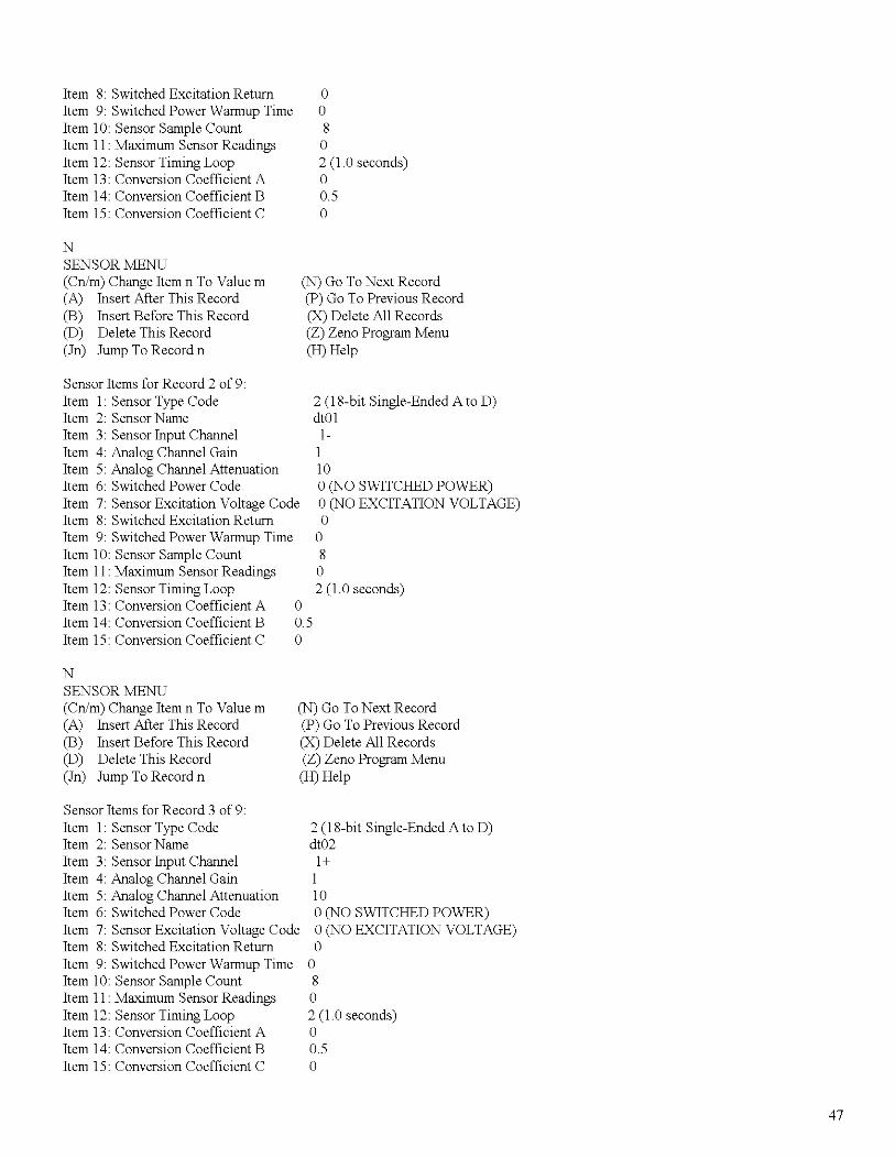
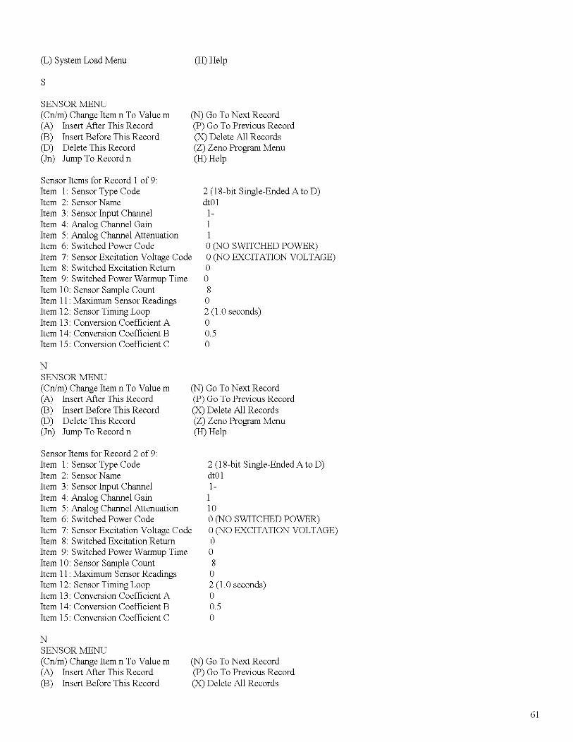
SENSOR MENU(Cn/m) Change Item n To Value m(A) Insert After This Record(B) Insert Before This Record(D) Delete This Record(In) Jump To Record n
(W) Password Menu(R) Reset System(E) Save Parameters To EEPROM(U) User Menu(Q) Quit(H) Help
(N) Go ToNext Record(P) Go To Previous Record(X) Delete All Records(Z) Zeno Program Menu(H) Help
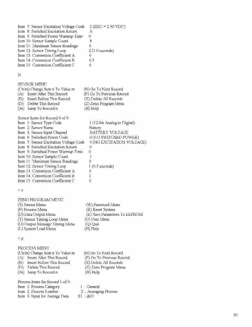
Sensor Items for Record 1 of 9:Item 1: Sensor Type Code 2 (l8-bit Single-Ended A to D)Item 2: Sensor Name dlO1Item 3: Sensor Input Channel l-Item 4: Analog Channel Gain 1Item 5: Analog Channel Attenuation 1Item 6: Switched Power Code a(NO SWITCHED POWER)Item 7: Sensor Excitation Voltage Code a(NO EXCITATION VOLTAGE)Item 8: Switched Excitation Return aItem 9: Switched Power Warmup Time aItem 10: Sensor Sample Count 8Item 11: Maximum Sensor Readings aItem 12: Sensor Timing Loop 2 (1.0 seconds)Item 13: Conversion Coefficient A aItem 14: Conversion Coefficient B 0.5Item 15: Conversion Coefficient C a
NSENSOR MENU(Cn/m) Change Item n To Value m(A) Insert After This Record(B) Insert Before This Record(D) Delete This Record(In) Jump To Record n
(N) Go ToNext Record(P) Go To Previous Record(X) Delete All Records(Z) Zeno Program Menu(H) Help
18
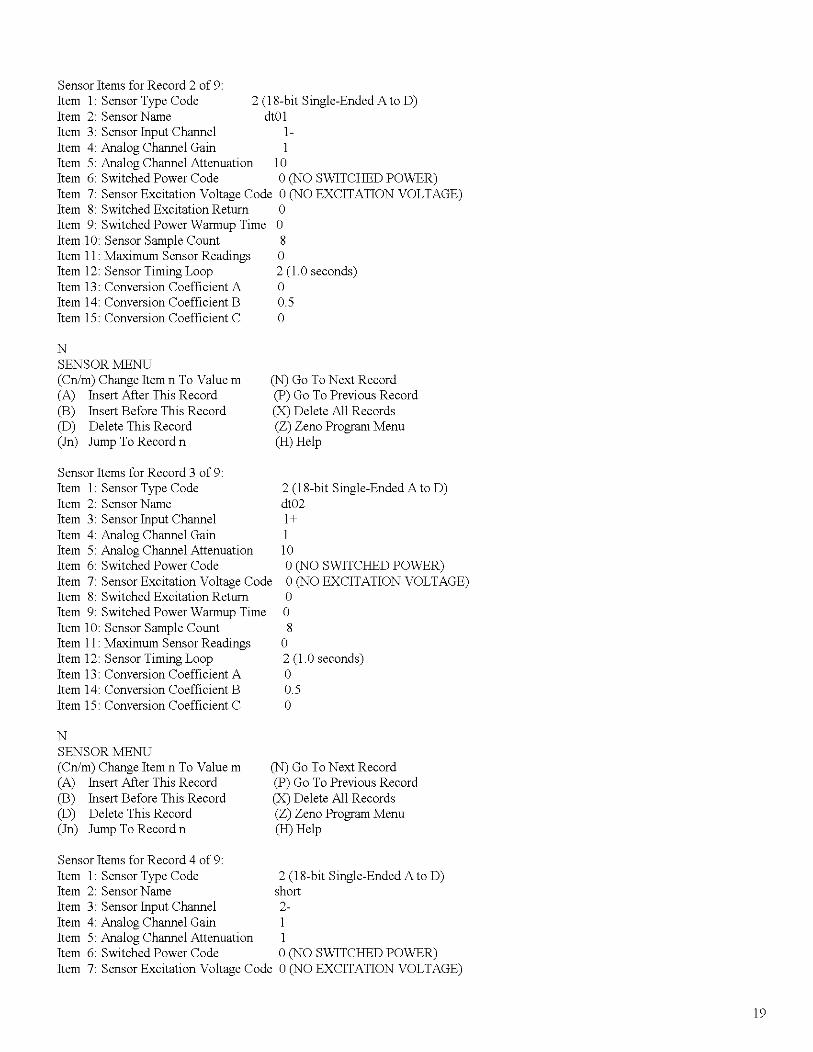
Sensor Items for Record 2 of 9:Item 1: Sensor Type Code 2 (IS-bit Single-Ended A to D)Item 2: Sensor Name dt01Item 3: Sensor Input Channel l-Item 4: Analog Channel Gain 1Item 5: Analog Channel Attenuation 10Item 6: Switched Power Code a(NO SWITCHED POWER)Item 7: Sensor Excitation Voltage Code a(NO EXCITATION VOLTAGE)Item S: Switched Excitation Return aItem 9: Switched Power Warmup Time aItem 10: Sensor Sample Count SItem 11: Maximum Sensor Readings aItem 12: Sensor Timing Loop 2 (1.0 seconds)Item 13: Conversion Coefficient A aItem 14: Conversion Coefficient B 0.5Item 15: Conversion Coefficient C a
NSENSOR MENU(Cn/m) Change Item n To Value m(A) Insert After This Record(B) Insert Before This Record(D) Delete This Record(In) Jump To Record n
(N) Go ToNext Record(P) Go To Previous Record(X) Delete All Records(Z) Zeno Program Menu(H) Help
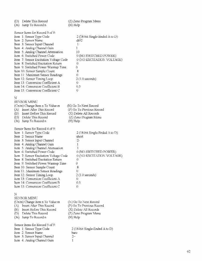
Sensor Items for Record 3 of 9:Item 1: Sensor Type CodeItem 2: Sensor NameItem 3: Sensor Input ChannelItem 4: Analog Channel GainItem 5: Analog Channel AttenuationItem 6: Switched Power CodeItem 7: Sensor Excitation Voltage CodeItem S: Switched Excitation ReturnItem 9: Switched Power Warmup TimeItem 10: Sensor Sample CountItem 11: Maximum Sensor ReadingsItem 12: Sensor Timing LoopItem 13: Conversion Coefficient AItem 14: Conversion Coefficient BItem 15: Conversion Coefficient C
2 (IS-bit Single-Ended A to D)dt021+110a(NO SWITCHED POWER)a(NO EXCITATION VOLTAGE)aaS
a2 (I.aseconds)a0.5a
NSENSOR MENU(Cn/m) Change Item n To Value m(A) Insert After This Record(B) Insert Before This Record(D) Delete This Record(In) Jump To Record n
(N) Go ToNext Record(P) Go To Previous Record(X) Delete All Records(Z) Zeno Program Menu(H) Help
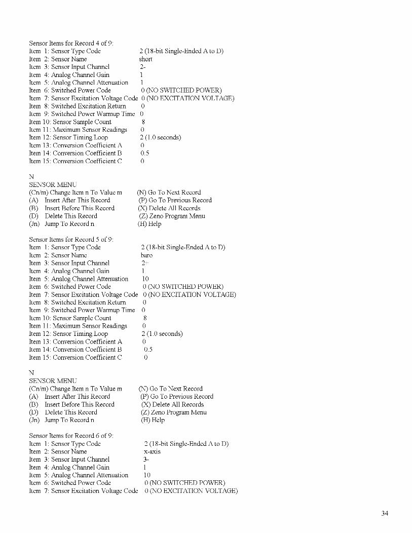
Sensor Items for Record 4 of 9:Item 1: Sensor Type Code 2 (IS-bit Single-Ended A to D)Item 2: Sensor Name shortItem 3: Sensor Input Channel 2-Item 4: Analog Channel Gain 1Item 5: Analog Channel Attenuation 1Item 6: Switched Power Code a(NO SWITCHED POWER)Item 7: Sensor Excitation Voltage Code a(NO EXCITATION VOLTAGE)
(N) Go ToNext Record(P) Go To Previous Record(X) Delete All Records(Z) Zeno Program Menu
21
(In) Jump To Record n
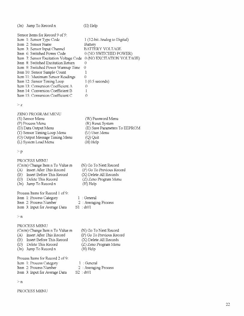
Sensor Items for Record 9 of 9:Item 1: Sensor Type CodeItem 2: Sensor NameItem 3: Sensor Input ChannelItem 6: Switched Power CodeItem 7: Sensor Excitation Voltage CodeItem 8: Switched Excitation ReturnItem 9: Switched Power Warmup TimeItem 10: Sensor Sample CountItem 11: Maximum Sensor ReadingsItem 12: Sensor Timing LoopItem 13: Conversion Coefficient AItem 14: Conversion Coefficient BItem 15: Conversion Coefficient C
>z
ZENO PROGRAM MENU(S) Sensor Menu(P) Process Menu(D) Data Output Menu(T) Sensor Timing Loop Menu(0) Output Message Timing Menu(L) System Load Menu
>p
(H) Help
1 (12-bit Analog to Digital)BatteryBATTERY VOLTAGEo(NO SWITCHED POWER)o(NO EXCITATION VOLTAGE)oo1o1 (0.5 seconds)o1o
(W) Password Menu(R) Reset System(E) Save Parameters To EEPROM(U) User Menu(Q) Quit(H) Help
PROCESS MENU(Cn/m) Change Item n To Value m(A) Insert After This Record(B) Insert Before This Record(D) Delete This Record(In) Jump To Record n
Process Items for Record 1 of 9:Item 1: Process CategoryItem 2: Process NumberItem 3: Input for Average Data
>n
PROCESS MENU(Cn/m) Change Item n To Value m(A) Insert After This Record(B) Insert Before This Record(D) Delete This Record(In) Jump To Record n
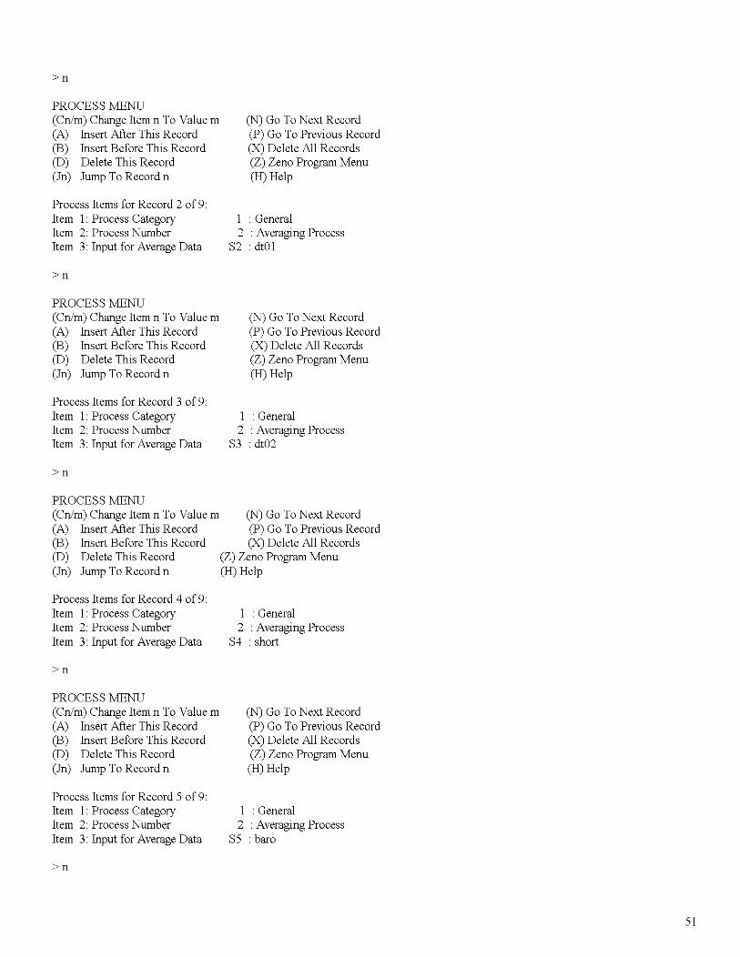
Process Items for Record 2 of 9:Item 1: Process CategoryItem 2: Process NumberItem 3: Input for Average Data
>n
PROCESS MENU
(N) Go ToNext Record(P) Go To Previous Record(X) Delete All Records(Z) Zeno Program Menu(H) Help
1 : General2 : Averaging Process
SI : dlO1
(N) Go ToNext Record(P) Go To Previous Record(X) Delete All Records(Z) Zeno Program Menu(H) Help
1 : General2 : Averaging Process
S2 : dlO1
22
(Cn/m) Change Item n To Value m (N) Go ToNext Record(A) Insert After This Record (P) Go To Previous Record(B) Insert Before This Record (X) Delete All Records(D) Delete This Record (Z) Zeno Program Menu(In) Jump To Record n (H) Help
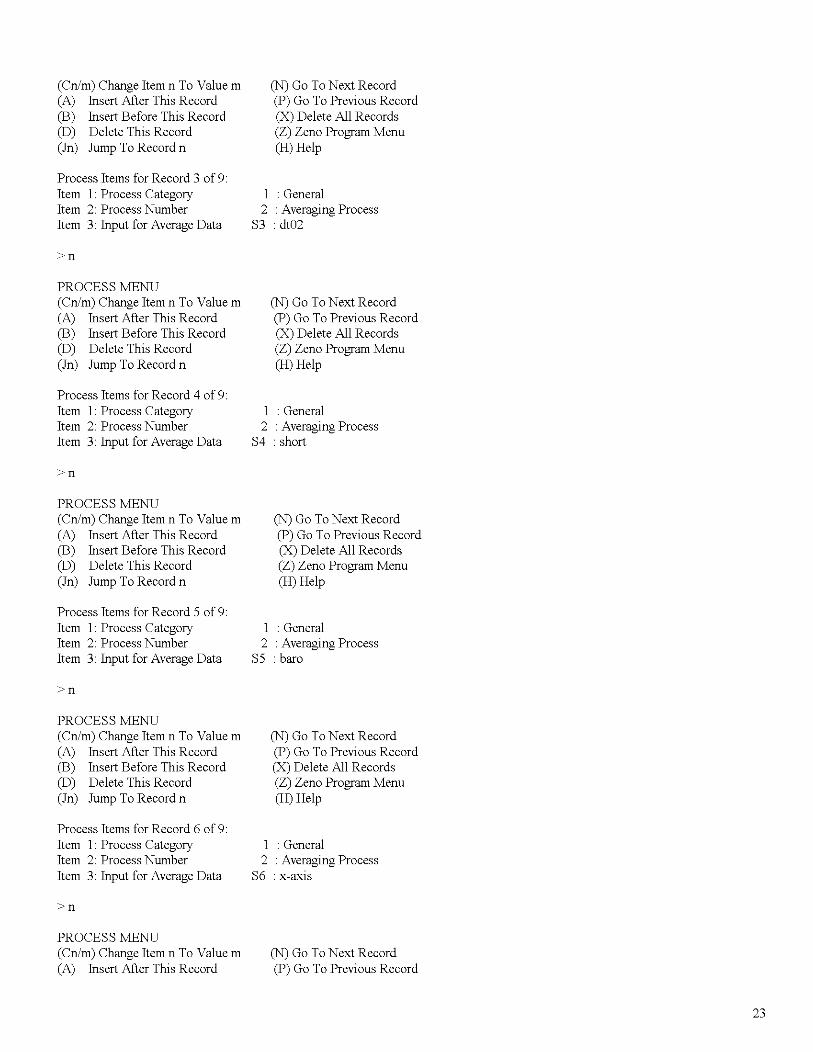
Process Items for Record 3 of 9:Item 1: Process Category 1 : GeneralItem 2: Process Number 2 : Averaging ProcessItem 3: Input for Average Data S3 :dt02
>n
PROCESS MENU(Cn/m) Change Item n To Value m (N) Go ToNext Record(A) Insert After This Record (P) Go To Previous Record(B) Insert Before This Record (X) Delete All Records(D) Delete This Record (Z) Zeno Program Menu(In) Jump To Record n (H) Help
Process Items for Record 4 of 9:Item 1: Process Category 1 : GeneralItem 2: Process Number 2 : Averaging ProcessItem 3: Input for Average Data S4 : short
>n
PROCESS MENU(Cn/m) Change Item n To Value m (N) Go ToNext Record(A) Insert After This Record (P) Go To Previous Record(B) Insert Before This Record (X) Delete All Records(D) Delete This Record (Z) Zeno Program Menu(In) Jump To Record n (H) Help
Process Items for Record 5 of 9:Item 1: Process Category 1 : GeneralItem 2: Process Number 2 : Averaging ProcessItem 3: Input for Average Data S5 : bam
>n
PROCESS MENU(Cn/m) Change Item n To Value m (N) Go ToNext Record(A) Insert After This Record (P) Go To Previous Record(B) Insert Before This Record (X) Delete All Records(D) Delete This Record (Z) Zeno Program Menu(In) Jump To Record n (H) Help
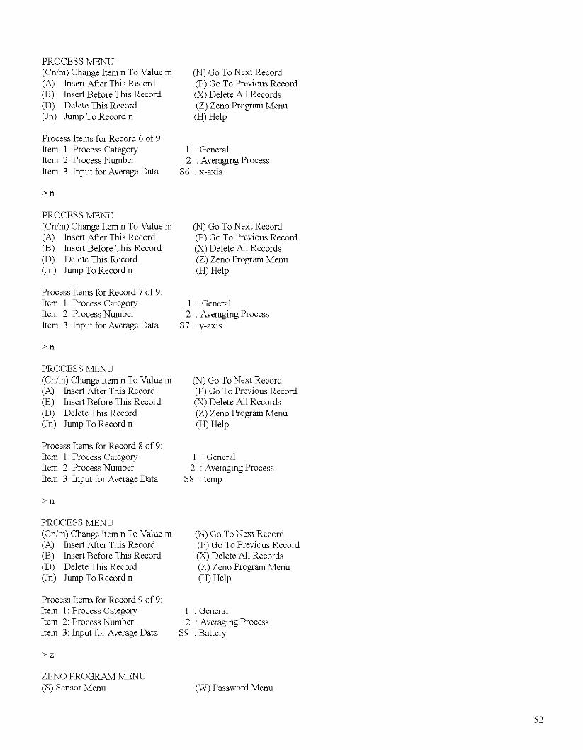
Process Items for Record 6 of 9:Item 1: Process Category 1 : GeneralItem 2: Process Number 2 : Averaging ProcessItem 3: Input for Average Data S6 : x-aXIS
>n
PROCESS MENU(Cn/m) Change Item n To Value m (N) Go ToNext Record(A) Insert After This Record (P) Go To Previous Record
23
(B) Insert Before This Record(D) Delete This Record(In) Jump To Record n
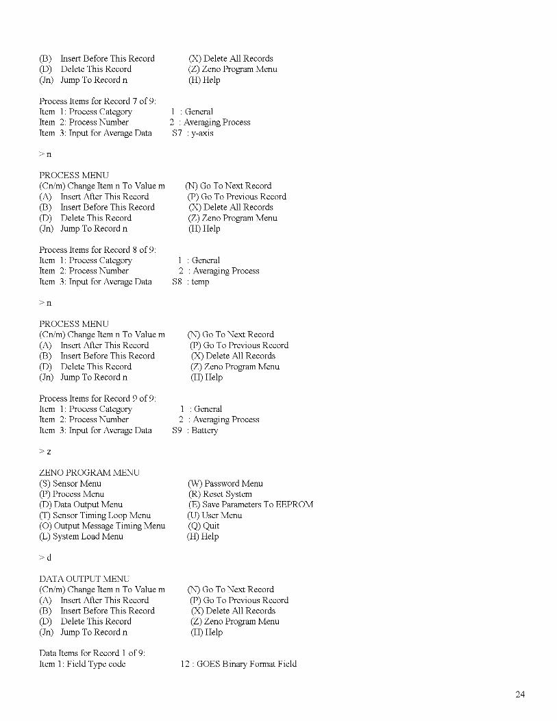
Process Items for Record 7 of 9:Item 1: Process CategoryItem 2: Process NumberItem 3: Input for Average Data
>n
PROCESS MENU(Cn/m) Change Item n To Value m(A) Insert After This Record(B) Insert Before This Record(D) Delete This Record(In) Jump To Record n
Process Items for Record 8 of 9:Item 1: Process CategoryItem 2: Process NumberItem 3: Input for Average Data
>n
PROCESS MENU(Cn/m) Change Item n To Value m(A) Insert After This Record(B) Insert Before This Record(D) Delete This Record(In) Jump To Record n
Process Items for Record 9 of 9:Item 1: Process CategoryItem 2: Process NumberItem 3: Input for Average Data
>z
ZENO PROGRAM MENU(S) Sensor Menu(P) Process Menu(D) Data Output Menu(T) Sensor Timing Loop Menu(0) Output Message Timing Menu(L) System Load Menu
>d
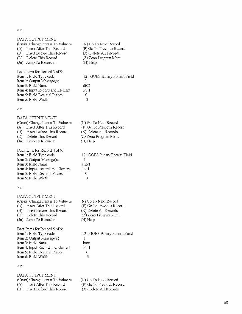
DATA OUTPUT MENU(Cn/m) Change Item n To Value m(A) Insert After This Record(B) Insert Before This Record(D) Delete This Record(In) Jump To Record n
Data Items for Record 1 of 9:Item 1: Field Type code
(X) Delete All Records(Z) Zeno Program Menu(H) Help
: General2 : Averaging ProcessS7 : y-axis
(N) Go ToNext Record(P) Go To Previous Record(X) Delete All Records(Z) Zeno Program Menu(H) Help
1 : General2 : Averaging Process
S8 : temp
(N) Go ToNext Record(P) Go To Previous Record(X) Delete All Records(Z) Zeno Program Menu(H) Help
1 : General2 : Averaging Process
S9 : Battery
(W) Password Menu(R) Reset System(E) Save Parameters To EEPROM(U) User Menu(Q) Quit(H) Help
(N) Go ToNext Record(P) Go To Previous Record(X) Delete All Records(Z) Zeno Program Menu(H) Help
12: GOES Binary Format Field
24
Item 2: Output Message(s) IItem 3: Field Name dlOlItem 4: Input Record and Element PI.IItem 5: Field Decimal Places aItem 6: Field Width 3
>n
DATA OUTPUT MENU(Cn/m) Change Item n To Value m(A) Insert After This Record(B) Insert Before This Record(D) Delete This Record(In) Jump To Record n
Data Items for Record 2 of 9:Item I: Field Type codeItem 2: Output Message(s)Item 3: Field NameItem 4: Input Record and ElementItem 5: Field Decimal PlacesItem 6: Field Width
>n
DATA OUTPUT MENU(Cn/m) Change Item n To Value m(A) Insert After This Record(B) Insert Before This Record(D) Delete This Record(In) Jump To Record n
Data Items for Record 3 of 9:Item I: Field Type codeItem 2: Output Message(s)Item 3: Field NameItem 4: Input Record and ElementItem 5: Field Decimal PlacesItem 6: Field Width
>n
DATA OUTPUT MENU(Cn/m) Change Item n To Value m(A) Insert After This Record(B) Insert Before This Record(D) Delete This Record(In) Jump To Record n
Data Items for Record 4 of 9:Item I: Field Type codeItem 2: Output Message(s)Item 3: Field NameItem 4: Input Record and ElementItem 5: Field Decimal PlacesItem 6: Field Width
>n
(N) Go ToNext Record(P) Go To Previous Record(X) Delete All Records(Z) Zeno Program Menu(H) Help
12: GOES Binary Fonnat FieldI
dlOlP2.1a3
(N) Go ToNext Record(P) Go To Previous Record(X) Delete All Records(Z) Zeno Program Menu(H) Help
12: GOES Binary Fonnat FieldI
dlO2P3.1a3
(N) Go ToNext Record(P) Go To Previous Record(X) Delete All Records(Z) Zeno Program Menu(H) Help
12: GOES Binary Fonnat FieldI
shortP4.1a3
25
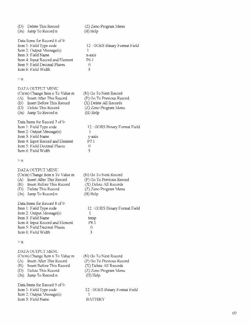
DATA OUTPUT MENU(Cn/m) Change Item n To Value m(A) Insert After This Record(B) Insert Before This Record(D) Delete This Record(In) Jump To Record n
Data Items for Record 5 of 9:Item I: Field Type codeItem 2: Output Message(s)Item 3: Field NameItem 4: Input Record and ElementItem 5: Field Decimal PlacesItem 6: Field Width
>n
DATA OUTPUT MENU(Cn/m) Change Item n To Value m(A) Insert After This Record(B) Insert Before This Record(D) Delete This Record(In) Jump To Record n
Data Items for Record 6 of 9:Item I: Field Type codeItem 2: Output Message(s)Item 3: Field NameItem 4: Input Record and ElementItem 5: Field Decimal PlacesItem 6: Field Width
>n
DATA OUTPUT MENU(Cn/m) Change Item n To Value m(A) Insert After This Record(B) Insert Before This Record(D) Delete This Record(In) Jump To Record n
Data Items for Record 7 of 9:Item I: Field Type codeItem 2: Output Message(s)Item 3: Field NameItem 4: Input Record and ElementItem 5: Field Decimal PlacesItem 6: Field Width
>n
DATA OUTPUT MENU(Cn/m) Change Item n To Value m(A) Insert After This Record(B) Insert Before This Record(D) Delete This Record(In) Jump To Record n
(N) Go ToNext Record(P) Go To Previous Record(X) Delete All Records(Z) Zeno Program Menu(H) Help
12: GOES Binary Format Field1bamP5.1a3
(N) Go ToNext Record(P) Go To Previous Record(X) Delete All Records(Z) Zeno Program Menu(H) Help
12: GOES Binary Format Field1
x-aXIS
P6.1a3
(N) Go ToNext Record(P) Go To Previous Record(X) Delete All Records(Z) Zeno Program Menu(H) Help
12: GOES Binary Format Field1
y-axIsP7.1a3
(N) Go ToNext Record(P) Go To Previous Record(X) Delete All Records(Z) Zeno Program Menu(H) Help
26
Data Items for Record 8 of 9:Item I: Field Type codeItem 2: Output Message(s)Item 3: Field NameItem 4: Input Record and ElementItem 5: Field Decimal PlacesItem 6: Field Width
>n
DATA OUTPUT MENU(Cn/m) Change Item n To Value m(A) Insert After This Record(B) Insert Before This Record(D) Delete This Record(In) Jump To Record n
Data Items for Record 9 of 9:Item I: Field Type codeItem 2: Output Message(s)Item 3: Field NameItem 4: Input Record and ElementItem 5: Field Decimal PlacesItem 6: Field Width
>z
ZENO PROGRAM MENU(S) Sensor Menu(P) Process Menu(D) Data Output Menu(T) Sensor Timing Loop Menu(0) Output Message Timing Menu(L) System Load Menu
>t
SENSOR TIMING LOOP MENU(Cn/m) Change Item n To Value m(Z) Zeno Program Menu
12: GOES Binary Format Field1tempP8.1o3
(N) Go ToNext Record(P) Go To Previous Record(X) Delete All Records(Z) Zeno Program Menu(H) Help
12: GOES Binary Format Field1
BATTERYP9.1o3
(W) Password Menu(R) Reset System(E) Save Parameters To EEPROM(U) User Menu(Q) Quit(H) Help
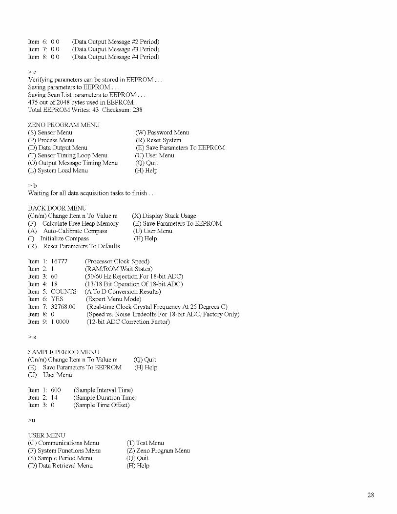
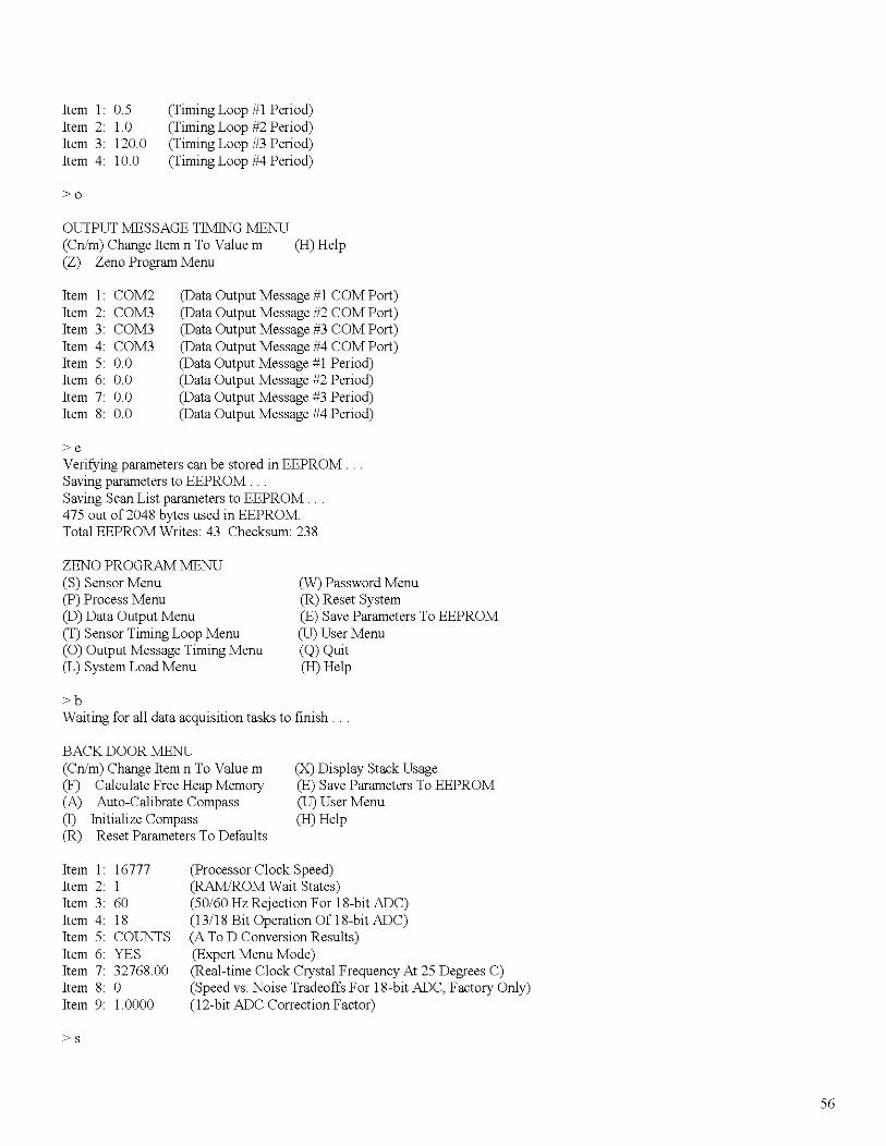
>eVerifying parameters can be stored in EEPROM.Saving parameters to EEPROM.Saving Scan List parameters to EEPROM.475 out of 2048 bytes used in EEPROMTotal EEPROM Writes: 43 Checksum: 238
ZENO PROGRAM MENU(S) Sensor Menu(P) Process Menu(D) Data Output Menu(T) Sensor Timing Loop Menu(0) Output Message Timing Menu(L) System Load Menu
(W) Password Menu(R) Reset System(E) Save Parameters To EEPROM(U) User Menu(Q) Quit(H) Help
>bWaiting for all data acquisition tasks to finish.
BACK DOOR MENU(Cn/m) Change Item n To Value m(F) Calculate Free Heap Memory(A) Auto-Calibrate Compass(I) Initialize Compass(R) Reset Parameters To Defaults
(X) Display Stack Usage(E) Save Parameters To EEPROM(U) User Menu(H) Help
(processor Clock Speed)(RAMIROM Wait States)(50/60 Hz Rejection For 18-bit ADC)(13/18 Bit Operation Of 18-bit ADC)(A To D Conversion Results)(Expert Menu Mode)(Real-time Clock Crystal Frequency At 25 Degrees C)(Speed vs. Noise Tradeoffs For 18-bit ADC, Factory Only)(12-bit ADC Correction Factor)
SAMPLE PERIOD MENU(Cn/m) Change Item n To Value m(E) Save Parameters To EEPROM(U) User Menu
(Q) Quit(H) Help
Item I: 600Item 2: 14Item 3: 0
>u
(Sample Interval Time)(Sample Duration Time)(Sample Time Offset)
USER MENU(C) Communications Menu(F) System Functions Menu(S) Sample Period Menu(D) Data Retrieval Menu
(T) Test Menu(Z) Zeno Program Menu(Q) Quit(H) Help
28
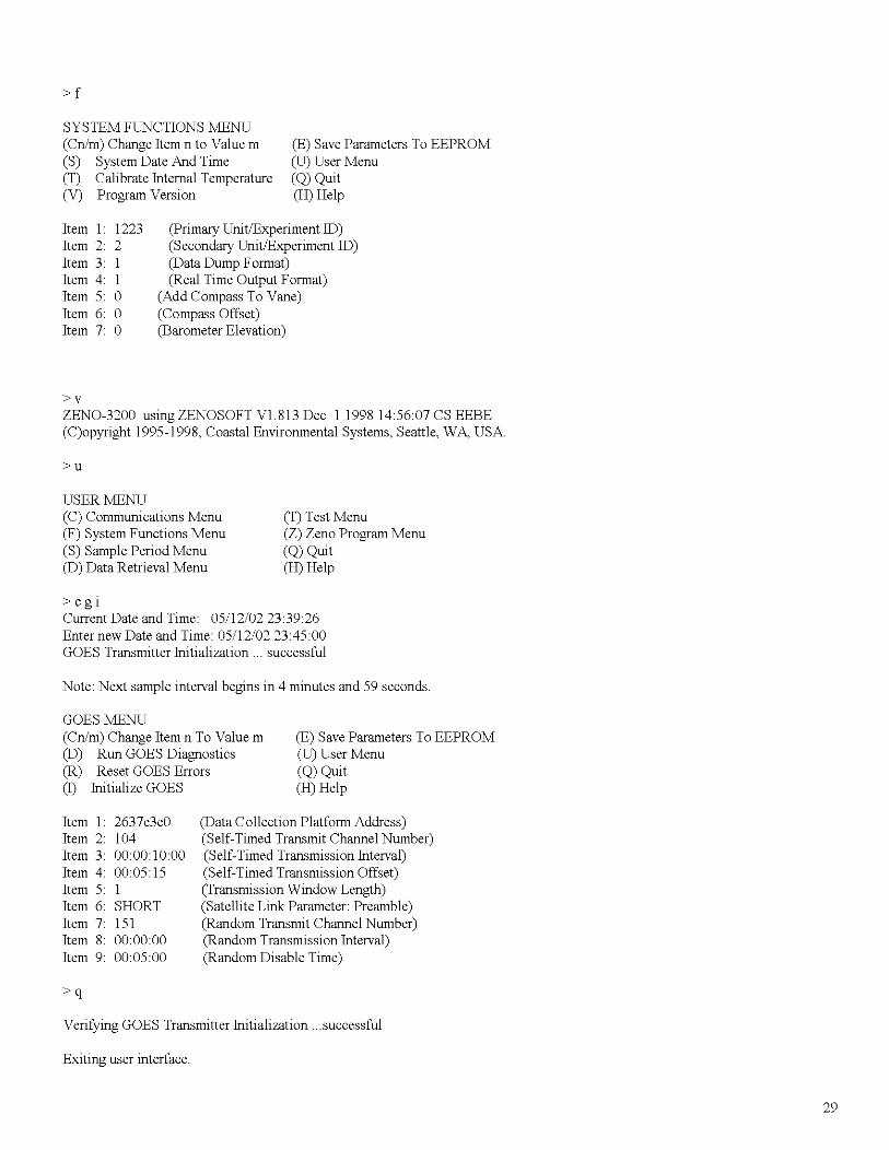
>f
SYSTEM FUNCTIONS MENU(Cn/m) Change Item n to Value m(S) System Date And Time(T) Calibrate Internal Temperature(V) Program Version
(E) Save Parameters To EEPROM(U) User Menu(Q) Quit(H) Help
(COMI Baud Rate)(COM2 Baud Rate)(COM3 Baud Rate)(COMI Port Type)(COM2 Port Type)(COM3 Port Type)(COM3 User Interface Exclusive)(Enable Exclusive CCSAIL Access)
30
>g
GOES MENU(Cn/m) Change Item n To Value m(D) Run GOES Diagnostics(R) Reset GOES Errors(I) Initialize GOES
(E) Save Parameters To EEPROM(U) User Menu(Q) Quit(H) Help
Current Date and Time: 05/12/01 22:51:46Enter new Date and Time: 05/12/0222:53:00GOES Transmitter Initialization ... successfulNote: Next sample interval begins in 6 minutes and 59 seconds.
GOES MENU(Cn/m) Change Item n To Value m(D) Run GOES Diagnostics(R) Reset GOES Errors(I) Initialize GOES
(E) Save Parameters To EEPROM(U) User Menu(Q) Quit(H) Help
USER MENU(C) Communications Menu(F) System Functions Menu(S) Sample Period Menu(D) Data Retrieval Menu
>s
SAMPLE PERIOD MENU(Cn/m) Change Item n To Value m(E) Save Parameters To EEPROM(U) User Menu
( T) Test Menu(Z) Zeno Program Menu(Q) Quit(H) Help
(Q) Quit(H) Help
Item 1: 600 (Sample Interval Time)
31
Item 2: 14Item 3: 0
(Sample Duration Time)(Sample Time Offset)
>uChecking Scan List records.
USER MENU(C) Communications Menu(F) System Functions Menu(S) Sample Period Menu(D) Data Retrieval Menu
>zUSERMENU(C) Communications Menu(F) System Functions Menu(S) Sample Period Menu(D) Data Retrieval Menu
>z
(T) Test Menu(Z) Zeno Program Menu(Q) Quit(H) Help
(T) Test Menu(Z) Zeno Program Menu
(Q) Quit(H) Help
Enter Administrator Password: ****
Waiting for all data acquisition tasks to finish.
ZENO PROGRAM MENU(S) Sensor Menu(P) Process Menu(D) Data Output Menu(T) Sensor Timing Loop Menu(0) Output Message Timing Menu(L) System Load Menu
S
SENSOR MENU(Cn/m) Change Item n To Value m(A) Insert After This Record(B) Insert Before This Record(D) Delete This Record(In) Jump To Record n
Sensor Items for Record I of 9:Item I: Sensor Type CodeItem 2: Sensor NameItem 3: Sensor Input ChannelItem 4: Analog Channel GainItem 5: Analog Channel AttenuationItem 6: Switched Power CodeItem 7: Sensor Excitation Voltage CodeItem 8: Switched Excitation ReturnItem 9: Switched Power Warmup TimeItem 10: Sensor Sample CountItem II: Maximum Sensor ReadingsItem 12: Sensor Timing LoopItem 13: Conversion Coefficient AItem 14: Conversion Coefficient BItem 15: Conversion Coefficient C
(W) Password Menu(R) Reset System(E) Save Parameters To EEPROM(U) User Menu(Q) Quit(H) Help
(N) Go ToNext Record(P) Go To Previous Record(X) Delete All Records(Z) Zeno Program Menu(H) Help
2 (l8-bit Single-Ended A to D)dlOlI-IIo(NO SWITCHED POWER)o(NO EXCITATION VOLTAGE)oo8o2 (I.0 seconds)o0.5o
32
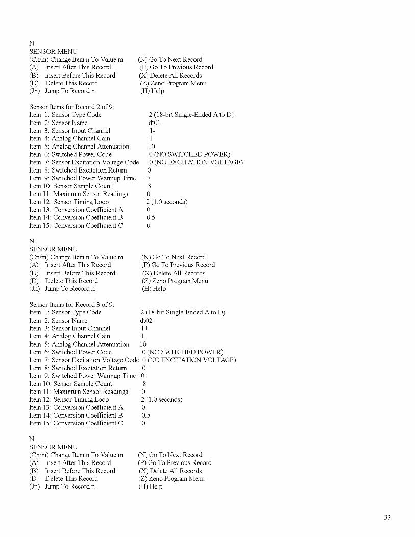
NSENSOR MENU(Cn/m) Change Item n To Value m(A) Insert After This Record(B) Insert Before This Record(D) Delete This Record(In) Jump To Record n
(N) Go ToNext Record(P) Go To Previous Record(X) Delete All Records(Z) Zeno Program Menu(H) Help
Sensor Items for Record 2 of 9:Item I: Sensor Type CodeItem 2: Sensor NameItem 3: Sensor Input ChannelItem 4: Analog Channel GainItem 5: Analog Channel AttenuationItem 6: Switched Power CodeItem 7: Sensor Excitation Voltage CodeItem 8: Switched Excitation ReturnItem 9: Switched Power Warmup TimeItem 10: Sensor Sample CountItem II: Maximum Sensor ReadingsItem 12: Sensor Timing LoopItem 13: Conversion Coefficient AItem 14: Conversion Coefficient BItem 15: Conversion Coefficient C
NSENSOR MENU(Cn/m) Change Item n To Value m(A) Insert After This Record(B) Insert Before This Record(D) Delete This Record(In) Jump To Record n
2 (l8-bit Single-Ended A to D)dtOlI-I10a(NO SWITCHED POWER)a(NO EXCITATION VOLTAGE)aa8a2 (I.aseconds)a0.5a
(N) Go ToNext Record(P) Go To Previous Record(X) Delete All Records(Z) Zeno Program Menu(H) Help
Sensor Items for Record 3 of 9:Item I: Sensor Type Code 2 (l8-bit Single-Ended A to D)Item 2: Sensor Name dt02Item 3: Sensor Input Channel 1+Item 4: Analog Channel Gain IItem 5: Analog Channel Attenuation 10Item 6: Switched Power Code a(NO SWITCHED POWER)Item 7: Sensor Excitation Voltage Code a(NO EXCITATION VOLTAGE)Item 8: Switched Excitation Return aItem 9: Switched Power Warmup Time aItem 10: Sensor Sample Count 8Item II: Maximum Sensor Readings aItem 12: Sensor Timing Loop 2 (1.0 seconds)Item 13: Conversion Coefficient A aItem 14: Conversion Coefficient B 0.5Item 15: Conversion Coefficient C a
NSENSOR MENU(Cn/m) Change Item n To Value m(A) Insert After This Record(B) Insert Before This Record(D) Delete This Record(In) Jump To Record n
(N) Go ToNext Record(P) Go To Previous Record(X) Delete All Records(Z) Zeno Program Menu(H) Help
33
Sensor Items for Record 4 of 9:Item 1: Sensor Type Code 2 (IS-bit Single-Ended A to D)Item 2: Sensor Name shortItem 3: Sensor Input Channel 2-Item 4: Analog Channel Gain 1Item 5: Analog Channel Attenuation 1Item 6: Switched Power Code a(NO SWITCHED POWER)Item 7: Sensor Excitation Voltage Code a(NO EXCITATION VOLTAGE)Item S: Switched Excitation Return aItem 9: Switched Power Warmup Time aItem 10: Sensor Sample Count SItem 11: Maximum Sensor Readings aItem 12: Sensor Timing Loop 2 (1.0 seconds)Item 13: Conversion Coefficient A aItem 14: Conversion Coefficient B 0.5Item 15: Conversion Coefficient C a
NSENSOR MENU(Cn/m) Change Item n To Value m(A) Insert After This Record(B) Insert Before This Record(D) Delete This Record(In) Jump To Record n
(N) Go ToNext Record(P) Go To Previous Record(X) Delete All Records(Z) Zeno Program Menu(H) Help
Sensor Items for Record 5 of 9:Item 1: Sensor Type CodeItem 2: Sensor NameItem 3: Sensor Input ChannelItem 4: Analog Channel GainItem 5: Analog Channel AttenuationItem 6: Switched Power CodeItem 7: Sensor Excitation Voltage CodeItem S: Switched Excitation ReturnItem 9: Switched Power Warmup TimeItem 10: Sensor Sample CountItem 11: Maximum Sensor ReadingsItem 12: Sensor Timing LoopItem 13: Conversion Coefficient AItem 14: Conversion Coefficient BItem 15: Conversion Coefficient C
NSENSOR MENU(Cn/m) Change Item n To Value m(A) Insert After This Record(B) Insert Before This Record(D) Delete This Record(In) Jump To Record n
Sensor Items for Record 6 of 9:Item 1: Sensor Type CodeItem 2: Sensor NameItem 3: Sensor Input ChannelItem 4: Analog Channel GainItem 5: Analog Channel AttenuationItem 6: Switched Power CodeItem 7: Sensor Excitation Voltage Code
2 (IS-bit Single-Ended A to D)bam2+110a(NO SWITCHED POWER)a(NO EXCITATION VOLTAGE)aaSa2 (I.aseconds)a0.5a
(N) Go ToNext Record(P) Go To Previous Record(X) Delete All Records(Z) Zeno Program Menu(H) Help
NSENSOR MENU(Cn/m) Change Item n To Value m(A) Insert After This Record(B) Insert Before This Record(D) Delete This Record(In) Jump To Record n
oo8o2 (I.0 seconds)o0.5o
(N) Go ToNext Record(P) Go To Previous Record(X) Delete All Records(Z) Zeno Program Menu(H) Help
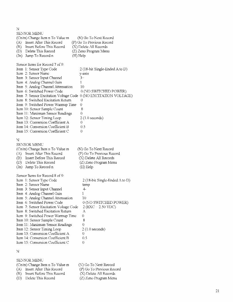
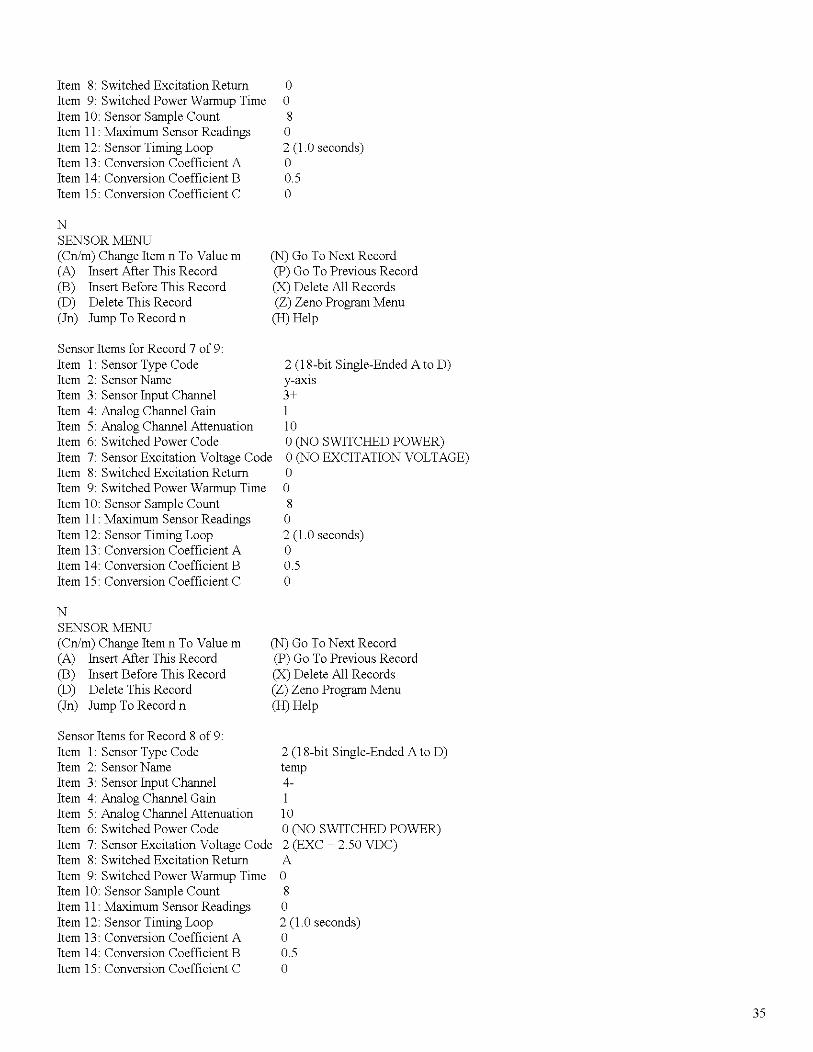
Sensor Items for Record 7 of 9:Item 1: Sensor Type CodeItem 2: Sensor NameItem 3: Sensor Input ChannelItem 4: Analog Channel GainItem 5: Analog Channel AttenuationItem 6: Switched Power CodeItem 7: Sensor Excitation Voltage CodeItem 8: Switched Excitation ReturnItem 9: Switched Power Warmup TimeItem 10: Sensor Sample CountItem 11: Maximum Sensor ReadingsItem 12: Sensor Timing LoopItem 13: Conversion Coefficient AItem 14: Conversion Coefficient BItem 15: Conversion Coefficient C
2 (l8-bit Single-Ended A to D)y-axIs3+110o(NO SWITCHED POWER)o(NO EXCITATION VOLTAGE)oo8o2 (I.0 seconds)o0.5o
NSENSOR MENU(Cn/m) Change Item n To Value m(A) Insert After This Record(B) Insert Before This Record(D) Delete This Record(In) Jump To Record n
(N) Go ToNext Record(P) Go To Previous Record(X) Delete All Records(Z) Zeno Program Menu(H) Help
Sensor Items for Record 8 of 9:Item 1: Sensor Type CodeItem 2: Sensor NameItem 3: Sensor Input ChannelItem 4: Analog Channel GainItem 5: Analog Channel AttenuationItem 6: Switched Power CodeItem 7: Sensor Excitation Voltage CodeItem 8: Switched Excitation ReturnItem 9: Switched Power Warmup TimeItem 10: Sensor Sample CountItem 11: Maximum Sensor ReadingsItem 12: Sensor Timing LoopItem 13: Conversion Coefficient AItem 14: Conversion Coefficient BItem 15: Conversion Coefficient C
2 (l8-bit Single-Ended A to D)temp4-110o(NO SWITCHED POWER)2 (EXC ~ 2.50 VDC)Ao8o2 (I.0 seconds)o0.5o
35
N
SENSOR MENU(Cn/m) Change Item n To Value m(A) Insert After This Record(B) Insert Before This Record(D) Delete This Record(In) Jump To Record n
(N) Go ToNext Record(P) Go To Previous Record(X) Delete All Records(Z) Zeno Program Menu(H) Help
Sensor Items for Record 9 of 9:Item 1: Sensor Type CodeItem 2: Sensor NameItem 3: Sensor Input ChannelItem 6: Switched Power CodeItem 7: Sensor Excitation Voltage CodeItem 8: Switched Excitation ReturnItem 9: Switched Power Warmup TimeItem 10: Sensor Sample CountItem 11: Maximum Sensor ReadingsItem 12: Sensor Timing LoopItem 13: Conversion Coefficient AItem 14: Conversion Coefficient BItem 15: Conversion Coefficient C
>z
ZENO PROGRAM MENU(S) Sensor Menu(P) Process Menu(D) Data Output Menu(T) Sensor Timing Loop Menu(0) Output Message Timing Menu(L) System Load Menu
>p
PROCESS MENU(Cn/m) Change Item n To Value m(A) Insert After This Record(B) Insert Before This Record(D) Delete This Record(In) Jump To Record n
1 (12-bit Analog to Digital)BatteryBATTERY VOLTAGEo(NO SWITCHED POWER)o(NO EXCITATION VOLTAGE)oo1
o1 (0.5 seconds)o1o
(W) Password Menu(R) Reset System(E) Save Parameters To EEPROM(U) User Menu(Q) Quit(H) Help
(N) Go ToNext Record(P) Go To Previous Record(X) Delete All Records(Z) Zeno Program Menu(H) Help
Process Items for Record 1 of 9:Item 1: Process CategoryItem 2: Process NumberItem 3: Input for Average Data
>n
PROCESS MENU(Cn/m) Change Item n To Value m(A) Insert After This Record(B) Insert Before This Record(D) Delete This Record(In) Jump To Record n
1 : General2 : Averaging Process
SI : dlO1
(N) Go ToNext Record(P) Go To Previous Record(X) Delete All Records(Z) Zeno Program Menu(H) Help
36
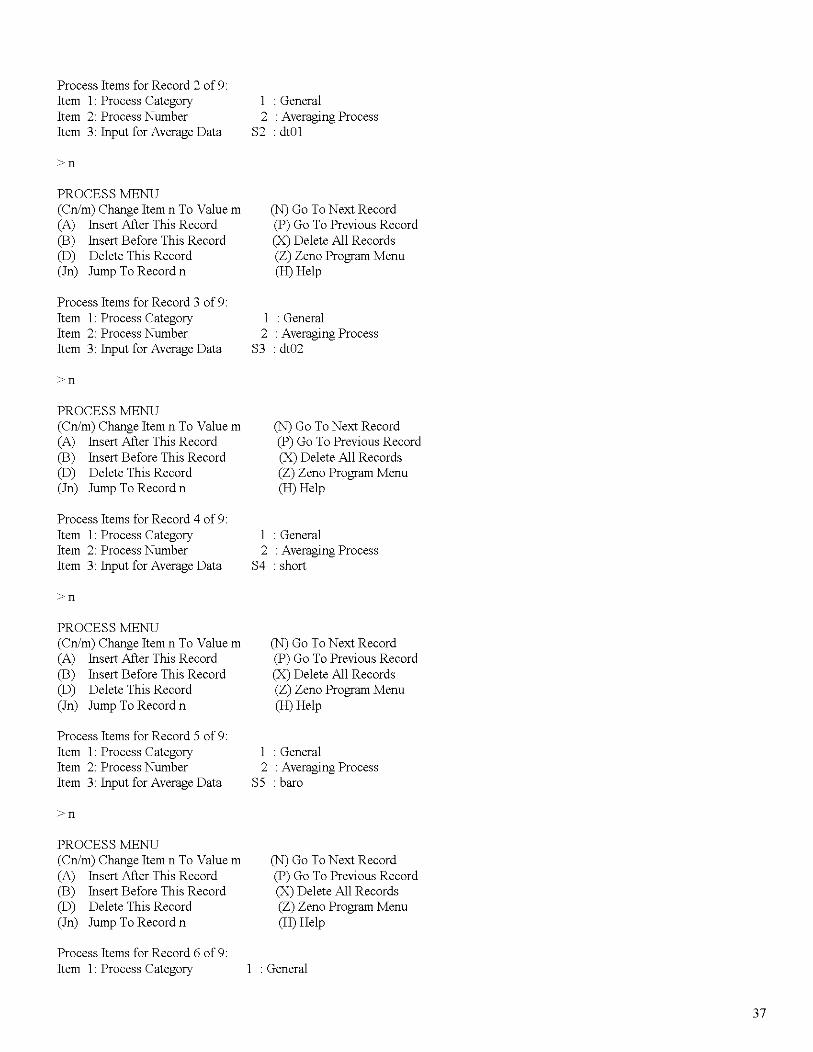
Process Items for Record 2 of 9:Item ]: Process Category ] : GeneralItem 2: Process Number 2 : Averaging ProcessItem 3: Input for Average Data S2 : dtO]
>n
PROCESS MENU(Cn/m) Change Item n To Value m (N) Go ToNext Record(A) Insert After This Record (P) Go To Previous Record(B) Insert Before This Record (X) Delete All Records(D) Delete This Record (Z) Zeno Program Menu(In) Jump To Record n (H) Help
Process Items for Record 3 of 9:Item ]: Process Category ] : GeneralItem 2: Process Number 2 : Averaging ProcessItem 3: Input for Average Data S3 :dt02
>n
PROCESS MENU(Cn/m) Change Item n To Value m (N) Go ToNext Record(A) Insert After This Record (P) Go To Previous Record(B) Insert Before This Record (X) Delete All Records(D) Delete This Record (Z) Zeno Program Menu(In) Jump To Record n (H) Help
Process Items for Record 4 of 9:Item ]: Process Category ] : GeneralItem 2: Process Number 2 : Averaging ProcessItem 3: Input for Average Data S4 : short
>n
PROCESS MENU(Cn/m) Change Item n To Value m (N) Go ToNext Record(A) Insert After This Record (P) Go To Previous Record(B) Insert Before This Record (X) Delete All Records(D) Delete This Record (Z) Zeno Program Menu(In) Jump To Record n (H) Help
Process Items for Record 5 of 9:Item ]: Process Category ] : GeneralItem 2: Process Number 2 : Averaging ProcessItem 3: Input for Average Data S5 : bam
>n
PROCESS MENU(Cn/m) Change Item n To Value m (N) Go ToNext Record(A) Insert After This Record (P) Go To Previous Record(B) Insert Before This Record (X) Delete All Records(D) Delete This Record (Z) Zeno Program Menu(In) Jump To Record n (H) Help
Process Items for Record 6 of 9:Item ]: Process Category : General
37
Item 2: Process NumberItem 3: Input for Average Data
>n
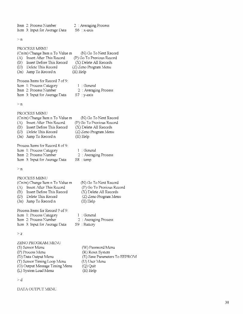
2 : Averaging ProcessS6 : x-axis
PROCESS MENU(Cn/m) Change Item n To Value m (N) Go To Next Record(A) Insert After This Record (P) Go To Previous Record(B) Insert Before This Record (X) Delete All Records(D) Delete This Record (Z) Zeno Program Menu(In) Jump To Record n (H) Help
Process Items for Record 7 of 9:Item 1: Process CategoryItem 2: Process NumberItem 3: Input for Average Data
>n
PROCESS MENU(Cn/m) Change Item n To Value m(A) Insert After This Record(B) Insert Before This Record(D) Delete This Record(In) Jump To Record n
Process Items for Record 8 of 9:Item 1: Process CategoryItem 2: Process NumberItem 3: Input for Average Data
>n
PROCESS MENU(Cn/m) Change Item n To Value m(A) Insert After This Record(B) Insert Before This Record(D) Delete This Record(In) Jump To Record n
Process Items for Record 9 of 9:Item 1: Process CategoryItem 2: Process NumberItem 3: Input for Average Data
>z
ZENO PROGRAM MENU(S) Sensor Menu(P) Process Menu(D) Data Output Menu(T) Sensor Timing Loop Menu(0) Output Message Timing Menu(L) System Load Menu
>d
DATA OUTPUT MENU
1 : General2 : Averaging Process
S7 : y-axIs
(N) Go ToNext Record(P) Go To Previous Record(X) Delete All Records(Z) Zeno Program Menu(H) Help
1 : General2 : Averaging Process
S8 : temp
(N) Go ToNext Record(P) Go To Previous Record(X) Delete All Records(Z) Zeno Program Menu(H) Help
1 : General2 : Averaging Process
S9 : Battery
(W) Password Menu(R) Reset System(E) Save Parameters To EEPROM(U) User Menu(Q) Quit(H) Help
38
(Cn/m) Change Item n To Value m(A) Insert After This Record(B) Insert Before This Record(D) Delete This Record(In) Jump To Record n
Data Items for Record 1 of 9:Item I: Field Type codeItem 2: Output Message(s)Item 3: Field NameItem 4: Input Record and ElementItem 5: Field Decimal PlacesItem 6: Field Width
>n
DATA OUTPUT MENU(Cn/m) Change Item n To Value m(A) Insert After This Record(B) Insert Before This Record(D) Delete This Record(In) Jump To Record n
Data Items for Record 2 of 9:Item I: Field Type codeItem 2: Output Message(s)Item 3: Field NameItem 4: Input Record and ElementItem 5: Field Decimal PlacesItem 6: Field Width
>n
DATA OUTPUT MENU(Cn/m) Change Item n To Value m(A) Insert After This Record(B) Insert Before This Record(D) Delete This Record(In) Jump To Record n
Data Items for Record 3 of 9:Item I: Field Type codeItem 2: Output Message(s)Item 3: Field NameItem 4: Input Record and ElementItem 5: Field Decimal PlacesItem 6: Field Width
>n
DATA OUTPUT MENU(Cn/m) Change Item n To Value m(A) Insert After This Record(B) Insert Before This Record(D) Delete This Record(In) Jump To Record n
Data Items for Record 4 of 9:
(N) Go ToNext Record(P) Go To Previous Record(X) Delete All Records(Z) Zeno Program Menu(H) Help
12: GOES Binary Format Field1
dlOlPl.la3
(N) Go ToNext Record(P) Go To Previous Record(X) Delete All Records(Z) Zeno Program Menu(H) Help
12: GOES Binary Format Field1
dlOlP2.la3
(N) Go ToNext Record(P) Go To Previous Record(X) Delete All Records(Z) Zeno Program Menu(H) Help
12: GOES Binary Format Field1
dlO2P3.1a3
(N) Go ToNext Record(P) Go To Previous Record(X) Delete All Records(Z) Zeno Program Menu(H) Help
39
Item I: Field Type codeItem 2: Output Message(s)Item 3: Field NameItem 4: Input Record and ElementItem 5: Field Decimal PlacesItem 6: Field Width
>n
DATA OUTPUT MENU(Cn/m) Change Item n To Value m(A) Insert After This Record(B) Insert Before This Record(D) Delete This Record(In) Jump To Record n
Data Items for Record 5 of 9:Item I: Field Type codeItem 2: Output Message(s)Item 3: Field NameItem 4: Input Record and ElementItem 5: Field Decimal PlacesItem 6: Field Width
>n
DATA OUTPUT MENU(Cn/m) Change Item n To Value m(A) Insert After This Record(B) Insert Before This Record(D) Delete This Record(In) Jump To Record n
Data Items for Record 6 of 9:Item I: Field Type codeItem 2: Output Message(s)Item 3: Field NameItem 4: Input Record and ElementItem 5: Field Decimal PlacesItem 6: Field Width
>n
DATA OUTPUT MENU(Cn/m) Change Item n To Value m(A) Insert After This Record(B) Insert Before This Record(D) Delete This Record(In) Jump To Record n
Data Items for Record 7 of 9:Item I: Field Type codeItem 2: Output Message(s)Item 3: Field NameItem 4: Input Record and ElementItem 5: Field Decimal PlacesItem 6: Field Width
12: GOES Binary Format Field1shortP4.1o3
(N) Go ToNext Record(P) Go To Previous Record(X) Delete All Records(Z) Zeno Program Menu(H) Help
12: GOES Binary Format Field1
bamP5.1o3
(N) Go ToNext Record(P) Go To Previous Record(X) Delete All Records(Z) Zeno Program Menu(H) Help
12: GOES Binary Format Field1
x-aXIS
P6.1o3
(N) Go ToNext Record(P) Go To Previous Record(X) Delete All Records(Z) Zeno Program Menu(H) Help
12: GOES Binary Format Field1y-axIsP7.1o3
40
>n
DATA OUTPUT MENU(Cn/m) Change Item n To Value m(A) Insert After This Record(B) Insert Before This Record(D) Delete This Record(In) Jump To Record n
Data Items for Record 8 of 9:Item I: Field Type codeItem 2: Output Message(s)Item 3: Field NameItem 4: Input Record and ElementItem 5: Field Decimal PlacesItem 6: Field Width
>n
DATA OUTPUT MENU(Cn/m) Change Item n To Value m(A) Insert After This Record(B) Insert Before This Record(D) Delete This Record(In) Jump To Record n
Data Items for Record 9 of 9:Item I: Field Type codeItem 2: Output Message(s)Item 3: Field NameItem 4: Input Record and ElementItem 5: Field Decimal PlacesItem 6: Field Width
>z
ZENO PROGRAM MENU(S) Sensor Menu(P) Process Menu(D) Data Output Menu(T) Sensor Timing Loop Menu(0) Output Message Timing Menu(L) System Load Menu
>t
SENSOR TIMING LOOP MENU(Cn/m) Change Item n To Value m(Z) Zeno Program Menu
(N) Go ToNext Record(P) Go To Previous Record(X) Delete All Records(Z) Zeno Program Menu(H) Help
12: GOES Binary Format Field1
tempP8.1o3
(N) Go ToNext Record(P) Go To Previous Record(X) Delete All Records(Z) Zeno Program Menu(H) Help
12: GOES Binary Format Field1
BATTERYP9.1o3
(W) Password Menu(R) Reset System(E) Save Parameters To EEPROM(U) User Menu(Q) Quit(H) Help
>eVerifying parameters can be stored in EEPROM.Saving parameters to EEPROM.Saving Scan List parameters to EEPROM.475 out of 2048 bytes used in EEPROMTotal EEPROM Writes: 43 Checksum: 238
ZENO PROGRAM MENU(S) Sensor Menu (W) Password Menu(P) Process Menu (R) Reset System(D) Data Output Menu (E) Save Parameters To EEPROM(T) Sensor Timing Loop Menu (U) User Menu(0) Output Message Timing Menu (Q) Quit(L) System Load Menu (H) Help
>bWaiting for all data acquisition tasks to finish.
BACK DOOR MENU(Cn/m) Change Item n To Value m(F) Calculate Free Heap Memory(A) Auto-Calibrate Compass(I) Initialize Compass(R) Reset Parameters To Defaults
(X) Display Stack Usage(E) Save Parameters To EEPROM(U) User Menu(H) Help
(Processor Clock Speed)(RAMIROM Wait States)(50/60 Hz Rejection For 18-bit ADC)(13/18 Bit Operation Of 18-bit ADC)(A To D Conversion Results)(Expert Menu Mode)(Real-time Clock Crystal Frequency At 25 Degrees C)(Speed vs. Noise Tradeoffs For 18-bit ADC, Factory Only)(12-bit ADC Correction Factor)
SAMPLE PERIOD MENU(Cn/m) Change Item n To Value m(E) Save Parameters To EEPROM(U) User Menu
(Q) Quit(H) Help
Item I: 600Item 2: 14Item 3: 0
(Sample Interval Time)(Sample Duration Time)(Sample Time Offset)
42
>u
USER MENU(C) Communications Menu(F) System Functions Menu(S) Sample Period Menu(D) Data Retrieval Menu
>f
SYSTEM FUNCTIONS MENU(Cn/m) Change Item n to Value m(S) System Date And Time(T) Calibrate Internal Temperature(V) Program Version
(T) Test Menu(Z) Zeno Program Menu(Q) Quit(H) Help
(E) Save Parameters To EEPROM(U) User Menu(Q) Quit(H) Help
Current Date and Time: 05/12/01 22:51:46Enter new Date and Time: 05/12/0222:53:00GOES Transmitter Initialization ... successfulNote: Next sample interval begins in 6 minutes and 59 seconds.
GOES MENU(Cn/m) Change Item n To Value m(D) Run GOES Diagnostics(R) Reset GOES Errors(I) Initialize GOES
(E) Save Parameters To EEPROM(U) User Menu(Q) Quit(H) Help
USER MENU(C) Communications Menu(F) System Functions Menu(S) Sample Period Menu(D) Data Retrieval Menu
>s
SAMPLE PERIOD MENU(Cn/m) Change Item n To Value m(E) Save Parameters To EEPROM(U) User Menu
(T) Test Menu(Z) Zeno Program Menu(Q) Quit(H) Help
(Q) Quit(H) Help
Item I: 600Item 2: 14Item 3: 0
(Sample Interval Time)(Sample Duration Time)(Sample Time Offset)
>uChecking Scan List records.
USER MENU(C) Communications Menu(F) System Functions Menu(S) Sample Period Menu(D) Data Retrieval Menu
>z
Enter Administrator Password: ****
(T) Test Menu(Z) Zeno Program Menu(Q) Quit(H) Help
Waiting for all data acquisition tasks to finish.
ZENO PROGRAM MENU(S) Sensor Menu(P) Process Menu(D) Data Output Menu(T) Sensor Timing Loop Menu(0) Output Message Timing Menu(L) System Load Menu
S
SENSOR MENU(Cn/m) Change Item n To Value m(A) Insert After This Record(B) Insert Before This Record(D) Delete This Record(In) Jump To Record n
Sensor Items for Record I of 9:Item I: Sensor Type CodeItem 2: Sensor NameItem 3: Sensor Input ChannelItem 4: Analog Channel GainItem 5: Analog Channel AttenuationItem 6: Switched Power CodeItem 7: Sensor Excitation Voltage Code
(W) Password Menu(R) Reset System(E) Save Parameters To EEPROM(U) User Menu(Q) Quit(H) Help
(N) Go ToNext Record(P) Go To Previous Record(X) Delete All Records(Z) Zeno Program Menu(H) Help
2 (IS-bit Single-Ended A to D)dlOlI-IIo(NO SWITCHED POWER)o(NO EXCITATION VOLTAGE)
NSENSOR MENU(Cn/m) Change Item n To Value m(A) Insert After This Record(B) Insert Before This Record(D) Delete This Record(In) Jump To Record n
(N) Go ToNext Record(P) Go To Previous Record(X) Delete All Records(Z) Zeno Program Menu(H) Help
Sensor Items for Record 7 of 9:Item 1: Sensor Type CodeItem 2: Sensor NameItem 3: Sensor Input ChannelItem 4: Analog Channel GainItem 5: Analog Channel AttenuationItem 6: Switched Power CodeItem 7: Sensor Excitation Voltage CodeItem 8: Switched Excitation ReturnItem 9: Switched Power Warmup TimeItem 10: Sensor Sample CountItem 11: Maximum Sensor ReadingsItem 12: Sensor Timing LoopItem 13: Conversion Coefficient AItem 14: Conversion Coefficient BItem 15: Conversion Coefficient C
NSENSOR MENU(Cn/m) Change Item n To Value m(A) Insert After This Record(B) Insert Before This Record(D) Delete This Record(In) Jump To Record n
Sensor Items for Record 8 of 9:Item 1: Sensor Type CodeItem 2: Sensor NameItem 3: Sensor Input ChannelItem 4: Analog Channel GainItem 5: Analog Channel AttenuationItem 6: Switched Power Code
(N) Go ToNext Record(P) Go To Previous Record(X) Delete All Records(Z) Zeno Program Menu(H) Help
2 (l8-bit Single-Ended A to D)temp4-
110o(NO SWITCHED POWER)
49
Item 7: Sensor Excitation Voltage CodeItem 8: Switched Excitation ReturnItem 9: Switched Power Warmup TimeItem 10: Sensor Sample CountItem 11: Maximum Sensor ReadingsItem 12: Sensor Timing LoopItem 13: Conversion Coefficient AItem 14: Conversion Coefficient BItem 15: Conversion Coefficient C
N
2 (EXC ~ 2.50 VDC)Aa8a2 (I.aseconds)a0.5a
SENSOR MENU(Cn/m) Change Item n To Value m(A) Insert After This Record(B) Insert Before This Record(D) Delete This Record(In) Jump To Record n
(N) Go ToNext Record(P) Go To Previous Record(X) Delete All Records(Z) Zeno Program Menu(H) Help
Sensor Items for Record 9 of 9:Item 1: Sensor Type CodeItem 2: Sensor NameItem 3: Sensor Input ChannelItem 6: Switched Power CodeItem 7: Sensor Excitation Voltage CodeItem 8: Switched Excitation ReturnItem 9: Switched Power Warmup TimeItem 10: Sensor Sample CountItem 11: Maximum Sensor ReadingsItem 12: Sensor Timing LoopItem 13: Conversion Coefficient AItem 14: Conversion Coefficient BItem 15: Conversion Coefficient C
>z
ZENO PROGRAM MENU(S) Sensor Menu(P) Process Menu(D) Data Output Menu(T) Sensor Timing Loop Menu(0) Output Message Timing Menu(L) System Load Menu
>p
1 (12-bit Analog to Digital)BatteryBATTERY VOLTAGEa(NO SWITCHED POWER)a(NO EXCITATION VOLTAGE)aa1a1 (0.5 seconds)a1a
(W) Password Menu(R) Reset System(E) Save Parameters To EEPROM
(U) User Menu(Q) Quit(H) Help
PROCESS MENU(Cn/m) Change Item n To Value m(A) Insert After This Record(B) Insert Before This Record(D) Delete This Record(In) Jump To Record n
Process Items for Record 1 of 9:Item 1: Process CategoryItem 2: Process NumberItem 3: Input for Average Data
(N) Go ToNext Record(P) Go To Previous Record(X) Delete All Records(Z) Zeno Program Menu(H) Help
1 : General2 : Averaging Process
SI : dlO1
50
>n
PROCESS MENU(Cn/m) Change Item n To Value m(A) Insert After This Record(B) Insert Before This Record(D) Delete This Record(In) Jump To Record n
Process Items for Record 2 of 9:Item ]: Process CategoryItem 2: Process NumberItem 3: Input for Average Data
>n
PROCESS MENU(Cn/m) Change Item n To Value m(A) Insert After This Record(B) Insert Before This Record(D) Delete This Record(In) Jump To Record n
Process Items for Record 3 of 9:Item ]: Process CategoryItem 2: Process NumberItem 3: Input for Average Data
>n
PROCESS MENU(Cn/m) Change Item n To Value m(A) Insert After This Record(B) Insert Before This Record(D) Delete This Record(In) Jump To Record n
Process Items for Record 4 of 9:Item ]: Process CategoryItem 2: Process NumberItem 3: Input for Average Data
>n
PROCESS MENU(Cn/m) Change Item n To Value m(A) Insert After This Record(B) Insert Before This Record(D) Delete This Record(In) Jump To Record n
Process Items for Record 5 of 9:Item ]: Process CategoryItem 2: Process NumberItem 3: Input for Average Data
>n
(N) Go ToNext Record(P) Go To Previous Record(X) Delete All Records(Z) Zeno Program Menu(H) Help
] : General2 : Averaging Process
S2 : dtO]
(N) Go ToNext Record(P) Go To Previous Record(X) Delete All Records(Z) Zeno Program Menu(H) Help
] : General2 : Averaging Process
S3 : dt02
(N) Go ToNext Record(P) Go To Previous Record(X) Delete All Records
(Z) Zeno Program Menu(H) Help
] : General2 : Averaging Process
S4 : short
(N) Go ToNext Record(P) Go To Previous Record(X) Delete All Records(Z) Zeno Program Menu(H) Help
] : General2 : Averaging Process
S5 : baro
5]
PROCESS MENU(Cn/m) Change Item n To Value m(A) Insert After This Record(B) Insert Before This Record(D) Delete This Record(In) Jump To Record n
Process Items for Record 6 of 9:Item I: Process CategoryItem 2: Process NumberItem 3: Input for Average Data
>n
PROCESS MENU(Cn/m) Change Item n To Value m(A) Insert After This Record(B) Insert Before This Record(D) Delete This Record(In) Jump To Record n
Process Items for Record 7 of 9:Item I: Process CategoryItem 2: Process NumberItem 3: Input for Average Data
>n
PROCESS MENU(Cn/m) Change Item n To Value m(A) Insert After This Record(B) Insert Before This Record(D) Delete This Record(In) Jump To Record n
Process Items for Record 8 of 9:Item I: Process CategoryItem 2: Process NumberItem 3: Input for Average Data
>n
PROCESS MENU(Cn/m) Change Item n To Value m(A) Insert After This Record(B) Insert Before This Record(D) Delete This Record(In) Jump To Record n
Process Items for Record 9 of 9:Item I: Process CategoryItem 2: Process NumberItem 3: Input for Average Data
>z
ZENO PROGRAM MENU(S) Sensor Menu
(N) Go ToNext Record(P) Go To Previous Record(X) Delete All Records(Z) Zeno Program Menu(H) Help
I : General2 : Averaging Process
S6 : x-aXIS
(N) Go ToNext Record(P) Go To Previous Record(X) Delete All Records(Z) Zeno Program Menu(H) Help
I : General2 : Averaging Process
S7 : y-axIs
(N) Go ToNext Record(P) Go To Previous Record(X) Delete All Records(Z) Zeno Program Menu(H) Help
I : General2 : Averaging Process
S8 : temp
(N) Go ToNext Record(P) Go To Previous Record(X) Delete All Records(Z) Zeno Program Menu(H) Help
I : General2 : Averaging Process
S9 : Battery
(W) Password Menu
52
(P) Process Menu(D) Data Output Menu(T) Sensor Timing Loop Menu(0) Output Message Timing Menu(L) System Load Menu
>d
DATA OUTPUT MENU(Cn/m) Change Item n To Value m(A) Insert After This Record(B) Insert Before This Record(D) Delete This Record(In) Jump To Record n
Data Items for Record 1 of 9:Item I: Field Type codeItem 2: Output Message(s)Item 3: Field NameItem 4: Input Record and ElementItem 5: Field Decimal PlacesItem 6: Field Width
>n
DATA OUTPUT MENU(Cn/m) Change Item n To Value m(A) Insert After This Record(B) Insert Before This Record(D) Delete This Record(In) Jump To Record n
(R) Reset System(E) Save Parameters To EEPROM
(U) User Menu(Q) Quit(H) Help
(N) Go ToNext Record(P) Go To Previous Record(X) Delete All Records(Z) Zeno Program Menu(H) Help
12: GOES Binary Format Field1
dlOlPl.la3
(N) Go ToNext Record(P) Go To Previous Record(X) Delete All Records(Z) Zeno Program Menu(H) Help
Data Items for Record 2 of 9:Item 1: Field Type code 12: GOES Binary Format FieldItem 2: Output Message(s) 1Item 3: Field Name dlOlItem 4: Input Record and Element P2.1Item 5: Field Decimal Places aItem 6: Field Width 3
>n
DATA OUTPUT MENU(Cn/m) Change Item n To Value m(A) Insert After This Record(B) Insert Before This Record(D) Delete This Record(In) Jump To Record n
Data Items for Record 3 of 9:Item I: Field Type codeItem 2: Output Message(s)Item 3: Field NameItem 4: Input Record and ElementItem 5: Field Decimal PlacesItem 6: Field Width
>n
(N) Go ToNext Record(P) Go To Previous Record(X) Delete All Records(Z) Zeno Program Menu(H) Help
12: GOES Binary Format Field1dlO2P3.1
a3
53
DATA OUTPUT MENU(Cn/m) Change Item n To Value m(A) Insert After This Record(B) Insert Before This Record(D) Delete This Record(In) Jump To Record n
Data Items for Record 4 of 9:Item I: Field Type codeItem 2: Output Message(s)Item 3: Field NameItem 4: Input Record and ElementItem 5: Field Decimal PlacesItem 6: Field Width
>n
DATA OUTPUT MENU(Cn/m) Change Item n To Value m(A) Insert After This Record(B) Insert Before This Record(D) Delete This Record(In) Jump To Record n
Data Items for Record 5 of 9:Item I: Field Type codeItem 2: Output Message(s)Item 3: Field NameItem 4: Input Record and ElementItem 5: Field Decimal PlacesItem 6: Field Width
>n
DATA OUTPUT MENU(Cn/m) Change Item n To Value m(A) Insert After This Record(B) Insert Before This Record(D) Delete This Record(In) Jump To Record n
Data Items for Record 6 of 9:Item I: Field Type codeItem 2: Output Message(s)Item 3: Field NameItem 4: Input Record and ElementItem 5: Field Decimal PlacesItem 6: Field Width
>n
DATA OUTPUT MENU(Cn/m) Change Item n To Value m(A) Insert After This Record(B) Insert Before This Record(D) Delete This Record(In) Jump To Record n
(N) Go ToNext Record(P) Go To Previous Record(X) Delete All Records(Z) Zeno Program Menu(H) Help
12: GOES Binary Format Field1
shortP4.1a3
(N) Go ToNext Record(P) Go To Previous Record(X) Delete All Records(Z) Zeno Program Menu(H) Help
12: GOES Binary Format Field1bamP5.1a3
(N) Go ToNext Record(P) Go To Previous Record(X) Delete All Records(Z) Zeno Program Menu(H) Help
12: GOES Binary Format Field1x-aXIS
P6.1a3
(N) Go ToNext Record(P) Go To Previous Record(X) Delete All Records(Z) Zeno Program Menu(H) Help
54
Data Items for Record 7 of 9:Item I: Field Type codeItem 2: Output Message(s)Item 3: Field NameItem 4: Input Record and ElementItem 5: Field Decimal PlacesItem 6: Field Width
>n
DATA OUTPUT MENU(Cn/m) Change Item n To Value m(A) Insert After This Record(B) Insert Before This Record(D) Delete This Record(In) Jump To Record n
Data Items for Record 8 of 9:Item I: Field Type codeItem 2: Output Message(s)Item 3: Field NameItem 4: Input Record and ElementItem 5: Field Decimal PlacesItem 6: Field Width
>n
DATA OUTPUT MENU(Cn/m) Change Item n To Value m(A) Insert After This Record(B) Insert Before This Record(D) Delete This Record(In) Jump To Record n
Data Items for Record 9 of 9:Item I: Field Type codeItem 2: Output Message(s)Item 3: Field NameItem 4: Input Record and ElementItem 5: Field Decimal PlacesItem 6: Field Width
>z
ZENO PROGRAM MENU(S) Sensor Menu(P) Process Menu(D) Data Output Menu(T) Sensor Timing Loop Menu(0) Output Message Timing Menu(L) System Load Menu
>t
SENSOR TIMING LOOP MENU(Cn/m) Change Item n To Value m(Z) Zeno Program Menu
12: GOES Binary Format Field1
y-axIsP7.1a3
(N) Go ToNext Record(P) Go To Previous Record(X) Delete All Records(Z) Zeno Program Menu(H) Help
12: GOES Binary Format Field1tempP8.1a3
(N) Go ToNext Record(P) Go To Previous Record(X) Delete All Records(Z) Zeno Program Menu(H) Help
12: GOES Binary Format Field1
BATTERYP9.1a3
(W) Password Menu(R) Reset System(E) Save Parameters To EEPROM(U) User Menu(Q) Quit(H) Help
>eVerifying parameters can be stored in EEPROM.Saving parameters to EEPROM.Saving Scan List parameters to EEPROM.475 out of 2048 bytes used in EEPROMTotal EEPROM Writes: 43 Checksum: 238
ZENO PROGRAM MENU(S) Sensor Menu(P) Process Menu(D) Data Output Menu(T) Sensor Timing Loop Menu(0) Output Message Timing Menu(L) System Load Menu
(W) Password Menu(R) Reset System(E) Save Parameters To EEPROM(U) User Menu(Q) Quit(H) Help
>bWaiting for all data acquisition tasks to finish.
BACK DOOR MENU(Cn/m) Change Item n To Value m(F) Calculate Free Heap Memory(A) Auto-Calibrate Compass(I) Initialize Compass(R) Reset Parameters To Defaults
(X) Display Stack Usage(E) Save Parameters To EEPROM(U) User Menu(H) Help
(Processor Clock Speed)(RAMIROM Wait States)(50/60 Hz Rejection For 18-bit ADC)(13/18 Bit Operation Of 18-bit ADC)(A To D Conversion Results)(Expert Menu Mode)(Real-time Clock Crystal Frequency At 25 Degrees C)(Speed vs. Noise Tradeoffs For 18-bit ADC, Factory Only)(12-bit ADC Correction Factor)
56
SAMPLE PERIOD MENU(Cn/m) Change Item n To Value m(E) Save Parameters To EEPROM(U) User Menu
(Q) Quit(H) Help
Item 1: 600Item 2: 14Item 3: 0
>u
(Sample Interval Time)(Sample Duration Time)(Sample Time Offset)
USER MENU(C) Communications Menu(F) System Functions Menu(S) Sample Period Menu(D) Data Retrieval Menu
>f
SYSTEM FUNCTIONS MENU(Cn/m) Change Item n to Value m(S) System Date And Time(T) Calibrate Internal Temperature(V) Program Version
(T) Test Menu(Z) Zeno Program Menu(Q) Quit(H) Help
(E) Save Parameters To EEPROM(U) User Menu(Q) Quit(H) Help
Current Date and Time: 05/12/01 22:51:46Enter new Date and Time: 05/12/0222:53:00GOES Transmitter Initialization ... successfulNote: Next sample interval begins in 6 minutes and 59 seconds.
GOES MENU(Cn/m) Change Item n To Value m(D) Run GOES Diagnostics(R) Reset GOES Errors
(E) Save Parameters To EEPROM(U) User Menu(Q) Quit
SENSOR MENU(Cn/m) Change Item n To Value m(A) Insert After This Record(B) Insert Before This Record(D) Delete This Record(In) Jump To Record n
(N) Go ToNext Record(P) Go To Previous Record(X) Delete All Records(Z) Zeno Program Menu(H) Help
Sensor Items for Record 9 of 9:Item 1: Sensor Type CodeItem 2: Sensor NameItem 3: Sensor Input ChannelItem 6: Switched Power CodeItem 7: Sensor Excitation Voltage CodeItem 8: Switched Excitation ReturnItem 9: Switched Power Warmup TimeItem 10: Sensor Sample CountItem 11: Maximum Sensor ReadingsItem 12: Sensor Timing LoopItem 13: Conversion Coefficient AItem 14: Conversion Coefficient BItem 15: Conversion Coefficient C
>z
ZENO PROGRAM MENU(S) Sensor Menu(P) Process Menu
1 (l2-bit Analog to Digital)BatteryBATTERY VOLTAGEo(NO SWITCHED POWER)o(NO EXCITATION VOLTAGE)oo1o1 (0.5 seconds)o1o
(W) Password Menu(R) Reset System
64
(D) Data Output Menu(T) Sensor Timing Loop Menu(0) Output Message Timing Menu(L) System Load Menu
>p
PROCESS MENU(Cn/m) Change Item n To Value m(A) Insert After This Record(B) Insert Before This Record(D) Delete This Record(In) Jump To Record n
Process Items for Record] of 9:Item ]: Process CategoryItem 2: Process NumberItem 3: Input for Average Data
>n
PROCESS MENU(Cn/m) Change Item n To Value m(A) Insert After This Record(B) Insert Before This Record(D) Delete This Record(In) Jump To Record n
Process Items for Record 2 of 9:Item ]: Process CategoryItem 2: Process NumberItem 3: Input for Average Data
>n
PROCESS MENU(Cn/m) Change Item n To Value m(A) Insert After This Record(B) Insert Before This Record(D) Delete This Record(In) Jump To Record n
Process Items for Record 3 of 9:Item ]: Process CategoryItem 2: Process NumberItem 3: Input for Average Data
>n
PROCESS MENU(Cn/m) Change Item n To Value m(A) Insert After This Record(B) Insert Before This Record(D) Delete This Record(In) Jump To Record n
Process Items for Record 4 of 9:Item ]: Process Category
(E) Save Parameters To EEPROM(U) User Menu(Q) Quit(H) Help
(N) Go ToNext Record(P) Go To Previous Record(X) Delete All Records(Z) Zeno Program Menu(H) Help
] : General2 : Averaging Process
S] : dlO]
(N) Go ToNext Record(P) Go To Previous Record(X) Delete All Records(Z) Zeno Program Menu(H) Help
] : General2 : Averaging Process
S2 : dlO]
(N) Go ToNext Record(P) Go To Previous Record(X) Delete All Records(Z) Zeno Program Menu(H) Help
] : General2 : Averaging Process
S3 : dlO2
(N) Go ToNext Record(P) Go To Previous Record(X) Delete All Records(Z) Zeno Program Menu(H) Help
: General
65
Item 2: Process NumberItem 3: Input for Average Data
>n
PROCESS MENU(Cn/m) Change Item n To Value m(A) Insert After This Record(B) Insert Before This Record(D) Delete This Record(In) Jump To Record n
Process Items for Record 5 of 9:Item 1: Process CategoryItem 2: Process NumberItem 3: Input for Average Data
>n
PROCESS MENU(Cn/m) Change Item n To Value m(A) Insert After This Record(B) Insert Before This Record(D) Delete This Record(In) Jump To Record n
Process Items for Record 6 of 9:Item 1: Process CategoryItem 2: Process NumberItem 3: Input for Average Data
>n
PROCESS MENU(Cn/m) Change Item n To Value m(A) Insert After This Record(B) Insert Before This Record(D) Delete This Record(In) Jump To Record n
Process Items for Record 7 of 9:Item 1: Process CategoryItem 2: Process NumberItem 3: Input for Average Data
>n
PROCESS MENU(Cn/m) Change Item n To Value m(A) Insert After This Record(B) Insert Before This Record(D) Delete This Record(In) Jump To Record n
Process Items for Record 8 of 9:Item 1: Process CategoryItem 2: Process NumberItem 3: Input for Average Data
2 : Averaging ProcessS4 : short
(N) Go ToNext Record(P) Go To Previous Record(X) Delete All Records(Z) Zeno Program Menu(H) Help
1 : General2 : Averaging Process
S5 : baro
(N) Go ToNext Record(P) Go To Previous Record(X) Delete All Records(Z) Zeno Program Menu(H) Help
1 : General2 : Averaging Process
S6 : x-aXIS
(N) Go ToNext Record(P) Go To Previous Record(X) Delete All Records(Z) Zeno Program Menu(H) Help
1 : General2 : Averaging Process
S7 : y-axIs
(N) Go ToNext Record(P) Go To Previous Record(X) Delete All Records(Z) Zeno Program Menu(H) Help
1 : General2 : Averaging Process
S8 : temp
66
>n
PROCESS MENU(Cn/m) Change Item n To Value m(A) Insert After This Record(B) Insert Before This Record(D) Delete This Record(In) Jump To Record n
Process Items for Record 9 of 9:Item I: Process CategoryItem 2: Process NumberItem 3: Input for Average Data
>z
ZENO PROGRAM MENU(S) Sensor Menu(P) Process Menu(D) Data Output Menu(T) Sensor Timing Loop Menu(0) Output Message Timing Menu(L) System Load Menu
>d
DATA OUTPUT MENU(Cn/m) Change Item n To Value m(A) Insert After This Record(B) Insert Before This Record(D) Delete This Record(In) Jump To Record n
Data Items for Record 1 of 9:Item I: Field Type codeItem 2: Output Message(s)Item 3: Field NameItem 4: Input Record and ElementItem 5: Field Decimal PlacesItem 6: Field Width
>n
DATA OUTPUT MENU(Cn/m) Change Item n To Value m(A) Insert After This Record(B) Insert Before This Record(D) Delete This Record(In) Jump To Record n
Data Items for Record 2 of 9:Item I: Field Type codeItem 2: Output Message(s)Item 3: Field NameItem 4: Input Record and ElementItem 5: Field Decimal PlacesItem 6: Field Width
(N) Go ToNext Record(P) Go To Previous Record(X) Delete All Records(Z) Zeno Program Menu(H) Help
1 : General2 : Averaging Process
S9 : Battery
(W) Password Menu(R) Reset System(E) Save Parameters To EEPROM(U) User Menu(Q) Quit(H) Help
(N) Go ToNext Record(P) Go To Previous Record(X) Delete All Records(Z) Zeno Program Menu(H) Help
12: GOES Binary Format Field1dlOlPl.la3
(N) Go ToNext Record(P) Go To Previous Record(X) Delete All Records(Z) Zeno Program Menu(H) Help
12: GOES Binary Format Field1
dlOlP2.1a3
67
>n
DATA OUTPUT MENU(Cn/m) Change Item n To Value m(A) Insert After This Record(B) Insert Before This Record(D) Delete This Record(In) Jump To Record n
Data Items for Record 3 of 9:Item I: Field Type codeItem 2: Output Message(s)Item 3: Field NameItem 4: Input Record and ElementItem 5: Field Decimal PlacesItem 6: Field Width
>n
DATA OUTPUT MENU(Cn/m) Change Item n To Value m(A) Insert After This Record(B) Insert Before This Record(D) Delete This Record(In) Jump To Record n
Data Items for Record 4 of 9:Item I: Field Type codeItem 2: Output Message(s)Item 3: Field NameItem 4: Input Record and ElementItem 5: Field Decimal PlacesItem 6: Field Width
>n
DATA OUTPUT MENU(Cn/m) Change Item n To Value m(A) Insert After This Record(B) Insert Before This Record(D) Delete This Record(In) Jump To Record n
Data Items for Record 5 of 9:Item I: Field Type codeItem 2: Output Message(s)Item 3: Field NameItem 4: Input Record and ElementItem 5: Field Decimal PlacesItem 6: Field Width
>n
DATA OUTPUT MENU(Cn/m) Change Item n To Value m(A) Insert After This Record(B) Insert Before This Record
(N) Go ToNext Record(P) Go To Previous Record(X) Delete All Records(Z) Zeno Program Menu(H) Help
12: GOES Binary Format Field1
dt02P3.1a3
(N) Go ToNext Record(P) Go To Previous Record(X) Delete All Records(Z) Zeno Program Menu(H) Help
12: GOES Binary Format Field1
shortP4.1
a3
(N) Go ToNext Record(P) Go To Previous Record(X) Delete All Records(Z) Zeno Program Menu(H) Help
12: GOES Binary Format Field1
bamP5.1
a3
(N) Go ToNext Record(P) Go To Previous Record(X) Delete All Records
68
(D) Delete This Record(In) Jump To Record n
Data Items for Record 6 of 9:Item I: Field Type codeItem 2: Output Message(s)Item 3: Field NameItem 4: Input Record and ElementItem 5: Field Decimal PlacesItem 6: Field Width
>n
DATA OUTPUT MENU(Cn/m) Change Item n To Value m(A) Insert After This Record(B) Insert Before This Record(D) Delete This Record(In) Jump To Record n
Data Items for Record 7 of 9:Item I: Field Type codeItem 2: Output Message(s)Item 3: Field NameItem 4: Input Record and ElementItem 5: Field Decimal PlacesItem 6: Field Width
>n
DATA OUTPUT MENU(Cn/m) Change Item n To Value m(A) Insert After This Record(B) Insert Before This Record(D) Delete This Record(In) Jump To Record n
Data Items for Record 8 of 9:Item I: Field Type codeItem 2: Output Message(s)Item 3: Field NameItem 4: Input Record and ElementItem 5: Field Decimal PlacesItem 6: Field Width
>n
DATA OUTPUT MENU(Cn/m) Change Item n To Value m(A) Insert After This Record(B) Insert Before This Record(D) Delete This Record(In) Jump To Record n
Data Items for Record 9 of 9:Item I: Field Type codeItem 2: Output Message(s)Item 3: Field Name
(Z) Zeno Program Menu(H) Help
12: GOES Binary Format Field1
x-aXIS
P6.1a3
(N) Go ToNext Record(P) Go To Previous Record(X) Delete All Records(Z) Zeno Program Menu(H) Help
12: GOES Binary Format Field1
y-axIsP7.1a3
(N) Go ToNext Record(P) Go To Previous Record(X) Delete All Records(Z) Zeno Program Menu(H) Help
12: GOES Binary Format Field1
tempP8.1a3
(N) Go ToNext Record(P) Go To Previous Record(X) Delete All Records(Z) Zeno Program Menu(H) Help
12: GOES Binary Format Field1
BATTERY
69
Item 4: Input Record and Element P9.1Item 5: Field Decimal Places 0Item 6: Field Width 3
>z
ZENO PROGRAM MENU(S) Sensor Menu(P) Process Menu(D) Data Output Menu(T) Sensor Timing Loop Menu(0) Output Message Timing Menu(L) System Load Menu
>t
SENSOR TIMING LOOP MENU(Cn/m) Change Item n To Value m(Z) Zeno Program Menu
(W) Password Menu(R) Reset System(E) Save Parameters To EEPROM(U) User Menu(Q) Quit(H) Help
>eVerifying parameters can be stored in EEPROM.Saving parameters to EEPROM.Saving Scan List parameters to EEPROM.475 out of 2048 bytes used in EEPROMTotal EEPROM Writes: 43 Checksum: 238
ZENO PROGRAM MENU(S) Sensor Menu(P) Process Menu(D) Data Output Menu(T) Sensor Timing Loop Menu(0) Output Message Timing Menu(L) System Load Menu
(W) Password Menu(R) Reset System(E) Save Parameters To EEPROM(U) User Menu(Q) Quit
(H) Help
>bWaiting for all data acquisition tasks to finish.
70
BACK DOOR MENU(Cn/m) Change Item n To Value m(F) Calculate Free Heap Memory(A) Auto-Calibrate Compass(I) Initialize Compass(R) Reset Parameters To Defaults
(X) Display Stack Usage(E) Save Parameters To EEPROM(U) User Menu(H) Help
(processor Clock Speed)(RAMIROM Wait States)(50/60 Hz Rejection For 18-bit ADC)(13/18 Bit Operation Of 18-bit ADC)(A To D Conversion Results)(Expert Menu Mode)(Real-time Clock Crystal Frequency At 25 Degrees C)(Speed vs. Noise Tradeoffs For 18-bit ADC, Factory Only)(12-bit ADC Correction Factor)
SAMPLE PERIOD MENU(Cn/m) Change Item n To Value m(E) Save Parameters To EEPROM(U) User Menu
(Q) Quit(H) Help
Item I: 600Item 2: 14Item 3: 0
>u
(Sample Interval Time)(Sample Duration Time)(Sample Time Offset)
USER MENU(C) Communications Menu(F) System Functions Menu(S) Sample Period Menu(D) Data Retrieval Menu
>f
SYSTEM FUNCTIONS MENU(Cn/m) Change Item n to Value m(S) System Date And Time(T) Calibrate Internal Temperature(V) Program Version
(T) Test Menu(Z) Zeno Program Menu(Q) Quit(H) Help
(E) Save Parameters To EEPROM(U) User Menu(Q) Quit(H) Help
Item 1: 1223 (primary Unit/Experiment ill)Item 2: 2 (Secondary Unit/Experiment ill)Item 3: I (Data Dump Format)Item 4: I (Real Time Output Format)Item 5: 0 (Add Compass To Vane)Item 6: 0 (Compass Offset)Item 7: 0 (Barometer Elevation)
>vZENO-3200 using ZENOSOFT V1.813 Dec I 1998 145607 CS EEBE(C)opyright 1995-1998, Coastal Enviromnental Systems, Seattle, WA, USA
71
>u
USER MENU(C) Communications Menu(F) System Functions Menu(S) Sample Period Menu(D) Data Retrieval Menu
(T) Test Menu(Z) Zeno Program Menu(Q) Quit(H) Help
> c g iCurrent Date and Time: 05/12/0223:39:26Enter new Date and Time: 05/12/0223:45:00GOES Transmitter Initialization ... successful
Note: Next sample interval begins in 4 minutes and 59 seconds.
GOES MENU(Cn/m) Change Item n To Value m(D) Run GOES Diagnostics(R) Reset GOES Errors(I) Initialize GOES
(E) Save Parameters To EEPROM(U) User Menu(Q) Quit(H) Help
An alternate to entering the progrannning by hand would be to download the configuration:
72
To Configure a ZENO using a laptop and program from a Diskette
1 hook black ZENO db9 cable to ZENO and com port 1 (db9) on back of laptop.
2 open ZENO Hypertenn fIle (configured to 9600 baud, 8 data bits, 1 start bit, 1 stop bit, no parity, noflow control)
3 type U & enter (the U will not display)
4 Computer responds with:
USER MENU(C) Communications Menu(F) System Functions Menu(S) Sample Period Menu(D) Data Retrieval Menu
(1) Test Menu(Z) Zeno Program Menu(Q) Quit(H) Help
5 type Z & enter
6 Enter Administrator Password:
7 Computer responds with:
(ZENO is password)
ZENO PROGRAM MENU(S) Sensor Menu(P) Process Menu(D) Data Output Menu(T) Sensor Timing Loop Menu(0) Output Message Timing Menu(L) System Load Menu
8 type L & enter
9 Computer responds with:
SYSTEM LOAD MENU(R) Receive Configuration From Host(T) Transmit Configuration From Zeno
type XR & enter
(W) Password Menu(R) Reset System(E) Save Parameters To EEPROM(U) User Menu(Q) Quit(H) Help
(Z) Zeno Program Menu(H) Help
73
the computer says:
The Existing System Setup Will Be Lost Continue? (YIN) Y & enter
Ready To Receive X-Modem System Configuration File.Enter CONTROL-X To Abort transfer
At this point you have to go to the "Transfer" drop down of the menu bar at the top of the HypertenuWindow.
Hit "Send File"Go to "Browse" and fmd the configuration you downloaded and saved in the laptop" in "Select File toSend"And click "open".
(ifyou take too long you'll be kicked back to section 9)
Once you hit "send" in the "Send File" window, the program is downloaded (you'll see a window tellingthe download progress.)You'll get a response similar to this:
CCCCCCCCC73 Parameters Loaded10 Sensor Command Sets Loaded10 Process Command Sets Loaded10 Data Command Sets Loaded
SYSTEM LOAD MENU(R) Receive Configuration From Host(T) Transmit Configuration From Zeno
(Z) Zeno Program Menu(H) Help
Precede The R Or T Command With An 'X' For X-Modem Transfer(e.g. Enter 'XR' To Receive A Configuration File Via X-Modem)
14 You can now go back to (Z)
Z & enter
ZENO PROGRAM MENU(S) Sensor Menu(P) Process MenuCD) Data Output Menu(T) Sensor Timing Loop Menu(0) Output Message Timing Menu(L) System Load Menu
E & enter
(W) Password Menu(R) Reset System(E) Save Parameters To EEPROM(U) User Menu(Q) Quit(H) Help
Verifying parameters can be stored in EEPROM.Saving parameters to EEPROM.Saving Scan List parameters to EEPROM.518 out of 2048 bytes used in EEPROMTotal EEPROM Writes: 135 Checksum: 107
74
ZENO PROGRAM MENU(S) Sensor Menu(P) Process Menu(D) Data Output Menu(T) Sensor Timing Loop Menu(0) Output Message Timing Menu(1) System Load Menu
Then:
U C G & enter
GOES MENU(Cn/m) Change Item n To Value m(D) Run GOES Diagnostics(R) Reset GOES Errors(I) Initialize GOES
(W) Password Menu(R) Reset System(E) Save Parameters To EEPROM(U) User Menu(Q) Quit(H) Help
(E) Save Parameters To EEPROM(U) User Menu(Q) Quit(H) Help
* Zeno 3200 System Setup File* Program Version And Date: ZENO-3200 using ZENOSOFT V1.813 Dec 1 1998 14:56:07 CS EEBE* (C)opyright 1995-1998, Coastal Environmental Systems, Seattle, WA, USA* Setup File Date And Time: 00/09/1922:58:20PARAM1 600 0 14 2 240 20 1223 2 9600 9600PARAM296000400 11 000PARAM316777160 180000 12PARAM4 2 2 01 1 32768000 -1 50
76
PARAM5 0 0 0 0 300 0 0 0 0 0PARAM6 0 0 0 852163200 64123720410425601295 I 0PARAM7 151 0 1280010000P.ARAlv18 "NONE" "NONE" "NONE" "NONE" "NONE" "NONE" "" "ZENO"SENSOR 2 "dlOl" 8 0 0 0 0 0 0 8 0 2 0 0.5 0 0SENSOR 2 "dlOl" 8 0 3 0 0 0 0 8 0 2 0 0.5 0 0SENSOR 2 "dI02" I 03 0 0 0 0 8 0 2 0 0.5 0 0SENSOR 2 "short" 9 0 0 0 0 0 0 8 0 2 0 0.5 0 0SENSOR 2 "baro" 2 0 3 0 0 0 0 8 0 2 0 0.5 0 0SENSOR 2 "x-axis" 10 0 3 0 0 0 0 8 0 2 0 0.5 0 0SENSOR 2 "y-axis" 3 0 3 0 0 0 0 8 0 2 0 0.5 0 0SENSOR 2 "temp" II 03 0 2 I 0 8 0 2 0 0.5 0 0SENSOR I "Battery" 2 0 0 0 0 0 0 I 0 I 0 I 0 0PROCESS I 2 S1.1PROCESS I 2 S2.1PROCESS I 2 S3.1PROCESS I 2 S4.1PROCESS I 2 S5.1PROCESS I 2 S6.1PROCESS I 2 S7.1PROCESS I 2 S8.1PROCESS I 2 S9.1DATA 12 I "dlOl" P1.1 031DATA 12 I "dlOl" P2.1 031DATA 12 I "dI02" P3.1 03 IDATA 12 I "short" P4.1 03 IDATA 12 I "baro" P5.1 03 IDATA 12 I "x-axis" P6.1 03 IDATA 12 I "y-axis" P7.1 03 IDATA 12 I "temp" P8.1 03 IDATA 12 I "BATTERY" P9.1 03 IEOFDDDDDDDDDDDDDDDDDDDDDDDDDDDDDDDDDDDDDDDDDDDDDDDDDDDDDDDDDDDDDDDDDDDDDDDDDDDDDD
MaunaLoa
* Zeno 3200 System Setup File* Program Version And Date: ZENO-3200 using ZENOSOFT V1.813 Dec I 1998 14:56:07 CS EEBE* (C)opyright 1995-1998, Coastal Enviromnental Systems, Seattle, WA, USA* Setup File Date And Time: 00/09/1703:45:07PARAMI 600 0 14 2 240 20 1223 2 9600 9600PARAM296000400 II 000PARAM3 167771 60 180000 12PARAM4 2 2 0 I I 32768000 -I 50
77
PARAM5 0 0 0 0 300 0 0 0 0 0PARAM6 0 0 0 852163200 64119696010425601536 I 0PARAM7 lSI 0 1280010000P.ARAlv18 "NONE" "NONE" "NONE" "NONE" "NONE" "NONE" "" "ZENO"SENSOR 2 "dlOl" 8 0 0 0 0 0 0 8 0 2 0 0.5 0 0SENSOR 2 "dlOl" 8 0 3 0 0 0 0 8 0 2 0 0.5 0 0SENSOR 2 "dI02" I 03 0 0 0 0 8 0 2 0 0.5 0 0SENSOR 2 "short" 9 0 0 0 0 0 0 8 0 2 0 0.5 0 0SENSOR 2 "bam" 203 0 0 0 0 8 0 2 0 0.5 0 0SENSOR 2 "x-axis" 10 0 3 0 0 0 0 8 0 2 0 0.5 0 0SENSOR 2 "y-axis" 3 0 3 0 0 0 0 8 0 2 0 0.5 0 0SENSOR 2 "temp" II 03 0 2 I 0 8 0 2 0 0.5 00SENSOR I "Battery" 2 0 0 0 0 0 0 I 0 I 0 I 0 0PROCESS I 2 S1.1PROCESS I 2 S2.1PROCESS I 2 S3.1PROCESS I 2 S4.1PROCESS I 2 S5.1PROCESS I 2 S6.1PROCESS I 2 S7.1PROCESS I 2 S8.1PROCESS I 2 S9.1DATA 12 I "dlOl" P1.1 031DATA 12 I "dlOl" P2.1 031DATA 12 I "dI02" P3.1 03 IDATA 12 I "short" P4.1 03 IDATA 12 I "bam" P5.1 03 IDATA 12 I "x-axis" P6.1 03 IDATA 12 I "y-axis" P7.1 03 IDATA 12 I "temp" P8.1 03 IDATA 12 I "BATTERY" P9.1 03 IEOFDDDDDDDDDDDDDDDDDDDDDDDDDDDDDDDDDDDDDDDDDDDDDDDDDDDDDDDDDDDDDDDDDDDDDDDDDDDDDD
78
Keller Well* Zeno 3200 System Setup File* Program Version And Date: ZENO-3200 using ZENOSOFT V1.813 Dec I 1998 14:56:07 CS EEBE* (C)opyright 1995-1998, Coastal Environmental Systems, Seattle, WA, USA* Setup File Date And Time: 00/09/15 00:48:24PARAMI 600 0 14 2 240 20 1223 2 9600 9600PARAM296000400 II 000PARAM3 167771 60 180000 12PARAM4 2 2 0 I I 32768000 -I 50PARAM5 0 0 0 0 300 0 0 0 0 0PARAM6 0 0 0 852163200 64120034210425601320 I 0PARAM7 lSI 0 1280010000P.ARAlv18 "NONE" "NONE" "NONE" "NONE" "NONE" "NONE" "" "ZENO"SENSOR 2 "dlOl" 8 0 0 0 0 0 0 8 0 2 0 0.5 0 0SENSOR 2 "dlOl" 8 0 3 0 0 0 0 8 0 2 0 0.5 0 0SENSOR 2 "dI02" I 03 0 0 0 0 8 0 2 0 0.5 0 0SENSOR 2 "short" 9 0 0 0 0 0 0 8 0 2 0 0.5 0 0SENSOR 2 "baro" 2 0 3 0 0 0 0 8 0 2 0 0.5 0 0SENSOR 2 "x-axis" 10 0 3 0 0 0 0 8 0 2 0 0.5 0 0SENSOR 2 "y-axis" 3 0 3 0 0 0 0 8 0 2 0 0.5 0 0SENSOR 2 "temp" II 03 0 2 I 0 8 0 2 0 0.5 00SENSOR I "BATTERY" 2 0 0 0 0 0 0 I 0 I 0 I 0 0SENSOR 2 "water" 4 0 0 0 0 0 0 8 0 2 0 0.5 0 0SENSOR 2 "water" 1200000080200.500PROCESS I 2 S1.1PROCESS I 2 S2.1PROCESS I 2 S3.1PROCESS I 2 S4.1PROCESS I 2 S5.1PROCESS I 2 S6.1PROCESS I 2 S7.1PROCESS I 2 S8.1PROCESS I 2 S9.1PROCESS I 2 S10.1PROCESS I I SI1.1DATA 12 I "dlOl" P1.1 031DATA 12 I "dlOl" P2.1 031DATA 12 I "dI02" P3.1 03 IDATA 12 I "short" P4.1 03 IDATA 12 I "baro" P5.1 03 IDATA 12 I "x-axis" P6.1 03 IDATA 12 I "y-axis" P7.1 03 IDATA 12 I "temp" P8.1 03 IDATA 12 I "BATTERY" P9.1 03 IDATA 12 I "water" PIO.I 03 IDATA 12 I "water" PI 1.1 03 IEOFDOD
79
17.Installation DT1I2 Dilatometer HAWAII/Mammoth
Site Name time date
Instrument # Depth of instrumentSurface test
Voltage'sWire Color Pin number component ohm's downhole PC
Black 1 Valve 1 close +White 2 Valve 1 & 2 close -Green 4 Valve 1 & 2 close -
Please refer to: Open-File 89-340 Borehole Dilatometer Installation, Operation and Maintenance atSites along the San Andreas Fault, California, G.D. Myren and M.J.S. Johnston
81
Drawings, Schematics, & Maps Contents
Mauna Loa Strip Borehole Drawing
Keller Well Borehole Drawing SET GROUT Borehole Signal Wires Strip Road Seismic Wireing Hokukano Seismic Wireing Mauna Loa Seismic Wireing Keller Seismic Wireing Wilco xon Accelerometer Box Input Cables Wilcoxon Wireing ZENO & Strainmeter Electronics Box ZENO Specification Sheet Barometer Specifications Spread Spectrum Radio Telemetry Box Inputs & Outputs to DCP Box Strainmeter Input connector SOC Box connections ZENO analog inputs Photo of Mauna Loa Strip Rd Photo of Hokukano Site Photo of Mauna Loa Site Photo of Keller Well Site Map of Mauna Loa Strip Rd Map of Hokukano Site Map of Mauna L oa Obeservatory Site Map of Keller Well Site Map of “Big Island” of Hawaii
Hokukano Borehole Drawing Mauna Loa Observatory Drawing
* Not Used @ ZENO & Telonics sharethe same power, but areswitched sepately.
@
@
RS-232 out
TiltTiltTiltTiltZENO ZENO
Lightning Grd NC
25 pin data/pwr line
To Telonics
Db 9rs232ZENOProgram Cable
#4 AWGto boreholecasing
14
15
16
17
Free Wave Box
Brwn
yelw
prpl
grn wht
org whtDt1
Dt1
Dt2
Dt2
GroundBaro
Baro
X
X
Y
Y
Therm
+12 GRD
AGND GND
GND
+12 pwr
+12 pwrRs232
900 mhz out
FreeWave Radio
-1 +1 -2 +2 -3 +3 -4 +4 -5 +5 -6 +6 -7 +7 8 9
Instrument Case Company, Los Angeles, Ca 90039Part #DP01-MC-08M1
Thermister 5kohm
Switched Exc Return AEXC+
AGND
10Kohm @
Signals from USGS/SOC Box
Signal Cable from USGS/SOC Box
Radio telemetry Antenna
Battery Supply
Battery Supply
Battery Supply
Signa
l Cab
le
18
A
Spare
female
B
CD
E
F G
H
JK
A
B
E
C
D
5 pin
female
ZENO
/BAR
O
powe
r A
- Bat
DCP
blk
B + B
at DC
P wh
t C
+ Bat
Baro
Setra
wht
D N
C E
- Bat
Baro
Setr
a blk
6 pin
male
Tlitm
eter
A
E
B
D
C
F
A -B
at tilt
blk
B X
out b
rn C
NC
D Y
out y
lw
E + B
at red
F N
C
5 pin
male
B
A
C
E
D
Strai
nmete
r Pow
erA
+ Bat
Red
B - B
at Blk
C
- Bat
Blk
D N
C E
+ Bat
Red
6 pin
female
F
E
A
D
B
C
Pore
Pres
sure
A NC
B
Pore
Pres
sig o
ut BL
K C
Pore
Pres
s Com
GRN
D
Pore
Pres
s BAT
RED
E
NC
F NC
Inputs
2001
dcpb
ox.cd
r
RS-
232
Strai
nmete
r
A
tx
w
htB
iso-G
ND gr
nC
RX
re
dD
iso - g
nd bl
kE
NC
AB C
DE Fema
le
Rev 0
9/29/0
1
Solde
r side
10
pin f
emale
Sig
nal to
A/D
A
dt1A
out +
b
rn B
dt1B
out +
r
ed
C N
C D
Baro
out +
re
d E
Baro
out c
om
b
lkF
dt2C
out +
b
lu G
dt2A
out +
ylw
H dt1
&2,A
,B,C
com
blk
J d
t2B ou
t +
grn
K
dt1C
out +
w
ht
AB
CD
E F
GH
J
K
19 p
in fem
ale
Strai
nmete
r cab
le
M
A Va
lve #1
,2 op
en +
Blk
B
Valve
#1
close
+
wht
C dt1
C ou
t - sig
red
D
Valve
#2
close
+
grn
E dt1
A,B
,C IN
+ pw
r or
g F d
t1&2 A
,B,C
IN - p
wr bl
u G
dt1 A
out +
sig
wht/
blk
H dt
1 A ou
t - sig
red
/blk
J dt2
A,B
,C IN
pwr +
grn
/blk
K dt1
B ou
t - sig
org
/blk
L dt2
A ou
t + si
g
b
lu/blk
M
dt2 A
,B,C
out -
sig
blk/w
ht N
dt2 B
out +
sig
red/w
ht P
dt2 C
out +
sig
grn/w
ht R
dt1 B
out +
sig
blu/w
ht S
dt1 C
out +
sig
blk/r
ed
L
H S
R
DG
F E
AK
U
N B
J T
V P
C
Rece
ptacle
s
2001MAMbox
19
Carol Cable#C0787 multi-conductorfoil shield
H
AM
U
Strai
nmete
r Cab
le to
Strai
nmete
r/DCP
BOX
plug c
onne
ctor, s
older
side
1
2
3
4
5
67
8
9
10
11
12
13
1415
16
17
18
Strai
nmete
r Elec
tronic
s Box
conn
ector
solde
r side
Boreh
oleDC
PBox
.cdr
1
2 & 17
- v
alve 1
&2 cl
ose
1
+
valve
1 clo
se
9
DT1
C si
g out
-
1
1
valv
e #2 c
lose
2
D
T 1 A
,B,C
IN +
13
D
T 1&2
A,B
,C IN
-
4
DT 1
A si
g out
+
5
DT 1
A si
g out
-
3
D
T 2 A
,B,C
IN +
7
D
T 1 B
out -
10
DT 2
A ou
t +
14
DT 2
A,B
,C ou
t -
16
DT 2
B ou
t +
15
DT 2
C ou
t +
6
DT 1
B ou
t +
8
DT 1
C ou
t +
STRA
INME
TER
ELEC
TRON
ICS
BOX
CONN
ECTO
RBo
rehole
cable
st
rainm
eter to
black
1
A
white
2
B
red
3
C
green
4
D
ora
nge
5
E
blu
e
6
F
wht/b
lk tra
ce
7
G
red
/blk t
race
8
H
grn
/blk t
race
9
J
org
/blk t
race
10
K
blu/bl
k trac
e
1
1
L
blk
/wht
trace
12
M
red/w
ht tra
ce
1
3
N
grn/w
ht tra
ce
1
4
P
blu
/wht
trace
15
R
blk/re
d trac
e
1
6
S
19 pi
n DCP
BOX
conn
ector
KN
L
B
JT
VP
C
SR
D
GF
E
REV
9/29/0
1
Solde
r side
2001MAMbox
20
Strainmeter Inputs
1
2
3 4
51
2
3
4
5
6
7
8
9
10
11
12
13
14 15
16
17
18
1
2
3
4
5
69 10
7
1 4
2 3
BAT-POWER
STRAINMETER
BUFFERED SIGNAL-OUT
VC-RS232-OUT
1 TX
3 RX4 ISO-GND
2 ISO-GND
1 -BAT2 -BAT
4 +BAT5 +BAT
8
+ VALVE 1 CL+ VALVE 2 CL
X - DT1 SUPP
X - DT2 SUPP
Y - DT1 SUPP
Y - DT2 SUPP
Z - DT2 SUPP
X - DT1 OUT
X - DT2 OUT
Y - DT2 OUT
Y - DT1 OUT
Z - DT-2 OUT
Z - DT1 OUT
X - DT-2 OUT
X - DT-1 OUT
Y - DT-2 OUT
Y - DT-1 OUT
Z - DT-2 OUT
Z - DT-1 OUT
111
12+17
2
3X - DT SUPP COMM
Z - DT SUPP COMM
BAROMETER
X-DT1-COM-OUT
X-DT2-COM-OUT
Y-DT1-COM-OUT
Y-DT2-COM-OUT
Z-DT1-COM-OUT
Z-DT2-COM-OUT
BARO-COM-OUT
X-DT1-COM-OUT
X-DT2-COM-OUT
Y-DT1-COM-OUT
Y-DT2-COM-OUT
Z-DT1-COM-OUT
Z-DT-2-COM-OUT
13
13
13
2
2
3
3
45
1
7
2
9
10
6
45
67
89
14
14
14
10
16
15
8
8
8
8
8
8
1
2
3
4
5
69 10
7
BUFFERED SIGNAL-OUT
8
X - DT-2 OUT
X - DT-1 OUT
Y - DT-2 OUT
Y - DT-1 OUT
Z - DT-2 OUT
Z - DT-1 OUT
BAROMETER
X-DT1-COM-OUT
X-DT2-COM-OUT
Y-DT1-COM-OUT
Y-DT2-COM-OUT
Z-DT1-COM-OUT
Z-DT2-COM-OUT
BARO-COM-OUT
1
7
2
9
10
6
45
8
8
8
8
8
8
OUTSIDE WORLD DTM DATA LOGGER
SHIELD18
SOLDER SIDEPIN MARKING
Y - DT SUPP COMM
Z - DT1 SUPP
- VALVE 1&2 CL
BLK
WHT
WHT
RED
YEL
YEL
YEL
BRN
BLU
ORG
GRN
WHT-BLK ,GRN-BLK
YEL-BLK
YEL-BLK
YEL-BLK
BRN-BLK
BLU-BLK
RED
RED
RED
WHTGRN
BLK
Not ConnectedNot Connected
Not Connected
Not ConnectedNot Connected
Not Connected
BLU-BLK
BLU-BLK
*Color scheme shown was used to construct cables for use with valve control boxes for use in Hawaii USGS summer 2000 installation.
BLACK
BLACK
BLACK
BLACK
BLACK
BLACK
BROWN
RED
VIOLET
GRAY
BLUE
YELLOW
GREEN
WHITE
2001 DTM-CIW Strainmeter Electronics Connectors
Redblack
wht/blk trcered/blk trce
blu/blk trceblk/wht trce
blu/wht trceorg/blk trce
red/wht trceblk/wht trce
blk/red trcered
grn/wht trceblk/wht trce
AA
A
BBB
CCC
AA
AA
BB
BB
CC
CC
Blackwhitegreen
orangebluegrn/blk trce
orangebluegrn/blk trce
orangebluegrn/blk trce
AAAA
BBBB
CCCC
AAAA
BBBB
CCCC
2001electConnctr.cdr
2001MAMbox
21
ZENO INPUTS.cdr
Input location color ID
Ch1 -Ch1+ brown dt1 Ch2-Ch2+ yellow dt2Ch3-Ch3+ green baro SetraCh6+ blk short/AGNDCh4-Ch4+ brn/blkstrp x tiltCh5-Ch5+ ylw/blkstrp y tilt
Ch 24 + black/wht rain bucket
EXC + red therm / 5k ohmCh6- black thermSwtch EXC RTN A black 5 Kohm
2001 analog inputs
Coastal Environmental SystemsZENO DCP #3200
Telonics TGT-1 Domestic GOES Transmitter
Setra Systems, INC. Pressure Transducers#270 800-1100 millibar ranges11-15VDC excitation0-5vdc output
Carnegie Institute of Washington / Departmentof Terrestrial Magnetism SOC Box(Strainmeter Operation & Control (electronics) Boxfor 2 transducer strainmeter
To Strain AGND
10 k ohms
ZENO AGND
5 k ohm
Colored lines represent input signallocation
22
BoreholeElectronics Batteries Solar
Satellite Antenna
Photo taken September 2000
Strip Road Strain Site
Morris Fran Vince Chan
23
Hokuna Strain site
Electronics Box
Battery Box & FreeWave Fran ColomaSatellite AntennaSolar Panels