24
16-0 Using an in-situ field measurement system to measure the magnetic field of in-vacuum undulators C. K. Yang, C. H. Chang, J. C. Huang, M. H. Huang, C. S. Hwang, IMMW18 June 3-7, 2013

16-0
Using an in-situ field measurement system to measure the magnetic field
of in-vacuum undulators
C. K. Yang, C. H. Chang, J. C. Huang, M. H. Huang, C. S. Hwang,
IMMW18June 3-7, 2013

TPS BeamTPS Beam--line Planline Plan• TPS (Taiwan Photon Source) consists of 24 straight sections, including eighteen
sections of length 7 m and six sections of length 12 m, to accommodate beam-injection devices, a SRF cavity, insertion devices and so on.
• In the initial commissioning stage of TPS (Phase I), ten insertion devices will be installed to serve seven beam-lines. Seven of them are in-vacuum undulators.

IU22IU22--2m2m
•• Two sets of IU22Two sets of IU22--2m are manufactured by 2m are manufactured by Hitachi Metal, NEOMAX.Hitachi Metal, NEOMAX.
•• The ultimate vacuum pressure requires to The ultimate vacuum pressure requires to be below 3x10be below 3x10--88 Pascal.Pascal.
•• A BakeA Bake--out system with hot pressurized out system with hot pressurized water will be used to do bakewater will be used to do bake--out process.out process.
•• The Magnetic performance was measured The Magnetic performance was measured before assembling the vacuum chamber. before assembling the vacuum chamber.
Items RequirementsMagnetic circuit
Periodic length 22 mmNo. of Period ≧ 90Magnetic length of the device 1.98mGap range 7 ~ 50 mmEffective field at 7mm Gap >0.72TMagnet (Pole) material NdFeB (Permendur)
Magnetic Field homogeneityGood field region ΔB/B smaller than 7x10⁻³ @ x_ axis >±15.0 mmMaximum RMS Phase error at all gap (7~50mm) <3.0°Limits for the vertical and horizontal integrals on-axis in the full gap
--First integral with steering corrector ≦ 30 Gauss-cm--First integral without steering corrector ≦ 100 Gauss-cm--Second integral with steering corrector ≦ 2000 Gauss-cm2
--Second integral without steering corrector ≦ 35000 Gauss-cm2
Gap(mm) 5 7
P.E.(deg.)N1 1.2 1.2N2 1.6 1.5
Spec. ≦3Results OK
Gap(mm) 5 7
By(T) N1 1.09 0.74N2 1.07 0.73
Spec. 1.01 0.72Results OK
2nd integral at gap 7mm
Phase error Peak By
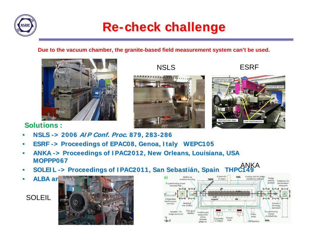
ReRe--check challengecheck challenge
Due to the vacuum chamber, the granite-based field measurement system can’t be used.
Solutions : Solutions : •• NSLS NSLS --> > 2006 2006 AIP Conf. ProcAIP Conf. Proc. 879, 283. 879, 283--286286•• ESRF ESRF --> Proceedings of EPAC08, Genoa, Italy WEPC105> Proceedings of EPAC08, Genoa, Italy WEPC105•• ANKA ANKA --> Proceedings of IPAC2012, New Orleans, Louisiana, USA > Proceedings of IPAC2012, New Orleans, Louisiana, USA
MOPPP067MOPPP067•• SOLEIL SOLEIL --> Proceedings of IPAC2011, San Sebasti> Proceedings of IPAC2011, San Sebastiáán, Spain THPC149n, Spain THPC149•• ALBA and many others ALBA and many others
SOLEIL
ESRF
ANKA
NSLS
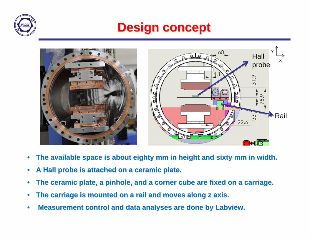
Design conceptDesign concept
Rail
Hall probe
X
Y
•• The available space is about eighty mm in height and sixty mm inThe available space is about eighty mm in height and sixty mm in width. width.
•• A Hall probe is attached on a ceramic plate. A Hall probe is attached on a ceramic plate.
•• The ceramic plate, a pinhole, and a corner cube are fixed on a cThe ceramic plate, a pinhole, and a corner cube are fixed on a carriage.arriage.
•• The carriage is mounted on a rail and moves along z axis.The carriage is mounted on a rail and moves along z axis.
•• Measurement control and data analyses are done by Labview. Measurement control and data analyses are done by Labview.
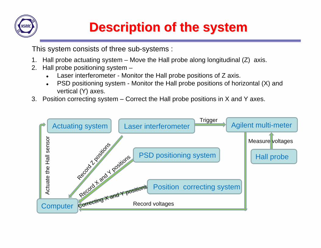
1. Hall probe actuating system – Move the Hall probe along longitudinal (Z) axis.2. Hall probe positioning system –
Laser interferometer - Monitor the Hall probe positions of Z axis. PSD positioning system - Monitor the Hall probe positions of horizontal (X) and
vertical (Y) axes.3. Position correcting system – Correct the Hall probe positions in X and Y axes.
This system consists of three sub-systems :
Description of the systemDescription of the system
Actuating system
Position correcting system
Computer
Hall probe
Laser interferometer Agilent multi-meter
PSD positioning system
Recor
d Z po
sition
s
Record X and Y positions
Trigger
Correcting X and Y positions
Measure voltages
Record voltages
Act
uate
the
Hal
l sen
sor
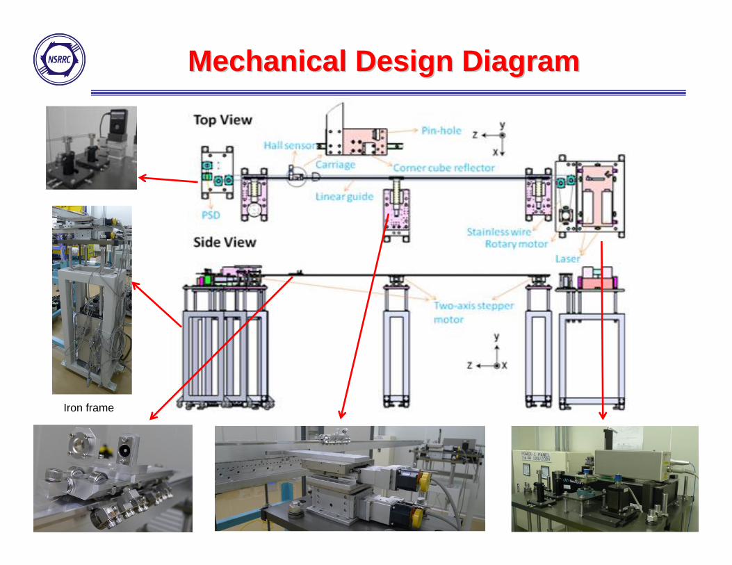
Mechanical Design DiagramMechanical Design Diagram
Iron frame

Hall sensor actuation systemHall sensor actuation system
Rotary motor
Hall sensor positions monitoring and correcting system are needed to correct the deviations.

Carriage and railCarriage and rail
Pin-hole
Corner cube
Ceramic plate
Rail
All components are non-magnetic and compatible used in high vacuum enviroment.
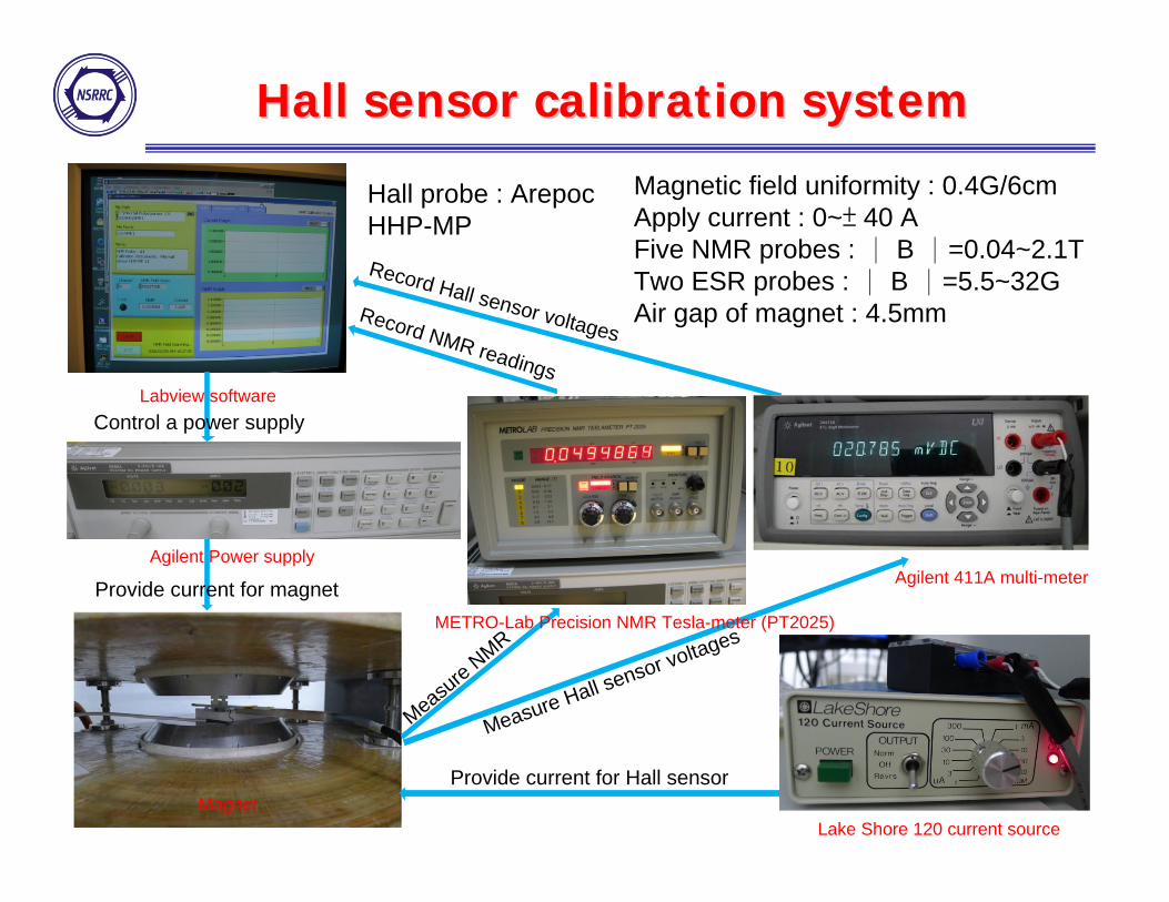
Hall sensor calibration systemHall sensor calibration system
Magnetic field uniformity : 0.4G/6cmApply current : 0~± 40 A Five NMR probes : | B |=0.04~2.1TTwo ESR probes : | B |=5.5~32GAir gap of magnet : 4.5mm
Lake Shore 120 current source
Agilent 411A multi-meter
Labview software
Magnet
Agilent Power supply
Provide current for Hall sensor
Control a power supply
Provide current for magnet
Record NMR readings
Record Hall sensor voltages
Measure Hall sensor voltages
Measure NMR METRO-Lab Precision NMR Tesla-meter (PT2025)
Hall probe : Arepoc HHP-MP
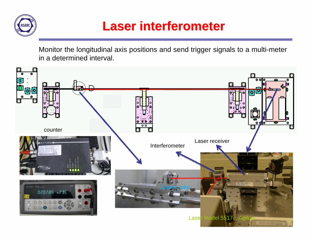
Laser interferometer Laser interferometer
Laser receiver
Corner cube
Interferometer
Monitor the longitudinal axis positions and send trigger signals to a multi-meter in a determined interval.
Laser Model 5517c, Agilent
counter

Position Sensitive Device
PSD positioning systemPSD positioning system
LaserPinhole
Monitor the X and Y positions of the Hall probe.

Position correcting systemPosition correcting system
X
Y
Z
X
Y
Correcting the X and Y axes positionsMotor movement resolution :Motor movement resolution :1 1 μμm in x axism in x axis0.5 0.5 μμm in y axism in y axis
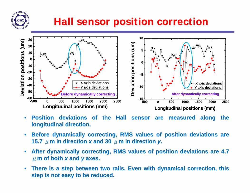
Hall sensor position correctionHall sensor position correction
-500 0 500 1000 1500 2000 2500-60
-50
-40
-30
-20
-10
0
10
20
30
Before dynamically correcting
Dev
iatio
n po
sitio
ns (u
m)
Longitudinal positions (mm)
X axis deviations Y axis deviations
-500 0 500 1000 1500 2000 2500-15
-10
-5
0
5
10
After dynamically correcting
Dev
iatio
n po
sitio
ns (u
m)
Longitudinal positions (mm)
X axis deviationsY axis deviations
•• PositionPosition deviations of the Hall sensor are measured along the deviations of the Hall sensor are measured along the longitudinal direction. longitudinal direction.
•• Before dynamically correcting, RMS values of position deviationsBefore dynamically correcting, RMS values of position deviations are are 15.7 15.7 μμm in direction m in direction xx and 30 and 30 μμm in direction m in direction yy..
•• After dynamically correcting, RMS values of position deviations After dynamically correcting, RMS values of position deviations are 4.7 are 4.7 μμm of both m of both xx and and y y axes.axes.
•• There is a step between two rails. Even with dynamical correctioThere is a step between two rails. Even with dynamical correction, this n, this step is not easy to be reduced. step is not easy to be reduced.

System test resultsSystem test results
Measure a test array six times in the same condition.
dBpeak/B 0.03%
-0.4
-0.3
-0.2
-0.1
0.0
0.1
0.2
0.3
0.4 1st 2nd 3rd 4th 5th 6th
On
axis
mag
netic
fiel
d (T
)
250 500 750 1000 1250 1500Longitudinal position (mm)
STD of Phase error RMS=0.15 degree
Moving speed : V=1 mm/sMoving speed : V=1 mm/sMeasuring interval : 0.5mmMeasuring interval : 0.5mm
-50
-40
-30
-20
-10
0
10
20
30
1st 2nd 3rd 4th 5th 6th
Pole Number
Phas
e Er
ror (
degr
ee)
0 5 10 15 20 25

Installed in IU22Installed in IU22--2m2m
It takes about 3 days to set up It takes about 3 days to set up the system and align the laser the system and align the laser beams. beams.
End chambers are removed End chambers are removed and the view port should be and the view port should be open. The four NEG pumps are open. The four NEG pumps are also removed to make the also removed to make the alignment easier. alignment easier.
End chamber
view port
NEG pump
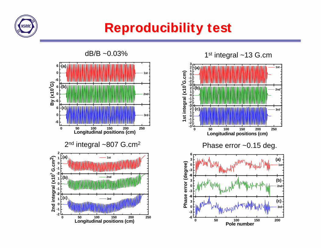
Reproducibility test Reproducibility test
-6
0
6
1st
By
(x10
3 G)
-6
0
6
2nd
0 50 100 150 200 250
-6
0
6
(c)
(b)
(a)
Longitudinal positions (cm)
3rd
-3-2-10123
1st
1st i
nteg
ral (
x103 G
.cm
)
-3-2-10123
2nd
0 50 100 150 200 250-3-2-10123
(c)
(b)
(a)
Longitudinal positions (cm)
3rd
-2-1012
1st
2nd
inte
gral
(x10
3 G.c
m2 )
-2-1012
2nd
0 50 100 150 200 250-2-1012
(c)
(b)
(a)
Longitudinal positions (cm)
3rd
-6-3036
1st
Phas
e er
ror (
degr
ee)
-6-3036
2nd
0 50 100 150 200-6-3036
(c)
(b)
(a)
Pole number
3rd
2nd integral ~807 G.cm2
1st integral ~13 G.cmdB/B ~0.03%
Phase error ~0.15 deg.
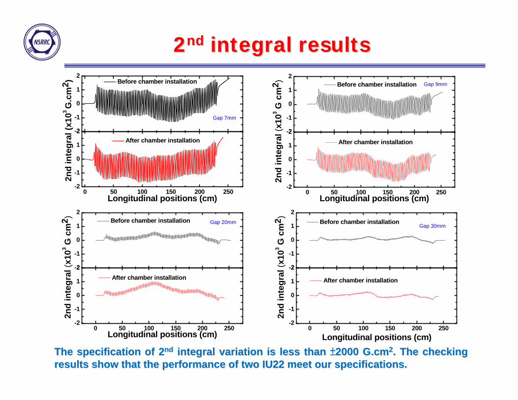
22ndnd integral resultsintegral results
The specification of 2The specification of 2ndnd integral variation is less than integral variation is less than ±±2000 G.cm2000 G.cm22. The checking . The checking results show that the performance of two IU22 meet our specificaresults show that the performance of two IU22 meet our specifications.tions.
-2
-1
0
1
2
Before chamber installation
2nd
inte
gral
(x10
3 G
.cm
2 )
0 50 100 150 200 250-2
-1
0
1
2
Longitudinal positions (cm)
After chamber installation
Gap 7mm
-2
-1
0
1
2
Before chamber installation
2nd
inte
gral
(x10
3 G c
m2 )
0 50 100 150 200 250-2
-1
0
1
2 After chamber installation
Longitudinal positions (cm)
Gap 9mm
-2
-1
0
1
2
Before chamber installation
2nd
inte
gral
(x10
3 G c
m2 )
0 50 100 150 200 250-2
-1
0
1
2
Gap 20mm
Longitudinal positions (cm)
After chamber installation-2
-1
0
1
2
Gap 30mm Before chamber installation
2nd
inte
gral
(x10
3 G c
m2 )
0 50 100 150 200 250-2
-1
0
1
2
Longitudinal positions (cm)
After chamber installation

Phase error resultsPhase error results
0 50 100 150 200
-6
-4
-2
0
2
4
6
Gap 7mm
Before chamber installation After chamber installation
Phas
e er
ror (
degr
ee)
Pole number0 50 100 150 200
-6
-4
-2
0
2
4
6
Gap 9mm
Before chamber installation After chamber installation
Phas
e er
ror (
degr
ee)
Pole number
0 50 100 150 200-1.0
-0.5
0.0
0.5
1.0
Gap 20mm
Before chamber installation After chamber installation
Phas
e er
ror (
degr
ee)
Pole number0 50 100 150 200
-1.0
-0.5
0.0
0.5
1.0 Before chamber installation After chamber installation Gap 30mm
Phas
e er
ror (
degr
ee)
Pole numberThe specifications of phase error r.m.s values are less than 3 dThe specifications of phase error r.m.s values are less than 3 degrees at all egrees at all gaps.gaps.The phase error differences may result from the magnet array gapThe phase error differences may result from the magnet array gap offset and offset and t d i bltaper during reassembly

Measurement results comparisonMeasurement results comparison
0 5 10 15 20 25 30 35 40 45 50 550.0
0.5
1.0
1.5
2.0
2.5
3.0
Phas
e Er
ror (
deg.
)
Gap (mm)
Before chamber installation After chamber installation
0 5 10 15 20 25 30 35 40 45 50 55
0.00
0.25
0.50
0.75
1.00
1.25
By
peak
(T)
Gap (mm)
Before chamber installation After chamber installation
Peak fields at different gaps Phase error at different gaps
•• Peak fields have negligible changes. Peak fields have negligible changes.
•• After chamber installation, the R.M.S values of phase error at After chamber installation, the R.M.S values of phase error at different gaps become a little worse, but they are still satisfidifferent gaps become a little worse, but they are still satisfied ed with our specifications, less than 3 degrees. with our specifications, less than 3 degrees.
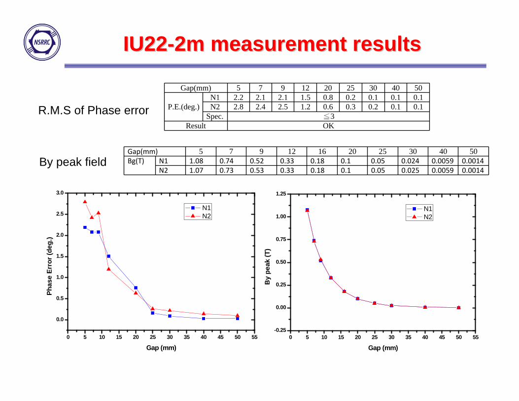
Gap(mm) 5 7 9 12 20 25 30 40 50
P.E.(deg.)N1 2.2 2.1 2.1 1.5 0.8 0.2 0.1 0.1 0.1N2 2.8 2.4 2.5 1.2 0.6 0.3 0.2 0.1 0.1
Spec. ≦3Result OK
R.M.S of Phase error
By peak field
IU22IU22--2m2m measurement resultsmeasurement results
Gap(mm) 5 7 9 12 16 20 25 30 40 50Bg(T) N1 1.08 0.74 0.52 0.33 0.18 0.1 0.05 0.024 0.0059 0.0014
N2 1.07 0.73 0.53 0.33 0.18 0.1 0.05 0.025 0.0059 0.0014
0 5 10 15 20 25 30 35 40 45 50 55-0.25
0.00
0.25
0.50
0.75
1.00
1.25
By
peak
(T)
Gap (mm)
N1 N2
0 5 10 15 20 25 30 35 40 45 50 55
0.0
0.5
1.0
1.5
2.0
2.5
3.0
Phas
e Er
ror (
deg.
)
Gap (mm)
N1 N2
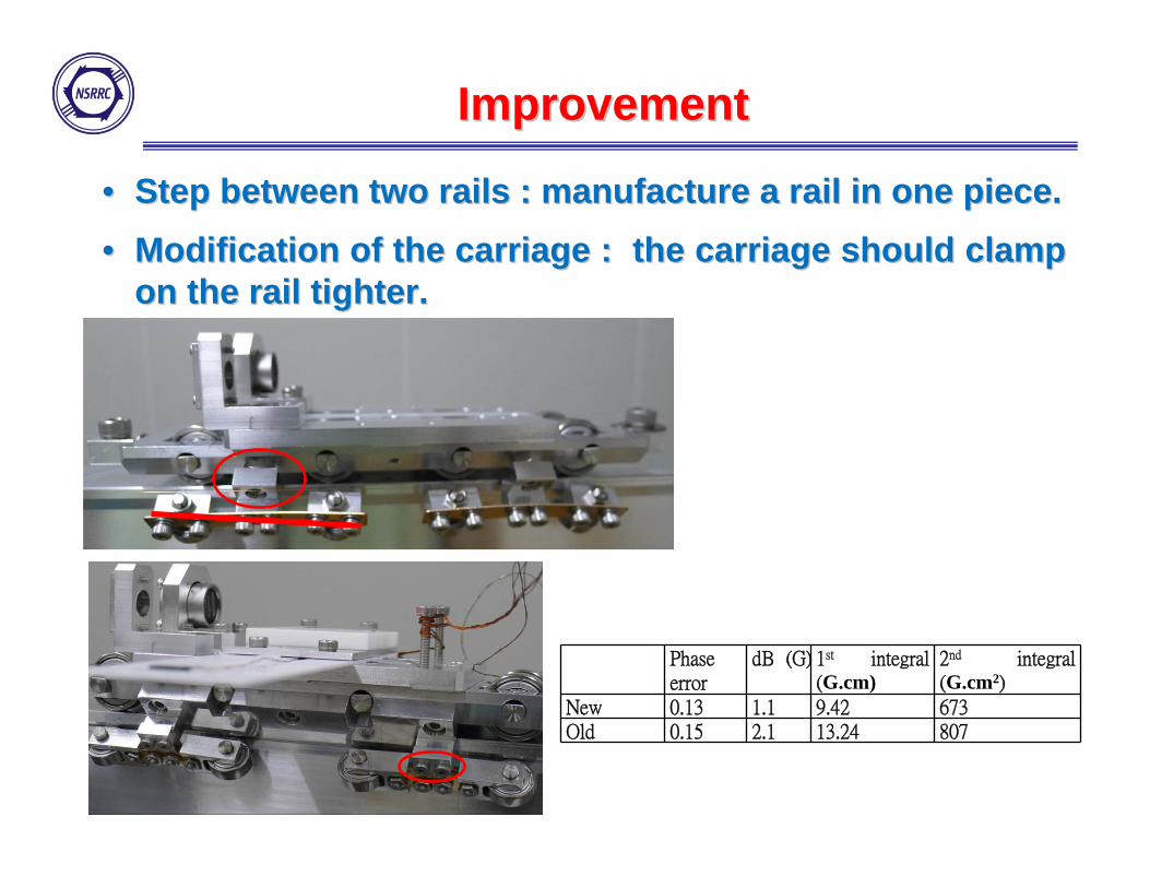
ImprovementImprovement
•• Step between two rails : manufacture a rail in one piece. Step between two rails : manufacture a rail in one piece. •• Modification of the carriage : the carriage should clamp Modification of the carriage : the carriage should clamp
on the rail tighter. on the rail tighter.
Phase error
dB (G) 1st integral (G.cm)
2nd integral (G.cm2)
New 0.13 1.1 9.42 673Old 0.15 2.1 13.24 807
SummarySummary
• Two IU22-2m are designed at NSRRC and fabricated by Hitachi Metal in Japan.
• We developed a system to measure the magnetic field performance in a vacuum chamber to check these IUs after there were delivered to Taiwan.
• Although there are small differences after the vacuum chamber assembly, the magnetic performances are still within our specifications.
• This system is modified to measure the incoming IU22-3m.
• In the future, this system will be further improved to do measurement in vacuum and

Thanks for your Thanks for your attentionattention


