Using Delcam Powermill Written by: John Eberhart & Trevor Williams DM Lab Tutorial Powermill is a sophistical tool path generating software. This tutorial will walk you through the steps of creating a basic, 3-axis vertical roughing tool path for milling in Powermill, starting with a 3D model in Rhino. We assume in this tutorial that you’ll be running your tool path on the robot, but the majority of what follows can be applied for jobs running on the other mills as well; the main principles are the same. Later tutorials will cover multi-axis milling which is specific to the robot. MILLING IS NOT AN EXACT SCIENCE Tool pathing and cutting on the mills, and especially on the robot, is not a matter of simply plugging in numbers and walking away. The consistency of materials, even the same type of materials, will vary, bits will get dull, and what cuts perfectly on one material with particular settings will not necessarily cut the same on another material. It’s essential that you consult with the DM Staff and Shop Personnel as well as refer to posted guidelines. Do not simply guess at settings such as speeds and feeds and hope for the best. Your attention to what you’re doing and your comprehension of the information in this tutorial are the key to safe and successful milling. Setting up the correct origin for your model and setting the correct units It is important to setup the correct origin of your model. The robot will record a base point. That base point is the same point as the model origin. You need to locate the model to be milled BELOW the XY ground plane and in the POSITIVE XY quadrant. Below Ground plane Y X In the Positive X and Y Quadrant
Transcript
Using Delcam PowermillWritten by: John Eberhart & Trevor WilliamsDM Lab Tutorial
Powermill is a sophistical tool path generating software. This tutorial will walk you through the steps of creating a basic, 3-axis vertical roughing tool path for milling in Powermill, starting with a 3D model in Rhino. We assume in this tutorial that you’ll be running your tool path on the robot, but the majority of what follows can be applied for jobs running on the other mills as well; the main principles are the same. Later tutorials will cover multi-axis milling which is specifi c to the robot.
MILLING IS NOT AN EXACT SCIENCE
Tool pathing and cutting on the mills, and especially on the robot, is not a matter of simply plugging in numbers and walking away. The consistency of materials, even the same type of materials, will vary, bits will get dull, and what cuts perfectly on one material with particular settings will not necessarily cut the same on another material. It’s essential that you consult with the DM Staff and Shop Personnel as well as refer to posted guidelines. Do not simply guess at settings such as speeds and feeds and hope for the best.
Your attention to what you’re doing and your comprehension of the information in this tutorial are the key to safe and successful milling.
Setting up the correct origin for your model and setting the correct units
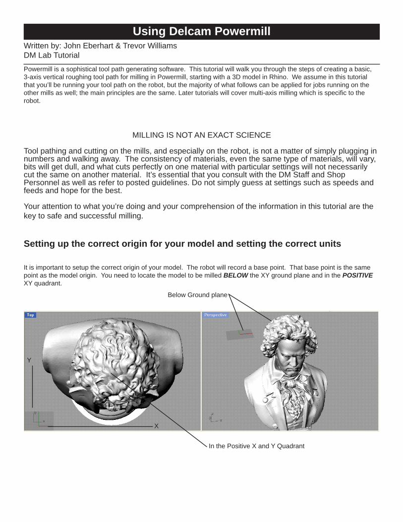
It is important to setup the correct origin of your model. The robot will record a base point. That base point is the same point as the model origin. You need to locate the model to be milled BELOW the XY ground plane and in the POSITIVE XY quadrant.
Below Ground plane
Y
X
In the Positive X and Y Quadrant
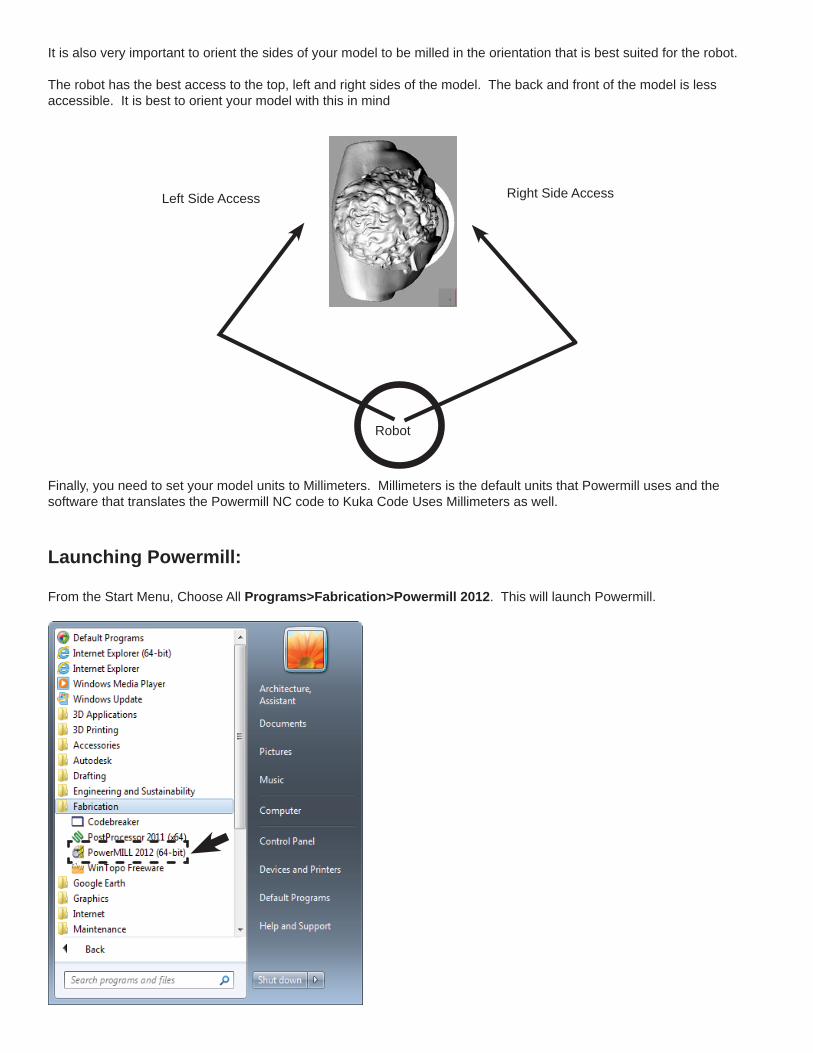
Robot
Right Side AccessLeft Side Access
It is also very important to orient the sides of your model to be milled in the orientation that is best suited for the robot.
The robot has the best access to the top, left and right sides of the model. The back and front of the model is less accessible. It is best to orient your model with this in mind
Finally, you need to set your model units to Millimeters. Millimeters is the default units that Powermill uses and the software that translates the Powermill NC code to Kuka Code Uses Millimeters as well.
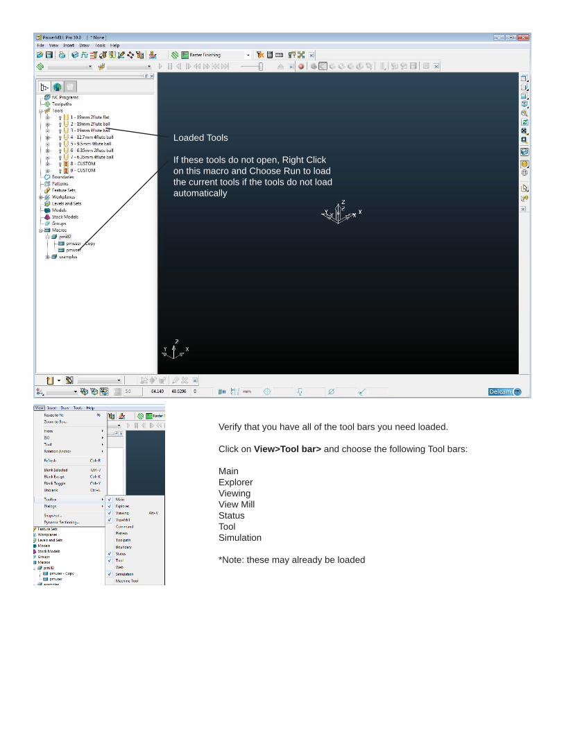
Launching Powermill:
From the Start Menu, Choose All Programs>Fabrication>Powermill 2012. This will launch Powermill.
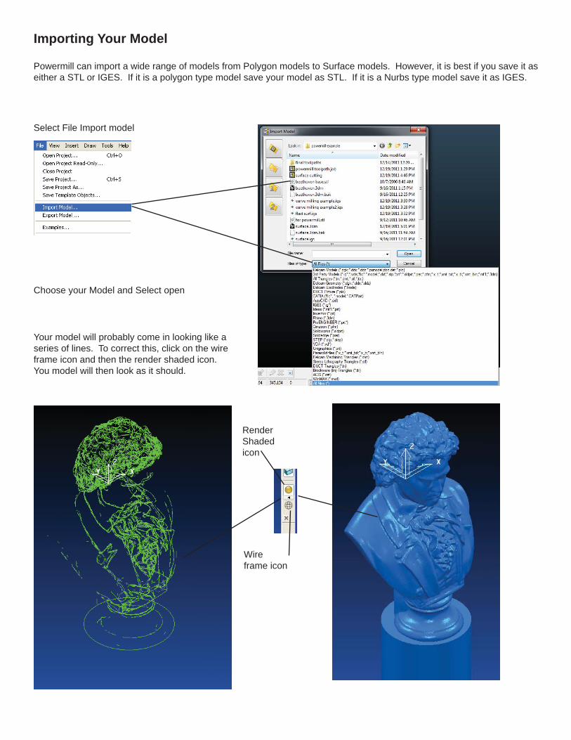
Loaded Tools
If these tools do not open, Right Click on this macro and Choose Run to load the current tools if the tools do not load automatically
Verify that you have all of the tool bars you need loaded.
Click on View>Tool bar> and choose the following Tool bars:
MainExplorerViewingView MillStatusToolSimulation
*Note: these may already be loaded
Select File Import model
Choose your Model and Select open
Your model will probably come in looking like a series of lines. To correct this, click on the wire frame icon and then the render shaded icon. You model will then look as it should.
Wire frame icon
Render Shaded icon
Powermill can import a wide range of models from Polygon models to Surface models. However, it is best if you save it as either a STL or IGES. If it is a polygon type model save your model as STL. If it is a Nurbs type model save it as IGES.
Importing Your Model
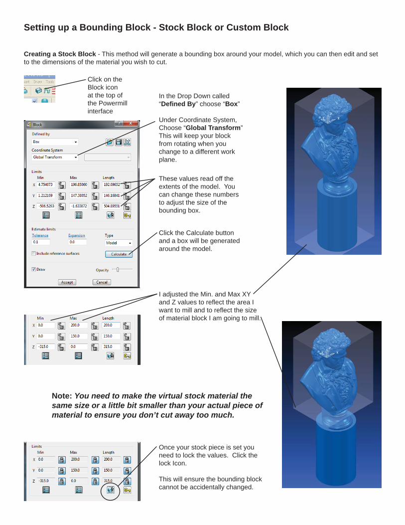
Setting up a Bounding Block - Stock Block or Custom Block
Click on the Block icon at the top of the Powermill interface
Click the Calculate button and a box will be generated around the model.
These values read off the extents of the model. You can change these numbers to adjust the size of the bounding box.
I adjusted the Min. and Max XY and Z values to refl ect the area I want to mill and to refl ect the size of material block I am going to mill.
Note: You need to make the virtual stock material the same size or a little bit smaller than your actual piece of material to ensure you don’t cut away too much.
Once your stock piece is set you need to lock the values. Click the lock Icon.
This will ensure the bounding block cannot be accidentally changed.
Creating a Stock Block - This method will generate a bounding box around your model, which you can then edit and set to the dimensions of the material you wish to cut.
In the Drop Down called “Defi ned By” choose “Box”
Under Coordinate System, Choose “Global Transform” This will keep your block from rotating when you change to a different work plane.
Click on the Block icon at the top of the Powermill interface
Creating a Custom Block - This method will allow you to load a 3D model that simulates a custom shaped stock piece. This method takes a little more time to complete, but can save you hours of “Cutting Air” down the road.
In the Drop Down called “Defi ned By” choose “Triangles”
Click the fi le icon to load the block model.
Browse to the custom block model and load it.
You will see your custom block model appear around the model you wish to cut.
Under Coordinate System, Choose “Global Transform” This will keep your block from rotating when you change to a different work plane.
In your original modeling program, build the custom block around your object. In this case you see the original Beethoven model with some simple boxes built around the object. These boxes will become my bounding box.
Select the boxes and choose File>Export Selected.
Use STL as the fi le type and save the bounding box model.
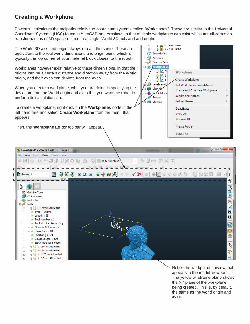
Creating a Workplane
Powermill calculates the toolpaths relative to coordinate systems called “Workplanes”. These are similar to the Universal Coordinate Systems (UCS) found in AutoCAD and Archicad, in that multiple workplanes can exist which are all cartesian transformations of 3D space related to a single, World 3D axis and and origin.
The World 3D axis and origin always remain the same. These are equivalent to the real world dimensions and origin point, which is typically the top corner of your material block closest to the robot.
Workplanes however exist relative to these dimenisions, in that their origins can be a certain distance and direction away from the World origin, and their axes can deviate from the axes.
When you create a workplane, what you are doing is specifying the deviation from the World origin and axes that you want the robot to perform its calculations in.
To create a workplane, right-click on the Workplanes node in the left hand tree and select Create Workplane from the menu that appears.
Then, the Workplane Editor toolbar will appear.
Notice the workplane preview that appears in the model viewport. The yellow wireframe plane shows the XY plane of the workplane being created. This is, by default, the same as the world origin and axes.
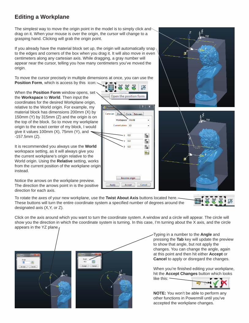
Editing a Workplane
The simplest way to move the origin point in the model is to simply click and drag on it. When your mouse is over the origin, the cursor will change to a grasping hand. Clicking will grab the origin point.
If you already have the material block set up, the origin will automatically snap to the edges and corners of the box when you drag it. It will also move in even centimeters along any cartesian axis. While dragging, a gray number will appear near the cursor, telling you how many centimeters you’ve moved the origin.
To move the cursor precisely in multiple dimensions at once, you can use the Position Form, which is access by this icon:
When the Position Form window opens, set the Workspace to World. Then input thecoordinates for the desired Workplane origin, relative to the World origin. For example, my material block has dimensions 200mm (X) by 150mm (Y) by 315mm (Z) and the origin is on the top of the block. So to move my workplane origin to the exact center of my block, I would give it values 100mm (X), 75mm (Y), and -157.5mm (Z).
It is recommended you always use the World workspace setting, as it will always give you the current workplane’s origin relative to the World origin. Using the Relative setting, works from the current position of the workplane origin instead.
Notice the arrows on the workplane preview. The direction the arrows point in is the positive direction for each axis.
To rotate the axes of your new workplane, use the Twist About Axis buttons located here. These buttons will turn the entire coordinate system a specifi ed number of degrees around the designated axis (X,Y, or Z).
Click on the axis around which you want to turn the coordinate system. A window and a circle will appear. The circle will show you the direction in which the coordinate system is turning. In this case, I’m turning about the X axis, and the circle appears in the YZ plane.
Typing in a number to the Angle and pressing the Tab key will update the preview to show that angle, but not apply the changes. You can change the angle, again at this point and then hit either Accept or Cancel to apply or disregard the changes.
When you’re fi nished editing your workplane, hit the Accept Changes button which looks like this:
NOTE: You won’t be able to perform any other functions in Powermill until you’ve accepted the workplane changes.
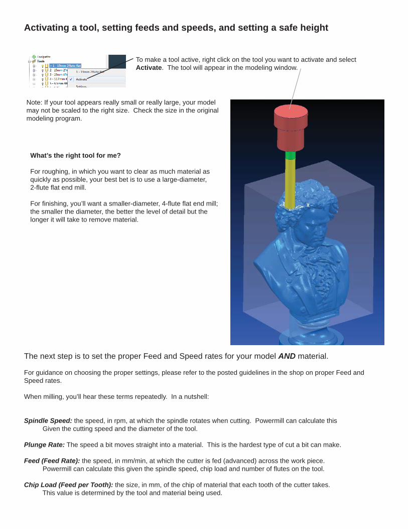
Activating a tool, setting feeds and speeds, and setting a safe height
To make a tool active, right click on the tool you want to activate and select Activate. The tool will appear in the modeling window.
Note: If your tool appears really small or really large, your model may not be scaled to the right size. Check the size in the original modeling program.
The next step is to set the proper Feed and Speed rates for your model AND material.
For guidance on choosing the proper settings, please refer to the posted guidelines in the shop on proper Feed and Speed rates.
When milling, you’ll hear these terms repeatedly. In a nutshell:
Spindle Speed: the speed, in rpm, at which the spindle rotates when cutting. Powermill can calculate this Given the cutting speed and the diameter of the tool.
Plunge Rate: The speed a bit moves straight into a material. This is the hardest type of cut a bit can make.
Feed (Feed Rate): the speed, in mm/min, at which the cutter is fed (advanced) across the work piece. Powermill can calculate this given the spindle speed, chip load and number of fl utes on the tool.
Chip Load (Feed per Tooth): the size, in mm, of the chip of material that each tooth of the cutter takes. This value is determined by the tool and material being used.
What’s the right tool for me?
For roughing, in which you want to clear as much material as quickly as possible, your best bet is to use a large-diameter, 2-fl ute fl at end mill.
For fi nishing, you’ll want a smaller-diameter, 4-fl ute fl at end mill; the smaller the diameter, the better the level of detail but the longer it will take to remove material.
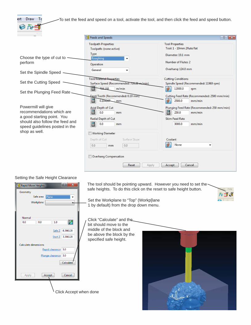
The tool should be pointing upward. However you need to set the safe heights. To do this click on the reset to safe height button.
Click “Calculate” and the bit should move to the middle of the block and be above the block by the specifi ed safe height.
Click Accept when done
To set the feed and speed on a tool, activate the tool, and then click the feed and speed button.
Choose the type of cut to perform
Set the Spindle Speed
Set the Cutting Speed
Set the Plunging Feed Rate
Powermill will give recommendations which are a good starting point. You should also follow the feed and speed guidelines posted in the shop as well.
Setting the Safe Height Clearance
Set the Workplane to “Top” (Workp[lane 1 by default) from the drop down menu.
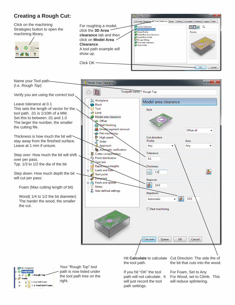
Creating a Rough Cut:Click on the machining Strategies button to open the machining library.
For roughing a model, click the 3D Area clearance tab and then click on Model Area Clearance.A tool path example will show up.
Click OK
Name your Tool path (I.e. Rough Top)
Verify you are using the correct tool
Leave tolerance at 0.1This sets the length of vector for the tool path. .01 is 1/10th of a MM.Set this to between .01 and 1.0The larger the number, the smaller the cutting fi le.
Thickness is how much the bit will stay away from the fi nished surface. Leave at 1 mm if unsure.
Step over: How much the bit will shift over per pass.Typ. 1/3 to 1/2 the dia of the bit
Step down: How much depth the bit will cut per pass:
Foam (Max cutting length of bit)
Wood( 1/4 to 1/2 the bit diameter) The harder the wood, the smaller the cut.
Hit Calculate to calculate the tool path.
If you hit “OK” the tool path will not calculate. It will just record the tool path settings.
Your “Rough Top” tool path is now listed under the tool path tree on the right.
Cut Direction: The side the of the bit that cuts into the wood.
For Foam, Set to Any For Wood, set to Climb. This will reduce splintering.
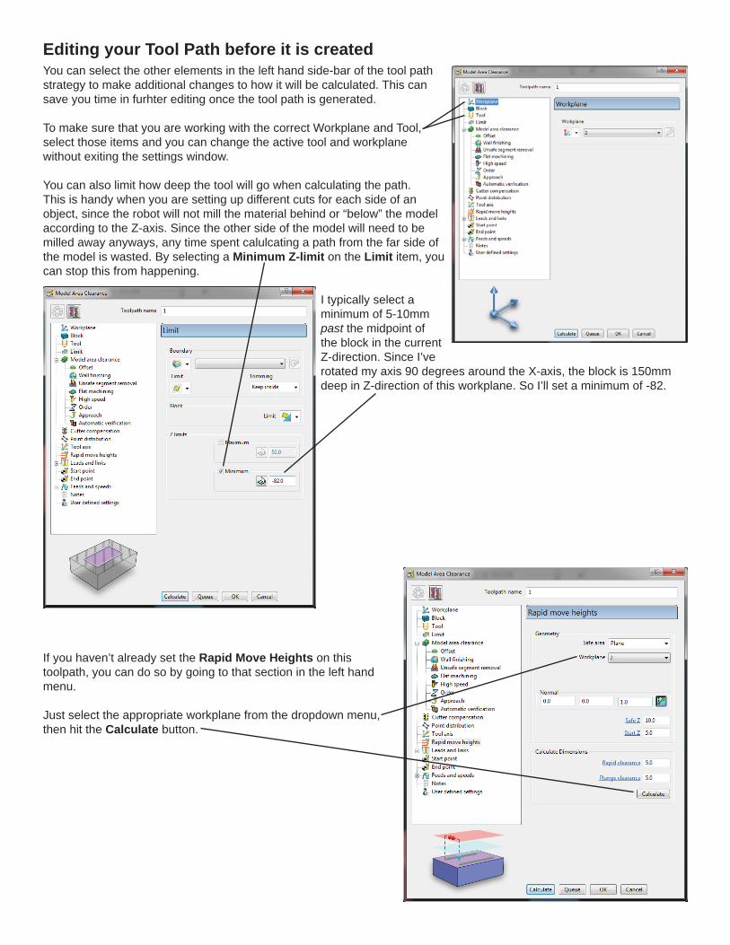
You can select the other elements in the left hand side-bar of the tool path strategy to make additional changes to how it will be calculated. This can save you time in furhter editing once the tool path is generated.
To make sure that you are working with the correct Workplane and Tool, select those items and you can change the active tool and workplane without exiting the settings window.
You can also limit how deep the tool will go when calculating the path. This is handy when you are setting up different cuts for each side of an object, since the robot will not mill the material behind or “below” the model according to the Z-axis. Since the other side of the model will need to be milled away anyways, any time spent calulcating a path from the far side of the model is wasted. By selecting a Minimum Z-limit on the Limit item, you can stop this from happening.
I typically select a minimum of 5-10mm past the midpoint of the block in the current Z-direction. Since I’ve rotated my axis 90 degrees around the X-axis, the block is 150mm deep in Z-direction of this workplane. So I’ll set a minimum of -82.
If you haven’t already set the Rapid Move Heights on this toolpath, you can do so by going to that section in the left hand menu.
Just select the appropriate workplane from the dropdown menu, then hit the Calculate button.
Editing your Tool Path before it is created
Editing your Tool path after it is created
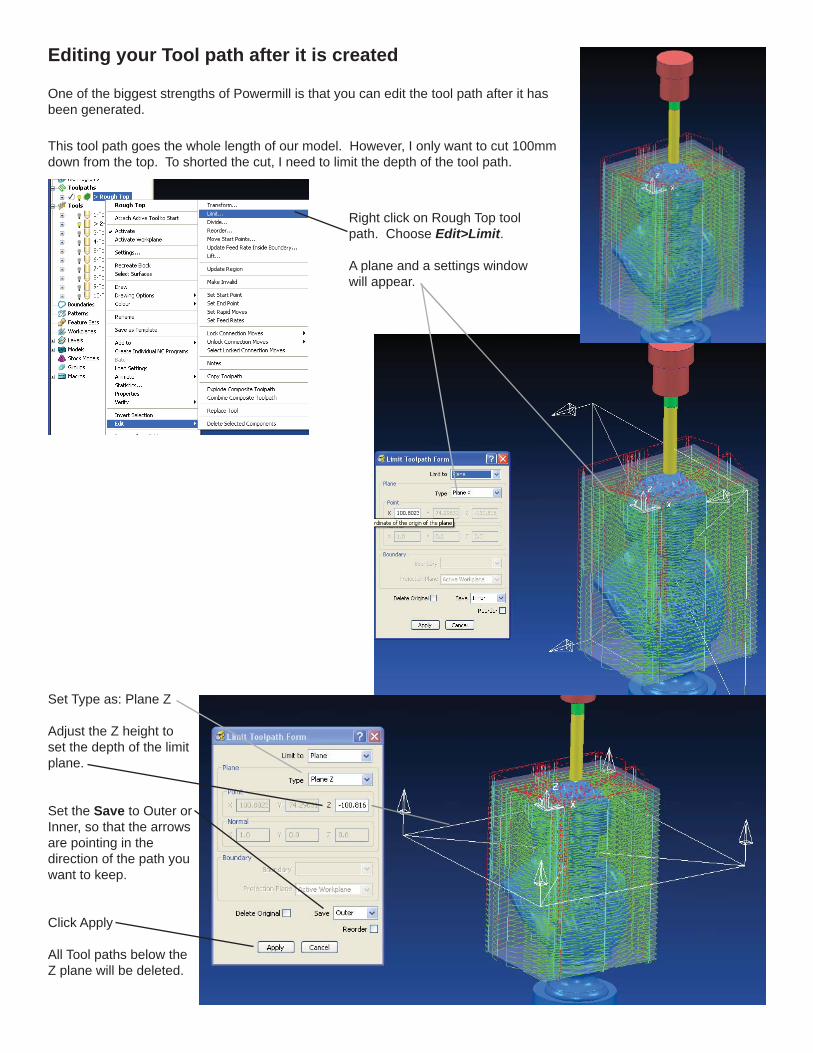
One of the biggest strengths of Powermill is that you can edit the tool path after it has been generated.
Right click on Rough Top tool path. Choose Edit>Limit.
A plane and a settings window will appear.
This tool path goes the whole length of our model. However, I only want to cut 100mm down from the top. To shorted the cut, I need to limit the depth of the tool path.
Set Type as: Plane Z
Adjust the Z height to set the depth of the limit plane.
Set the Save to Outer or Inner, so that the arrows are pointing in the direction of the path you want to keep.
Click Apply
All Tool paths below the Z plane will be deleted.
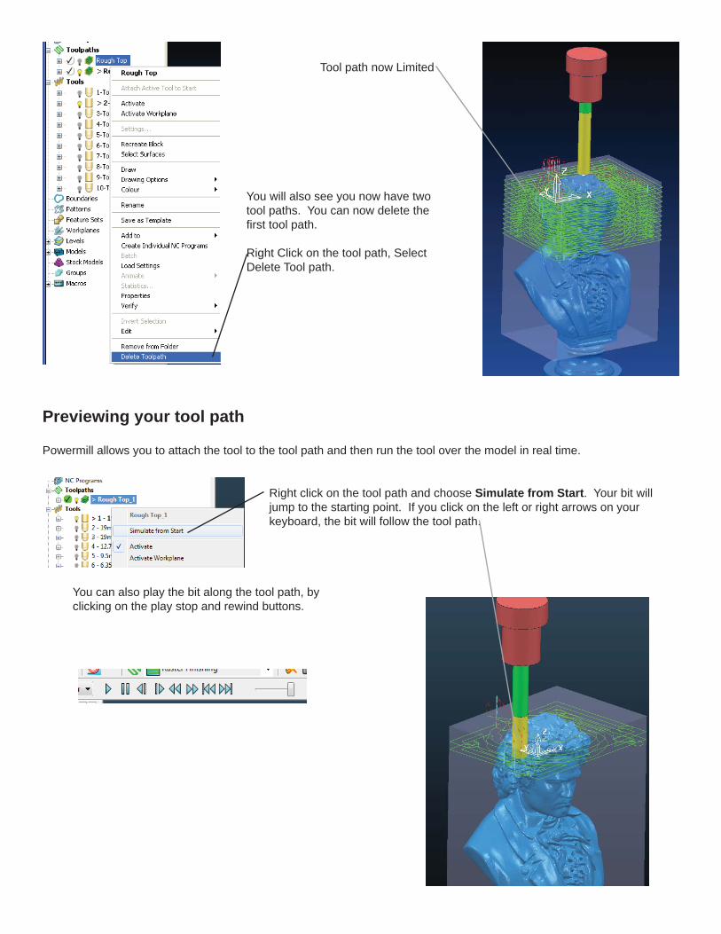
Tool path now Limited
You will also see you now have two tool paths. You can now delete the fi rst tool path.
Right Click on the tool path, Select Delete Tool path.
Previewing your tool path
Powermill allows you to attach the tool to the tool path and then run the tool over the model in real time.
Right click on the tool path and choose Simulate from Start. Your bit will jump to the starting point. If you click on the left or right arrows on your keyboard, the bit will follow the tool path.
You can also play the bit along the tool path, by clicking on the play stop and rewind buttons.
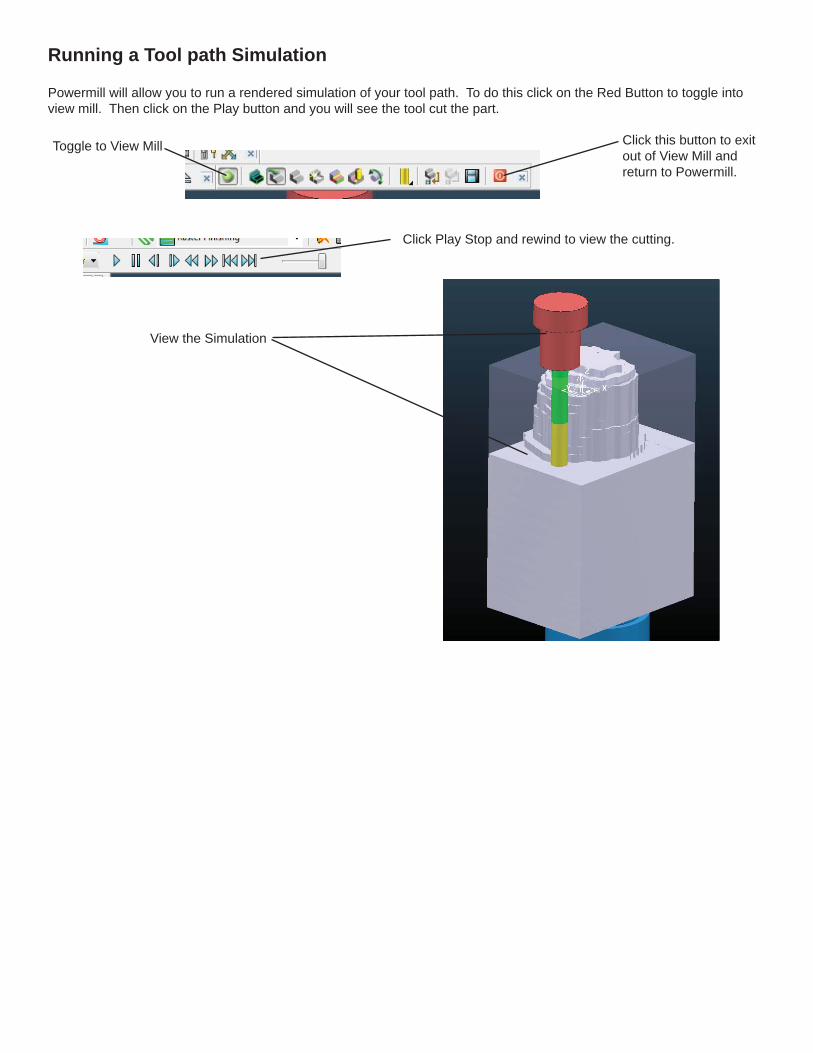
Running a Tool path Simulation
Powermill will allow you to run a rendered simulation of your tool path. To do this click on the Red Button to toggle into view mill. Then click on the Play button and you will see the tool cut the part.
Toggle to View Mill
Click Play Stop and rewind to view the cutting.
Click this button to exit out of View Mill and return to Powermill.
View the Simulation
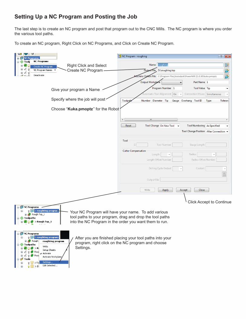
Setting Up a NC Program and Posting the Job
The last step is to create an NC program and post that program out to the CNC Mills. The NC program is where you order the various tool paths.
To create an NC program, Right Click on NC Programs, and Click on Create NC Program.
Right Click and Select Create NC Program
Give your program a Name
Specify where the job will post
Choose “Kuka.pmoptz ” for the Robot
Click Accept to Continue
Your NC Program will have your name. To add various tool paths to your program, drag and drop the tool paths into the NC Program in the order you want them to run.
After you are fi nished placing your tool paths into your program, right click on the NC program and choose Settings.
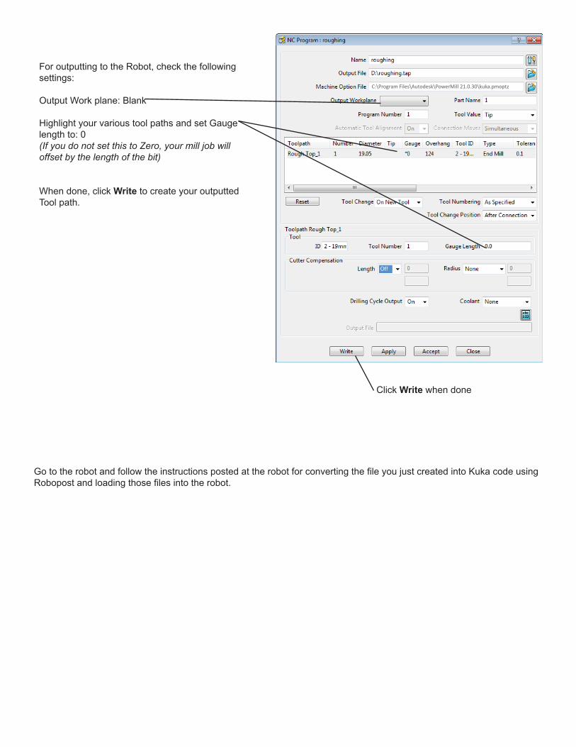
For outputting to the Robot, check the following settings:
Output Work plane: Blank
Highlight your various tool paths and set Gauge length to: 0 (If you do not set this to Zero, your mill job will offset by the length of the bit)
When done, click Write to create your outputted Tool path.
Click Write when done
Go to the robot and follow the instructions posted at the robot for converting the fi le you just created into Kuka code using Robopost and loading those fi les into the robot.