machine design, Vol.4(2012) No.3, ISSN 1821-1259 pp. 157-160 *Correspondence Author’s Address: University of Maribor, Faculty of Mechanical Engineering, Smetanova 17, 2000 Maribor, Slovenia, [email protected]Research paper USING LabVIEW SOFTWARE FOR DEVELOPMENT OF NEW DATA ACQUISITION SOFTWARE Marko REIBENSCHUH 1, * - Franc CUS 1 - Uros ZUPERL 1 1 University of Maribor, Faculty of Mechanical Engineering, Maribor, Slovenia Received (16.07.2012); Revised (06.09.2012); Accepted (12.09.2012) Abstract: LabVIEW enables programing and development of different interfaces for monitoring. Because of worldwide increasing demands for condition monitoring and demands to increase productivity, a new user interface for data acquisition is developed and applied to gather data and information during cutting. Other possibilities for implementing the method into production process are also researched. To monitor a high speed process, the use of high speed camera is inevitable.. This paper presents preliminary development, tests and result. Key words: Monitoring, Milling, Data Acquisition, LabVIEW 1. INTRODUCTION Programs developed for monitoring are no longer written in whole by the developer. Programs as C, C#, C++, Lisp and many others are complex to write and correct. LabVIEW has the advantage that many of the coding is already grouped into blocks, which already have a certain function. In recent years there has been a minor setback in development of new acquisition techniques and software. Most authors use existing techniques and programs which they rewrite and implement methods from other scientific fields. Some author use intelligent methods to optimize, predict, gather information and data, others rely on hardware to measure and gather data. A decision was made to rewrite an existing system for measurements and gathering data with an additional system. In the field of machining were everything constantly in motion the options for data gathering and applying new techniques are endless. But still there are some restrictions coupled on the acquired values. These restrictions are coupled to the hardware equipment used for measuring and gathering data. The equipment used for specific measurements and data acquisition is very specific, expensive and hard to apply. A large amount of hardware was evaluated for the use in the new system. The other advantage of using LabVIEW is its ability to use the software with any given hardware. Some of the evaluated hardware is visual sensors and cameras, sound sensor, vibration sensors and heat sensors. The main representatives in this division were evaluated after following criteria: considering the ability of optional adjusting the parameters and, applicability into other applications. Machining processes are time and resource demanding. The procedure itself runs at high speeds, under great thermal and physical loads, therefore the equipment must withstand the rising demands of wear and tear. Today’s cutting speeds depend on the speed of the main spindle. In some cases the spindle can rotate at 50000 rpm in specific cases even to 100000 rpm. Cameras, such as thermal cameras give information on how the temperatures are arranged in the material and which parts are under larger load. The main disadvantage of using the thermal camera is the insufficient information about the physical properties of material - the work piece material or the material of the cutting tool. This information is essential for correct evaluation of gathered data and possible numerical simulations. The manufacturer of the cutting tool or the work piece material does not give away that information because of protection of interests. Sound – vibration sensor give good results but they are very sensitive to the environmental influence. The slightest disturbance causes incorrect measurements and the gathered data can be discarded. In a working environment, there are a lot of disturbances from other machines. With the use of special filters these disturbances can eventually be filtered out and the signal cleared. Even if we manage to get a clear signal with no distortions, the state of the tool or work piece is still unknown. The state of it must be determined with the use of other measurement equipment. The use of a high speed camera reduces some disadvantages of previous mentioned equipment (thermal camera and sound sensors). Its work is similar to the work of an operator behind his machine. The operator listens and visually inspects the errors and if necessary adjusts the cutting settings. Therefore a decision was made to begin developing and testing a system which includes a colour high speed camera and a user interface developed in LabVIEW. 2. GATHERING EQUIPMENT AND MATERIAL After the decision was made what system to develop, the high speed camera was purchased. It enables a maximum speed of 65 frames per second (fps). For comparison, the human eye detects up to 20 fps. The resolution of the captured images can range up to 640 x 480 pixels. For dark conditions it also has a built in trigger for additional
Transcript
machine design, Vol.4(2012) No.3, ISSN 1821-1259 pp. 157-160
*Correspondence Author’s Address: University of Maribor, Faculty of Mechanical Engineering, Smetanova 17, 2000 Maribor, Slovenia, [email protected]
Research paper USING LabVIEW SOFTWARE FOR DEVELOPMENT OF NEW DATA ACQUISITION SOFTWARE Marko REIBENSCHUH1, * - Franc CUS1 - Uros ZUPERL1 1 University of Maribor, Faculty of Mechanical Engineering, Maribor, Slovenia
Received (16.07.2012); Revised (06.09.2012); Accepted (12.09.2012) Abstract: LabVIEW enables programing and development of different interfaces for monitoring. Because of worldwide increasing demands for condition monitoring and demands to increase productivity, a new user interface for data acquisition is developed and applied to gather data and information during cutting. Other possibilities for implementing the method into production process are also researched. To monitor a high speed process, the use of high speed camera is inevitable.. This paper presents preliminary development, tests and result. Key words: Monitoring, Milling, Data Acquisition, LabVIEW 1. INTRODUCTION Programs developed for monitoring are no longer written in whole by the developer. Programs as C, C#, C++, Lisp and many others are complex to write and correct. LabVIEW has the advantage that many of the coding is already grouped into blocks, which already have a certain function. In recent years there has been a minor setback in development of new acquisition techniques and software. Most authors use existing techniques and programs which they rewrite and implement methods from other scientific fields. Some author use intelligent methods to optimize, predict, gather information and data, others rely on hardware to measure and gather data. A decision was made to rewrite an existing system for measurements and gathering data with an additional system. In the field of machining were everything constantly in motion the options for data gathering and applying new techniques are endless. But still there are some restrictions coupled on the acquired values. These restrictions are coupled to the hardware equipment used for measuring and gathering data. The equipment used for specific measurements and data acquisition is very specific, expensive and hard to apply. A large amount of hardware was evaluated for the use in the new system. The other advantage of using LabVIEW is its ability to use the software with any given hardware. Some of the evaluated hardware is visual sensors and cameras, sound sensor, vibration sensors and heat sensors. The main representatives in this division were evaluated after following criteria:
considering the ability of optional adjusting the parameters and,
applicability into other applications. Machining processes are time and resource demanding. The procedure itself runs at high speeds, under great thermal and physical loads, therefore the equipment must withstand the rising demands of wear and tear. Today’s cutting speeds depend on the speed of the main spindle. In some cases the spindle can rotate at 50000 rpm in specific cases even to 100000 rpm. Cameras, such as thermal
cameras give information on how the temperatures are arranged in the material and which parts are under larger load. The main disadvantage of using the thermal camera is the insufficient information about the physical properties of material - the work piece material or the material of the cutting tool. This information is essential for correct evaluation of gathered data and possible numerical simulations. The manufacturer of the cutting tool or the work piece material does not give away that information because of protection of interests. Sound – vibration sensor give good results but they are very sensitive to the environmental influence. The slightest disturbance causes incorrect measurements and the gathered data can be discarded. In a working environment, there are a lot of disturbances from other machines. With the use of special filters these disturbances can eventually be filtered out and the signal cleared. Even if we manage to get a clear signal with no distortions, the state of the tool or work piece is still unknown. The state of it must be determined with the use of other measurement equipment. The use of a high speed camera reduces some disadvantages of previous mentioned equipment (thermal camera and sound sensors). Its work is similar to the work of an operator behind his machine. The operator listens and visually inspects the errors and if necessary adjusts the cutting settings. Therefore a decision was made to begin developing and testing a system which includes a colour high speed camera and a user interface developed in LabVIEW. 2. GATHERING EQUIPMENT AND
MATERIAL After the decision was made what system to develop, the high speed camera was purchased. It enables a maximum speed of 65 frames per second (fps). For comparison, the human eye detects up to 20 fps. The resolution of the captured images can range up to 640 x 480 pixels. For dark conditions it also has a built in trigger for additional
Marko Reibenschuh, Franc Cus, Uros Zuperl: Using LabVIEW Software for Development of New Data Acquisition Software; Machine Design, Vol.4(2012) No.3, ISSN 1821-1259; pp. 157-160
158
light source. A built in 1.6 GHz processor enables fast processing of gathered frames. The camera has also an IP67 protection rating, so that it can be also used in working conditions. To use such a camera a compromise must be done to satisfy the need for speed and the need for accuracy. For example, to determine the length of a chip, the scale can be bigger than 1 mm, but to observe the size of the tool, one must consider the tight tolerances during machining. Therefore the scale must be smaller. For 0.1 mm accuracy, the maximum observed window size at a resolution of 640 x 480 pixels is 21.3 x 16 mm. For an accuracy of 0.01 mm, the maximum search area would be 2.13 x 1.6 mm. For practical reasons this value is too small – the inflicted damage results in bigger deformations. Therefore the settings for the accuracy were set to 0.1 mm (100 µm). Use of such a small observed area is reasonable in micro milling, where the cutting tool is accordingly smaller. During the preliminary testing, the cutting speeds did not exceed 2000 rpm. At 2000 rpm, the tool rotates at a speed of 33.33 rotations per second. Depending on the camera settings, the acquired number of frames can vary. Options for number of frames can be set to the precise cutting speed or any other between 0.001 and 65. For practical reasons as monitoring and determining the tool position, respectively the position of the work piece, the settings were set to capture a frame on every full rotation. Meaning, that at a speed of 2000 rpm 2000 frames are taken. Because of the memory limitations from the camera, the camera can only capture and save 500 frames. Afterwards the buffer is full and it can no longer gather new frames. The buffer must be emptied and the gathering can proceed. If a lower cutting speed is chosen, more images can be gathered during one tool rotation. At 1950 rpm the tool and work piece can be captured 2 times – first one at the start position and the second frame after a 180° turn of the work piece. The use of the colour lens enables the spotting of colour deviations on the cutting tool tip or the chip. This option allows determining the thermal influence on the work piece and chip. In conclusion, this high speed camera enables different options of measurements:
Detection of parts bigger than 1 mm – detection area of 213 mm x 160 mm,
Detection of parts bigger than 0.1 mm – detection area of 21.3 mm x 16 mm,
Detection in colour variations – overheated cutting tool, chip or work piece,
Detection of every full rotation of the cutting tool at 3.900 rpm,
Detection of one or more rotations depending on the spindle speed.
Considering all options of detection and classification, a decision was made which settings to use and which features to monitor during the test. 3. PREPARATIONS FOR TESTING Before the tests were carried out, the connection between the computer and the camera needed to be established and also the new version of LabVIEW installed. Because the software is not fully compatible with the new version of Windows, there was a delay in connecting both of them.
A software update and some other changes in network settings were needed to get the connection running. The solution is not universal so here some improvisation is needed. The camera is connected via Ethernet port to the computer. One of the cameras feature is also its ability to function without a computer. Because it has a built in chip and a processor, a program can be uploaded. When the program is running it can take frames or overview a process autonomously by pre specified settings. In the tests, the camera was connected and ran over the only over the computer. The frames, Fig. 1, show the problem with illumination for the first test. Some corrections were needed and the external light had to be added. The second run shows more useable frames – the desired features are clearly visible. The gathered frames were uploaded to the computer and off line evaluated.
Fig.1. Poor lighting conditions – not suitable for further processing
num. 5 num. 10
num. 60 num. 90
num. 130 num. 170
num. 270 num. 290
Fig.2 Numbered frames gathered during the testing
Marko Reibenschuh, Franc Cus, Uros Zuperl: Using LabVIEW Software for Development of New Data Acquisition Software; Machine Design, Vol.4(2012) No.3, ISSN 1821-1259; pp. 157-160
159
Set of frames, Fig. 2, shows the conditions during drilling on a turning machine. The formation and development of the chip is clearly visible. The used work piece material was an Aluminium alloy with the designation AC 44, AC 62 and AC 66. For initial test monochrome frames were used. Monochrome frames were chosen because of two main reasons:
They are smaller in size, The Aluminium does not have such distinctive heat residues as steel – the colour changes were not noticed.
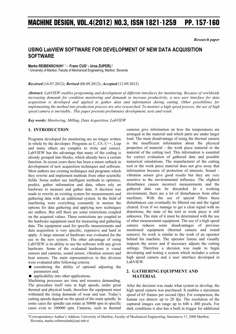
4. EVALUATION OF RESULTS Problems occurred because the mechanical properties of the Aluminium alloy. The chip formation was considerable but the chips at first did not break off. Without the camera this was impossible to determine. With the new system, this could be checked and necessary adjustments were made to assure proper chip formation. The first useable results were used to create a computer program, which recognises specific features, in our case chip formation. The program was developed to recognise circular edge (because the chips were circular in shape, Fig. 2 and 3). The program also compared all gathered frames with a template frame, where there was no chip formation (golden template comparison) – the differences are returned (a detection possibility for chips if they are present or not).
Fig.3. Program for chip detection- visual interface Fig. 3 also shows how the program is set up out of different feature recognition subprograms (steps). Each of these steps offers a variety of settings. With the gathered data (frames) 15 different settings were tested to determine which combination of steps and settings
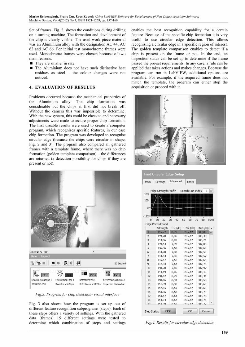
enables the best recognition capability for a certain feature. Because of the specific chip formation it is very useful to use circular edge detection. This allows recognising a circular edge in a specific region of interest. The golden template comparison enables to detect if a chip is present on the frame or not. In the end, an inspection status can be set up to determine if the frame passed the pre-set requirements. In any case, a rule can be applied that takes actions and makes changes. Because the program can run in LabVIEW, additional options are available. For example, if the acquired frame does not match the template, the program can either stop the acquisition or proceed with it.
Fig.4. Results for circular edge detection
Marko Reibenschuh, Franc Cus, Uros Zuperl: Using LabVIEW Software for Development of New Data Acquisition Software; Machine Design, Vol.4(2012) No.3, ISSN 1821-1259; pp. 157-160
160
Other programs similar to the one on Fig. 3 are under development. Different settings and different filters are used. Combinations are tested and comparisons are made between them to determine which one detects more features with greater accuracy and faster speed. More filters and more settings mean longer computational times and use of other computer resources. Therefore the programs must be as simple, short as possible so that the full capacity of the high speed camera can be used. If the buffer of the camera or the computer is occupied, then the acquisition discontinues and the sequence of the frames is interrupted. For simpler applications it is also possible to take a frame with another camera and use it as a template. Although it must be mentioned that the base point for taking frames must always be the same so that all settings fit to the observed area, tool position and work piece position. If not, the program can detect other features and recognise them as the desired feature. Table in Fig. 4 higlights the results for individual circular edge. On behalf of these results, a limitation is established which prevents the detection of undesired edges or features. This part of programing is time consuming – it demands the overview of all gathered frames and the measurement of all edges. This is necessary to determine the right values for setting the detection limits. Many other boundary conditions can be set and limited, depending on the chip phisical apperance, Fig. 5.
Fig.5. Setting the detection limits 5. CONCLUSION Results provide and insight into the chip formation. Visible chips can help determine the correct cutting parameters and the current cutting conditions. Some suggestions for cutting parameters are in the form of tables and books but because of new advancements in the field of materials, tables for such materials are till now not made. These gathered data are promising in establishing a program for chip detection for different types of materials. A chance for chip classification is also
possible, which means that the program is able to detect and classify short, broken off chips from long and winding ones, which are hazardous to the cutting tool and work piece. Other programs are in development where the program for chip detection and classification is directly linked to a program for changing the cutting parameters. In doing so, the final program will be able to change cutting parameters during the machining and prevent possible hazardous cutting conditions. The cameras ability to detect colour deviations is also a useful feature. Data from the camera can also be used for measuring the tool wear or chip thickness, depending of the settings. The disadvantage is the speed of the camera. Once more programs run at the same time, the camera response slows down and it is not able to detect at the pre-set values. Because of that it is recommendable to use short programs, which do not fully occupy the cameras and computers processor. Solutions in this field are under development and considering the very fast advancements in this field, they will be soon available. REFERENCES [1] Kious, M., Ouahabi, A., Boudraa, M., Serra, R.,
Cheknane, A. (2010) Detection process approach of tool wear in high speed milling. Measurement, Vol. 43, Iss. 10, December 2010, pp. 1439-1446.
[2] Dixit P. M. (2008) Modeling of metal forming and machining processes: by finite element and soft computing methods, Springer, London.
[3] Zarei, O., Fesanghary, M., Farshi, B., Jalili, S. R., Razfar, M. R. (2009): Optimization of multi-pass face-milling via harmony search algorithm, J Mater Process Technol 209:2386–2392.
[4] Jantunen E., A summary of methods applied to tool condition monitoring in drilling, 2002. International Journal of Machine Tools & Manufacture, 997-1010.
[5] Teti R., Jemielniak K., O'Donnell G., Dornfeld D., Advanced monitoring of machining operations, 2010. CIRP Annals – Manufacturing Technology 59, 717-739.
[6] Xu C., Chen H., Liu Z., Cheng Z., Condition monitoring of milling tool wear based on fractal dimension of vibration signals, 2009, Strojniški vestnik – Journal of Mechanical Engineering 55 (2009), Vol. 1, pp. 15-25