24
Using LOW-VOLUME FARM SPRAYERS CIRCULAR 126 / JANUARY 1959 45lgricii/tura/ 6 xperimnent Station of tte ,e ALABAMA POLYTECHNIC INSTITUTE E. V. Smith, Director Auburn, Alabama
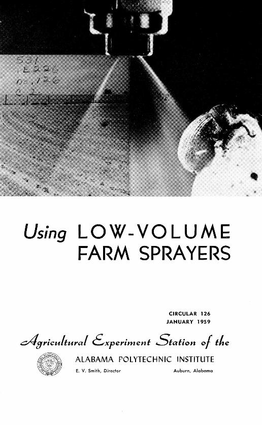
Using LOW-VOLUMEFARM SPRAYERS
CIRCULAR 126
/ JANUARY 1959
45lgricii/tura/ 6 xperimnent Station of tte
,e ALABAMA POLYTECHNIC INSTITUTEE. V. Smith, Director Auburn, Alabama

CONTENTS
Page
BASIC PARTS OF A SPRAYER ----------- -4
CA LIBR A TION ---------------------------------- --- 8
ADJUSTMENTS TO OBTAIN DESIRED APPLICATION RATE- 11
MIXING THE SPRAY SOLUTION -------- -13
SELECTION AND ADJUSTMENT OF EQUIPMENT FOR
DIFFERENT SPRAYING JOBS --------- -15
Pre-emergence Weed Control ----- -- -15Post-emergence Weed Control--- --- 16Insect C ontrol --------------- --- --------- -- --- -18D efoliation ---- -- - --- - --- - -- - --- - --- -- - --- - - 19Pasture W eed Control --------------- --- -20Wheel Fenders-20
High-Clearance Sprayers ------------------------------ 21M iscellaneous Spraying ------------------------------ 21
OPERATION AND CARE OF SPRAYERS ---------- _-----------.21
Beginning of Season Care ----------------------------21F ield O peration .------------------------------------- 22
D aily C are -- - - - - -- - - - - - - - - - - - - - - - - - - - - - - - - - - - - - - --2 2End of Season C are -------------------------------- 23
M ISCELLANEOUS ------ ------ ------------------------- 23
Tank Measuring or Cauge Stick ---------------------- 23Filling Tank with Spray Pump .----------------------. 23Caution About Using 2,4-D and 2,4,5-T----------------24
FIRST PRINTING 5M, JANUARY 1959

Using Low-VolumeFarm Sprayers
T. E. CORLEY, Associate Agricultural Engineer*
SINCE WORLD WAR II there has been increasing interest infarm use of liquid chemicals. This interest has centered arounddevelopment of chemical weed killers, liquid insecticides, liquidfertilizers, and liquid defoliants and desiccants.
Since high gallonage application of the chemicals in diluteform was sometimes ineffective and impractical, low-volumesprayers were needed. Engineers working with entomologistsdeveloped low gallonage, low-pressure sprayers that give effec-tive control of insects with applications as low as 1 gallon ofspray per acre. In this publication, a sprayer that delivers 1 to30 gallons of spray per acre at a pressure of 10 to 100 poundsper square inch (p.s.i.) is considered a low-volume sprayer.
New chemicals and sprayers have been developed at a muchfaster rate than have their use on farms. Several factors havecontributed to the rather slow acceptance of sprayers in Alabama.These include difficulties in mixing spray solutions, in determin-ing the volume of spray applied, and in using, adjusting, andcaring for the equipment. The purpose of this publication is toexplain proper sprayer use, how to calibrate the sprayer, how tomix chemicals, and special uses of spray equipment. The infor-mation presented is based mainly upon 10 years experience withsprayers in cotton mechanization research by the AgriculturalExperiment Station of the Alabama Polytechnic Institute. Inthese studies, sprayers were used for chemical weed control,insect control, and defoliation.
* Cooperative Agricultural Experiment Station of the Alabama PolytechnicInstitute and Agricultural Engineering Research Division, ARS, USDA.

To ozTo nozzles
_ Pump
SuctionHose
FIGURE 1. Basic parts of a sprayer are shown in this schematic diagram.
Basically, a sprayer is simple in construction and operation.Figure 1 is a schematic diagram of a sprayer. A typical tractorsprayer requires a pump mounted on the tractor power take-off(PTO) with a suction line connecting the pump to a tank mountedon the tractor. As the tractor PTO is rotated, the pump sucksthe spray liquid from the tank and puts it under pressure. Theliquid leaves the pump under pressure and goes through a hoseto a by-pass regulator where the pressure of the liquid going tothe nozzle is regulated and excess liquid is returned to the tank.The spray is applied through various types of nozzles, dependingupon the job to be done.
BASIC PARTS of A SPRAYER
Pumps. Pumps for low-volume sprayers should deliver at least5 gallons per minute at pressures up to 100 pounds per squareinch when rotated at 550 revolutions per minute. There are manytypes of pumps and several makes and models of each type.Selection of a pump depends on the material to be used, cost,and pressure and volume of spray to be applied. This Station hasnot conducted comparative tests of pumps, but it has purchasedand used gear, roller, diaphragm, and piston pumps, and thefollowing observations were made:
[4]

Gear and( roller pumps have short life spans xxhlen used forpuminug suspenisions of xxettable powder or dlirty, gritty wvater.Hlowexver, these pumps1~ haxve giv en satisfactorv serv ice for :3 or 4sprax irng seasons wvhen usedl for pumping emulsions and solutions.Diaphragmu and p~iston pump~1 s xxill handle wettab~le p~owxder solu-tions in addition to emululsions and solutions. These pum~ps re-
Murea air chamber in the line to give a steadyx flow of liquidto the niozzles.
Strainers. All spray ers should he equipped with strainers orscreens to prexvent Clogging of the nozzles, Figure 2. A strainershould he located either on the end of the suction hose or in theline lhetxxeeu tausk and pump and each nuozzle should he equipped
FIGURE 2. Strainers are necessary to prevent clogging of nozzles. A cloggedstrainer (left )is contrasted with clean nozzle strainer at right.
xxithi a stinr. Line and suction straiuuei s should haxve 50 to 100mnesh screens and the nozzle should haxve screens of 50 to 200mesh, depending upon size of nozzle orifice. The screen meshmust he selected to let all foreign particles [pass that xxill notclog the nozzle.
Hose. [ron the standpoint of p~resstire, garden hose is satis-factory for a loxvxolume spray er. Garden hose is also satisfactorxfor muost spra\ solutions lbut Ncophreiie hose should he used forhandling spray solutions Containing oil.
[51
Pressure regulator and gauge. The low-volume sprayer usesa positive displacement type pump. Since it pumps more thanthe nozzle is applying, a by-pass pressure regulator must be usedto return the excess liquid to the tank and to obtain the desirednozzle pressure. When the nozzles are not spraying, all liquidfrom the pump is returned through the by-pass. The excess li-quid returned through the by-pass serves to keep the spray solu-tion in the tank agitated. The nozzle pressure is easily andquickly changed by a simple screw adjustment of the pressureregulator. A gauge should be mounted near the regulator andin easy vision of the tractor driver. The gauge should have apressure range of 0 to 100 p.s.i.
Nozzles. According to the type of spray patterns produced,nozzles are classified as flat or fan, hollow cone, and solid cone.Each type is further classified according to capacity, and fan typenozzles are also classified according to angle of the spray pattern.These classifications apply to the nozzle tip because this part ofthe nozzle determines the type and volume of spray. The tipsare interchangeable and are easily removed and replaced. Mostfan type tips are marked to indicate the angle of spray patternand the capacity in gallons per minute at 40 p.s.i. Cone type tipsare usually marked to indicate gallons per hour at 40 p.s.i. Manu-facturers don't use the same markings but they all have chartsshowing the capacity of each tip. Types of tips needed forspecific jobs are discussed on pages 15-20.
Tanks. Clean 55-gallon steel drums can be used for most spray-ing jobs. Although low in cost, these drums rust and corrodeand have to be replaced after 1 or 2 years use. Stainless steeland aluminum tanks are more costly than steel drums, but theyresist the corrosive action of most chemicals and result in lessnozzle clogging and give many years of service.
Booms. Booms may be up to 30 feet in length, depending uponsmoothness of the ground and acreage to be sprayed. Boomslonger than 10 or 12 feet need flexible end sections that permitraising for gate and highway clearance and to facilitate turningin close places. Provisions for raising the end sections from thetractor seat are desirable but not necessary. Boom height shouldbe adjustable. Good coverage is usually obtained with the noz-zles about 20 inches above the plants. For row crop spraying,outlets should be spaced on the boom to permit mounting one
[6]

nozzle ov er the row' aicd a nozzle wvith all extension (drop pipe)between the rowxs. For 40-inch rowxs, the nozzle outlets shouldIhe spaed~ 20 inches apart on the boom. This same spacin g isalso satisfactory for b~roadcast sp~ray ing. Galv anized pipe may be
ed for the boom and drop extension s.
Mounting frame. A frame is nlecessar\ for supporting the tankandl boom. It should lbe strong enough to hold the tank andhooinS rigidLl\ wxithout swxax ing. A full .55-gallon dIrtm weighsalbout 500) poundi~s andl it sholld L e munted so as not to affectstab ility of the tractor. The fram e should be simplle to mi)Inntand dLetach. [or row~ crop sprax ing, the frame should hav e amp11leclearanee wxithotit aiiy low braces. Figure :3 shows a rear-ntotiiitedtanik andl 1)0011 support used for pre- and( post-emergeilee weedcon trol, cotton insect con trol, and1( defol iationI and1( a oluiiek-hiitch
FIGURE 3 (tap). At left is a rear-mounted tank and boom support with tample clearance to permit use of rearcultivator during pre- and pest-emerg-ence operations. Tractor wheel wasremoved to show axle mounting ofsupport. A quick-hitch tank support L Iwith bracket for mounting a broadcast pnozzle is at right.
FIGURE 4 (right). This front-mounted'tank support is used for pre-emerg-ence chemical application with plant-ers mounted on rear.__________

tank support with mounting bracket for broadcast nozzle. Afront-mounted tank support used for pre-emergence weed controlwith rear mounted planters is shown in Figure 4. Frames maybe purchased or "homemade" like those shown.
Large tanks (100 to 200 gallons) should be mounted on trailers.Several interconnected 55-gallon steel drums can be mounted onone trailer.
CALIBRATION
It is important to know how much spray the sprayer is apply-ing. Proper amounts of chemicals that should be applied for bestresults have been determined and the sprayer should be adjustedand operated to apply these recommended rates. Too much spraymay cause injury and is a costly waste, and too little spray willnot do the job.
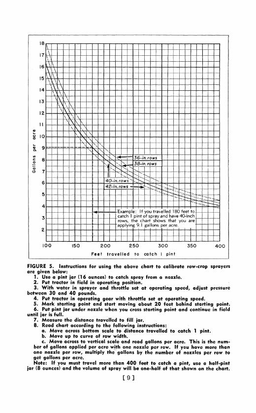
Calibrating or determining the amount of solution the sprayeris applying can be done by collecting and measuring the solutionfrom a nozzle while operating the sprayer over a measured dis-tance under conditions similar to those that will prevail whenactually spraying. The volume of spray applied per acre can thenbe calculated. To avoid complicated calculations, Figures 5 and6 can be used to determine rate of spray.
Figure 5. As shown in the instructions on Figure 5, its use isbased on catching spray from a nozzle until a pint jar is full. Iftwo people are available, one will drive the tractor and the otherwill walk and hold the jar under a nozzle. When the nozzle ismounted close to the ground as necessary for pre- and post-emergence weed control, the nozzle can be detached from themounting bracket so the jar may be conveniently held under it.To calibrate with one person or to eliminate the necessity ofdetaching a low-mounted nozzle, the following procedure canbe used:
With tractor stationary but running with throttle set at oper-ating speed, run sprayer and determine time in seconds requiredto catch a pint of spray from a nozzle. Then put tractor in fieldand determine how far it travels in that length of time. Thenread chart according to instructions. Example: If the tractortraveled 273 feet in the time required to collect a pint of spray,the chart shows you are applying 6 gallons per acre on 40-inchrows.
[8]
la
174
16
15H
14
13
12
Il
S10
u, 36-in. rows
- 38-in. row
I7 -
6 40-in, ro ws
42-in. rows
4, -
Example: If you taeld18 ett
Scatch 1 pint of sprayadhv 0icS -6rows, the chart h
Fee trvled t ach Ipn
ar e gve rowsw:
2. - -Pu t -t racorinfild n .pe Exaps i y t e 1 e3. ihwacan paerad t htt 1 pin t opratanghaveed0-inch resur
bewe10and0 20p20u00d50 404. ut ratorin peatFe earavelledtoteceatch oIpein ped
FIGUrk5strtipontfordusgthetaoveharot 2toalbaeirow-croipopryerare givent a ndbelow:e oucosstrigpon n cniu i il
1. MUsute a nt ta6nces)avllto atchlspayromanoze2. PuRacatraicfiedin opteat ing o it. ons
3. Withewaerosinotmspryradtottlestatoeraletctingspedpdjut.pesr
4. Putetrac to opratnv e aof rwwith.trtl e toeaigsed5. Mrkesarngpoinetcadsaartmngeaaos20peetacbe.histtinupint
6.rPutgapinsjaplundper ozze whencosslestaro.Itndyontineinofeldhau enti orisfll.e omlil heglosb h u br fnzlsprrwt
8.g ead alspraccrdigth.floigintutosa.o MoveI ro s mst tomve scae t t anc40 fe trvl to catch 1 pint.ea al-pnb.r Movun e)upndthoueof row wih. n-hl ftatsono tecat
c.Mvearostovrtclscl adredgalnsprace1Ti9i1henm

35
30
A 15
'- a I u . o s
5 refill tank and you are using a 30-
Gallons used to refill tank after spraying 300 feet
similar to that in field.
2. With water in sprayer and throttle set at operating speed, operate sprayerand adjust pressure to the desired setting (10 to 60 pounds).
sprayer over the 300-footdistance.
I_ I I/
-a. Move across bottom scale tox gallons used to refill tank.to5 r ! n ., !l refill tank and you are using a 30-
b. Move up to the line of your swath widthe chart shows youc. Move left to the verticarl scale applying 17 gallons per acre.
c. Move left to the vertical scale and read gallons per acre.
[10]

If you know how many gallons per acre that you want to apply,use chart as follows:
Move up the scale to gallons per acre desired, then across tothe curve of your row width, and down to get the distance totravel to catch a pint. Mark this distance off in the field to besprayed. Now with throttle set at operating speed, determinehow long it takes to travel this distance. Then with tractor sta-tionary but with throttle set at operating speed, change pressureand/or nozzle size until a pint is caught in the time required totravel the measured distance. If you change the throttle setting,you must again determine how long it takes to travel the requireddistance.
Example: If you want to apply 10 gallons per acre on 40-inchrows, the chart shows that you must travel 165 feet to catch apint. If it required 35 seconds to travel this distance, adjustpressure and/or nozzle size until a pint is collected in 35 seconds.Now your sprayer is adjusted to apply 10 gallons per acre.
Figure 5 was prepared primarily for row crop sprayers, but itcan be used for a broadcast boom sprayer. Example: A broadcastsprayer with nozzles spaced 20 inches on the boom would be thesame as a 40-inch row crop sprayer with 2 nozzles per row.
Figure 6. Figure 6 can be used for calibrating any type ofsprayer, but it was designed especially for a broadcast type.Since it is rather difficult to catch spray from a broadcast typenozzle, the amount of spray applied is determined by measuringthe volume sprayed from the tank. As described in the instruc-tions on Figure 6, this is done by starting with a full tank, spray-ing a measured distance, and measuring the amount needed torefill the tank. The tractor should be on level ground when thetank is filled and refilled, preferably in the exact location.
ADJUSTMENTS to OBTAIN DESIRED APPLICATION RATE
Figures 5 and 6 are used to determine how much liquid thesprayer is applying. If the desired amount of solution is notbeing applied, changes must be made and the sprayer must becalibrated again. The amount of liquid a sprayer applies peracre is governed by the speed of the sprayer, size of nozzle orifice,pressure, type of solution, and the nozzle spacing or number ofnozzles per row.
Pressure. The best way to make small changes in volume ofspray is to change the pressure. For most insect and weed spray-
[11]

ing jobs, the pressure may range between 20 and 100 pounds.The lower pressures (20 to 50 p.s.i.) are usually desirable becausewith lower pressure, a large orifice will give the same dischargeas a small orifice at high pressure. The larger orifice will give lesstrouble in clogging and produces larger droplets that reduce winddrift.
Example: A fan type nozzle with a rating of 0.1 gallon perminute requires a 100-mesh screen and will apply 10.4 gallonsper acre when operated at 80 pounds pressure at 2 miles perhour. A nozzle with a rating of 0.2 gallon per minute requiresa 50-mesh screen and will apply the same volume (10.4 gallonsper acre) when operated at 20 pounds pressure and at 2 milesper hour.
With the same orifice, the volume per acre can be changed bychanging the pressure. To double the volume of a nozzle, thepressure must be increased 4 times. The change in volume inrelation to pressure for a fan type nozzle with a rating of 0.2gallon per minute when operated at 3 miles per hour and with1 nozzle per row is as follows:
20 p.s.i. 6.9 gallons per acre30 " 8.4 p.P p
4 0 " 9 .9 . . .50 " 11.4 p
60 " 12.4 p p
80 13.8 pp. pp .p
100 " 15.8
The change in pressure also affects the spray angle. For bandspraying, this change may be compensated for by raising or low-ering the nozzle. For boom spraying, the overlap will takecare of slight pattern changes. With a broadcast type nozzle, theswath width may be affected 10 or 15 feet by pressure changes.
When calibrating a sprayer, start with a pressure of about30 pounds and increase or decrease to make minor changes involume.
Nozzle orifice. The best way to make a large volume changeis to vary the size of nozzle orifice or opening by changing noz-zle tips. The amount of spray a nozzle delivers is in direct pro-portion to the square of the diameter of the orifice opening. Inother words, if the diameter of the orifice is doubled the volumeis increased 4 times.
Most nozzle orifices are not designated or rated by diameterbut by capacities in gallons per minute or gallons per hour at
[12]

a certain pressure. In selecting a nozzle size, refer to tables thatgive volume per acre at different speeds.
Example: The capacity of 1 nozzle per 40-inch row operatingat a pressure of 40 pounds varies with nozzle size and speed asfollows:
Nozzle rating Speed (m.p.h.)
Gallons/min. Gallons/hr. 3 4 5 6Gallons per acre
0.05 3 2.5 1.8 1.5 1.20.1 6 5.0 3.7 3.0 2.50.2 12 10.0 7.4 6.0 5.00.3 18 15.0 11.1 9.0 7.50.4 24 20.0 14.8 12.0 10.0
If it is desired to apply 10 gallons per acre with 1 nozzle per40-inch row, select a 0.2 nozzle tip if traveling 3 m.p.h. but a 0.3tip if traveling 4 m.p.h. After selecting the nozzle tip, it may benecessary to make slight pressure changes to get exactly 10gallons per acre.
Speed of sprayer. The speed of the tractor or sprayer shouldbe the last variable to change. When applying pre- and post-emergence weed control chemicals, the speed should be gov-erned by the planting and cultivating speed. In pasture sprayingand cotton poisoning and defoliating, speed is governed by ter-rain, safety, and damage to crop. Volume is indirectly relatedto speed. When the speed is doubled, the volume is reduced byone half.
Nozzle spacing or nozzles per row. The amount of spray isdirectly related to the number of nozzles per row.
Type of liquid. When a chemical is diluted with water, thesprayer can be calibrated with plain water. If the chemical is anoil or is diluted with oil, the same oil must be used for calibration.
MIXING the SPRAY SOLUTION
After the sprayer has been calibrated to determine its rate ofspraying, the concentrate chemical must be mixed in correct pro-portion with water. The strength of most spray chemicals ismarked on the container and is usually expressed in per cent ofactive ingredients and/or pounds of technical material per gallon.Many chemicals are sold at different concentrations and it isimportant to read the container label before mixing and using.Example: Toxaphene may be purchased with 4, 6, or 8 pounds
[13]

of technical material per gallon. Most recommendations are ex-pressed in terms of pounds of technical material per acre.
It is relatively simple to mix the spray solution if the followingthree things are known: (1) amount of solution the sprayer isapplying per acre, (2) pounds of technical material per gallon ofconcentrate chemical to be used, and (3) pounds of technicalmaterial recommended per acre. Example: Assume that (1) yoursprayer is applying 5 gallons per acre, (2) you are using toxaphenecontaining 4 pounds of technical material per gallon, and (3) youwish to apply 2 pounds of technical toxaphene per acre. Eachgallon of the toxaphene contains enough technical material for
4 pounds per gallonacresacres = 2 acres Or 1/ gallon of this
2 are 2 pounds per acre -toxaphene contains enough technical material for 1 acre. There-fore, for each acre you should mix 1/ gallon of concentrate toxa-phene with 41/2 gallons of water. Or for each gallon you shouldmix 9 gallons of water. To mix a 55-gallon drum of spray(enough for 11 acres), fill drum about half full with water, putin 51/2 gallons of concentrate toxaphene (enough for 11 acres)and then fill drum with water. Always have water in the tankwhen adding concentrate chemicals. After pouring the waterand chemical in the tank, operate the pump for several minuteswith the nozzles turned off to thoroughly mix the spray solution.
All chemicals are not marked in terms of technical materialper gallon. However, the label or the recommendations will tellhow much of the concentrate chemical to apply per acre.
The strength of wettable powders is expressed in percentageof active ingredients, and the recommendations are usually interms of pounds of powder per acre. Make sure that the powdersare thoroughly mixed with water before pouring into the tank.
CAUTION. Before mixing any chemical, read and understandthe precautions and directions for safe handling. This informa-tion is on the container label. The mixing process involves hand-ling highly concentrated chemicals and even non-toxic chemicalsin concentrate form can cause severe burning, blistering, andother harmful effects. Avoid as much as possible contact of thechemical with skin and clothing. If the chemical gets on theskin, wash thoroughly with soap and water immediately. If itgets on clothing, remove clothing at once. Always have soapand water readily available. Make sure that measuring and mix-ing containers are thoroughly washed before using for otherpurposes.
[14]

SELECTION and ADJUSTMENT of EQUIPMENT forDIFFERENT SPRAYING JOBS
The h~asic elements of a spraver (pump, strainers, hoses, andtauk) may he used for many jobs. Nozzle tvpes, sizes, arrange-ients, andl methods of mounting varv with the joh.
Pre-emergence Weed Control
Pre-emergence chemicals are applied after planting and beforethe crop and weeds emerge or come up. Cotton, peanuts, andlcorn are the main crops in Alahama that lend themselv es to pre-emergence treatment. Although chemicals can be applied broad-cast oxver the entire field, it is more economical to treat onlx therow (hand application) anld use sweeps to control weeds betweenrowxs.
For hand application, the chemical should he applied in con-nection with the planting operation. Application of the chemicalafter crop is planted means an extra operation, makes it difficultto center hand over the planted row, and introduces a chance ofrain preventilg treatment hefore the crop emerges.
To apply pre-emengence chemical at planting, mount thespraxver on the tractor with a nozzle over each row. The fan typenozzle with an ex en, flat spray pattern was designed for hand
Ps .. _~
-S 6 ~'^-a- ::~ t a~-i T -~" L
FIGURE 7. Distribution pattern of an even, flat spray nozzle at right is comparedwith a regular, flat nozzle with a tapered edge pattern at left.
[15 1
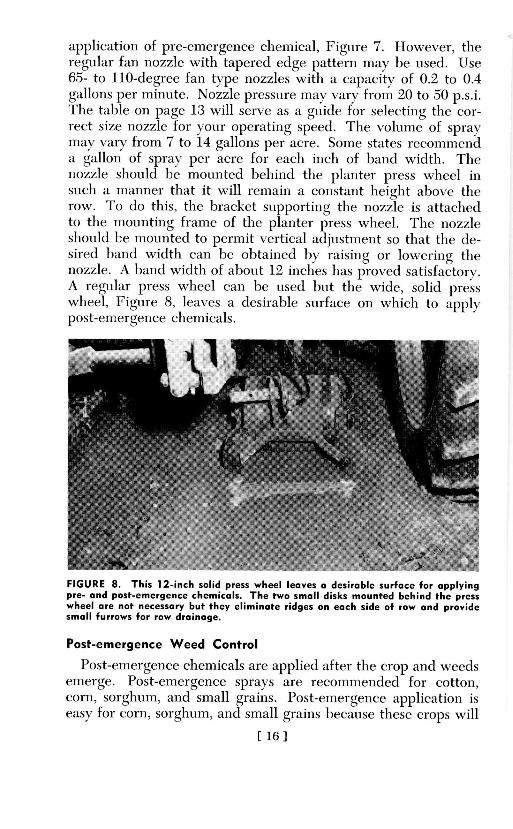
application of pre-emergence chemical, Figure 7. However, theregular fan nozzle with tapered edge pattern may be used. Use6.5- to 110-degree fan ty pe nozzles with a capacity of 0.2 to 0.4gallons per minute . Nozzle pressure may xvary from 20 to .50 p.s.i.The table on page 13 will serve as a guide for selecting the cor-rect size nozzle for your operating speed. The volume of spraymay v ary from 7 to 14 gallons per acre. Some states recommendla gallon of spray per acre for each inch of band wx idth. Theiozzle should be mounted b~ehind the planmter press wheel insuch a manner that it xill remain a constant height abov e therow. To (10 this, the bracket supporting the nozzle is attachedlto the mounting frame of the planter press wheel. The nozzleshould b;e mounted to permmit vertical adjllstlent so that the de-sired hand width can be ohtained by raising or lowering tgthenozzle. A band width of about 12 inches has prove satisfactorx.A regular press xxheel can he used but the xxide, solid presswx heel, Figuire 8, leav es a desirable surface oi xhich to applypost-emergence chemicals.
FIGURE 8. This 12-inch solid press wheel leaves a desirable surface far applyingpre- and past-emergence chemicals. The two small disks mounted behind the presswheel are not necessary but they eliminate ridges on each side of row and providesmall furrows for row drainage.
Post-emergence Weed Control
Poost-emergence chemicals are applied after the crop and weedsemerge. Post-emergen ce sprays are recommenided for cotton,corn, sorghum, and small grains. Post-emergence application iseasy for corn, sorghum, and small grains because these crops will
[16]

tolerate light dloses of the weed-killing cheicals. Although cornand( sorghum wXill tolerate th~e weed-killing chemicals, the ntoz-zles should he set to direct spray toward base of the stalk toprev ent chemical from hitting the corn or sorghum leaves. Insmall corn, the nozzles can he attached to the cultix ator. Forlarge corn, an oxverhead hoom with) drops ini each middle isneedled. Post-emergence weed control in cotton is more dlifflecultbecause the wxeed- killing chemicals cannot hit the yo0u1ng Cottonleax es wXithout damaging or killing the cotton. Ilowex er, thechemiicals max strike the shank of the v oting cotton stalk beforethe true hark forms without damaging it. This makes it possib~leto spray small grass and wxeedis ini the drill wxithiout dlamaging the(jottonl. C;ottont plants should be at least 21. . to :3 inches tall attime of first application. The chemical should be applied wxithouitdlistmirbing the soil in the (Irill. At the same time, the midd~les caunbe cultivated wXith sweelps. The chemical can be app~lied whenthe groundl is too wXet for swe ep cuiltiv ation but wvill sulpport thetractor.
Figure 9 shoxvs shields used to keep the swxeeps fromt throwxinigdlirt in to the rowv crill . Nozzles m oulntedl on the shieilds are di-
FIGURE 9. Shown are parallel action shields with nozzles (arrows) mounted forapplying post-emergence chemicals. These shields prevent sweeps throwing dirton the row when cultivating and applying post-emergence chemicals.
[I17]
rected to spray weeds in the drill. The flat plate on the boottomof the shield and the parallel linkage cause the shields to float onthe ground surface, thereby keeping the nozzles at the saeheight. The nozzles should lbe mountl on each side of the rowabout 1 inch above the grolnd surface and directed so that thesprax hits only the bottom inch of the cotton stalk. The nozzlesmay be directed to the rear at an angle of ahouit 30 to 40 degreeswith the rox or pointed straight across the row. In either case,the nozzles should be set to cover an 8- to 10-inch band on therow. If the nozzles are poinrted straight into the row, make surethat thex are offset (not set opposite each other) so that the sprav swill iot meet an(d "bounce" up1 and onto the cotton.
For post-emergence spraying, use 65- to 95-degree fan tx penozzles xith a capacitx of 0.05 to 0.1 gallon per minute. ()perat-ing pressure ma xvarx between 1.5 and 40 p.s.i.
Insect Control
Spraxers cain be used effectively to apply ilsecticides on mostcrops. Nozzle arrangement varies with the cjop and insect.
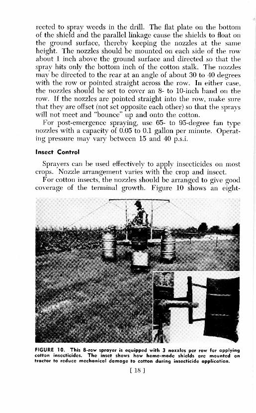
For cotton insects, the nozzles should be arranged to gixve goodcoverage of the terminal growth. Fiiure 10 shows anl eight-
A--- ~
FIGURE 10. This 8-row sprayer is equipped with 3 nozzles per raw for applyingcotton insecticides. The inset shows how home-mode shields are mounted ontractor to reduce mechanical damage to cotton during insecticide application.
[18I8
row sprayer for applying insecticides to cotton. This sprayer isequipped with 3 nozzles per row (1 centered over the row and1 on each side). This nozzle arrangement has given good controlin test work in Alabama. For small cotton, 1 or 2 nozzles per rowwill give good coverage.
Cone nozzles with a capacity of 4 to 6 gallons per hour or fannozzles of equal capacity (0.067 to 0.1 gallon per minute) are rec-ommended for applying most cotton insecticides. Nozzles withsmaller orifices will give adequate coverage but cause more trou-ble in clogging. Nozzles with larger orifices can also be used andmay be needed during windy weather and for high rates of ap-plication. The table on page 13 may be used as a guide forselecting nozzle size. Good coverage can be obtained with 5 to10 gallons of spray solution per acre.
For the corn earworm (on sweet corn), direct the spray intothe ear zone. Because of non-uniform ear height, 2 nozzles oneach side of the row should be used.
For the corn borer, use 1 nozzle above the row and 1 on eachside, directed to get the spray into the whorls.
Defoliation
Cotton is the main crop that is chemically defoliated in Ala-bama. Defoliants can be applied with the same equipment usedfor applying insecticides. Larger volumes of spray are neededfor defoliation than for insect control because each leaf must re-ceive an application of the chemical. Defoliants should be ap-plied in 15 to 25 gallons of water per acre. A coarse spray withlarge droplets is desirable. The larger nozzles recommended forinsect control can be used for applying defoliants. An overheadboom with drop extensions in each middle and 3 to 6 nozzles perrow will give good coverage in cotton under 5 feet in height.For larger cotton, a second application is usually needed.
The broadcast type nozzle, Figure 11, has given excellent de-foliation in tall irrigated cotton for 2 years at Auburn. Goodcoverage was obtained on all rows of an 8-row swath, but withwider swaths outside rows did not always get ample coverage.
Flooding type nozzles mounted overhead have given excellentresults in defoliating rank cotton in other states.
Sometimes it may be desirable to defoliate the lower part ofcotton plants without disturbing the top. This can be done byusing an overhead boom with a drop extension in each middle.Mount nozzles only on the drop extensions and direct them to
[19]

BROADCAST SPRAY NOZZLE
FIGURE 11. Shown above is one type of broadcast nozzle. This nozzle coversswaths up to 60 feet.
coy er tbe lower portion of the plant. A shield (6 to 8 incheswide) miounted oni the drop) extension will keep leax es fromlhriishiiig aicross the nozzle orifice.
Pasture Weed Control
The greatest use of lowx-v ohlme sprav ers in Alabama has beenfor sprax ing wxeedls in pa~stuires. Broadcast ty pe spray ers are nsedfor p~astuire spray ing and arc of two ty pes: (1) boom 'tx pc sprax erswith f an nozzles spaced 18 to 2() inches on the boom, and (2)biroadcast nozzle ty pe spray ers with a cluster of nozzles arrangedto cox er a wide swath. The b~roadlcast tx pe nozzle has becomexvcry popuilar for pastuire weed control. Spray ing xxith a b~roadcastnozzle as compared to spray ing wxith at b)oom type sprayecr has thefollowxing adx amtages: (1) lowxer equnipnment cost, (2) fewxer noz)!
zlcs to maintain and to causecloggn~. (>) easier to operate, and(4) pemt spaing wider swxaths. Disadv antages of spra inigwith a hroadcast nozzle are: (1) wxin d unatcriallx affects the noz-zle pattern, (2) difficuilt to maintain uniiform distan ce 1 etwe ccnwxide swxaths, and (3) greater danger of spray ing nearlby cro ps.
With either ty pe spray er, good cov erage may lbe obtainecd wxithI ( to 25 gallon s per acre. For large acreage, trailer ty pe spray ersequlipped with large tanks arc desirable.
Wheel Fenders
M echoan ical damage to crop)s caused byx ground applicators ofinsecticidles max he quite serious, especciallx during late seasoniin tall crops. Whleel fenders such as those shown in Figure 10( aidgreatly in reducing this damage.. These are . shop-mnade" fenders
[ 20 1
constructed from a 30-gallon insecticide drum and mounted tothe sprayer frame. They can be mounted independent of thesprayer frame by clamping to the tractor axle. They are mountedin a fixed position and a piece of 10-inch belting is fastened tothe bottom of the drum. This belting will push the low limbsout of the way of the tractor wheel but will give or flex when thewheel drops in a ditch or crosses a terrace channel. Wheel fend-ers such as these may be constructed and adapted to any maketractor. Similar wheel fenders are available commercially.
High-Clearance Sprayers
Self-propelled, high-clearance sprayers are relatively costly,but they are desirable for use on large farms and by custom op-erators. The use of self-propelled, high-clearance sprayers re-duces mechanical damage to growing crops and eliminates needof a farm tractor for spraying.
High-clearance sprayers are especially adapted for applicationof chemicals in tall crops, such as corn and irrigated cotton. Theymay also be used to apply liquid fertilizer, chemicals for weedcontrol in pasture or row crops, cotton defoliants, and for otherspraying jobs.
Miscellaneous Spraying
The low-volume farm sprayer can be used for spraying live-stock, buildings, manure piles, orchards, ditchbanks, fence rows,and shrubs, for washing and cleaning farm equipment, for fight-ing fires, and numerous other jobs.
A hand gun and a 25-foot hose are the only extra equipmentneeded to adapt a row crop or pasture sprayer for the abovemiscellaneous spray jobs.
OPERATION and CARE of SPRAYERS
Beginning of Season Care
1. The sprayer mounting frame should be fastened securelyand braced properly to the tractor.
2. All pipe and hose connections should be leakproof.
3. Make sure that pump can be turned by hand before mount-ing it on the tractor PTO. (Note: If pump cannot be turnedby hand, it should be disassembled according to instructionsfurnished with pump.)
[21]
4. Do not pound or hammer the pump to get it on the tractorPTO. If the PTO shaft and the pump coupling are clean andfree of rust, the pump should go on easily.
5. Secure pump to PTO by means of set screws and anchorpump to sprayer or tractor with chain or chains.
6. Inspect tank and make sure it is clean before mounting.
7. Flush boom with water before attaching the nozzles.
8. Inspect nozzle screens and tips for cleanliness and to makecertain all tips are of the same size.
9. Run sprayer to check for leaks and to observe nozzle pat-terns. Irregular shaped nozzle patterns may be detected by ob-servation and must be corrected. They are usually caused bytrash or dirt in and around the nozzle orifice or by a cloggednozzle screen. Do not probe the nozzle orifice with a knife bladeor other metal objects. Use a tooth brush or soft wood to cleanthe orifice.
10. Calibrate sprayer and mark throttle setting and record gearposition.
11. Calculate the ratio of concentrate chemical and water andrecord mixing instructions on tank or other convenient place.
Field Operation
1. It is of utmost importance to always use a clean spraysolution.
2. Operate tractor in the same gear and at the same throttlesetting as used for calibration.
3. Observe nozzle patterns continuously to detect clogged noz-zles and to tell when tank is empty.
4. Do not operate pump when tank is empty. Gear and rollerpumps can be seriously damaged by operating dry only a fewminutes.
Daily Care
1. At the end of a day's spraying, flush system with cleanwater.
2. Check suction and line strainers and nozzle tips and screensand clean if necessary. Clean tips and screens by soaking ingasoline and brushing with a small brush or use compressed air.
[22]

End of Season Care1. Flush system thoroughly with clean water and then run a
few gallons of fuel oil through sprayer to help prevent rust.2. Remove and clean nozzles.3. Remove and drain pump. Before storing, gear and piston
pumps should be filled with oil and roller and diaphragm pumpsshould be flushed with a rust inhibitor. All openings in thepumps should be plugged.
4. Apply a coating of oil to the inside surface of steel tanks.5. Store sprayer under a shed.
MISCELLANEOUSTank Measuring or Gauge Stick
It's a simple matter to mark a stick to use for measuring theamount of liquid in your sprayer tank. With the tank level, add5 gallons of liquid, insert stick in tank, and then mark or notchstick. Continue to add 5 gallons at a time and mark stick untiltank is full. Always make sure the tank is level when using thegauge stick.
The following figures have been obtained for measuring theamount of liquid in a 55-gallon steel drum in a horizontal po-sition:
Inches per 5 gallons Gallons per inch
Gallons Inches Inches Gallons Inches Gallons5 31/8 1 11/4 11 281/4
10 51/ 2 3 12 311/215 67/8 3 43/ 13 3420 81/ 4 7 14 3725 10 5 93/ 15 403/430 111/2 6 12/2 16 433/35 131/8 7 151/ 17 46/40 143/4 8 181/2 18 491/245 16% 9 211/ 19 521/4.50 181/8 10 25 20 541/455 20%
For a 55-gallon drum in a vertical position, each inch repre-sents about 1.7 gallons.
Filling Tank with Spray Pump
The pump on the sprayer may be used to fill the tank asfollows:
1. Remove suction line from tank and place it in the watersource (creek, pond, or supply tank). Be sure to have suctionstrainer on suction line.
[23]

2. Unscrew the pressure regulator to drop pressure to 0-20 p.s.i.3. Keep by-pass hose in tank to be filled.4. Engage pump and water will flow through the by-pass hose
into tank.5. Re-set pressure regulator after tank is filled.
Caution About Using 2,4-D and 2,4,5-T
A sprayer that has been used to apply 2,4-D or 2,4,5-T shouldnot be used for applying insecticides or fungicides to broadleafplants such as cotton, soybeans, and vegetables. Even if thesprayer has been thoroughly flushed with clean water, there islikely to be enough 2,4-D or 2,4,5-T left to damage sensitivecrops. However, the sprayer may be used to spray livestock. Donot spray 2,4-D or 2,4,5-T near sensitive plants, especially whenthe wind is blowing toward the plants. To reduce drift, use alow pressure and a large nozzle orifice to produce large droplets.
In order that the text content be readily understood, it is neces-sary at times to illustrate or use trade names of products orequipment rather than involved descriptions or complicatedchemical identifications. In some cases it is unavoidable thatsimilar products on the market under other trade names are notcited. No endorsement of named products is intended, nor iscriticism implied of similar products that are not mentioned.


