etc2016 – 36 th European Telemetry and Test Conference 166 DOI 10.5162/etc2016/5.3 Using LTE-networks for UAS-communication Felix Maiwald and Axel Schulte Institute of Flight Systems Universität der Bundeswehr München (UBM) 85577 Neubiberg, GERMANY {felix.maiwald, axel.schulte}@unibw.de Abstract This article discusses the usage of Long-Term Evolution (LTE) as IP-datalink for one or multiple micro unmanned aircraft systems (UAS). LTE offers robust coding schemes as well as very high sensitivity of receivers. In environments of highly limited transmit power, LTE therefore promises much better coverage in comparison to commercially applied UAS-datalinks like Wi-Fi or Lightbridge (DJI). Within this article, two commercial LTE-networks are evaluated and necessary IT-infrastructure for communication with UAS is specified. We also describe the integration of our multicopter-UAS into a commercial LTE-network. Thereby we developed a Linux-based tablet solution for guidance of our UAS via LTE. This includes the transmission of a live-video stream from our UAS to our tablet via LTE. In the contribution, we present the results of flight experiments we conducted at our testing site. The experiments show that guidance of small drones (including transmission of telemetry and sensor data) via public LTE infrastructure is feasible. Quantitative performance measurements will be presented in the paper. Future work comprises the setup of an own LTE-network and the guidance of multiple UAS via public LTE as well as via an own LTE-network. Key words: UAS, LTE infrastructure, Live Video and Command Link 1. Introduction In the recent years micro unmanned aircraft systems (UAS), commonly known as drones, found the way into public domain. These drones will be applied in civil, military and research applications, as well as leisure activities, policing, surveillance and security work (e.g. inspection of power lines). For this type of applications, there is the requirement to transmit large sensor data to the UAS operator. Analog data transmission is not capable to satisfy these requirements. The fixed video bandwidth and noise artifacts during flight phases with low signal strength prevent a high quality transmission of large sensor data frames. Consequently noncommercial drones often use IP-based Datalinks like Wi-Fi (e.g. Parrot Bebob Drone) or proprietary Datalinks (e.g. DJI Lightbridge at 2.4 GHz ISM for video and 5 GHz for commands [1]) as communication link between pilot and the UAS. Using a Wi-Fi network seems to be interesting because of its low system price, low weight, and vendor independent availability. However, the legally permitted transmission power of Wi-Fi is limited by the federal network agencies (e.g. 100 mW EIRP for IEEE802.11n in Germany). The coverage of such data links is limited to direct environment only. Directional antennas with tracking functionality promise to increase the link coverage for single UAS but will violate the restrictions in transmission power due to antenna gain. Such antenna configuration also does not allow the simultaneous communication with multiple UASs. The Institute of Flight Systems at the UBM investigates Manned-Unmanned Teaming Missions (MUM-T) where drones are guided from aboard a manned helicopter in a simulation setup. In another study, we also examine the support of infantry by drones in an urban scenario. The UAS carries at least one electro-optical sensor, which continuously delivers reconnaissance pictures. For both studies, real-time reconnaissance data (live video link) should be transmitted to the mobile ground station. The transmitted data also includes commands like further waypoints/routes and telemetry data such as current UAS-position and the status data. This information are necessary for the UAS- operator. In this scenario, data transport from and to UAS should be realized via IP. Hence, the Institute of Flight Systems investigates on innovative IP-
Transcript
etc2016 – 36th European Telemetry and Test Conference 166
DOI 10.5162/etc2016/5.3
Using LTE-networks for UAS-communication Felix Maiwald and Axel Schulte
Institute of Flight Systems Universität der Bundeswehr München (UBM)
Abstract This article discusses the usage of Long-Term Evolution (LTE) as IP-datalink for one or multiple micro unmanned aircraft systems (UAS). LTE offers robust coding schemes as well as very high sensitivity of receivers. In environments of highly limited transmit power, LTE therefore promises much better coverage in comparison to commercially applied UAS-datalinks like Wi-Fi or Lightbridge (DJI). Within this article, two commercial LTE-networks are evaluated and necessary IT-infrastructure for communication with UAS is specified. We also describe the integration of our multicopter-UAS into a commercial LTE-network. Thereby we developed a Linux-based tablet solution for guidance of our UAS via LTE. This includes the transmission of a live-video stream from our UAS to our tablet via LTE. In the contribution, we present the results of flight experiments we conducted at our testing site. The experiments show that guidance of small drones (including transmission of telemetry and sensor data) via public LTE infrastructure is feasible. Quantitative performance measurements will be presented in the paper. Future work comprises the setup of an own LTE-network and the guidance of multiple UAS via public LTE as well as via an own LTE-network.
Key words: UAS, LTE infrastructure, Live Video and Command Link
1. Introduction In the recent years micro unmanned aircraft systems (UAS), commonly known as drones, found the way into public domain. These drones will be applied in civil, military and research applications, as well as leisure activities, policing, surveillance and security work (e.g. inspection of power lines). For this type of applications, there is the requirement to transmit large sensor data to the UAS operator. Analog data transmission is not capable to satisfy these requirements. The fixed video bandwidth and noise artifacts during flight phases with low signal strength prevent a high quality transmission of large sensor data frames.
Consequently noncommercial drones often use IP-based Datalinks like Wi-Fi (e.g. Parrot Bebob Drone) or proprietary Datalinks (e.g. DJI Lightbridge at 2.4 GHz ISM for video and 5 GHz for commands [1]) as communication link between pilot and the UAS. Using a Wi-Fi network seems to be interesting because of its low system price, low weight, and vendor independent availability. However, the legally permitted transmission power of Wi-Fi is limited by the federal network agencies (e.g. 100 mW EIRP for IEEE802.11n in Germany). The
coverage of such data links is limited to direct environment only. Directional antennas with tracking functionality promise to increase the link coverage for single UAS but will violate the restrictions in transmission power due to antenna gain. Such antenna configuration also does not allow the simultaneous communication with multiple UASs.
The Institute of Flight Systems at the UBM investigates Manned-Unmanned Teaming Missions (MUM-T) where drones are guided from aboard a manned helicopter in a simulation setup. In another study, we also examine the support of infantry by drones in an urban scenario. The UAS carries at least one electro-optical sensor, which continuously delivers reconnaissance pictures. For both studies, real-time reconnaissance data (live video link) should be transmitted to the mobile ground station. The transmitted data also includes commands like further waypoints/routes and telemetry data such as current UAS-position and the status data. This information are necessary for the UAS-operator.
In this scenario, data transport from and to UAS should be realized via IP. Hence, the Institute of Flight Systems investigates on innovative IP-
etc2016 – 36th European Telemetry and Test Conference 167
DOI 10.5162/etc2016/5.3
based datalinks for communicating with UAS. The Long-Term Evolution (LTE) might be a pioneering technology for such datalinks as it offers robust coding schemes as well as very high sensitivity of receivers. In this article, we present a concept and first results when using a public LTE-network to transmit sensor data as well as commands between UAS and to the ground-based control station.
This paper is organized as follows. Section 2 describes the data-link for UAS, which has been formerly used at the UBM while Section 3 clarifies the lessons learned and requirements for a preferable UAS data-link. Section 4 assesses candidates for the data-link. Section 5 introduces a concept and basic evaluation of a data-link for UAS, which is based on commercial LTE-networks. Section 6 contains the evaluation of UAS-guidance in flight test via commercial LTE. Section 7 presents activities for set-up own LTE-network infrastructure at the Institute of Flight Systems.
2. Former work at the UBM Before the UBM was investigating LTE technology, we used IEEE 802.11n-based data links for communicating between our fixed wing RC electric glider and the ground station (see Figure 1). The experimental set-up is described in [2]. Main results are recapped in the following. The glider is hand launched and equipped with a 1200 Watts electric propulsion system. The hull has been modified to accommodate an autopilot and a payload module containing two embedded computer boards. As a bridge data-link to the ground station we use a compact PCI Express 5GHz 802.11n module with +20 dBm transmit power and +5 dBm antenna.
Figure 1: RC-Glider of UBM The payload configuration consists of a video camera generating a 1080p stream @30 Hz MJPEG requiring a bandwidth of approximately 8 Mbit/s.
The ground station integrates 4 computers with two touchscreens and features a pan/tilt platform with two integrated 5 GHz directional antennas (16 dB gain) and 802.11n routers. For
testing purpose only we set output power to +20 dBm. In our flight tests the radio link distance between ground station and glider ranged up to 550m.
Figure 2: Approx. Maximum Mission Distance 5 GHz IEEE802.11n @ +20 dBm TX-Power (taken from [2]) The effective connection rate of the radio link depends on the distance between the UAS and the ground station, as well as the antenna orientation and the shadowing by the UAV itself (cf. Figure 2).
Thus attitude changes during flight result in a fluctuating connection rate. Figure 3 shows the observed dependence qualitatively. Up to a distance of approximately 180m data streams could be delivered to ground station without losses. A variable delay of video frames of about 50…80ms is observed. This jitter of about 30ms is caused by requesting lost packets by the TCP protocol, which is acceptable and not disturbing. In distances between 180m and 550m, video streams responded to the worsening data connection with a frame drop, which led to a lower frame rate on the operator screen. At greater distances than approximately 550m, the effective connection speed dropped to less than 2Mbit/s. Here it was not possible to transfer the mission-critical high-resolution reconnaissance images to the ground control station.
Figure 3: 802.11n TCP throughput (taken from [2])
etc2016 – 36th European Telemetry and Test Conference 168
DOI 10.5162/etc2016/5.3
The results allow the conclusion that – despite using directional antennas with 16 dB gain – the absolute maximum distance for a successful mission fulfilment based on IEE802.11n data-link is far below 550m.
3. Requirements for Data transmission The previous trials revealed that TCP throughput using an IEEE802.11n data-link is convincing for slow moving platforms in close vicinity.
Our future activities consider data-links for moving UAS in wide area applications. We also extend the scenario with multiple UAS, which have to be connected via a data-link simultaneously.
The results of our findings are the base for specification of requirements for an UAS data-link. These requirements comprise the following topics:
a) High Robustness and Reliability
The air vehicles cruise with different speeds, up to 30m/s at maximum. This will result in rapidly changing receiving conditions (cf. multipath etc.). The data link should be robust being able to cope with those conditions.
b) High Data rate
The data-link is used for transmitting real-time reconnaissance data to the ground station. As a result the data-link should be broadband. Data should be transmitted with a minimum of 8 Mbit/s.
c) Low latency
The data-link may also be used for guiding the UAS via first person view (FPV) which requires low latency data transmission. A maximum of 80ms is acceptable for packet delay.
d) High Coverage
High coverage is mandatory not to lose the data connection – preferable sized 1 km radius from the start point at minimum. Data rate must not break down significantly in the edge of the cell.
e) Short time for resynchronization in case of link lost
If link lost occurs in spite of high coverage, the connection should be established again very quickly.
f) Legality
It has to be ensured that legal restrictions (i.e. allowed transmit power, license for frequency usage) must not be violated.
g) Capable of Multi-UAS Scenario
The UBM also investigates in scenarios, where several UAS will be located dynamically in an urban mission. The datalink should be able for simultaneously communication with several airborne entities, which are located at different positions.
4. Technical overview of candidates for a data-link
Consulting the above noted requirements, we consider the following three options as possible candidates for a data-link:
Wi-Fi
Commercial LTE provider
Own LTE network
Technical assessment on Wi-Fi At first we examine IEEE802.11n on fulfillment of the before noted and extended requirements.
IEEE802.11n is a wireless networking standard that uses multiple antennas to increase data rates. Theoretically, 802.11n networks can achieve up to 150 Mbit/s if there are no Bluetooth, microwave or other Wi-Fi emissions in the vicinity. It can be used in the 2.4 GHz or 5 GHz frequency bands and achieves short delays.
Due to German legal regulations of IEEE802.11n only very low transmission power is allowed. However, in a wide area scenario the likelihood of Wi-Fi packet loss will rise. TCP misinterprets packet loss as congestion – a dropdown in performance is likely to occur. Asadpour et al. [3] postulate that the automatic rate adaptation functionality of standard 802.11n chipsets cannot cope with the high mobility of UAS. Since Wi-Fi is released for generally use, interferences from other devices in the vicinity are to be expected. Hence, the stable coverage of 802.11n is quite limited – operations without directional antennas are not feasible. In case of using directional antennas the equivalent output power (EIRP) will go beyond existing legal regulations. The necessity of directional antennas makes scenarios with multi-UAS not feasible. The time for resynchronization (in case of link lost) cannot be measured exactly – but we assume a range of seconds from our observations.
Technical overview and assessment on LTE With the introduction of LTE mobile technology it is possible to provide a mobile broadband access that has the potential to become a viable alternative to fixed broadband connection in terms of bandwidth and latency. The aim and design of the LTE system architecture (SAE)
etc2016 – 36th European Telemetry and Test Conference 169
DOI 10.5162/etc2016/5.3
and concepts are to efficiently support mass-market usage of any IP-based service.
LTE Rel. 8 fulfills the most notable of our requirements: To overcome the effect of frequency-selective fading due to multipath (known in other technologies like UMTS) LTE uses Orthogonal Frequency Division Multiplexing (OFDM) for the downlink. OFDM uses a large number of narrow sub-carriers for multi-carrier transmission. Data is transmitted over many (1200 per 20 MHz bandwidth) narrow band carriers of 180 KHz each instead of spreading one signal over the complete carrier bandwidth. Hence, LTE ensures higher robustness than other techniques like 802.11n, which uses 52 subcarriers only. In addition, LTE is specified for mobility up to 350 km/h and can therefore easily cope with our UAS-scenario.
The peak bit rate of LTE Rel. 8 yields up to 150 Mbit/s in the downlink and up to 50 Mbit/s in the uplink. Aggregation of two 20 MHz carriers facilitates up to 300 Mbit/s in downlink. Deutsche Telekom, a commercial network operator in Germany, has already rolled out this technology. In principle, roundtrip times of less than 10ms are possible. However, commercial LTE networks share the resources between all users in the LTE-cell. Prioritization and guaranteed minimum bandwidth are feasible in principle (cf. voice over LTE) but not offered for simple data transfer. Consequently, a specific minimum bitrate per user as well as a minimum roundtrip time cannot be guaranteed in today’s commercial LTE networks. If operating an own LTE-network, the allowed users and network load in the LTE-cell can be completely controlled.
The coverage of LTE depends on the band and the specific configuration (e.g. carrier frequency band, antenna tilt) as well as the maximum transmission power. This is true for commercial as well as own operated LTE networks. In principle, LTE is specified for cell sizes up to 100 km in diameter – with slight degradation after 30 km. To demonstrate the capability of LTE in air scenario we refer to [4] where the Deutsche Telekom and Airbus successfully tested LTE-based broadband services for passenger aircraft via “Direct-Air-to-Ground”. In practice, commercial LTE-cells achieve up to several kilometers in diameter. Consequently, link lost will be much less likely in comparison to Wi-Fi. In addition, the large-scaled coverage of LTE makes multi-UAS-scenarios possible.
The network operator and the German Federal Network Agency guarantee the legality of the commercial LTE-networks. Own operated LTE-network have to be authorized by the Federal
Network Agency. At this point difficulties may arise from licensing available carrier frequencies from commercial network operators.
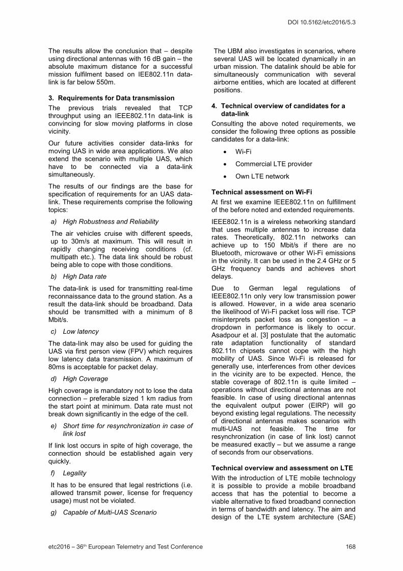
Figure 4 summarizes the requirements and fulfillment of assessed technologies for an UAS data-link. It comes clear that IEEE 802.11n does not satisfy our requirements. Therefore, we will evaluate LTE-based data-links as alternative solution. In the first step, commercial LTE-networks are examined here.
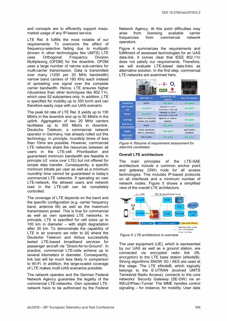
Overall LTE architecture The main principles of the LTE-SAE architecture include a common anchor point and gateway (GW) node for all access technologies. This includes IP-based protocols on all interfaces and a minimum number of network nodes. Figure 5 shows a simplified view of the overall LTE architecture.
The user equipment (UE), which is represented by our UAS as well as a ground station, are connected via encrypted radio link (RL encryption) to the LTE base station (eNodeB). Strong algorithms SNOW 3G / AES are used at this stage. The LTE eNodeB, which logically belongs to the E-UTRAN (evolved UMTS Terrestrial Radio Access), connects to the core networks’ Security Gateway (SE-GW) via an IKEv2/IPsec-Tunnel. The MME handles control signaling – for instance, for mobility. User data
Figure 4: Résumé of requirement assessment for data-link candidates
Figure 5: LTE-architecture in overview
etc2016 – 36th European Telemetry and Test Conference 170
DOI 10.5162/etc2016/5.3
is forwarded between base stations and gateway nodes over an IP-based transport infrastructure. The home subscriber server (HSS) stores configuration information (user specific entitlements) and the secret keys for simcard authentication, from where the keys for radio link encryption are derived.
The PDN gateway serves as a common anchor point for all access technologies, providing a stable IP point-of-presence for all users regardless of mobility within or between access technologies. The PDN-GW provides the access to the Internet where the PCRF (Policy and Charging Rules Function) controls connection parameters such as maximum bandwidth. A separate serving gateway (S-GW) is mandatory in roaming scenarios only. Otherwise, S-GW and PDN-GW functions are handled by the same network node.
5. Concept for UAS data-link based on commercial LTE-network
Due to limitations of available public IPv4-adresses, commercial LTE networks are configured to assign private IP-addresses to each UE most commonly. When analyzing the routes of IP-packets in these LTE networks we revealed that CG-NAT (carrier grade network access translation) is used twice for the packets. Consequently, services on UEs are not accessible from the internet and UEs are not able to communicate directly among each other. These restrictions preclude commercial LTE-networks as data-link for UAS at first.
We meet that challenges by building up own VPN-infrastructure (Virtual private Network). For this purpose, we configured a Linux-Ubuntu-server with openvpn. This server also manages the assignment of VPN-IP-addresses to UEs as well as routing between all connected UEs. As a consequence, all UEs are virtually located in the same network. Thereby, we overcome any restrictions in communication among each UEs and also relating to open ports. In addition, the communication is completely secured by strong encryption.
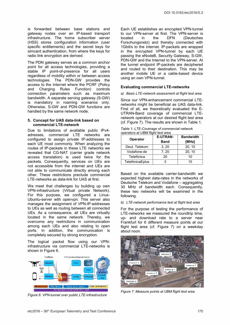
The logical packet flow using our VPN-infrastructure via commercial LTE-networks is shown in Figure 6.
Each UE establishes an encrypted VPN-tunnel to our VPN-server at first. The VPN-server is located in the DFN (Deutsches Forschungsnetz) and thereby connected with 1Gbit/s to the internet. IP-packets are wrapped in the encrypted VPN-tunnel by each UE passing the eNodeB, Security Gateway, S-GW, PDN-GW and the Internet to the VPN-server. At the tunnel endpoint IP-packets are deciphered and routed to their destination. This may be another mobile UE or a cable-based device using an own VPN-tunnel.
Evaluating commercial LTE-networks a) Basic LTE-network assessment at flight test area
Since our VPN-enhancement commercial LTE-networks might be beneficial as UAS data-link. First of all, we theoretically evaluated the E-UTRAN-Band coverage of commercial LTE-network operators at our desired flight test area (cf. Figure 7). The results are shown in Table 1. Table 1: LTE-Coverage of commercial network operators at UBM flight test area
Based on the available carrier-bandwidth we expected highest data-rates in the networks of Deutsche Telekom and Vodafone – aggregating 30 MHz of bandwidth each. Consequently, these two networks will be examined in the following. b) LTE-network performance test at flight test area
For the purpose of testing the performance of LTE-networks we measured the roundtrip time, up- and download rate to a server near Frankfurt for 6 different measure points at our flight test area (cf. Figure 7) on a weekday about noon.
Figure 6: VPN-tunnel over public LTE-infrastructure Figure 7: Measure points at UBM flight test area
etc2016 – 36th European Telemetry and Test Conference 171
DOI 10.5162/etc2016/5.3
As test equipment we used a Samsung Galaxy G900FD, which is capable of LTE Cat. 4. LTE-Advanced is not supported. The Results of our measures can be found in the following Table 2.
To start with, our measures are representative at a specific location and time only. They are not generally valid for the tested network operators. Table 2: Data rates for 2 network operators at measure points
At our flight test area we revealed transfer rates between 9…32.9 Mbit/s in Downlink (mean: 19.75Mbit/s) and 9…10.6 Mbit/s in Uplink (mean: 10.1 Mbit/s) for the Deutsche Telekom. The Uplink suffered from contractual limitations.
Vodafone transfers between 7…12 Mbit/s in Downlink (mean: 8.5 Mbit/s) and 0.5…6 Mbit/s in Upload (mean: 4 Mbit/s).
Both network operators provide roundtrips in an acceptable range. To sum up, in our measures at the flight test area the Deutsche Telekom provided much better data rates than Vodafone. Using a Vodafone network did not fulfil our requirement (b). Hence, we only regarded Deutsche Telekom for all further tests. c) Test of LTE-coverage in typical flight altitude
The next step comprised to prove evidence for LTE-coverage not only on ground level, but rather at typical flight altitude. This coverage mainly depends on the antenna tilt of the eNodeB. A typical flight altitude of our UAS is below 150 m AGL. Due to airspace regulations, altitudes above 150 m AGL are not allowed.
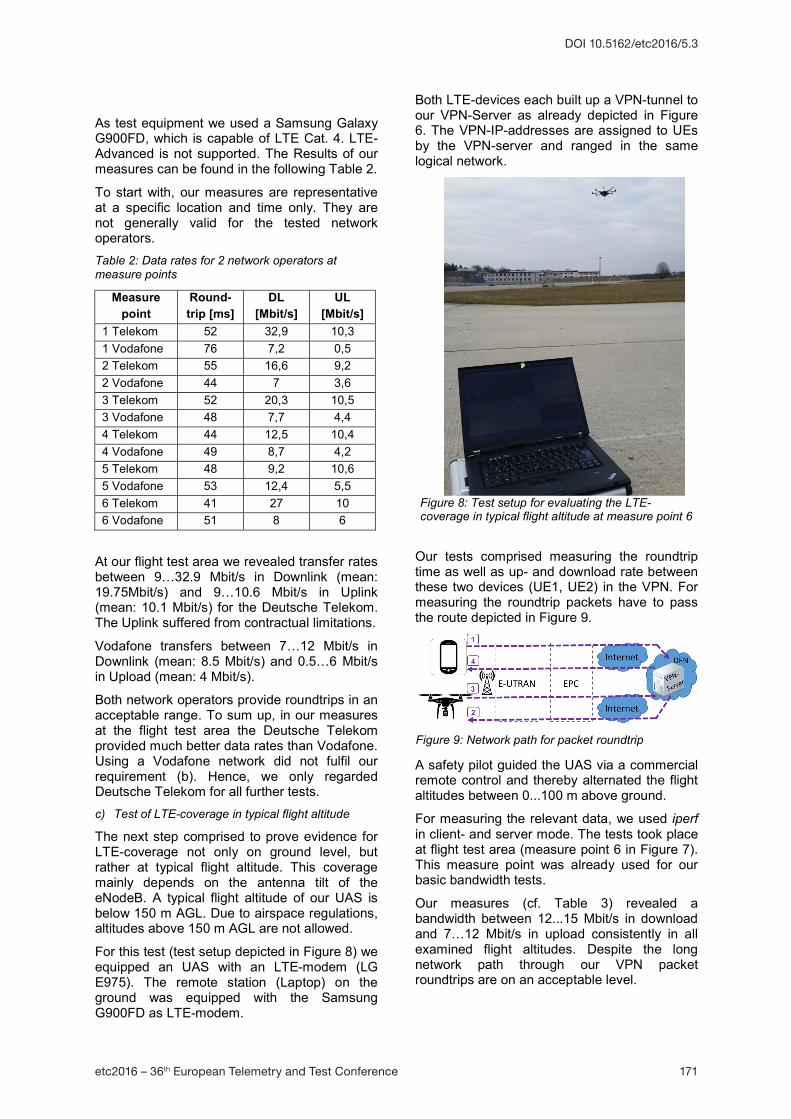
For this test (test setup depicted in Figure 8) we equipped an UAS with an LTE-modem (LG E975). The remote station (Laptop) on the ground was equipped with the Samsung G900FD as LTE-modem.
Both LTE-devices each built up a VPN-tunnel to our VPN-Server as already depicted in Figure 6. The VPN-IP-addresses are assigned to UEs by the VPN-server and ranged in the same logical network.
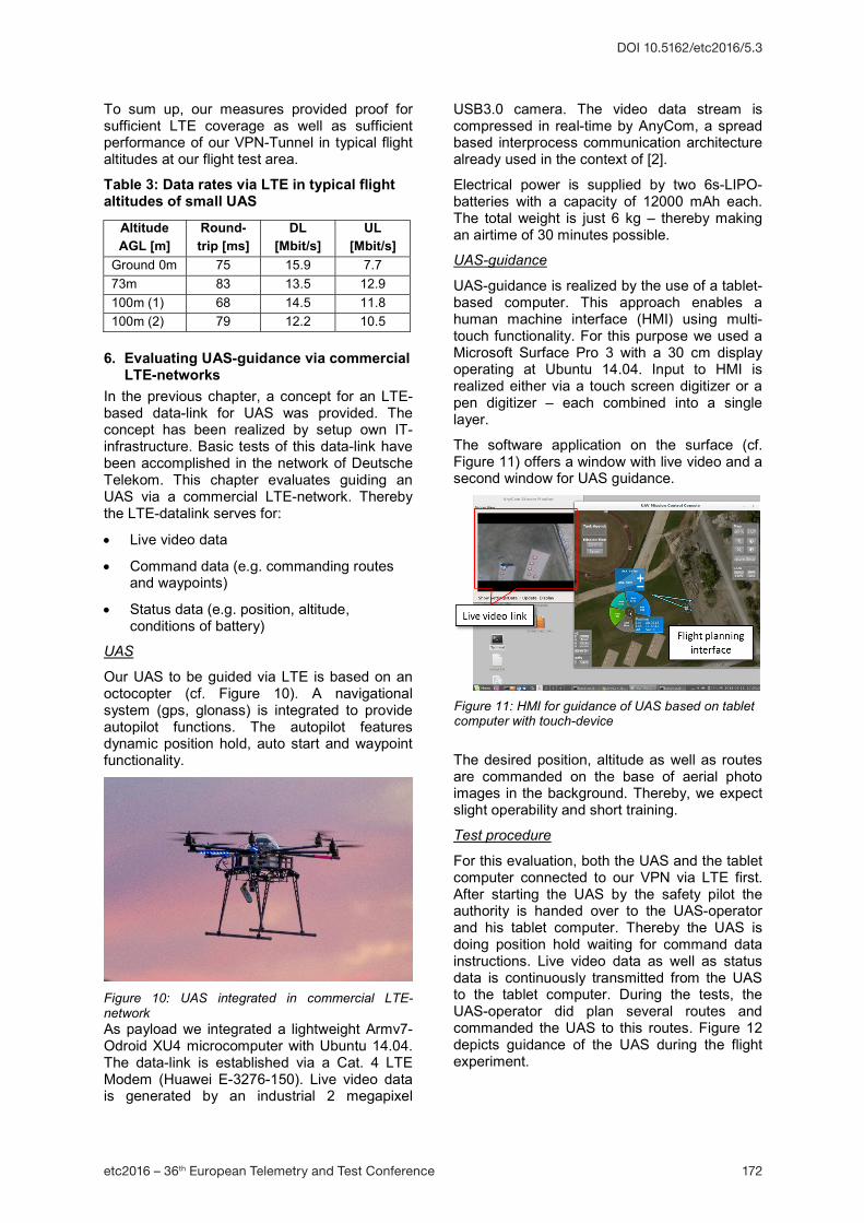
Our tests comprised measuring the roundtrip time as well as up- and download rate between these two devices (UE1, UE2) in the VPN. For measuring the roundtrip packets have to pass the route depicted in Figure 9.
A safety pilot guided the UAS via a commercial remote control and thereby alternated the flight altitudes between 0...100 m above ground.
For measuring the relevant data, we used iperf in client- and server mode. The tests took place at flight test area (measure point 6 in Figure 7). This measure point was already used for our basic bandwidth tests.
Our measures (cf. Table 3) revealed a bandwidth between 12...15 Mbit/s in download and 7…12 Mbit/s in upload consistently in all examined flight altitudes. Despite the long network path through our VPN packet roundtrips are on an acceptable level.
Figure 8: Test setup for evaluating the LTE-coverage in typical flight altitude at measure point 6
Figure 9: Network path for packet roundtrip
etc2016 – 36th European Telemetry and Test Conference 172
DOI 10.5162/etc2016/5.3
To sum up, our measures provided proof for sufficient LTE coverage as well as sufficient performance of our VPN-Tunnel in typical flight altitudes at our flight test area.
Table 3: Data rates via LTE in typical flight altitudes of small UAS
6. Evaluating UAS-guidance via commercial LTE-networks
In the previous chapter, a concept for an LTE-based data-link for UAS was provided. The concept has been realized by setup own IT-infrastructure. Basic tests of this data-link have been accomplished in the network of Deutsche Telekom. This chapter evaluates guiding an UAS via a commercial LTE-network. Thereby the LTE-datalink serves for:
Live video data
Command data (e.g. commanding routes and waypoints)
Status data (e.g. position, altitude, conditions of battery)
UAS
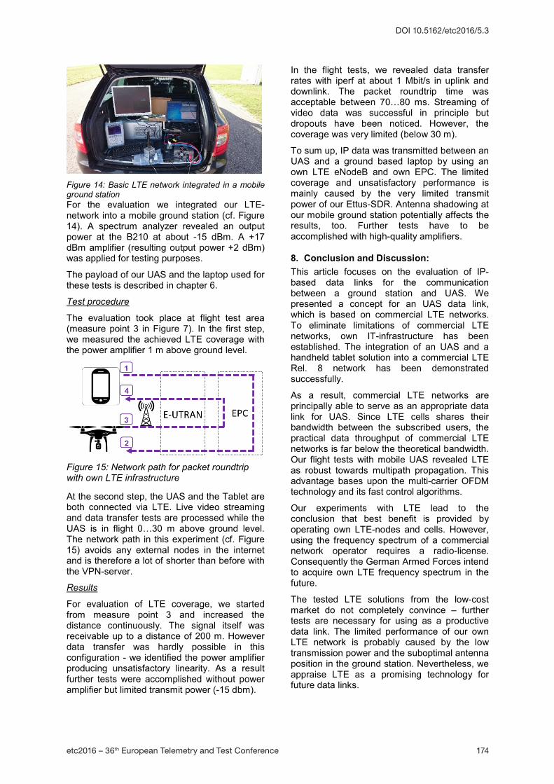
Our UAS to be guided via LTE is based on an octocopter (cf. Figure 10). A navigational system (gps, glonass) is integrated to provide autopilot functions. The autopilot features dynamic position hold, auto start and waypoint functionality.
Figure 10: UAS integrated in commercial LTE-network As payload we integrated a lightweight Armv7-Odroid XU4 microcomputer with Ubuntu 14.04. The data-link is established via a Cat. 4 LTE Modem (Huawei E-3276-150). Live video data is generated by an industrial 2 megapixel
USB3.0 camera. The video data stream is compressed in real-time by AnyCom, a spread based interprocess communication architecture already used in the context of [2].
Electrical power is supplied by two 6s-LIPO-batteries with a capacity of 12000 mAh each. The total weight is just 6 kg – thereby making an airtime of 30 minutes possible.
UAS-guidance
UAS-guidance is realized by the use of a tablet-based computer. This approach enables a human machine interface (HMI) using multi-touch functionality. For this purpose we used a Microsoft Surface Pro 3 with a 30 cm display operating at Ubuntu 14.04. Input to HMI is realized either via a touch screen digitizer or a pen digitizer – each combined into a single layer.
The software application on the surface (cf. Figure 11) offers a window with live video and a second window for UAS guidance.
The desired position, altitude as well as routes are commanded on the base of aerial photo images in the background. Thereby, we expect slight operability and short training.
Test procedure
For this evaluation, both the UAS and the tablet computer connected to our VPN via LTE first. After starting the UAS by the safety pilot the authority is handed over to the UAS-operator and his tablet computer. Thereby the UAS is doing position hold waiting for command data instructions. Live video data as well as status data is continuously transmitted from the UAS to the tablet computer. During the tests, the UAS-operator did plan several routes and commanded the UAS to this routes. Figure 12 depicts guidance of the UAS during the flight experiment.
Altitude AGL [m]
Round-trip [ms]
DL [Mbit/s]
UL [Mbit/s]
Ground 0m 75 15.9 7.7 73m 83 13.5 12.9 100m (1) 68 14.5 11.8 100m (2) 79 12.2 10.5
Figure 11: HMI for guidance of UAS based on tablet computer with touch-device
etc2016 – 36th European Telemetry and Test Conference 173
DOI 10.5162/etc2016/5.3
Results
The UAS successfully patrols on its commanded routes and waypoints. The maximum range tested was up to 500 m from the initial starting point (measure point 3). This was only due to legal constraints, which require eye sight to the UAS.
We noticed a smooth transmission of video data with a small delay via LTE. The quality of the video transmission was satisfactory. Eligible improvements in image quality could be realized via automatic image stabilization in the future. No link lost was observed.
7. First evaluation results of own LTE-network
In the previous chapter, we demonstrated the guidance of an UAS via commercial LTE-networks. In principle, this technique is sufficient to fulfill our requirements. However, commercial LTE is a shared medium between all subscribers in each of the cells. Thus without prioritization subscriber individual data-rates cannot be guaranteed.
The solution obviously offered here is to use own LTE infrastructure. Thereby, subscriber-management as well as bandwidth-management on the LTE-air interface is feasible. The UBM therefore investigates in the operation of own LTE infrastructure. This promising approach comprises building up an own EPC and an own eNodeB.
Such research activity is relevant for the German Armed Forces [5] as LTE may provide a military wideband data-link in the future – delivering lower latency, faster speeds and a more efficient architecture than the latest wireless military technologies. In this future scenario, a HALE-UAS (High Altitude Long Endurance) carries a LTE-based mobile hotspot to provide high-bandwidth communications for other UAS or ground troops in remote forward operating locations [6]. However, in our first LTE-trials, the LTE-nodes (eNodeB and EPC) both reside on a ground station.
Since commercial LTE equipment is designed for many thousands of subscribers and therefore cost intensive, we focused on small entry solutions. In the lower price segment, stand-alone solutions for a limited number of subscribers are offered integrating an eNodeB and an EPC in a single box. The signal generation is realized via software defined radio (SDR) and thus enables flexible operation in E-UTRAN-Bands.
Test equipment
For our LTE-trials, we used an Ettus B210 SDR (cf. Figure 13) as transceiver. This SDR is connected to a host computer through high-speed USB 3.0, which the host-based software uses to control the SDR hardware and transmit/receive data. The SDR covers a frequency range between 70 MHz to 6 GHz and provides the following subsystems: clock generation and synchronization, FPGA, ADCs, DACs, host processor interface, and power regulation. These are the basic components that are required for baseband processing of signals. A front-end daughterboard is used for analog operations such as up/down-conversion, filtering, and other signal conditioning.
Figure 13: ETTUS B210 SDR We use amarisoft [7] as host-based software to control the SDR. Amarisoft features an eNodeB compliant to LTE rel.8 and offers standard S1 and GTP-U interfaces to the core network. The bandwidth and target E-UTRAN-band are fully configurable. The amarisoft core network (EPC) implements one MME with built-in SGW, PGW and HSS. It supports several eNodeBs with standard S1 interface. Hence our basic LTE-network consists of the B210, the amarisoft eNodeB and EPC which grant access to IP network.
Evaluation setup
We configured our basic LTE-network to operate at SISO 2.6 GHz and 20 MHz bandwidth. The radio license at 2.6 GHz was gratefully provided by Deutsche Telekom.
Figure 12: UAS-guidance by tablet computer via LTE
etc2016 – 36th European Telemetry and Test Conference 174
DOI 10.5162/etc2016/5.3
Figure 14: Basic LTE network integrated in a mobile ground station For the evaluation we integrated our LTE-network into a mobile ground station (cf. Figure 14). A spectrum analyzer revealed an output power at the B210 at about -15 dBm. A +17 dBm amplifier (resulting output power +2 dBm) was applied for testing purposes.
The payload of our UAS and the laptop used for these tests is described in chapter 6.
Test procedure
The evaluation took place at flight test area (measure point 3 in Figure 7). In the first step, we measured the achieved LTE coverage with the power amplifier 1 m above ground level.
At the second step, the UAS and the Tablet are both connected via LTE. Live video streaming and data transfer tests are processed while the UAS is in flight 0…30 m above ground level. The network path in this experiment (cf. Figure 15) avoids any external nodes in the internet and is therefore a lot of shorter than before with the VPN-server.
Results
For evaluation of LTE coverage, we started from measure point 3 and increased the distance continuously. The signal itself was receivable up to a distance of 200 m. However data transfer was hardly possible in this configuration - we identified the power amplifier producing unsatisfactory linearity. As a result further tests were accomplished without power amplifier but limited transmit power (-15 dbm).
In the flight tests, we revealed data transfer rates with iperf at about 1 Mbit/s in uplink and downlink. The packet roundtrip time was acceptable between 70…80 ms. Streaming of video data was successful in principle but dropouts have been noticed. However, the coverage was very limited (below 30 m).
To sum up, IP data was transmitted between an UAS and a ground based laptop by using an own LTE eNodeB and own EPC. The limited coverage and unsatisfactory performance is mainly caused by the very limited transmit power of our Ettus-SDR. Antenna shadowing at our mobile ground station potentially affects the results, too. Further tests have to be accomplished with high-quality amplifiers.
8. Conclusion and Discussion: This article focuses on the evaluation of IP-based data links for the communication between a ground station and UAS. We presented a concept for an UAS data link, which is based on commercial LTE networks. To eliminate limitations of commercial LTE networks, own IT-infrastructure has been established. The integration of an UAS and a handheld tablet solution into a commercial LTE Rel. 8 network has been demonstrated successfully.
As a result, commercial LTE networks are principally able to serve as an appropriate data link for UAS. Since LTE cells shares their bandwidth between the subscribed users, the practical data throughput of commercial LTE networks is far below the theoretical bandwidth. Our flight tests with mobile UAS revealed LTE as robust towards multipath propagation. This advantage bases upon the multi-carrier OFDM technology and its fast control algorithms.
Our experiments with LTE lead to the conclusion that best benefit is provided by operating own LTE-nodes and cells. However, using the frequency spectrum of a commercial network operator requires a radio-license. Consequently the German Armed Forces intend to acquire own LTE frequency spectrum in the future.
The tested LTE solutions from the low-cost market do not completely convince – further tests are necessary for using as a productive data link. The limited performance of our own LTE network is probably caused by the low transmission power and the suboptimal antenna position in the ground station. Nevertheless, we appraise LTE as a promising technology for future data links.
Figure 15: Network path for packet roundtrip with own LTE infrastructure
etc2016 – 36th European Telemetry and Test Conference 175
[2] F. Böhm, A. Schulte. Scalable COTS based data processing and distribution architecture for UAV technology demonstrators. European Telemetry and Test Conference etc2012. Munich, Germany. 12-14 June 2012.
[3] M. Asadpour, D. Giustiniano, K. A. Hummel, and S. Heimlicher, “Characterizing 802.11n aerial communication”, ANC 2013.
[4] Tweet: Breitbanddienste für Passagierflugzeuge über ein “LTE-Direct-Air-to-Ground”. https://www.telekom.com/medien/ konzern/107624
[5] Tweet: Tetra-LTE-Pilotsystem von Airbus für die Bundeswehr. http://www.airbusgroup.com/int/en/news-media/press-releases/Airbus-Group/Financial_Communication/2014/12/20141204_airbus_defence_and_space_tetra_lte_bundeswehr/de_20141204_airbus_defence_and_space_tetra_lte_bundeswehr.html
[6] S. Malisuwan & W. Kaewphanuekrungsi. Ad Hoc UAV LTE Networks for Critical Communications. In International Journal of Computer Networking, Vol. 6(1), 2016, ISSN(E): 2278-9448