Using NEMOH for Modelling Wave Energy Converters: A Comparative Study with WAMIT Markel Penalba 1 , Thomas Kelly 2 and John V. Ringwood 3 Centre for Ocean Energy Research (COER), Maynooth University, Co.Kildare, Ireland [email protected]1 [email protected]2 [email protected]3 Abstract—Despite the well-known limitations of linear poten- tial flow theory, hydrodynamic coefficients obtained from boun- dary element methods (BEM) are commonly used to estimate the hydrodynamic parameters of wave energy converters (WECs). These parameters may then be used to simulate the behaviour of WECs in response to incident waves. In this work, the usefulness to the wave energy community of the open-source BEM solver, NEMOH, developed by the ´ Ecole Centrale de Nantes, is independently considered by comparison with the commercially-available BEM solver, WAMIT. The pre-processing, processing and post-processing stages of analysing four typical wave energy converting concepts are considered. Results for both solvers are presented in both the frequency and time domains. Other issues considered include computational time taken by both solvers, mesh generation, user-friendliness and the availability of supporting documentation. Index Terms—Wave energy, boundary element method solvers, WAMIT, NEMOH, hydrodynamic coefficients I. I NTRODUCTION Techniques to numerically simulate the behaviour of WECs in response to ocean waves are critical to the development of a wave energy industry. Numerical models may be used to predict the motions of, forces acting on and power output from a WEC. Such models may also be used as input to power take-off system models, proposed control strategy models, and financial models. Obtaining results from numerical modelling is typically significantly less expensive than deriving the equi- valent results from physical scale models using tank testing. BEM is perhaps the most common method used in the wave energy context. While limited by the linear nature of potential flow theory, the speed with which numerical simulation may be performed when compared to other simulation methods, such as computational fluid dynamics (CFD) or smoothed- particle hydrodynamics (SPH), makes BEM a common choice for early-stage device development. In this paper, a comparison is made between key device parameters, for a number of typical WEC concepts, obtained using the well-established, commercial BEM solver, WAMIT, and a recently-released, open-source BEM solver, NEMOH. BEM techniques are first introduced. A number of commercial BEM solvers are presented, as is the open-source solver. The relative usage by the wave energy community of each solver is estimated based on a survey of the number of references to each solver in the Proceedings of the 11th European Wave and Tidal Energy Conference [1]. This survey provided the rationale for considering WAMIT as the commercial solver of choice. Further, the choice of which four WEC concepts to compare is also informed by this survey. WAMIT and NEMOH are then compared under three he- adings. Firstly, the pre-processing stage for both solvers is compared with regard to the user interface, available docu- mentation and user-friendliness of pre-processing. Particular regard is given to the means by which the geometry under analysis is described through a process of mesh generation. Secondly, the processing stage, wherein the solver analyses the geometry in question, is compared for the two solvers. A comparison between the key parameters obtained by the processors for the four WEC concepts considered in both the frequency and time domains are presented in graph and tabular form. Further, consideration is also given to the processing time required by each solver. In the final stage of the study, the use of the results from both solvers with third party post- processors is compared. The paper concludes with a discussion of the benefits and disadvantages of the use of both solvers for the analysis of different WEC concepts, as determined during this study. II. BOUNDARY ELEMENT METHOD BEM, also known as the panel method, is a numerical technique which uses systems of partial differential equati- ons formulated into the boundary integral form. BEM codes employ the method of Green’s functions to transform a flow problem into a problem of source distribution on the body surface [3]. BEM codes may be applied to varying engineering problems, and when used in a hydrodynamic context, BEM is used to solve for the scatter and radiated velocity potentials, which are solved separately and which arise from the inte- raction of a harmonic linear wave field with a body located within that field. The scattering potential is solved for the body when it is held fixed, and may be used to determine the exciting force acting on the body due to the wave action. The radiating potential, wherein the potential is found for a moving body in the absence of incident waves, is commonly resolved into components in phase with the body acceleration and the body velocity, and gives rise to the added-mass and radiation damping terms. A number of commercial software codes have been de- veloped to implement BEM to determine the hydrodynamic parameters of user-generated geometries. Such codes include WAMIT, Aquaplus, Aqwa and WADAM, all of which are
Transcript
Using NEMOH for Modelling Wave EnergyConverters: A Comparative Study with WAMIT
Markel Penalba1, Thomas Kelly2 and John V. Ringwood3Centre for Ocean Energy Research (COER), Maynooth University, Co.Kildare, Ireland
Abstract—Despite the well-known limitations of linear poten-tial flow theory, hydrodynamic coefficients obtained from boun-dary element methods (BEM) are commonly used to estimate thehydrodynamic parameters of wave energy converters (WECs).These parameters may then be used to simulate the behaviourof WECs in response to incident waves. In this work, theusefulness to the wave energy community of the open-sourceBEM solver, NEMOH, developed by the Ecole Centrale deNantes, is independently considered by comparison with thecommercially-available BEM solver, WAMIT. The pre-processing,processing and post-processing stages of analysing four typicalwave energy converting concepts are considered. Results for bothsolvers are presented in both the frequency and time domains.Other issues considered include computational time taken by bothsolvers, mesh generation, user-friendliness and the availability ofsupporting documentation.
Index Terms—Wave energy, boundary element method solvers,WAMIT, NEMOH, hydrodynamic coefficients
I. INTRODUCTION
Techniques to numerically simulate the behaviour of WECsin response to ocean waves are critical to the developmentof a wave energy industry. Numerical models may be usedto predict the motions of, forces acting on and power outputfrom a WEC. Such models may also be used as input to powertake-off system models, proposed control strategy models, andfinancial models. Obtaining results from numerical modellingis typically significantly less expensive than deriving the equi-valent results from physical scale models using tank testing.BEM is perhaps the most common method used in the waveenergy context. While limited by the linear nature of potentialflow theory, the speed with which numerical simulation maybe performed when compared to other simulation methods,such as computational fluid dynamics (CFD) or smoothed-particle hydrodynamics (SPH), makes BEM a common choicefor early-stage device development.
In this paper, a comparison is made between key deviceparameters, for a number of typical WEC concepts, obtainedusing the well-established, commercial BEM solver, WAMIT,and a recently-released, open-source BEM solver, NEMOH.BEM techniques are first introduced. A number of commercialBEM solvers are presented, as is the open-source solver. Therelative usage by the wave energy community of each solveris estimated based on a survey of the number of referencesto each solver in the Proceedings of the 11th European Waveand Tidal Energy Conference [1]. This survey provided therationale for considering WAMIT as the commercial solver of
choice. Further, the choice of which four WEC concepts tocompare is also informed by this survey.
WAMIT and NEMOH are then compared under three he-adings. Firstly, the pre-processing stage for both solvers iscompared with regard to the user interface, available docu-mentation and user-friendliness of pre-processing. Particularregard is given to the means by which the geometry underanalysis is described through a process of mesh generation.
Secondly, the processing stage, wherein the solver analysesthe geometry in question, is compared for the two solvers.A comparison between the key parameters obtained by theprocessors for the four WEC concepts considered in both thefrequency and time domains are presented in graph and tabularform. Further, consideration is also given to the processingtime required by each solver. In the final stage of the study,the use of the results from both solvers with third party post-processors is compared.
The paper concludes with a discussion of the benefits anddisadvantages of the use of both solvers for the analysis ofdifferent WEC concepts, as determined during this study.
II. BOUNDARY ELEMENT METHOD
BEM, also known as the panel method, is a numericaltechnique which uses systems of partial differential equati-ons formulated into the boundary integral form. BEM codesemploy the method of Green’s functions to transform a flowproblem into a problem of source distribution on the bodysurface [3]. BEM codes may be applied to varying engineeringproblems, and when used in a hydrodynamic context, BEM isused to solve for the scatter and radiated velocity potentials,which are solved separately and which arise from the inte-raction of a harmonic linear wave field with a body locatedwithin that field. The scattering potential is solved for thebody when it is held fixed, and may be used to determinethe exciting force acting on the body due to the wave action.The radiating potential, wherein the potential is found for amoving body in the absence of incident waves, is commonlyresolved into components in phase with the body accelerationand the body velocity, and gives rise to the added-mass andradiation damping terms.
A number of commercial software codes have been de-veloped to implement BEM to determine the hydrodynamicparameters of user-generated geometries. Such codes includeWAMIT, Aquaplus, Aqwa and WADAM, all of which are
TABLE I: The Available BEM Solvers and their Characteristics
BEMsolver
Frequencydomain
Timedomain
Opensource
Usage[%]∗ Arrays∗ Point
Absorber∗ OWC∗ OWSC∗ Other∗ Time domainsimulation∗
∗ Statistics are based on the publications in [1], where 14.2% of the publications referenced a BEM solver.
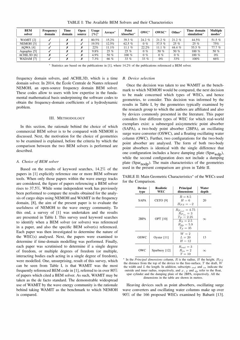
frequency domain solvers, and ACHIL3D, which is a timedomain solver. In 2014, the Ecole Centrale de Nantes releasedNEMOH, an open-source frequency domain BEM solver.These codes allow to users with low expertise in the funda-mental mathematical basis underpinning the software codes toobtain the frequency-domain coefficients of a hydrodynamicproblem.
III. METHODOLOGY
In this section, the rationale behind the choice of whichcommercial BEM solver is to be compared with NEMOH isdiscussed. Next, the motivation for the choice of geometriesto be examined is explained, before the criteria by which thecomparison between the two BEM solvers is performed aredescribed.
A. Choice of BEM solver
Based on the results of keyword searches, 14.2% of thepapers in [1] explicitly reference one or more BEM softwaretools. When only those papers within the wave energy tracksare considered, the figure of papers referencing a BEM solverrises to 37.5%. While some independent work has previouslybeen performed to compare the results obtained for the analy-sis of cargo ships using NEMOH and WAMIT in the frequencydomain, [8], the aim of the present paper is to evaluate theusefulness of NEMOH to the wave energy community. Tothis end, a survey of [1] was undertaken and the resultsare presented in Table I. This survey used keyword searchesto identify when a BEM solver (or solvers) was referencedin a paper, and also the specific BEM solver(s) referenced.Each paper was then investigated to determine the nature ofthe WEC(s) analysed. Next, the papers were examined todetermine if time-domain modelling was performed. Finally,each paper was scrutinised to determine if a single degreeof freedom, or multiple degrees of freedom (or multiple,interacting bodies each acting in a single degree of freedom),were modelled. One, unsurprising, result of this survey, whichcan be seen from Table I, is that WAMIT was the mostfrequently referenced BEM code in [1], referred to in over 80%of papers which cited a BEM solver. As such, WAMIT may betaken as the de facto standard. The demonstrable widespreaduse of WAMIT by the wave energy community is the rationalebehind taking WAMIT as the benchmark to which NEMOHis compared.
B. Device selection
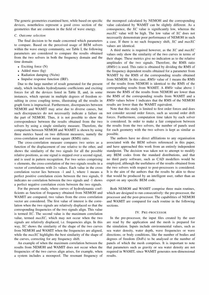
Once the decision was taken to use WAMIT as the bench-mark to which NEMOH would be compared, the next decisionto be made concerned which types of WECs, and hencegeometries, to consider. This decision was informed by theresults in Table I, by the geometries typically examined bythe research group to which the authors are affiliated and alsoby devices commonly presented in the literature. This paperconsiders four different types of WEC for which real-worldexemplars exist: a submerged axisymmetric point absorber(SAPA), a two-body point absorber (2BPA), an oscillatingsurge wave converter (OSWC), and a floating oscillating watercolumn (OWC). Further, two configurations for the two-bodypoint absorber are analysed. The form of both two-bodypoint absorbers is identical with the single difference thatone configuration includes a heave damping plate (Sparwdp),while the second configuration does not include a dampingplate (Sparnodp). The main characteristics of the geometriesused in the present comparison are given in Table II.
TABLE II: Main Geometric Characteristics∗ of the WECs usedfor the Comparison.
Devicetype
RealisticWEC
Principaldimensions
Waterdepth
SAPA CETO [9]R = 8.5
20H = 6HFS = −2
2BPA OPT [10]
RFout = 4.75
∞RFin
= 3TF = 2.25RS = 2.5Rdp = 5.9TS = 35
OSWC Oyster [11]W = 2
13L = 20H = 12
OWC Sparbuoy [12]Rout = 3
∞Rin = 2T = 10
∗ In the Principal dimensions column, R is the radius, H the height, HFS
the distance from the top of the device to the free-surface, T the draft, Wthe width and L the length. In addition, subscripts out and in indicate theoutside and inner radius, respectively, and F , S and dp refer to the float,
spar cylinder and the damping plate of the 2BPA, respectively. All thedimensions in the table are shown in metres.
Heaving devices such as point absorbers, oscillating surgewave converters and oscillating water columns make up over90% of the 166 proposed WECs examined by Babarit [13].
The generic geometries examined here, while based on specificdevices, nonetheless represent a good cross section of thegeometries that are common in the field of wave energy.
C. Outcome selection
The final decision to be made concerned which parametersto compare. Based on the perceived usage of BEM solverswithin the wave energy community, see Table I, the followingparameters are considered to compare the results obtainedfrom the two solvers in both the frequency domain and thetime domain:• Exciting force (N)• Added mass (kg)• Radiation damping (Ns/m)• Impulse response function (IRF).Due to the large number of result generated for the present
study, which includes hydrodynamic coefficients and excitingforces for all the devices listed in Table II, and, in someinstances, which operate in multiple degrees of freedom re-sulting in cross coupling terms, illustrating all the results ingraph form is impractical. Furthermore, discrepancies betweenNEMOH and WAMIT may arise due to diverse causes, butsuch discrepancies do not necessarily indicate a failure onthe part of NEMOH. Thus, it is not possible to show thecorrespondence between the results obtained from the twosolvers by using a single similarity measure. Therefore, thecomparison between NEMOH and WAMIT is shown by usingthree metrics based on two different measures, namely thecross-correlation and root mean square (RMS) ratio.
The cross-correlation measure compares two series as afunction of the displacement of one relative to the other, andshows the similarity of the two signals for all the possiblerelative positions, as one signal is stepped over a second signal,and is used in pattern recognition. For two series comprisingn elements, the cross-correlation of the two signals results in avector of correlations with 2n values. Each value in the crosscorrelation vector lies between -1 and 1, where 1 means aperfect positive correlation exists between the two signals, 0indicates no correlation between the two signals and -1 showsa perfect negative correlation exists between the two signals.
For the present study, where curves of hydrodynamic coef-ficients as function of frequency obtained from NEMOH andWAMIT are compared, two values from the cross correlationvector are considered. The first value of interest is the corre-lation when the two signals are relatively displaced so that thecorresponding frequencies of the two signals align. This valueis termed XC. The second value is the maximum correlationvalue, termed maxXC, which may not occur when the twosignals are relatively displaced, i.e. frequencies align. In thisway, XC shows the similarity of the shape of the two curvesfrom NEMOH and WAMIT when the frequencies are aligned,while the maxXC highlights the best similarity of the shape ofthe curves, correcting for any frequency shift.
An example of when the maximum correlation between theresults from NEMOH and WAMIT does not occur when thefrequencies of the two curves align arises, for example, whena system includes a moonpool. The resonant frequency of
the moonpool calculated by NEMOH and the correspondingvalue calculated by WAMIT can be slightly different. As aconsequence, the XC value is significantly low, whereas themaxXC value will be high. The low value of XC does notnecessarily demonstrate poor performance of NEMOH in sucha case. If there is no such frequency shift, XC and maxXCvalues are identical.
A third metric is required however, as the XC and maxXCvalues only show the similarity of the two curves in terms oftheir shape. These metrics give no indication as to the relativeamplitudes of the two signals. Therefore, the RMS ratio(RMSr) is used. This ratio is obtained by dividing the RMS ofthe frequency dependent results obtained for a parameter fromWAMIT by the RMS of the corresponding results obtainedfrom NEMOH. In this case, RMSr value of 1 means the RMSof the results from NEMOH is identical to the RMS of thecorresponding results from WAMIT. A RMSr value above 1means the RMS of the results from NEMOH are lower thanthe RMS of the corresponding results from WAMIT and aRMSr values below 1 indicates that the RMS of the NEMOHresults are lower than the WAMIT equivalent.
Note that this study is limited to first order forces and doesnot consider second order forces, such as second order driftforces. Furthermore, computation time taken by each solveris considered. In order to make a fair comparison betweenthe results from the two solvers, the number of panels usedfor each geometry with the two solvers is kept as similar aspossible.
The authors have no direct affiliations to any organisationassociated with the BEM solvers referenced in this paper,and have approached this work from an entirely independentstandpoint. The decision was taken not to attempt to modifyany BEM codes from the standard distributions, and thatno third party software, such as CAD modellers would beemployed, although the usefulness of the results obtained fromthe two solvers with respect to post-processors is considered.It is the aim of the authors that the results be akin to thosethat would be produced by an intelligent user, rather than anexpert on any specific BEM code.
Both NEMOH and WAMIT comprise three main routines,which are designed to run consecutively: the pre-processor, theprocessor and the post-processor. The capabilities of NEMOHand WAMIT are compared for each routine in the followingsections.
IV. PRE-PROCESSOR
In the pre-processor, the input files created by the userare read by the application and the mesh is prepared forthe simulation. Inputs include environmental values, such assea water density, water depth, wave frequencies or wavedirections; or body conditions, like the number of bodies anddegrees of freedom (DoFs) to be analysed or the number ofpanels of which the mesh comprises. It is important to notethat parameters such as gravity or sea water density are notrequired in WAMIT, since WAMIT generates non-dimensionalresults.
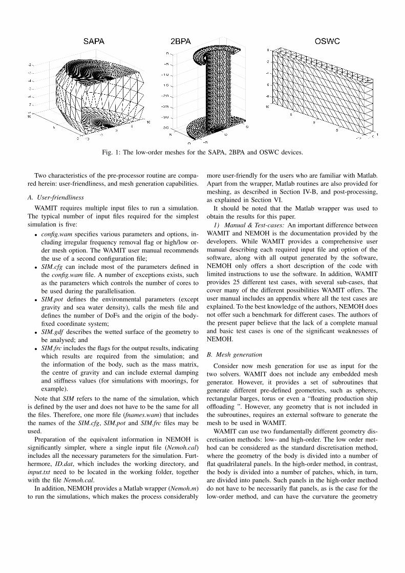
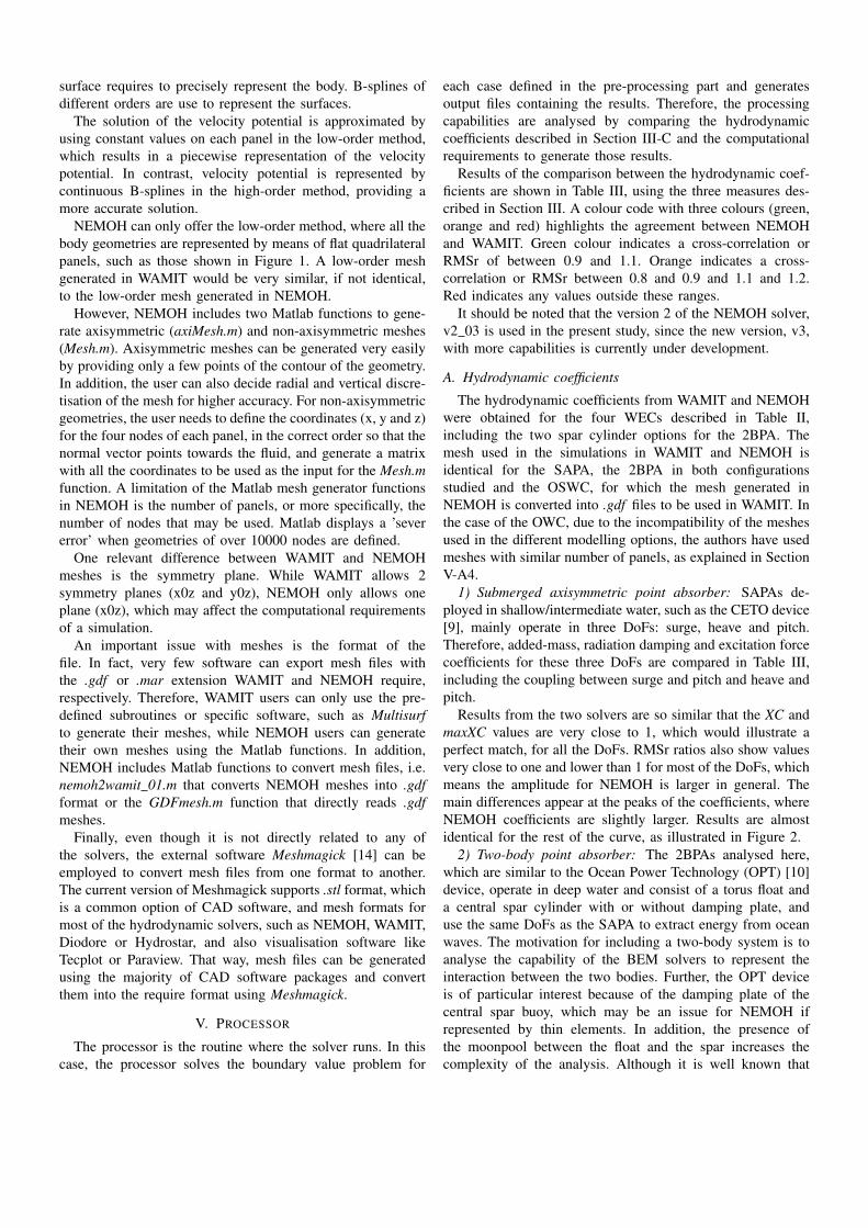
Fig. 1: The low-order meshes for the SAPA, 2BPA and OSWC devices.
Two characteristics of the pre-processor routine are compa-red herein: user-friendliness, and mesh generation capabilities.
A. User-friendliness
WAMIT requires multiple input files to run a simulation.The typical number of input files required for the simplestsimulation is five:• config.wam specifies various parameters and options, in-
cluding irregular frequency removal flag or high/low or-der mesh option. The WAMIT user manual recommendsthe use of a second configuration file;
• SIM.cfg can include most of the parameters defined inthe config.wam file. A number of exceptions exists, suchas the parameters which controls the number of cores tobe used during the parallelisation.
• SIM.pot defines the environmental parameters (exceptgravity and sea water density), calls the mesh file anddefines the number of DoFs and the origin of the body-fixed coordinate system;
• SIM.gdf describes the wetted surface of the geometry tobe analysed; and
• SIM.frc includes the flags for the output results, indicatingwhich results are required from the simulation; andthe information of the body, such as the mass matrix,the centre of gravity and can include external dampingand stiffness values (for simulations with moorings, forexample).
Note that SIM refers to the name of the simulation, whichis defined by the user and does not have to be the same for allthe files. Therefore, one more file (fnames.wam) that includesthe names of the SIM.cfg, SIM.pot and SIM.frc files may beused.
Preparation of the equivalent information in NEMOH issignificantly simpler, where a single input file (Nemoh.cal)includes all the necessary parameters for the simulation. Furt-hermore, ID.dat, which includes the working directory, andinput.txt need to be located in the working folder, togetherwith the file Nemoh.cal.
In addition, NEMOH provides a Matlab wrapper (Nemoh.m)to run the simulations, which makes the process considerably
more user-friendly for the users who are familiar with Matlab.Apart from the wrapper, Matlab routines are also provided formeshing, as described in Section IV-B, and post-processing,as explained in Section VI.
It should be noted that the Matlab wrapper was used toobtain the results for this paper.
1) Manual & Test-cases: An important difference betweenWAMIT and NEMOH is the documentation provided by thedevelopers. While WAMIT provides a comprehensive usermanual describing each required input file and option of thesoftware, along with all output generated by the software,NEMOH only offers a short description of the code withlimited instructions to use the software. In addition, WAMITprovides 25 different test cases, with several sub-cases, thatcover many of the different possibilities WAMIT offers. Theuser manual includes an appendix where all the test cases areexplained. To the best knowledge of the authors, NEMOH doesnot offer such a benchmark for different cases. The authors ofthe present paper believe that the lack of a complete manualand basic test cases is one of the significant weaknesses ofNEMOH.
B. Mesh generation
Consider now mesh generation for use as input for thetwo solvers. WAMIT does not include any embedded meshgenerator. However, it provides a set of subroutines thatgenerate different pre-defined geometries, such as spheres,rectangular barges, torus or even a “floating production shipoffloading ”. However, any geometry that is not included inthe subroutines, requires an external software to generate themesh to be used in WAMIT.
WAMIT can use two fundamentally different geometry dis-cretisation methods: low- and high-order. The low order met-hod can be considered as the standard discretisation method,where the geometry of the body is divided into a number offlat quadrilateral panels. In the high-order method, in contrast,the body is divided into a number of patches, which, in turn,are divided into panels. Such panels in the high-order methoddo not have to be necessarily flat panels, as is the case for thelow-order method, and can have the curvature the geometry
surface requires to precisely represent the body. B-splines ofdifferent orders are use to represent the surfaces.
The solution of the velocity potential is approximated byusing constant values on each panel in the low-order method,which results in a piecewise representation of the velocitypotential. In contrast, velocity potential is represented bycontinuous B-splines in the high-order method, providing amore accurate solution.
NEMOH can only offer the low-order method, where all thebody geometries are represented by means of flat quadrilateralpanels, such as those shown in Figure 1. A low-order meshgenerated in WAMIT would be very similar, if not identical,to the low-order mesh generated in NEMOH.
However, NEMOH includes two Matlab functions to gene-rate axisymmetric (axiMesh.m) and non-axisymmetric meshes(Mesh.m). Axisymmetric meshes can be generated very easilyby providing only a few points of the contour of the geometry.In addition, the user can also decide radial and vertical discre-tisation of the mesh for higher accuracy. For non-axisymmetricgeometries, the user needs to define the coordinates (x, y and z)for the four nodes of each panel, in the correct order so that thenormal vector points towards the fluid, and generate a matrixwith all the coordinates to be used as the input for the Mesh.mfunction. A limitation of the Matlab mesh generator functionsin NEMOH is the number of panels, or more specifically, thenumber of nodes that may be used. Matlab displays a ’severerror’ when geometries of over 10000 nodes are defined.
One relevant difference between WAMIT and NEMOHmeshes is the symmetry plane. While WAMIT allows 2symmetry planes (x0z and y0z), NEMOH only allows oneplane (x0z), which may affect the computational requirementsof a simulation.
An important issue with meshes is the format of thefile. In fact, very few software can export mesh files withthe .gdf or .mar extension WAMIT and NEMOH require,respectively. Therefore, WAMIT users can only use the pre-defined subroutines or specific software, such as Multisurfto generate their meshes, while NEMOH users can generatetheir own meshes using the Matlab functions. In addition,NEMOH includes Matlab functions to convert mesh files, i.e.nemoh2wamit 01.m that converts NEMOH meshes into .gdfformat or the GDFmesh.m function that directly reads .gdfmeshes.
Finally, even though it is not directly related to any ofthe solvers, the external software Meshmagick [14] can beemployed to convert mesh files from one format to another.The current version of Meshmagick supports .stl format, whichis a common option of CAD software, and mesh formats formost of the hydrodynamic solvers, such as NEMOH, WAMIT,Diodore or Hydrostar, and also visualisation software likeTecplot or Paraview. That way, mesh files can be generatedusing the majority of CAD software packages and convertthem into the require format using Meshmagick.
V. PROCESSOR
The processor is the routine where the solver runs. In thiscase, the processor solves the boundary value problem for
each case defined in the pre-processing part and generatesoutput files containing the results. Therefore, the processingcapabilities are analysed by comparing the hydrodynamiccoefficients described in Section III-C and the computationalrequirements to generate those results.
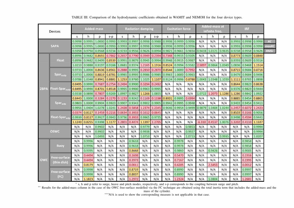
Results of the comparison between the hydrodynamic coef-ficients are shown in Table III, using the three measures des-cribed in Section III. A colour code with three colours (green,orange and red) highlights the agreement between NEMOHand WAMIT. Green colour indicates a cross-correlation orRMSr of between 0.9 and 1.1. Orange indicates a cross-correlation or RMSr between 0.8 and 0.9 and 1.1 and 1.2.Red indicates any values outside these ranges.
It should be noted that the version 2 of the NEMOH solver,v2 03 is used in the present study, since the new version, v3,with more capabilities is currently under development.
A. Hydrodynamic coefficients
The hydrodynamic coefficients from WAMIT and NEMOHwere obtained for the four WECs described in Table II,including the two spar cylinder options for the 2BPA. Themesh used in the simulations in WAMIT and NEMOH isidentical for the SAPA, the 2BPA in both configurationsstudied and the OSWC, for which the mesh generated inNEMOH is converted into .gdf files to be used in WAMIT. Inthe case of the OWC, due to the incompatibility of the meshesused in the different modelling options, the authors have usedmeshes with similar number of panels, as explained in SectionV-A4.
1) Submerged axisymmetric point absorber: SAPAs de-ployed in shallow/intermediate water, such as the CETO device[9], mainly operate in three DoFs: surge, heave and pitch.Therefore, added-mass, radiation damping and excitation forcecoefficients for these three DoFs are compared in Table III,including the coupling between surge and pitch and heave andpitch.
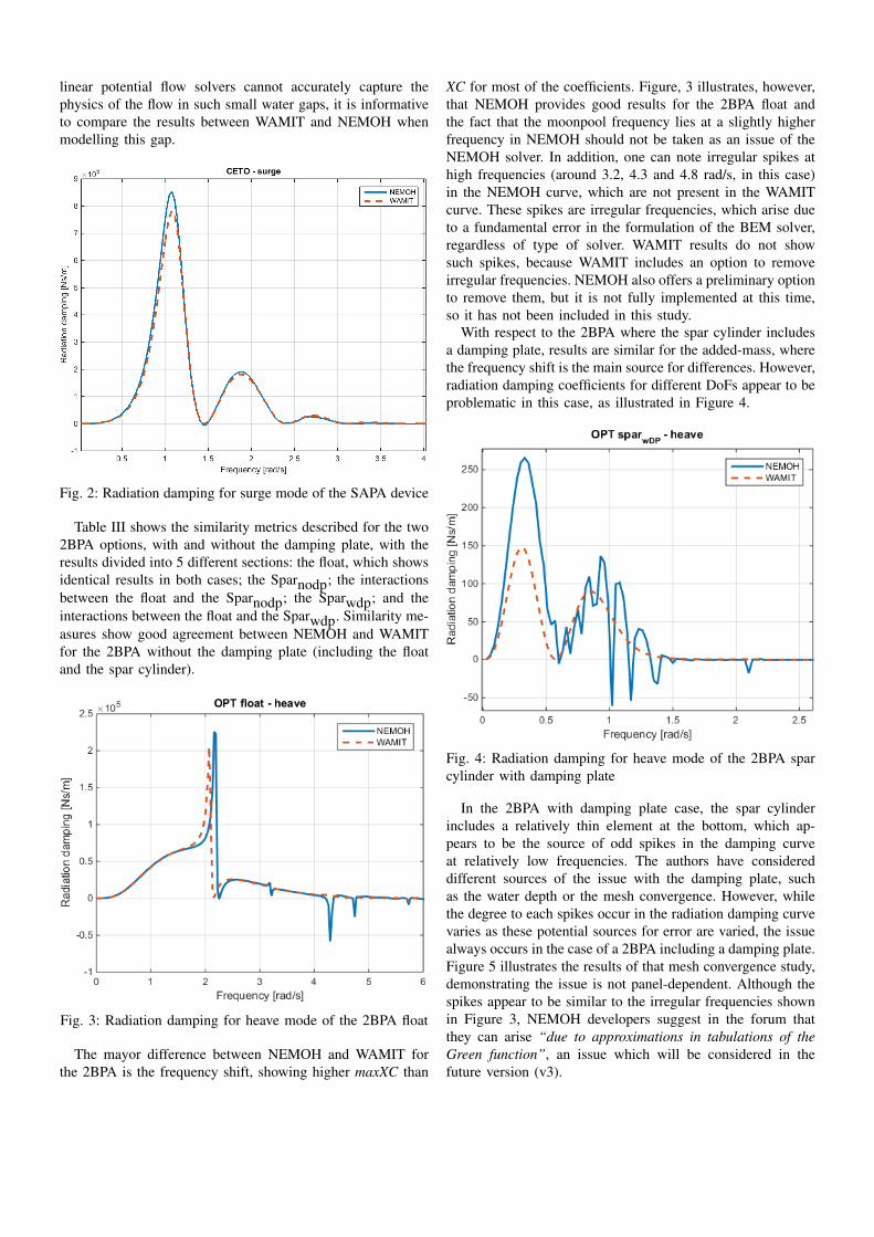
Results from the two solvers are so similar that the XC andmaxXC values are very close to 1, which would illustrate aperfect match, for all the DoFs. RMSr ratios also show valuesvery close to one and lower than 1 for most of the DoFs, whichmeans the amplitude for NEMOH is larger in general. Themain differences appear at the peaks of the coefficients, whereNEMOH coefficients are slightly larger. Results are almostidentical for the rest of the curve, as illustrated in Figure 2.
2) Two-body point absorber: The 2BPAs analysed here,which are similar to the Ocean Power Technology (OPT) [10]device, operate in deep water and consist of a torus float anda central spar cylinder with or without damping plate, anduse the same DoFs as the SAPA to extract energy from oceanwaves. The motivation for including a two-body system is toanalyse the capability of the BEM solvers to represent theinteraction between the two bodies. Further, the OPT deviceis of particular interest because of the damping plate of thecentral spar buoy, which may be an issue for NEMOH ifrepresented by thin elements. In addition, the presence ofthe moonpool between the float and the spar increases thecomplexity of the analysis. Although it is well known that
TABLE III: Comparison of the hydrodynamic coefficients obtained in WAMIT and NEMOH for the four device types.
∗ s, h and p refer to surge, heave and pitch modes, respectively, and s-p corresponds to the coupling between surge and pitch.∗∗ Results for the added-mass column in the case of the OWC free-surface modelled via the FC technique are obtained using the total inertia term that includes the added-mass and the
mass of the cylinder.∗∗∗N/A is used to show the corresponding measure is not applicable in that case.
linear potential flow solvers cannot accurately capture thephysics of the flow in such small water gaps, it is informativeto compare the results between WAMIT and NEMOH whenmodelling this gap.
Fig. 2: Radiation damping for surge mode of the SAPA device
Table III shows the similarity metrics described for the two2BPA options, with and without the damping plate, with theresults divided into 5 different sections: the float, which showsidentical results in both cases; the Sparnodp; the interactionsbetween the float and the Sparnodp; the Sparwdp; and theinteractions between the float and the Sparwdp. Similarity me-asures show good agreement between NEMOH and WAMITfor the 2BPA without the damping plate (including the floatand the spar cylinder).
Fig. 3: Radiation damping for heave mode of the 2BPA float
The mayor difference between NEMOH and WAMIT forthe 2BPA is the frequency shift, showing higher maxXC than
XC for most of the coefficients. Figure, 3 illustrates, however,that NEMOH provides good results for the 2BPA float andthe fact that the moonpool frequency lies at a slightly higherfrequency in NEMOH should not be taken as an issue of theNEMOH solver. In addition, one can note irregular spikes athigh frequencies (around 3.2, 4.3 and 4.8 rad/s, in this case)in the NEMOH curve, which are not present in the WAMITcurve. These spikes are irregular frequencies, which arise dueto a fundamental error in the formulation of the BEM solver,regardless of type of solver. WAMIT results do not showsuch spikes, because WAMIT includes an option to removeirregular frequencies. NEMOH also offers a preliminary optionto remove them, but it is not fully implemented at this time,so it has not been included in this study.
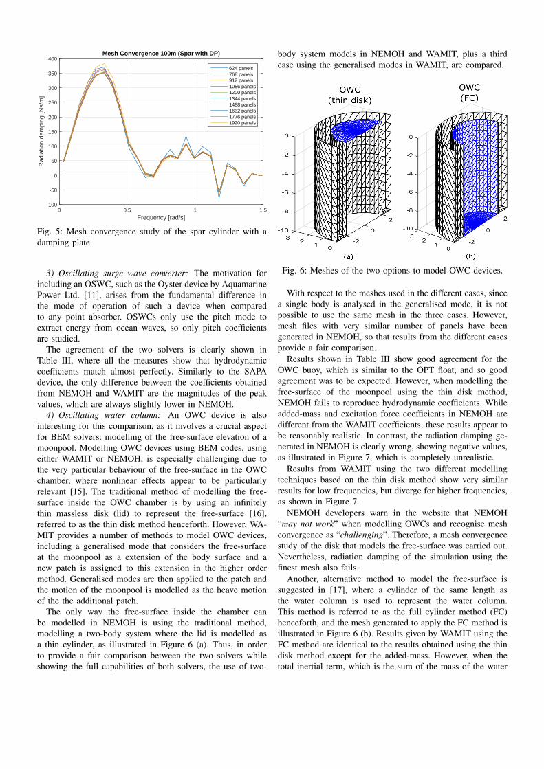
With respect to the 2BPA where the spar cylinder includesa damping plate, results are similar for the added-mass, wherethe frequency shift is the main source for differences. However,radiation damping coefficients for different DoFs appear to beproblematic in this case, as illustrated in Figure 4.
Fig. 4: Radiation damping for heave mode of the 2BPA sparcylinder with damping plate
In the 2BPA with damping plate case, the spar cylinderincludes a relatively thin element at the bottom, which ap-pears to be the source of odd spikes in the damping curveat relatively low frequencies. The authors have considereddifferent sources of the issue with the damping plate, suchas the water depth or the mesh convergence. However, whilethe degree to each spikes occur in the radiation damping curvevaries as these potential sources for error are varied, the issuealways occurs in the case of a 2BPA including a damping plate.Figure 5 illustrates the results of that mesh convergence study,demonstrating the issue is not panel-dependent. Although thespikes appear to be similar to the irregular frequencies shownin Figure 3, NEMOH developers suggest in the forum thatthey can arise “due to approximations in tabulations of theGreen function”, an issue which will be considered in thefuture version (v3).
Fig. 5: Mesh convergence study of the spar cylinder with adamping plate
3) Oscillating surge wave converter: The motivation forincluding an OSWC, such as the Oyster device by AquamarinePower Ltd. [11], arises from the fundamental difference inthe mode of operation of such a device when comparedto any point absorber. OSWCs only use the pitch mode toextract energy from ocean waves, so only pitch coefficientsare studied.
The agreement of the two solvers is clearly shown inTable III, where all the measures show that hydrodynamiccoefficients match almost perfectly. Similarly to the SAPAdevice, the only difference between the coefficients obtainedfrom NEMOH and WAMIT are the magnitudes of the peakvalues, which are always slightly lower in NEMOH.
4) Oscillating water column: An OWC device is alsointeresting for this comparison, as it involves a crucial aspectfor BEM solvers: modelling of the free-surface elevation of amoonpool. Modelling OWC devices using BEM codes, usingeither WAMIT or NEMOH, is especially challenging due tothe very particular behaviour of the free-surface in the OWCchamber, where nonlinear effects appear to be particularlyrelevant [15]. The traditional method of modelling the free-surface inside the OWC chamber is by using an infinitelythin massless disk (lid) to represent the free-surface [16],referred to as the thin disk method henceforth. However, WA-MIT provides a number of methods to model OWC devices,including a generalised mode that considers the free-surfaceat the moonpool as a extension of the body surface and anew patch is assigned to this extension in the higher ordermethod. Generalised modes are then applied to the patch andthe motion of the moonpool is modelled as the heave motionof the the additional patch.
The only way the free-surface inside the chamber canbe modelled in NEMOH is using the traditional method,modelling a two-body system where the lid is modelled asa thin cylinder, as illustrated in Figure 6 (a). Thus, in orderto provide a fair comparison between the two solvers whileshowing the full capabilities of both solvers, the use of two-
body system models in NEMOH and WAMIT, plus a thirdcase using the generalised modes in WAMIT, are compared.
Fig. 6: Meshes of the two options to model OWC devices.
With respect to the meshes used in the different cases, sincea single body is analysed in the generalised mode, it is notpossible to use the same mesh in the three cases. However,mesh files with very similar number of panels have beengenerated in NEMOH, so that results from the different casesprovide a fair comparison.
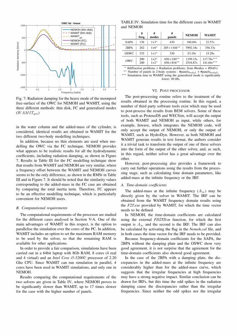
Results shown in Table III show good agreement for theOWC buoy, which is similar to the OPT float, and so goodagreement was to be expected. However, when modelling thefree-surface of the moonpool using the thin disk method,NEMOH fails to reproduce hydrodynamic coefficients. Whileadded-mass and excitation force coefficients in NEMOH aredifferent from the WAMIT coefficients, these results appear tobe reasonably realistic. In contrast, the radiation damping ge-nerated in NEMOH is clearly wrong, showing negative values,as illustrated in Figure 7, which is completely unrealistic.
Results from WAMIT using the two different modellingtechniques based on the thin disk method show very similarresults for low frequencies, but diverge for higher frequencies,as shown in Figure 7.
NEMOH developers warn in the website that NEMOH“may not work” when modelling OWCs and recognise meshconvergence as “challenging”. Therefore, a mesh convergencestudy of the disk that models the free-surface was carried out.Nevertheless, radiation damping of the simulation using thefinest mesh also fails.
Another, alternative method to model the free-surface issuggested in [17], where a cylinder of the same length asthe water column is used to represent the water column.This method is referred to as the full cylinder method (FC)henceforth, and the mesh generated to apply the FC method isillustrated in Figure 6 (b). Results given by WAMIT using theFC method are identical to the results obtained using the thindisk method except for the added-mass. However, when thetotal inertial term, which is the sum of the mass of the water
Frequency [rad/s]0 0.5 1 1.5 2 2.5 3 3.5 4
Rad
iatio
n da
mpi
ng [N
s/m
]
-1500
-1000
-500
0
500
1000OWC lid - heave
NEMOH (thin disk)WAMIT (thin disk)WAMIT
gm
NEMOH (FC)WAMIT (FC)
Fig. 7: Radiation damping for the heave mode of the moonpoolfree-surface of the OWC for NEMOH and WAMIT, using thethree different methods: thin disk, FC and generalised modes(WAMITgm)
in the water column and the added-mass of the cylinder, isconsidered, identical results are obtained in WAMIT for thetwo different two-body modelling techniques.
In addition, because no thin elements are used when mo-delling the OWC via the FC technique, NEMOH provideswhat appears to be realistic results for all the hydrodynamiccoefficients, including radiation damping, as shown in Figure7. Results in Table III for the FC modelling technique showthat results from WAMIT and NEMOH are very similar, wherea frequency offset between the WAMIT and NEMOH curvesseems to be the only difference, as shown in the RMSr in TableIII and in Figure 7. It should be noted that the similarity valuescorresponding to the added-mass in the FC case are obtainedby comparing the total inertia term. Therefore, FC appearsto be an effective modelling technique, which is particularlyconvenient for NEMOH users.
B. Computational requirements
The computational requirements of the processor are studiedfor the different cases analysed in Section V-A. One of themain advantages of WAMIT in this respect, is the option toparallelise the simulation over the cores of the PC. In addition,WAMIT includes an option to set the maximum RAM memoryto be used by the solver, so that the remaining RAM isavailable for other applications.
In order to provide a fair comparison, simulations have beencarried out in a 64bit laptop with 8Gb RAM, 8 cores (4 realand 4 virtual) and an Intel Core i5-5200U processor of 2.20Ghz CPU. Since WAMIT can run simulation in parallel, 4cores have been used in WAMIT simulations, and only one inNEMOH.
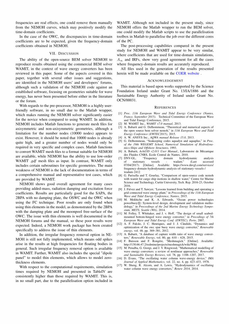
Results comparing the computational requirements of thetwo solvers are given in Table IV, where NEMOH proves tobe significantly slower than WAMIT, up to 17 times slowerfor the case with the higher number of panels.
TABLE IV: Simulation time for the different cases in WAMITand NEMOH
∗ #diffraction problems + #radiation problems, from #bodies + #DoFs)∗∗ Number of panels in 2-body systems : #panelsbody1 + #panelsbody2.
∗∗∗ Simulation time in WAMIT using the generalised mode is significantlylower: 49.48s.
VI. POST-PROCESSOR
The post-processing routine refers to the treatment of theresults obtained in the processing routine. In this regard, anumber of third party software tools exist which may be usedto post-process the results from BEM solvers. Some of thesetools, such as ProteusDS and WECSim, will accept the outputof both WAMIT and NEMOH as input, while others, forexample, Inwave, which integrates the NEMOH code, willonly accept the output of NEMOH, or only the output ofWAMIT, such as HydroDyn. However, as both NEMOH andWAMIT generate results in text format, the authors considerit a trivial task to transform the output of one of these solversinto the form of the output of the other solver, and, as such,in this regard, neither solver has a great advantage over theother.
However, post-processing also provides a framework tocarry out further operations using the results from the proces-sing stage, such as calculating time domain parameters, likeadded-mass at the infinite frequency or the IRF.
A. Time-domain coefficients
The added-mass at the infinite frequency (A∞) may bedirectly given by the solver in WAMIT. The IRF can beobtained from the WAMIT frequency domain results usingthe F2T.exe provided by WAMIT, for which the time vectorneeds to be defined.
In NEMOH, the time-domain coefficients are calculatedusing the external FD2TD.m function, for which the firstoutput is A∞ and the second is the IRF. The IRF can alsobe calculated by activating the flag in the Nemoh.cal file, andin both cases the time vector for the IRF needs to be provided.
Because frequency-domain coefficients for the SAPA, the2BPA without the damping plate and the OSWC show verygood agreement, it is not surprise that the agreement for thetime-domain coefficients also showed good agreement.
In the case of the 2BPA with a damping plate, the dis-crepancies in the added-mass at the infinite frequency areconsiderably higher than for the added-mass curve, whichsuggests that the irregular frequencies at high frequenciesmay have a strong negative impact. Similar conclusion can bedrawn for IRFs, but this time the odd spikes in the radiationdamping cause the discrepancies rather than the irregularfrequencies. Since neither the odd spikes nor the irregular
frequencies are real effects, one could remove them manuallyfrom the NEMOH curves, which may positively modify thetime-domain coefficients.
In the case of the OWC, the discrepancies in time-domaincoefficients are to be expected, given the frequency-domaincoefficients obtained in NEMOH.
VII. DISCUSSION
The ability of the open-source BEM solver NEMOH toreproduce results obtained using the commercial BEM solverWAMIT, in the context of wave energy converters has beenreviewed in this paper. Some of the aspects covered in thispaper, together with several other issues and suggestions,are identified in the NEMOH users’ and developers’ forums,although such a validation of the NEMOH code against anestablished software, focusing on geometries suitable for waveenergy, has never been presented before either in the literatureor the forum.
With regards to the pre-processor, NEMOH is a highly user-friendly software, in no small due to the Matlab wrapper,which makes running the NEMOH solver significantly easierfor the novice when compared to using WAMIT. In addition,NEMOH includes Matlab functions to generate mesh files foraxisymmetric and non-axisymmetric geometries, although alimitation for the number nodes (10000 nodes) appears toexist. However, it should be noted that 10000 nodes is alreadyquite high, and a greater number of nodes would only berequired in very specific and complex cases. Matlab functionsto convert WAMIT mesh files to a format suitable for NEMOHare available, while NEMOH has the ability to use low-orderWAMIT .gdf mesh files as input. In contrast, WAMIT onlyincludes certain subroutines for specific geometries. The mainweakness of NEMOH is the lack of documentation in terms ofa comprehensive manual and representative test cases, whichare provided by WAMIT.
NEMOH shows good overall agreement for many casesproviding added-mass, radiation damping and excitation forcecoefficients. Results are particularly good for the SAPA, the2BPA with no damping plate, the OSWC and the OWC whenusing the FC technique. Poor results are only found whenusing thin elements in the model, as demonstrated by the 2BPAwith the damping plate and the moonpool free-surface of theOWC. The issue with thin elements is well documented in theNEMOH forums and the manual, so these poor results wereexpected. Indeed, a NEMOH work package has been createdspecifically to address the issue of thin elements.
In addition, the irregular frequency removal option in NE-MOH is still not fully implemented, which means odd spikesarise in the results at high frequencies for floating bodies ingeneral. Such irregular frequency removal option is availablein WAMIT. Further, WAMIT also includes the special ”dipolepanel” to model thin elements, which allows to model zero-thickness elements.
With respect to the computational requirements, simulationtimes required by NEMOH and presented in TableIV areconsistently higher than those required by WAMIT. This is,in no small part, due to the parallelisation option included in
WAMIT. Although not included in the present study, sinceNEMOH offers the Matlab wrapper to run the BEM solver,one could modify the Matlab scripts to use the parallelisationtoolbox in Matlab to parallelise the job over the different coresof the PC.
The post-processing capabilities compared in the presentstudy for NEMOH and WAMIT appear to be very similar,where coefficients that are used for time-domain simulations,A∞ and IRFs, show very good agreement for all the caseswhere frequency-domain results are accurately reproduced.
All files used in the generation of the results presentedherein will be made available on the COER website .
ACKNOWLEDGEMENT
This material is based upon works supported by the ScienceFoundation Ireland under Grant No. 13/IA/1886 and theSustainable Energy Authority of Ireland under Grant No.OCN/00031.
REFERENCES
[1] Proc. 11th European Wave and Tidal Energy Conference (Nantes,France, September 2015). Technical Committee of the European Waveand Tidal Energy Conference, 2015.
[2] M. WAMIT Inc., WAMIT v7.0 manual, 2013.[3] A. Babarit and G. Delhommeau, “Theoretical and numerical aspects of
the open source bem solver nemoh,” in 11th European Wave and TidalEnergy Conference (EWTEC2015), 2015.
[4] A. W. ANSYS Inc., AQWA manual Release 15.0, 2013.[5] G. Delhommeau, “Seakeeping codes aquadyn and aquaplus,” in Proc.
of the 19th WEGEMT School, Numerical Simulation of Hydrodyna-mics:Ships and Offshore Structures, 1993.
[6] A. Babarit, Achil3D v2.011 User Manual., Laboratoire de Mecaniquedes Fluides CNRS, Ecole Central de Nantes, 2010.
[8] G. Parisella and T. Gourlay, “Comparison of open-source code nemohwith wamit for cargo ship motions in shallow water,” Centre for MarineScience and Technology, Curtin University, Tech. Rep. 2016-23, October2016.
[9] J. Fievez and T. Sawyer, “Lessons learned from building and operating agrid connected wave energy plant,” in Proceedings of the 11th EuropeanWave and Tidal Energy Conference, Nantes, 2015.
[11] M. Folley, T. Whittaker, and J. v. Hoff, “The design of small seabed-mounted bottom-hinged wave energy converter,” in Procedings of 7thEuropean Wave and Tidal Energy Conf. (EWTEC), Porto, 2007.
[12] A. F. Falcao, J. C. Henriques, and J. J. Candido, “Dynamics andoptimization of the owc spar buoy wave energy converter,” Renewableenergy, vol. 48, pp. 369–381, 2012.
[13] A. Babarit, “A database of capture width ratio of wave energy conver-ters,” Renewable Energy, vol. 80, pp. 610 – 628, 2015.
[14] F. Buisson and F. Rongere, “Meshmagick.” [Online]. Available:http://130.66.47.2/redmine/projects/meshmagick/wiki/Wiki
[15] M. Penalba, G. Giorgi, and J. V. Ringwood, “Mathematical modelling ofwave energy converters: a review of nonlinear approaches,” Renewableand Sustainable Energy Reviews, vol. 78, pp. 1188–1207, 2017.
[16] D. Evans, “The oscillating water column wave-energy device,” IMAJournal of Applied Mathematics, vol. 22, no. 4, pp. 423–433, 1978.
[17] W. Sheng, R. Alcorn, and A. Lewis, “Hydrodynamics of oscillatingwater column wave energy converters,” Renew 2014, 2014.