22
Using RAE Systems Colorimetric Gas Detection Tubes and Pumps

Using RAE Systems Colorimetric Gas Detection Tubes and Pumps
Important Cautions When Using Tubes
• Failure to wear protective equipment may lead to cuts and other severe injuries to eyes and hands
Wear safety glasses and gloves when opening or handling tubes with sharp edges
• Always test the pump for leaks immediately before using it for a series of measurements
Failure to test the pump for leakage may lead to dangerously inaccurate readings
Important Cautions When Using Tubes
• Avoid contact with tube contents in case of accidental breakage
Exposure to tube contents can result in significant health hazards
• Dispose of spent tubes according to local regulations
Review information listed in the Gas Detection Tube Data Sheet to identify materials that may require special disposal procedures.

The LP-1200 piston-type hand-pump description
• Draws fixed volume of gas, either 50 or 100 mL • Vacuum seal formed by a greased plunger gasket • Tapered inlet accommodates wide range of tubes • Inlet filter protects the shaft from particulates • Handle houses an end-of-flow indicator • Built-in counter keeps track of the number of strokes

RAE Colorimetric Tube Description and Packaging
• Each box contains 10 tubes • Instructions on back of box • Arrow indicates direction of insertion and airflow • Concentration scale and gas type printed on tube • Number of strokes, total sample volume and units of measure also
printed on tube
Tube Data Sheet Description
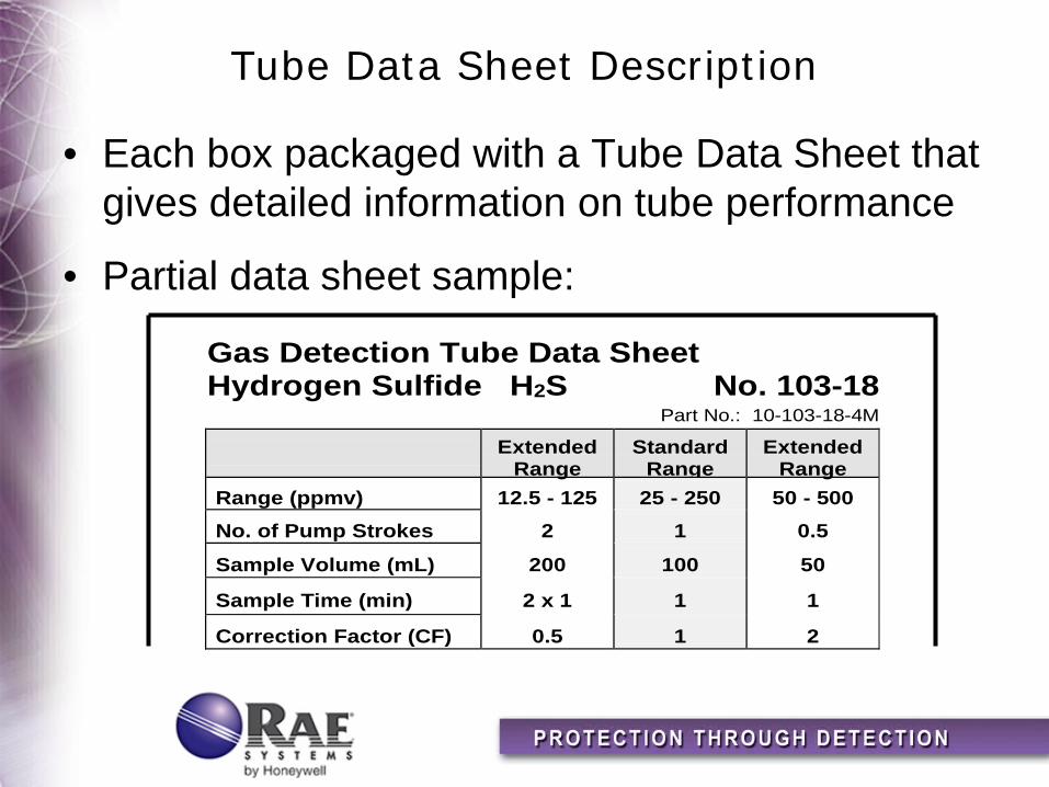
• Each box packaged with a Tube Data Sheet that gives detailed information on tube performance
• Partial data sheet sample:
Gas Detection Tube Data SheetHydrogen Sulfide H2S No. 103-18
Part No.: 10-103-18-4M
ExtendedRange
StandardRange
ExtendedRange
Range (ppmv) 12.5 - 125 25 - 250 50 - 500No. of Pump Strokes 2 1 0.5
Sample Volume (mL) 200 100 50
Sample Time (min) 2 x 1 1 1
Correction Factor (CF) 0.5 1 2
Testing the Hand-Pump for Leaks
• Insert unopened tube in hand-pump inlet • Pull one-full stroke on plunger • Wait two-minutes • While holding the pump and plunger, rotate the
plunger to release • Allow the plunger to be drawn gently back into
the pump shaft • The plunger should return to within three
millimeters of its original position
Measurement Procedure
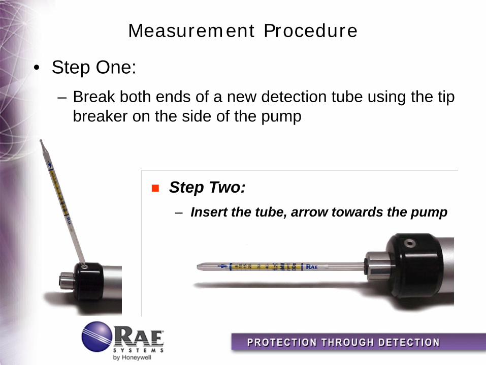
• Step One: – Break both ends of a new detection tube using the tip
breaker on the side of the pump
Step Two: – Insert the tube, arrow towards the pump
Measurement Procedure
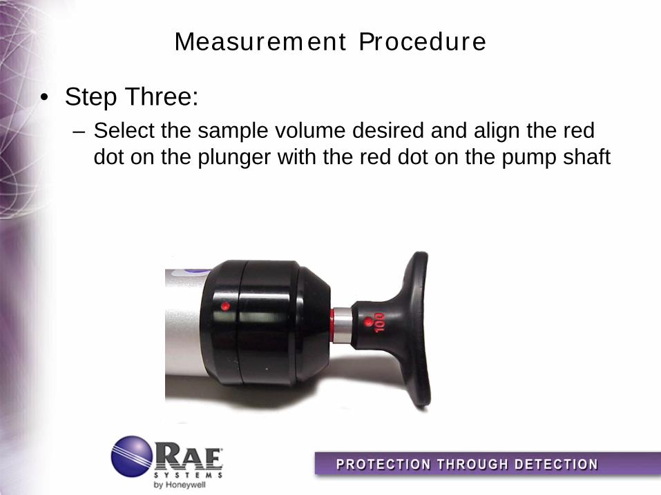
• Step Three: – Select the sample volume desired and align the red
dot on the plunger with the red dot on the pump shaft
Measurement Procedure
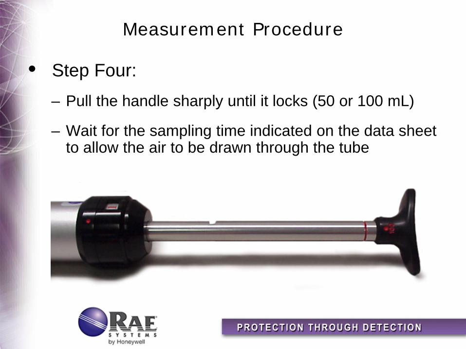
• Step Four: – Pull the handle sharply until it locks (50 or 100 mL)
– Wait for the sampling time indicated on the data sheet to allow the air to be drawn through the tube
Measurement Procedure
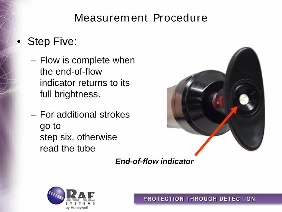
• Step Five:
– Flow is complete when the end-of-flow indicator returns to its full brightness.
– For additional strokes go to step six, otherwise read the tube
End-of-flow indicator
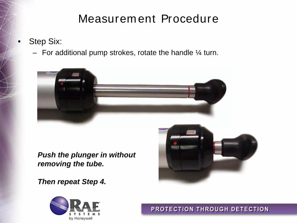
Measurement Procedure
• Step Six: – For additional pump strokes, rotate the handle ¼ turn.
Push the plunger in without removing the tube. Then repeat Step 4.
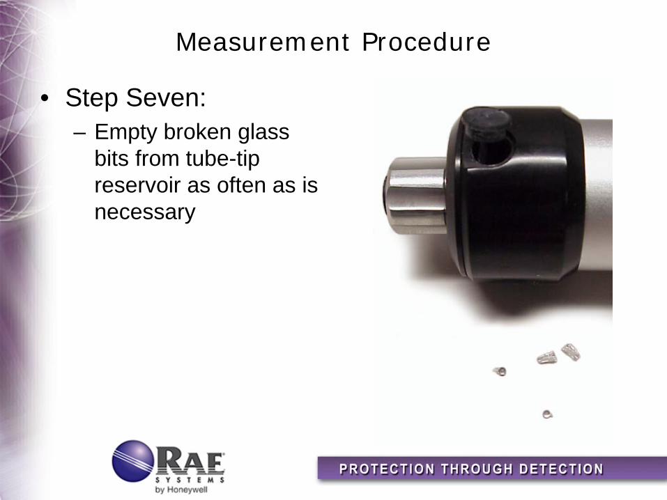
Measurement Procedure
• Step Seven: – Empty broken glass
bits from tube-tip reservoir as often as is necessary

Reading Tubes
• The reading is the furthest point along the color change
• If the leading edge is diagonal or diffuse, use the average of the minimum and maximum values
• The three tubes shown below are all read as 6.5%

Reading Tubes
• Read tube immediately after gas sampling, as colors may change, fade, or disperse with time
• If a non-standard number of pump strokes was used for sampling, multiply the reading by the correction factor given on the Tube Data Sheet
• If humidity and temperature corrections are necessary as indicated on the Data Sheets, multiply the observed readings by the given correction factor(s) (CF) to obtain the true concentration

Sampling Volumes and Ranges
• Standard Sampling Volume and Ranges – Standard stroke requirements are printed on each
tube – Gas concentrations can be measured by the scale
printed on the tube
• Extended Sampling Volumes and Ranges – Varying the number of strokes (volume) allows
measurement of lower and higher concentrations than printed
– Varying the stroke means that the printed scale reading must be multiplied by a correction factor (CF)

Cross-Sensitivity Cautions
• Colorimetric tubes are, by nature, selective;
• However, some compounds interfere with certain measurements
– Each Tube Data Sheet lists possible interfering compounds, but others may also exist
– Interfering compounds can increase or decrease the reading
– Be aware of potential interferences!

Maintenance of the LP-1200 Piston Hand Pump
• Tube Tip Reservoir
– Remove the tube tip reservoir cover as needed to empty the broken glass reservoir that is in the pump end fitting
Tube-tip reservoir cover
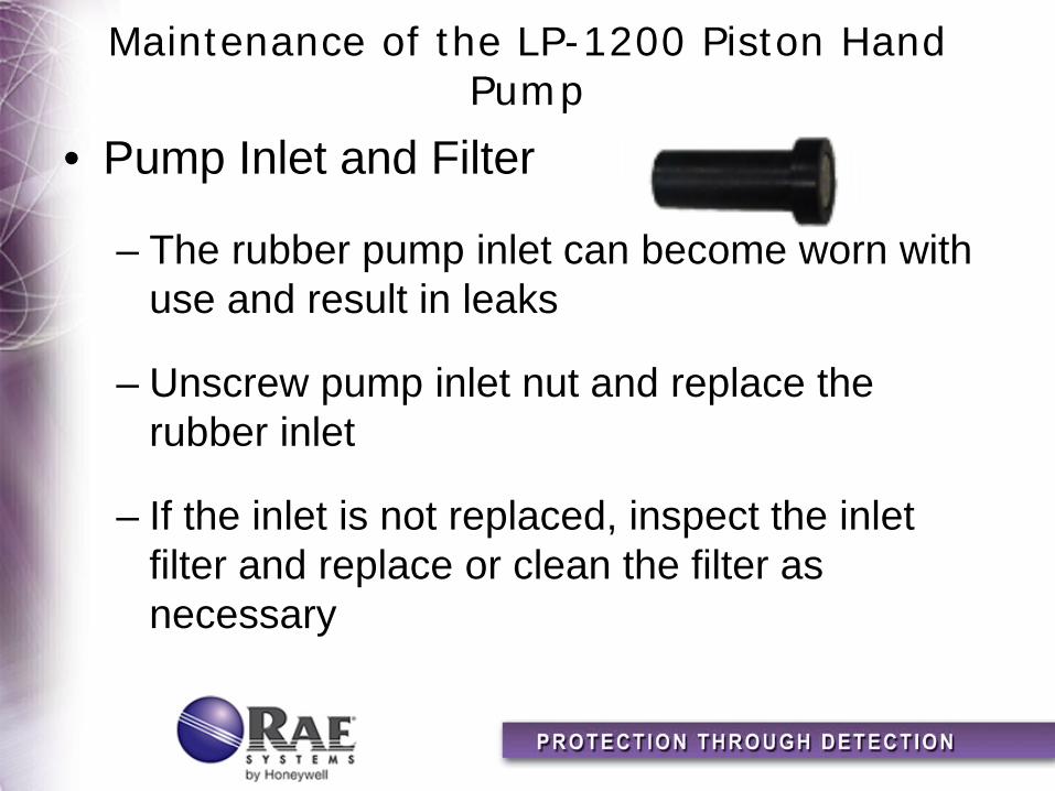
Maintenance of the LP-1200 Piston Hand Pump
• Pump Inlet and Filter
– The rubber pump inlet can become worn with use and result in leaks
– Unscrew pump inlet nut and replace the rubber inlet
– If the inlet is not replaced, inspect the inlet filter and replace or clean the filter as necessary
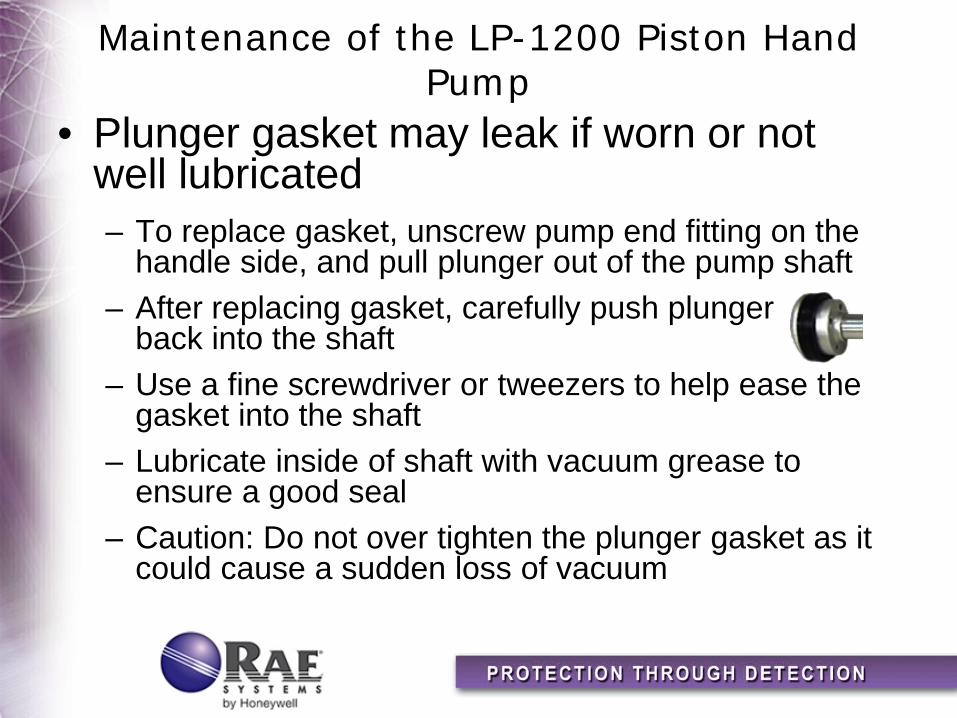
Maintenance of the LP-1200 Piston Hand Pump
• Plunger gasket may leak if worn or not well lubricated – To replace gasket, unscrew pump end fitting on the
handle side, and pull plunger out of the pump shaft – After replacing gasket, carefully push plunger
back into the shaft – Use a fine screwdriver or tweezers to help ease the
gasket into the shaft – Lubricate inside of shaft with vacuum grease to
ensure a good seal – Caution: Do not over tighten the plunger gasket as it
could cause a sudden loss of vacuum
Maintenance of the LP-1200 Piston Hand Pump
• Inlet Valve
– Inlet check-valve may cause leaks if worn or not lubricated
– Unscrew the end-fitting on the inlet side, and pull out the disk-shaped rubber-inlet check-valve
– Replace as necessary, adding a light coat of grease around the hole
Maintenance of the LP-1200 Piston Hand Pump
• Outlet Valve
– Replace outlet check-valve gasket if there is resistance on the return stroke
– Using the special tool or needle-nose pliers, unscrew the plunger tip from the plunger rod
– Replace O-ring and check-valve gasket as necessary, and reassemble
– Inspect gasket-ring in the inlet end-fitting, and replace if damaged before screwing the end-fitting back on


