ABSTRACTThe aim of this paper is to spread the use of Rapid Prototyping technology (RP) into architecture. Rapid Prototyping is being used since its origin by designers in different fields as product design, automobile industry, medical applications, arts, and it has been proved that it is an essential tool in any design process. The designer has the possibility of building the scale model in very few hours directly from the CAD system. He can touch the scale model to verify if its shape is the desired one, and use it as reference if any modification is needed during the design process. A methodology of work has been defined, in which has been described the use of three-dimensional CAD software in the design stage. As case study, some models have been built to illustrate the effectiveness of this technology in the creation of scale models with free-form shapes and complex surfaces.
1. INTRODUCTIONRapid prototyping (RP) has become one of the fastest growing new technologies since its introduction in 1986. By means of this technology it is possible to build prototypes and touch them in just a few hours, from a CAD file in which the geometry of the model is defined in 3D. These prototypes are used to visualize those complex shapes not easily seen or understood on conventional drawings. It gives to the designer the possibility of verifying the shape of the product, validate if it fits into the assembly, or if it complies with the desired function. Rapid prototyping is a valuable tool for the designer, and it cuts down the required time to design a product.
This technology was conceived as an industrial application to speed up the design and manufacturing processes. But having in your hands a 3D touchable model of what you want to or even wish to build is something that can be useful in lot of fields. It has been used in medical application, arts (sculpture, jewelry…), archaeology; and it is a potential tool for the architectural field.A brief approach to this technology and the way it works is shown in the next section. It just tries to show what we are going to deal with, and a range of the most common available techniques with some description of their functionalityand specifications.The next section is referred to the use of this technology into architecture and how can be useful in this field.In the next point, the design process methodology is described. It tries to be a guide of the logical procedure to introduce RP into an architectural design process and to take the maximum benefit from it.Finally, the case studies illustrate the benefits of this technology applied to the architecture field. Eden330 from Objet Technologies Inc. (see Figure 1) has been used to build all the physical models described in that section and along the paper. It combines speed with accuracy, nice surface finish and medium cost.
2. RAPID PROTOTYPING TECHNOLOGIESThinking of this term would lead us to its right meaning: Rapid Prototyping (RP) is a technology used to build physical prototypes in a really quick way. Quick or rapid manufacture is a relative expression, and it is referred to conventional manufacturing processes such as milling or turning. To explain this expression let’s say that to obtain a model of 300x300x300 mm. would be a matter of hours. RP, also called free form fabrication technology, enables the creation of three dimensional (3D) prototypes in an earlier and less expensively way than was possible before.RP is the term used to refer to a group of technologies which are conceived to produce physical models directly from 3D computer data. Normally, it is used to validate a design, allowing the visualization of a product at any stage of the process, from its conceptual design to the creation of every single detail. This would allow the designer to make changes on the model at very early stages of the design process. These technologies differ between them, but all of them build directly physical models by adding thin layers of material, until the model is completed. Those layers are obtained by dividing a 3D Cad model into parallel slices.
Figure 1. Objet Eden 330 Head Unit
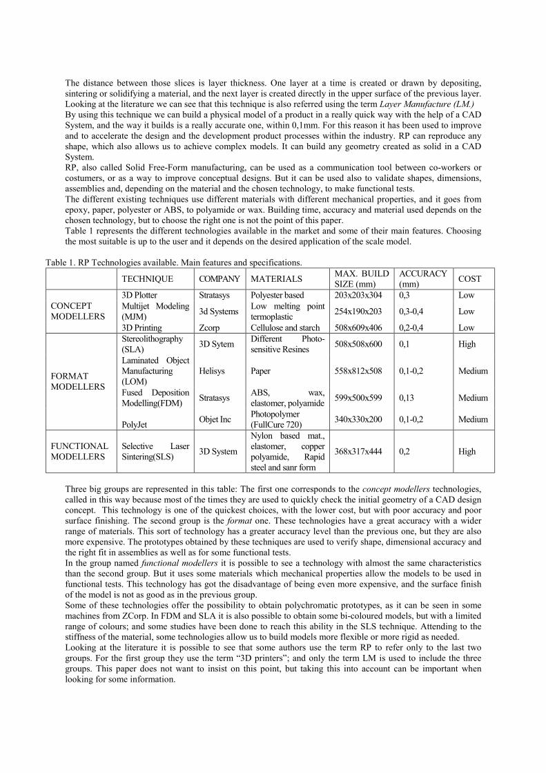
The distance between those slices is layer thickness. One layer at a time is created or drawn by depositing, sintering or solidifying a material, and the next layer is created directly in the upper surface of the previous layer. Looking at the literature we can see that this technique is also referred using the term Layer Manufacture (LM.) By using this technique we can build a physical model of a product in a really quick way with the help of a CAD System, and the way it builds is a really accurate one, within 0,1mm. For this reason it has been used to improve and to accelerate the design and the development product processes within the industry. RP can reproduce any shape, which also allows us to achieve complex models. It can build any geometry created as solid in a CAD System. RP, also called Solid Free-Form manufacturing, can be used as a communication tool between co-workers or costumers, or as a way to improve conceptual designs. But it can be used also to validate shapes, dimensions, assemblies and, depending on the material and the chosen technology, to make functional tests.The different existing techniques use different materials with different mechanical properties, and it goes from epoxy, paper, polyester or ABS, to polyamide or wax. Building time, accuracy and material used depends on the chosen technology, but to choose the right one is not the point of this paper. Table 1 represents the different technologies available in the market and some of their main features. Choosing the most suitable is up to the user and it depends on the desired application of the scale model.
Table 1. RP Technologies available. Main features and specifications.
TECHNIQUE COMPANY MATERIALS MAX. BUILD SIZE (mm)
ACCURACY(mm) COST
3D Plotter Stratasys Polyester based 203x203x304 0,3 LowMultijet Modeling (MJM) 3d Systems Low melting point
PolyJet Objet Inc Photopolymer (FullCure 720) 340x330x200 0,1-0,2 Medium
FUNCTIONAL MODELLERS
Selective Laser Sintering(SLS) 3D System
Nylon based mat., elastomer, copper polyamide, Rapid steel and sanr form
368x317x444 0,2 High
Three big groups are represented in this table: The first one corresponds to the concept modellers technologies, called in this way because most of the times they are used to quickly check the initial geometry of a CAD design concept. This technology is one of the quickest choices, with the lower cost, but with poor accuracy and poor surface finishing. The second group is the format one. These technologies have a great accuracy with a wider range of materials. This sort of technology has a greater accuracy level than the previous one, but they are also more expensive. The prototypes obtained by these techniques are used to verify shape, dimensional accuracy and the right fit in assemblies as well as for some functional tests.In the group named functional modellers it is possible to see a technology with almost the same characteristics than the second group. But it uses some materials which mechanical properties allow the models to be used in functional tests. This technology has got the disadvantage of being even more expensive, and the surface finishof the model is not as good as in the previous group.Some of these technologies offer the possibility to obtain polychromatic prototypes, as it can be seen in some machines from ZCorp. In FDM and SLA it is also possible to obtain some bi-coloured models, but with a limited range of colours; and some studies have been done to reach this ability in the SLS technique. Attending to the stiffness of the material, some technologies allow us to build models more flexible or more rigid as needed.Looking at the literature it is possible to see that some authors use the term RP to refer only to the last two groups. For the first group they use the term “3D printers”; and only the term LM is used to include the three groups. This paper does not want to insist on this point, but taking this into account can be important when looking for some information.
3. RAPID PROTOTYPING AND ARCHITECTURERapid Prototyping technology is used along different fields, like product design, automobile industry, medical applications, architecture, art (see Figure 2), to build prototypes directly from CAD models. Although these fields seem to be quite different, all of them have something in common. There is a design process in which the shape of the component is defined, according to some specifications and constraints. Although the existing design tools (CAD and Computer Aided Engineering-CAE) seem to be enough to complete the design process, it is still necessary to build the model, to verify its shape, fit and functionality, in order to use it as feedback for the design process until the desired shape is achieved.
The use of RP in architecture is described by some other authors [1-4]. Many types of scale models can be used in architecture. Sometimes a conceptual model without many details is enough to show the general shape of the building and the surroundings (see figure 3a,3b), and in other cases a specific constructive detail is needed (see figure 3c,3d). In both cases, we are always thinking in scale models used by the architect in the design stage, and not in those final models used to show to the public or to the customer. The architect uses these scale models asfeedback for the design process and to make the needed modifications until the final shape is achieved. This information is essential for the designer at this stage.
(a) (b) (c) (d)Figure 3.- Types of scale models. (a,b) Conceptual models. E 1:1000 (c,d) Detailed models. E 1:75
We can make an analogy between the Rapid Prototyping and the 2D plotting systems. About fifteen years ago, a designer working with CAD tools had to plot the drawings from CAD 2D, and then he could decide if any modification was needed. Nowadays, Rapid Prototyping allows the designer to build the model from CAD 3D, to validate its shape. In both cases, the physical model (paper or solid) is giving a valuable extra information to the designer, that is not shown in the screen. Although the designer has been working and manipulating for hours and days the 3D model in the screen, the perception of the volume and the proportions of the model are totally different when the designer touches the scale model. A quick look to the scale model is enough to perceive if the model is valid or not.With the introduction of computers and CAD tools, there has been a clear evolution in the architecture design process. Not many years ago, the conception and the definition of the projects were made by hand using drawing boards. It was replaced by CAD tools in which the designers define the models in 2D. In the last years, 3D CAD models are also being used together with 2D CAD models to complete them, although it is being introduced slowly, as it requires skilled users to manage the available software. Nowadays, although the initial sketches are made by hand, the project is always completed using CAD.Those models built using RP need to be modelled as solids, using 3D CAD tools. Some commercial CAD 3D software (Catia, ProEngineer, Unigraphics, SolidWorks) conceived for industrial purposes are starting to be used in the architecture field. These sorts of tools offer the designer a new way to generate complex shapes, but the user needs to be skilled enough to manage these tools. It is quite common to find models in which the user has not been able to achieve the desired shape because the designer does not know all the functionalities offered by the software. In these cases the shape of the model is simplified by the designer, according to his skills using the software. So, the final shape of the model is given by the software and not by the designer, total disaster.
Figure 4a shows an example of a scale model of a tensile membrane structure, generated in Rapid Prototyping. The width of the membrane is only 0.4 mm. The next example (Figure 4b) shows a surface, which consist of four separated panels, built independently and then assembled. It can be seen the continuity of the total surface in terms of position, tangency and curvature. Figure 4c shows a detail model of a handrail.
(a) (b) (c)Figure 4. Complex shapes. (a) Tensile membrane E 1:1000 (b) Surface panel. E 1:75 (b) Handrail. E 1:100
Traditional ways for creating architecture scale models are compared with the RP technology, in terms of accuracy, cost, time to complete a model, or other parameters. In some cases, RP is more suitable and in other cases, traditional methods are more adequate. So, the designer should have enough criteria to decide which method is more appropriate depending on the model to be built.Using Rapid Prototyping, accuracy and repeatability can be assured, details, and the time required for building complex shapes is clearly reduced. Using traditional methods the quality and the cost of the model depends on the ability of the model maker. By means of Rapid Prototyping technology, complex shapes and surfaces can be built, directly from CAD models.Figure 5a shows a scale model of a tubular structure. Each bar has been built separately and then assembled. In the figures 5b and 5c, it can be seen the possibility of building different textures that can be used for walls, floors or covers. Figure 5d shows another detail of the Handrail.
(a) (b) (c) (d)Figure 5. Scale models. (a) Tubular Structure E 1:1000. (b)(c) Tectures. E 1:75 (b) Handrail. E 1:50
As described before, RP can also be used in Sculpture, to built physical models. Figure 6a shows a sculpture designed by Gerardo Armesto Larzabal, located in Vitoria, Spain. It is made of Stainless Steel and it is sixmeters tall. Figure 6b shows the 3D solid, modelled in Autocad and used to design and built the Sculpture. Figure 6c shows a RP model built (E 1:100)
(a) (b) (c)Figure 6. “Science Tree”.Sculpture designed by Gerardo Armesto Larzabal. University Campus, Vitoria, Spain.
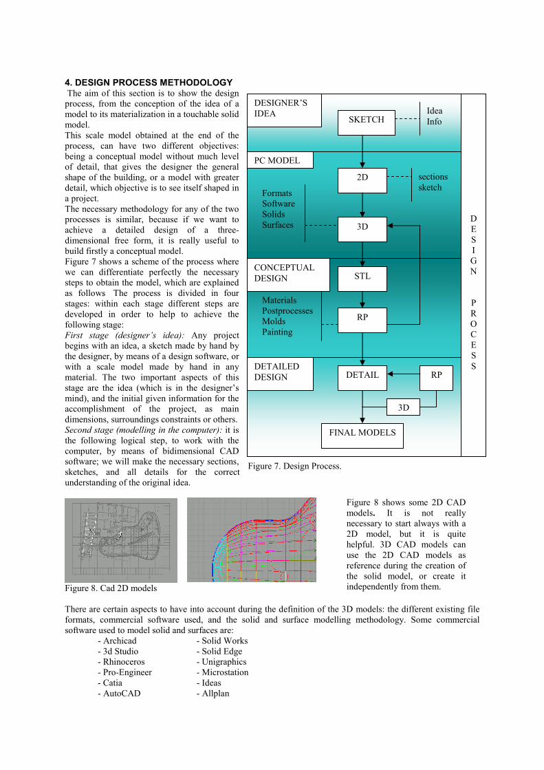
4. DESIGN PROCESS METHODOLOGYThe aim of this section is to show the design process, from the conception of the idea of amodel to its materialization in a touchable solidmodel. This scale model obtained at the end of the process, can have two different objectives: being a conceptual model without much level of detail, that gives the designer the general shape of the building, or a model with greater detail, which objective is to see itself shaped in a project. The necessary methodology for any of the two processes is similar, because if we want to achieve a detailed design of a three-dimensional free form, it is really useful to build firstly a conceptual model.Figure 7 shows a scheme of the process where we can differentiate perfectly the necessary steps to obtain the model, which are explained as follows. The process is divided in four stages: within each stage different steps are developed in order to help to achieve the following stage:First stage (designer’s idea): Any project begins with an idea, a sketch made by hand by the designer, by means of a design software, or with a scale model made by hand in any material. The two important aspects of this stage are the idea (which is in the designer’s mind), and the initial given information for the accomplishment of the project, as main dimensions, surroundings constraints or others.Second stage (modelling in the computer): it is the following logical step, to work with the computer, by means of bidimensional CAD software; we will make the necessary sections, sketches, and all details for the correct understanding of the original idea.
Figure 8. Cad 2D models
There are certain aspects to have into account during the definition of the 3D models: the different existing file formats, commercial software used, and the solid and surface modelling methodology. Some commercial software used to model solid and surfaces are:
Figure 8 shows some 2D CAD models. It is not really necessary to start always with a 2D model, but it is quite helpful. 3D CAD models can use the 2D CAD models as reference during the creation of the solid model, or create itindependently from them.
Figure 7. Design Process.
On the other hand it is important to know the compatibility between the software used. There are some neutral formats like IGES, STEP or DXF used as standards, which allow the user to change information between different applications. In some cases, some information can be lost during the conversion, as each software usesits own data format to store and represent the geometry. In some occasion, 3D CAD software is used to generate complex surfaces, but is not appropriate for solid modelling. It is important to know that the 3D model needs to be a 3D solid to built it using rapid prototyping. An alternative would be to use one software to model the surfaces and another one to build the solid. The surfaces generated on the first model will be used as references during the creation of the solid model.Third stage (conceptual design): Once the 3D solid model is completed, it should be saved in STL format (it stands from STeroLitography). This file will generate a facet model (the facets can be controlled by the different software, controlling therefore the final resolution of the model) and finally the model is sent to be built. Most of the software can export the model to this format.A touchtable model on the designer’s hand helps the designer to see if the final model is what he shaped in his mind. He can go back to the 3D model, in order to make the necessary changes on the computer model if needed, until the desired model is achieved.We can apply several postprocesses to the model we obtain from rapid prototyping. Some are described:Silicone molds: vacuum casting system can be used to generate a silicone mold from the original RP model. Small series can be built using this mold, and materials with different mechanical properties, colours or transparencies can be used.Painting: the rapid prototyping model can be painted if we want to apply a different outer aspect.Sand blasting: it is a technique that applied to the model obtains different surface finishing and a different outer aspect.Fourth stage (detailed design): In this phase we look for the piece obtained through rapid prototyping, looking if it has the required detail level. At this point it is possible to achieve directly the correct three-dimensional model or by successive approaches building intermediate models with rapid prototyping, until we obtain the desired final model.
5. CASE STUDIES
Kunsthaus Graz, AustriaWith the first case study we want to show the potential of rapid prototyping machines at the time of making a detailed structure building scale model. We chose to start with an existing building, which would have a complex form. The aim was to build a scale model, not easy to make with traditional techniques because of its complexity. As well, the building must have different singular elements that contribute to have greater complexity.The chosen building is the Kunsthaus Graz(see Figure 10), designed by the architect Peter Cook. In this point we want to thank to Manfred Grohmann (Bollinger und Grohmann GmbH, Germany) for the building documentation we have used, whose help has been essential to complete this case study.The Kunsthaus Graz volume has a really complex free form, hardly to be modelled, which has the extra difficulty of being covered by Plexiglas panels, each one of them
Figure 9. 3D Solid Model
Figure 10. Kunsthaus Graz, Austria
different from the others, a very complicated work to make in a scale model with others technologies that are not based on rapid prototyping. The case study is going to be fitted to the methodology previously explained on point 4.First stage, conceptual idea stage: This stage is already done by the architect. There is a work made by the people who are going to build the scale model of learning the complexity of the building and studying the different ways to build the scale model. Other decisions can be taken, like 3D software used. Second Stage: The given documentation was a computer model of three-dimensional positioning of the Plexiglas panels, a structure model, and 2D planes with the detailed situation of the building (courtesy of Manfred Grohmann). A three dimensional model needs to be created from the given information. This is the most important stage of the work, because this model will be used as reference for the next stages. It must be done on a standard format, in order to work with any 3D software. The original model was the Plexiglas panels localization (see Figure 11), which was modelled in Rhino, and will be used as initial reference. From this model, a collection of points and curves will be generated as the skeleton of the model, and then will be exportedit to IGES format, to be used later with Catia and ProEngineer.
Figure 11. Original model, point model, structure detail model.
Catia v5 was used to work with this initial skeleton made of curves and points , introducing us in the next stage, (see Figure 12), in which the surfaces and the main solid is created. A scale model is built in RP, and with this conceptual scale model we can see the main volume of the building and its final aspect. In the conceptual scale model we can take several decisions for the detailed model. Although the model is a solid generated on Catia v5, ProEngineer has been used to create the STL file, with greater definition, which will be used to build the model in the RP machine.
Figure 12. Conceptual design model. (Catia v5)
Once the main volume is built and its shape has been validated, we start with the definition of the model details, as the panels distribution or local shapes (see Figure 13). Several scale models are built again, and different post processes like sand blasting or painting are applied, to verify the final aspect of the future scale model, to see how it looks like, and finally, we go back to the three dimensional software (Catia v5), to apply the different changes, create the new STL file and start building the final detailed model.
Figure 13. Study of a singular form(nozzles ), STL files ready to print, final detailed model part.
Alfafar Auditorium, Valencia, SpainIn the next case study, the building is still in its design stage. The project has been prepared for the Architecture Competition of the Alfafar Auditorium and Cultural Center, located in Valencia, Spain. The competition was held in May 2005 and the architects Pedro Elcuaz and Eduardo Arilla are the authors of the project.As in the previous case study, the shape of this building has been created using a 3D CAD software to model the different surfaces, and how are they interconnected. Figure 14 shows some views of the model, which has been completed using Rhino. Once the surface model is finished, it needs to be solidified, in order to generate the STL file, which will be used to build the scale model by the RP system.
Figure 14. Rhino views of the proposed Alfafar Auditorium and Cultural Center by Pedro Elcuaz and Eduardo Arilla
The scale model has been built in two different scales (E 1:2000 and E 1:600). Figure 15 shows different details of the scale model built using RP. The time needed to complete the E 1:600 scale model has been 6 hours, being its size 230x115x33 mm and its weight about 230 grams. The time required to build the small model (1:2000) was only 53 minutes. Its size is 71x36x10mm and its weight is about 10 grams.
(a) (b) (c) (d) (e)Figure 15. Scale model details of the Auditorium and Cultural Center. (a) E 1:2000 model. (b,c,d,e) E 1:600 model
6.- CONCLUSIONSThe use of Rapid Prototyping technologies is essential in any design fields. Although it was conceived as an industrial application, the architectural field can also take benefit from this technology. It gives the architect the possibility to visualize those complex shapes not easily seen or understood on conventional drawings, and touch them to verify the shape. It can be used in early design stages to build a conceptual model or in later stages when details are needed.Complex shapes can be obtained using surface and solid modeling CAD software, and then build the physical model. In a few hours the model can be built easily, in a similar way as a 2D drawing is plotted.In a short time, Rapid Prototyping will become a technology that will be used routinely by many architects in conjunction with the traditional existing ways of creating scale models.
REFERENCES[1] J.Giannatsis, V.Dedoussis, D. Karalekas, Architectural scale modelling using stereolithography, Rapid Prototyping Journal, 2002, volume8, number 3 , p.200-207.
[2] I.Gibson, T.Kvan, L.W.Ming, Rapid prototyping for architectural models, Rapid Prototyping Journal, 2002, volume8, number 2, p.91-99.
[3] G.Ryder et al, Rapid design and manufacture tools in architecture, Automation in Construction, 2002, volume 11, p.279 -290.
[4] Andreas Gebhardt, Rapid Prototyping, Carl Hanser Verlag, Munich 2003, ISBN 1-56990-281-X, 379 pp.