Using Telelogic DOORS and Microsoft Visio to Model and Visualize Complex Business Processes “The Business Driven Application Lifecycle” Bob Sherman Procter & Gamble Pharmaceuticals [email protected]Michael Sutherland Galactic Solutions Group, LLC [email protected]Prepared for the Telelogic 2005 User Group Conference, Americas & Asia/Pacific http://www.telelogic.com/news/usergroup/us2005/index.cfm 24 October 2005 Abstract: The fact that most Information Technology (IT) projects fail as a result of requirements management problems is common knowledge. What is not commonly recognized is that the widely haled “use case” and Object Oriented Analysis and Design (OOAD) phenomenon have resulted in little (if any) abatement of IT project failures. In fact, ten years after the advent of these methods, every major IT industry research group remains aligned on the fact that these projects are still failing at an alarming rate (less than a 30% success rate). Ironically, the popularity of use case and OOAD (e.g. UML) methods may be doing more harm than good by diverting our attention away from addressing the real root cause of IT project failures (when you have a new hammer, everything looks like a nail). This paper asserts that, the real root cause of IT project failures centers around the failure to map requirements to an accurate, precise, comprehensive, optimized business model. This argument will be supported by a using a brief recap of the history of use case and OOAD methods to identify differences between the problems these methods were intended to address and the challenges of today’s IT projects. A new framework, dubbed the Business Driven Application Lifecycle (BDAL), will be offered as a method for addressing the real root causes of IT project failures. The reader will learn how the framework addresses the business modeling and analysis needs of today’s IT projects in a way that supports a rigorous mapping of related information system’s requirements to affected components of the business model. A DOORS/VISIO based approach for implementing the BDAL framework and managing related graphical renderings of that framework will be reviewed. Lastly, a new integration between VISIO and DOORS will be reviewed to address synchronization issues that arise from using both DOORS and VISIO to implement a business modeling framework.
Abstract: The fact that most Information Technology (IT) projects fail as a result of requirements management problems is common knowledge. What is not commonly recognized is that the widely haled “use case” and Object Oriented Analysis and Design (OOAD) phenomenon have resulted in little (if any) abatement of IT project failures. In fact, ten years after the advent of these methods, every major IT industry research group remains aligned on the fact that these projects are still failing at an alarming rate (less than a 30% success rate). Ironically, the popularity of use case and OOAD (e.g. UML) methods may be doing more harm than good by diverting our attention away from addressing the real root cause of IT project failures (when you have a new hammer, everything looks like a nail).
This paper asserts that, the real root cause of IT project failures centers around the failure to map requirements to an accurate, precise, comprehensive, optimized business model. This argument will be supported by a using a brief recap of the history of use case and OOAD methods to identify differences between the problems these methods were intended to address and the challenges of today’s IT projects.
A new framework, dubbed the Business Driven Application Lifecycle (BDAL), will be offered as a method for addressing the real root causes of IT project failures. The reader will learn how the framework addresses the business modeling and analysis needs of today’s IT projects in a way that supports a rigorous mapping of related information system’s requirements to affected components of the business model. A DOORS/VISIO based approach for implementing the BDAL framework and managing related graphical renderings of that framework will be reviewed. Lastly, a new integration between VISIO and DOORS will be reviewed to address synchronization issues that arise from using both DOORS and VISIO to implement a business modeling framework.
Telelogic 2005 User Group Conference, Americas & Asia/Pacific Using Telelogic DOORS and Microsoft Visio to Model and Visualize Complex Business Processes – v1.0
Author Biography - Bob Sherman: Bob Sherman graduated in 1985 from the University of South Florida with a double major in Chemistry and Chemical Engineering (specializing in Controls Engineering). Bob has spent 15 years in Procter & Gamble's engineering organization (starting in 1985), and has gained valuable experience in proper requirements management working on new product initiatives in nearly every P&G product/business area. Bob's five years in P&G's IT organization has provided has provided him the opportunity to merge the best of Engineering and IT business process modeling and requirements management methods. The management of software development and continual improvement of such methods has been a central theme of Bob's 20 year career. Bob is currently with Procter & Gamble Pharmaceuticals. Author Biography - Michael Sutherland: Michael Sutherland is the founder of Galactic Solutions Group and has 15 years experience working with automotive and military suppliers and manufacturers. He is currently working with General Dynamics Land Systems on the Future Combat Systems Manned Ground Vehicles project, developing and deploying systems engineering processes and tools. Michael has a master's degree in electrical and computer engineering from Oakland University in Rochester, MI. He also specializes in the application of the DOORS Enterprise Requirements Suite, mentoring and teaching application, customization (DXL) and information modeling to a wide variety of clients across the United States.
Telelogic 2005 User Group Conference, Americas & Asia/Pacific Using Telelogic DOORS and Microsoft Visio to Model and Visualize Complex Business Processes – v1.0
In 1992, the IT world was introduced to “use cases” by Ivar Jacobson and his team at Ericsson. This simple method of requirements elucidation has been successfully employed in the development of countless consumer electronics (e.g. microwaves, CD players, cell phones) and desktop software application products (e.g. spreadsheets, email clients, web browsers). For these projects, success depended only upon understanding the requirements of the interaction between the user and the new product (hereinafter “usage scenarios”). The usage scenarios for each product were few in number, simple, and without interdependencies.
Times changed and the manufacturers of these products added more sophisticated feature sets and derived more consumer value by creating synergy between the various usage scenarios. For example, the cell phone feature set grew to support digital imaging, audio recording, instant messaging, email, and calendaring usage scenarios. Users naturally expected integration in the usage of these features (e.g. to respond to a missed call via instant message or email). Actors, scope, level, extensions, sub-variations, alternate scenarios, pre-conditions, post-conditions, triggers, etc. were added to use cases in order to manage the requirements of these more complex usage scenarios. In the process, the use case centered approach to requirements management became more art than method and lost much of its simplicity and elegance. In this same time period, Object Oriented Analysis and Design (OOAD) methods began gaining traction as aid in the design of these products (Booch, OMT, OOSE, etc.). These OOAD methods were transformed into the defacto industry UML 1.0 standard in June of 2000 via the Object Management Group (OMG). So, in the late 1990’s use case methods were approaching the edge of their capability envelope (end of their evolution) and fledgling OOAD standards (in their formative years) were struggling for survival/relevance in the world of software design. Although these two methods were at different stages in their lifecycle in the late 1990’s, during their formative years, both methods were focused solely on the automation product/system. Note: at the time, a detailed understanding of the business processes these products were to enhance was not required to win in the market place; these were personal productivity products. Times have changed.
Telelogic 2005 User Group Conference, Americas & Asia/Pacific Using Telelogic DOORS and Microsoft Visio to Model and Visualize Complex Business Processes – v1.0
Today, center stage is occupied by automation projects geared towards driving the enterprise scale benefits. The familiar Enterprise Resource Planning (ERP), Manufacturing Execution Systems (MES), and Product Lifecycle Management (PLM) applications all serve as excellent examples of enterprise scale projects. For these types of projects, the challenge of integrating automation usage scenarios is a Herculean effort. Such projects require the optimization of hundreds of business processes, followed by the identification and integration of hundreds of interrelated usage scenarios that span dozens of business roles. Further, in order to be valued and funded by investors, these projects must aggregate and articulate their espoused benefits as enterprise level impacts (e.g. product quality, profit, throughput, inventory, etc.).
It would certainly have been a fortuitous coincidence if methods created for analyzing requirements of products targeting individuals (e.g. cell phones, PC applications, etc.) performed equally well at meeting the business modeling, requirements management and cost/benefit analysis challenges of projects targeting enterprise productivity; however, this is not the case. OOAD/UML based methods have been fixated on software designer productivity (vs. enterprise project team productivity). As a result, aside from formalizing some new relationship data modeling constructs (e.g. aggregation, composition, etc.), these methods have done little to address the new/aforementioned challenges of enterprise scale projects. In fact, a few years ago, the OOAD/UML crowd would proudly agree that their focus was on software designers. However, after experiencing the recent surge in outsourcing of software design and observing the growth in the business modeling market, the OOAD zealots are now attempting to portray UML as a business modeling framework; don’t be fooled. The use case method finds itself in a similar position. The evolution of the use case method was driven entirely by a software developer mindset. Like its UML cousin, the use case method is system centered and syntax heavy, and now also claiming to be a business modeling method. Both methods are feverishly trying to engage and define the business modeling arena by adding new syntax and by further normalization (dilution) of their existing frameworks. Unfortunately, syntax and normalization is not what ails today’s enterprise scale information systems. The real root cause of these project troubles is more knowledge management in nature.
Telelogic 2005 User Group Conference, Americas & Asia/Pacific Using Telelogic DOORS and Microsoft Visio to Model and Visualize Complex Business Processes – v1.0
Today’s projects need fundamental guidance on what must be learned to truly understand a business and guidance on how to leverage those learnings to drive project decisions. Translating these project needs into “methodologies speak”… projects need methods that:
• yield accurate, precise, comprehensive, and comprehendible models of the business processes targeted by the project.
• integrate business analysis and requirements management processes in a way that guides project decisions and keeps business stakeholders (users and sponsors) involved, empowered, and indeed leading throughout the project’s lifecycle.
Industry literature is replete with studies citing symptoms of the projects that fail to address the above knowledge management needs. Accordingly, there will not be a substantial increase in information system project success rates, until we subordinate today’s system centered, syntax heavy use case and UML based methods to a new over-arching business modeling/knowledge management framework.
Creating this framework will require much more than another last minute series of add-ons to use case or OOAD based methods. Indeed, fundamentally new methods will be required. Methods that, from their inception, are geared towards analyzing the business we seek to help, not for the purpose of elucidating information system requirements (much less system design), but rather for the purpose of discovering business process improvement opportunities (some of which may require automation). To drive such insights, these new methods must provide new perspectives from which to analyze a business. These new perspectives will invariably be derived from the identification of new:
• knowledge types required to model a business • relationships between business modeling knowledge types • methods for presenting business modeling knowledge
Leveraging business analysis methods to provide better guidance to and control of information systems projects will require integration of business analysis methods with the project’s requirements management methods. To that end, consider the following conceptual subsection of what has become known in Procter & Gamble as the “Business Driven Application Lifecycle” framework (hereinafter BDAL).
Telelogic 2005 User Group Conference, Americas & Asia/Pacific Using Telelogic DOORS and Microsoft Visio to Model and Visualize Complex Business Processes – v1.0
A following review of the BDAL framework components explains how the various modules of the framework work in concert to create a comprehensive business model against which IT project requirements can be mapped:
• The “Objectives & Goals” and “Strategies & Measures” modules of the framework (hereinafter OGSM) are the outputs of the company’s strategy development and deployment processes. These artifacts align all of the various business functions that make up an enterprise against a high level plan for improving the business.
• The Work Processes module captures a vertical view of the enterprise. The processes documented therein represent the latent capabilities of each and every business function comprising the enterprise.
Telelogic 2005 User Group Conference, Americas & Asia/Pacific Using Telelogic DOORS and Microsoft Visio to Model and Visualize Complex Business Processes – v1.0
• The “Business Scenarios” module captures a horizontal (cross functional) view of the enterprise. Each Business Scenario documents the orchestration of work processes required to realize enterprise level objectives; processes in the Work Process module serve as scenario building blocks. Examples include cradle to grave product lifecycles, company acquisition and divestiture processes, initiating or responding to legal actions, etc.
• The “Policies” module identifies performance requirements of Work Processes (e.g. success measures) and the company policies that constrain those processes in accordance with external law/regulations (SOX, HIPPA, OSHA, etc.). Policies driven by external law/regulations are associated with content in “Regulations” so that others in the enterprise may better understand (and possibly challenge) such interpretations.
• The “Business Change Requirements” (BCRs) module identifies the improvements that each business function must realize in it own work processes in order to realize the company’s OGSM.
• The “Data Representations” module identifies the aggregations of data consumed, transformed and/or produced by work processes. Data Representations are decomposed into “Data Elements” to identify data re-use across the enterprise.
• The “Tools” module identifies how data is stored and/or accessed. A “Tool” might be a bulletin board, a software application, a forum, etc. The Tools and Data Representations modules provide the basic building blocks and relationships required to construct an architecture diagram.
• Project level OGSM modules align the project team against the improvements the project will deliver. These OGSMs must be mapped to work processes to identify how each project is supporting the BCRs that are in turn supporting the enterprise OGSMs. Project OGSMs not mapped to BCRs represent a diversion from the company’s OGSMs.
• “Automation Objectives” (AOs) tie the information systems world to the needs of the business. AOs are a tactical refinement of the Project’s OGSMs; they convey how the project will deliver a “net” benefit to the targeted business processes. The concept of “net” improvement is important because, very often information systems projects required one or more work processes to do more work so that another work process may realize the benefits of an information system. AOs insure that there is a “net” benefit to the company by managing the relationship investor and beneficiary work processes to each objective. AO tend to pull forward the resolution of adoption issues that inevitably occur with “investor” processes. Finally, AOs serve as a key integration point between the business analysis and requirements management domains. AOs serve as a framework for use case development by managing ordered associations between use cases and the work processes they impact.
Telelogic 2005 User Group Conference, Americas & Asia/Pacific Using Telelogic DOORS and Microsoft Visio to Model and Visualize Complex Business Processes – v1.0
• “Automation Data Representations” (ADRs) identify the desired future state of information that to be managed by a new/different information system. Like the AOs, ADRs serve as an integration point between the business modeling and requirements management arenas.
• “Automation User Types” identifies roles from an information systems perspective. They will no doubt be different than “Roles” identified in the business model. Accordingly, the mapping of Use Types to Roles is yet another useful integration point between the business modeling and requirements management arenas.
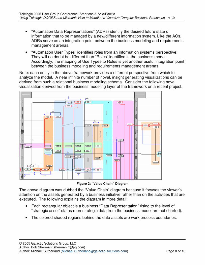
Note: each entity in the above framework provides a different perspective from which to analyze the model. A near infinite number of novel, insight generating visualizations can be derived from such a relational business modeling schema. Consider the following novel visualization derived from the business modeling layer of the framework on a recent project.
Figure 2: “Value Chain” Diagram
The above diagram was dubbed the “Value Chain” diagram because it focuses the viewer’s attention on the assets generated by a business initiative rather than on the activities that are executed. The following explains the diagram in more detail:
• Each rectangular object is a business “Data Representation” rising to the level of “strategic asset” status (non-strategic data from the business model are not charted).
• The colored shaded regions behind the data assets are work process boundaries.
Telelogic 2005 User Group Conference, Americas & Asia/Pacific Using Telelogic DOORS and Microsoft Visio to Model and Visualize Complex Business Processes – v1.0
• Each line joining data assets represents one or more “Work Process” steps. Red instances of these lines indicate a high probability of those steps being on the critical path of the business scenario.
• The orthogonal blue brackets/lines convey critical metrics.
• The gray, vertical bars identify critical stage gates in “Business Scenario”.
• The horizontal swim lanes represent the boundaries of business functions participating in the Business Scenario.
A slight change in perspective results in the following variation of the “Value Chain” diagram. The diagram below is designed to provide business process context to information system architecture decisions. The diagram is created by replacing the shaded regions representing work processes (in the above) and with shaded regions representing information system applications. Note: applications and their relationships to data are captured via the “Tools” and “Data Representations” module of the BDAL framework.
Figure 2: “Value Chain” Diagram - Variation
This type of diagram can be (and was) used to explicitly identify the business process costs of information system architecture problems.
Indeed, many insight generating diagrams can be derived can from cross-sectioning a comprehensive, relational business knowledge management model. However, it’s unlikely that such offerings to be found in commercial, off-the-shelf applications in the near future. It will take time to establish an industry standard framework/schema for housing business modeling knowledge. It will take a while longer for a set of repeatable, best-in-class, insight generating graphical renderings to emerge.
Telelogic 2005 User Group Conference, Americas & Asia/Pacific Using Telelogic DOORS and Microsoft Visio to Model and Visualize Complex Business Processes – v1.0
DOORS and the Business Driven Application Lifecycle (BDAL):
Until an industry standard framework/schema for housing business modeling knowledge emerges, avoid commercial business modeling and UML modeling tools for your business process analysis work. These tools are severely limited in the types of diagrams they support. Ironically, this limitation exists because these visual modeling tools use diagrams as the only method for populating their data models (thereby preventing rapid evolution of the diagram types).
Instead, a general purpose drawing tool like VISIO will be required to arrive at the innovative diagrams made possible by a business modeling framework. However, VISIO lacks the sophisticated back-end data models of the commercial business process engineering (BPE) and UML tools. Given this situation, how can the framework’s data be managed?
Look no further than your requirements management tool; it is far better suited for the task then the BPE and/or UML tools. The following itemizes the advantages of taking a text based approach to business modeling using DOORS.
• The granularity of traceability supported by DOORS far exceeds that of any UML and/or BPE tool.
• Unlike graphical modeling tools (like UML tools), DOORS does not impose syntax restrictions that will limit your ability to evolve the organization and format of content. Rather, DOORS provides unlimited extensibility; easily accommodating any data model and/or data view changes you’re likely to encounter.
• The multi-module, multi-attribute, dynamic traceability reporting functionality of DOORS will enable you to efficiently eliminate mistakes and omissions in the business model framework.
• The real-time change impact analysis functionality in DOORS facilitates the maintenance of referential integrity as the model evolves.
• The object level locking functionality of DOORS enables concurrent modeling of a business process. Graphical modeling tools tend to fall far short of this level of collaboration. Most require pre-partitioning of the model and many subsequent check-in/check-out operations simply to maintain visibility of the evolving business model from a central location.
• Documentation of the business model via text in DOORS is more efficient than a visual/graphical modeling approach because the latter tends to regularly divert the author’s attention away from the content to address the presentation of that content. More important, the insights generated by a presentation approach depend upon richness and diversity of perspectives that the author can draw upon in the creation of the presentation. In this case, the author will have a far richer set of perspectives upon which to draw after completing a business model than that which is possible part way through the modeling effort.
Telelogic 2005 User Group Conference, Americas & Asia/Pacific Using Telelogic DOORS and Microsoft Visio to Model and Visualize Complex Business Processes – v1.0
The manual movement and synchronization of data between DOORS and VISIO is the only outage in this approach. To address this problem, Galactic Solutions and P&G have partnered to create an integration between DOORS and VISIO. The goals of the integration were to:
• reduce the amount of time required to place DOORS content on drawings
• minimize effort required to maintain synchronization between the business models in DOORS and the VISIO based renderings of those models
Part 2 of this paper provides an overview of that DOORS/VISIO integration.
Telelogic 2005 User Group Conference, Americas & Asia/Pacific Using Telelogic DOORS and Microsoft Visio to Model and Visualize Complex Business Processes – v1.0
Part 2: Using Telelogic DOORS and Microsoft Visio to Model and Visualize the Business Driven Application Lifecycle (BDAL)
To automate Business Driven Application Lifecycle data exchange between DOORS and Visio, a DOORS Visio Interface (DVI) application has been written, The DVI is written in the DOORS Extension Language (DXL), and uses DOORS as a Microsoft automation client to control the Microsoft Visio application. Microsoft Component Object Model (COM) technology is then used to access Visio properties and methods. This technology allows the DVI to perform the necessary data access and manipulation functions to manage Visio diagrams and satisfy the DVI application requirements. Mapping The DVI allows DOORS objects to be mapped to shapes on a Visio diagram. Each mapped DOORS object is associated with a Visio master shape, and each Visio master shape is associated with a set of DOORS attributes. Mapped DOORS attributes are represented on Visio shapes as editable Visio custom properties, so that attribute value changes can be made from either application. Each mapped DOORS object can be mapped to one or more pages in the Visio drawing, and one or more layers in each page. The DVI allows DOORS links to be mapped to connectors on Visio diagrams. If two DOORS objects are mapped, and are also connected by a link in DOORS, then the linkset from the link module that the link belongs to is presented for mapping. If the linkset is subsequently mapped by the user, the DOORS links will be represented by Visio connectors glued to the Visio shapes that represent the linked DOORS objects.
Figure 4: DVI - Visio Mapping
Telelogic 2005 User Group Conference, Americas & Asia/Pacific Using Telelogic DOORS and Microsoft Visio to Model and Visualize Complex Business Processes – v1.0
Surrogate Module The DVI uses a surrogate module to represent mapped objects and relationships. For each mapped DOORS object, a surrogate object is created in the surrogate module, and a DOORS link is made from the surrogate object to the mapped object. This ensures mapped objects are not deleted unless they are first unmapped from the DVI application. Surrogate objects are also created for mapped Visio masters, DOORS attributes, and DOORS linksets. One DVI surrogate module is used for each DOORS project. Drawings The DVI manages multiple Visio drawings for each DOORS project. Visio drawings can be stored as a file on a file system, or embedded into a DOORS object. Embedding has the distinct advantage of allowing DOORS access rights to be applied to the DOORS object containing the Visio drawing.
Figure 5: DVI - Drawing Management
Telelogic 2005 User Group Conference, Americas & Asia/Pacific Using Telelogic DOORS and Microsoft Visio to Model and Visualize Complex Business Processes – v1.0
Synchronization Before the synchronization of DOORS and a Visio drawing, the user is presented with a pre-synchronization review. This review lists all changes that are necessary to synchronize DOORS and the Visio drawing, based on changes to both applications since the last synchronization. The following is a list of changes that will necessitate a synchronization action: Changes to Mappings:
• DOORS object mapped to Visio diagram • DOORS object unmapped from Visio diagram • DOORS object mapped to Visio page • DOORS object unmapped from Visio page • DOORS object mapped to Visio layer • DOORS object unmapped from Visio layer • DOORS attribute mapped to Visio master • DOORS attribute unmapped from Visio master • DOORS linkset mapped to Visio diagram • DOORS linkset unmapped from Visio diagram
Changes to data in DOORS Application: • DOORS mapped object deleted from module • DOORS mapped attribute deleted from module • DOORS link created between mapped objects • DOORS link deleted between mapped objects • DOORS attribute definition deleted • DOORS attribute type redefined • DOORS attribute value changed
Changes to data in Visio Application: • Mapped Visio shape deleted from page • Mapped Visio shape removed from mapped Visio layer • Mapped Visio shape copied and pasted • Mapped Visio connector deleted • Mapped Visio connector disconnected from Mapped Visio Shape(s) • Mapped Visio master deleted from drawing • Mapped Visio page removed from Visio diagram • Mapped Visio page renamed in Visio diagram • Mapped Visio layer removed from Visio diagram • Mapped Visio layer renamed in Visio diagram • Mapped Visio custom property value changed
Figure 6: DVI - Pre-Synchronization Review
Telelogic 2005 User Group Conference, Americas & Asia/Pacific Using Telelogic DOORS and Microsoft Visio to Model and Visualize Complex Business Processes – v1.0
Conflict Resolution Mapped DOORS attributes are represented on Visio shapes as editable Visio custom properties, and attribute value changes can be made from either application. DOORS history functionality can be used to detect the exact time and content for any changes to attribute values. Visio does not have any corresponding history functionality, so Microsoft Visio Visual Basic for Applications (VBA) macros are inserted into each DVI managed Visio drawing. These macros manage “Last Modified On” date/time stamps for the Visio custom properties representing mapped DOORS attributes. Given this situation that attribute value changes can be made from either application for mapped DOORS attributes, it is possible that a DOORS attribute value was updated for both the DOORS mapped object and the corresponding Visio shape(s) since the last synchronization. Such a case is considered a conflict, and must be resolved before synchronization. For such cases the user is presented with both changes in the pre-synchronization review, and is allowed to choose which change should prevail.
Figure 7: DVI - Pre-Synchronization Review – Conflict Resolution
Telelogic 2005 User Group Conference, Americas & Asia/Pacific Using Telelogic DOORS and Microsoft Visio to Model and Visualize Complex Business Processes – v1.0
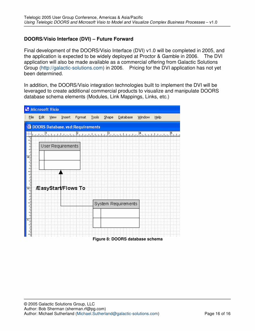
DOORS/Visio Interface (DVI) – Future Forward Final development of the DOORS/Visio Interface (DVI) v1.0 will be completed in 2005, and the application is expected to be widely deployed at Proctor & Gamble in 2006. The DVI application will also be made available as a commercial offering from Galactic Solutions Group (http://galactic-solutions.com) in 2006. Pricing for the DVI application has not yet been determined. In addition, the DOORS/Visio integration technologies built to implement the DVI will be leveraged to create additional commercial products to visualize and manipulate DOORS database schema elements (Modules, Link Mappings, Links, etc.)


![Unified Modeling Language (UML) (Chapter 6). Unified Modeling Language UML October 1994 Three Amigos Grady Booch (Rational Software) [Booch] James.](https://static.documents.pub/doc/80x56/56649cba5503460f949822be/unified-modeling-language-uml-chapter-6-unified-modeling-language-.jpg)


