Using the Web Browser Interface for Advanced Configuration TasksConfiguring Access to the Web Browser Interface
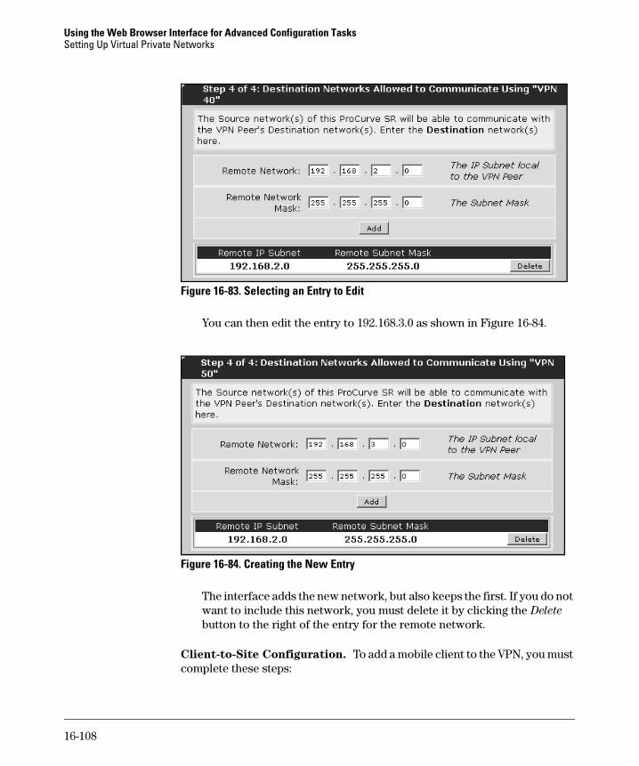
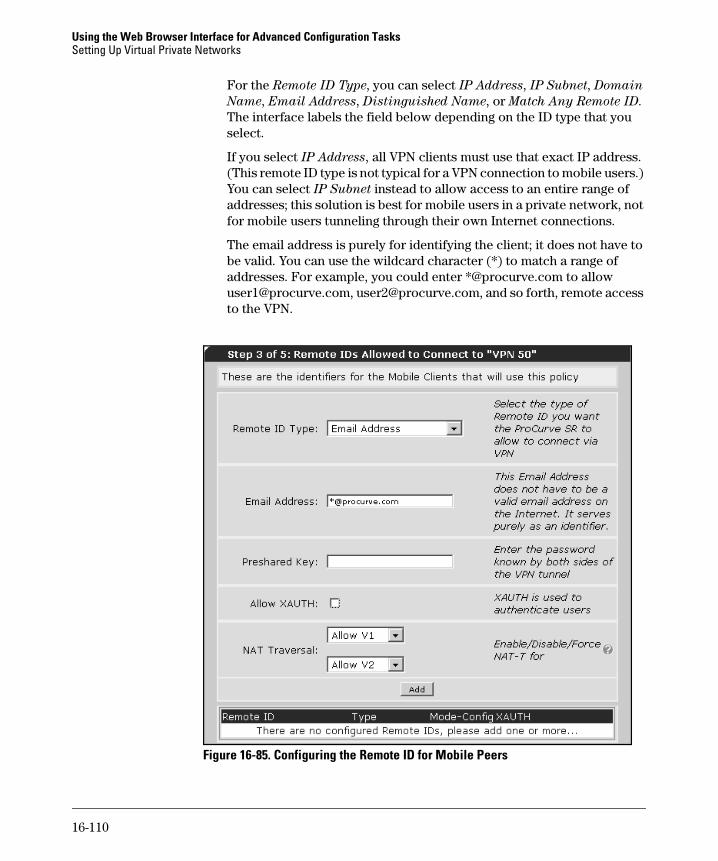
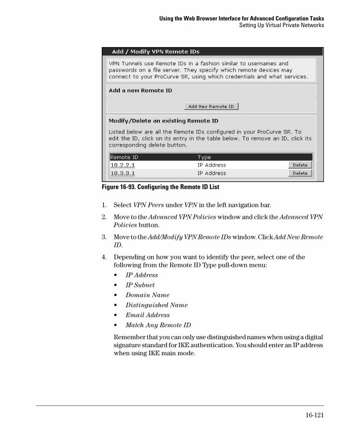
Configuring Access to the Web Browser Interface
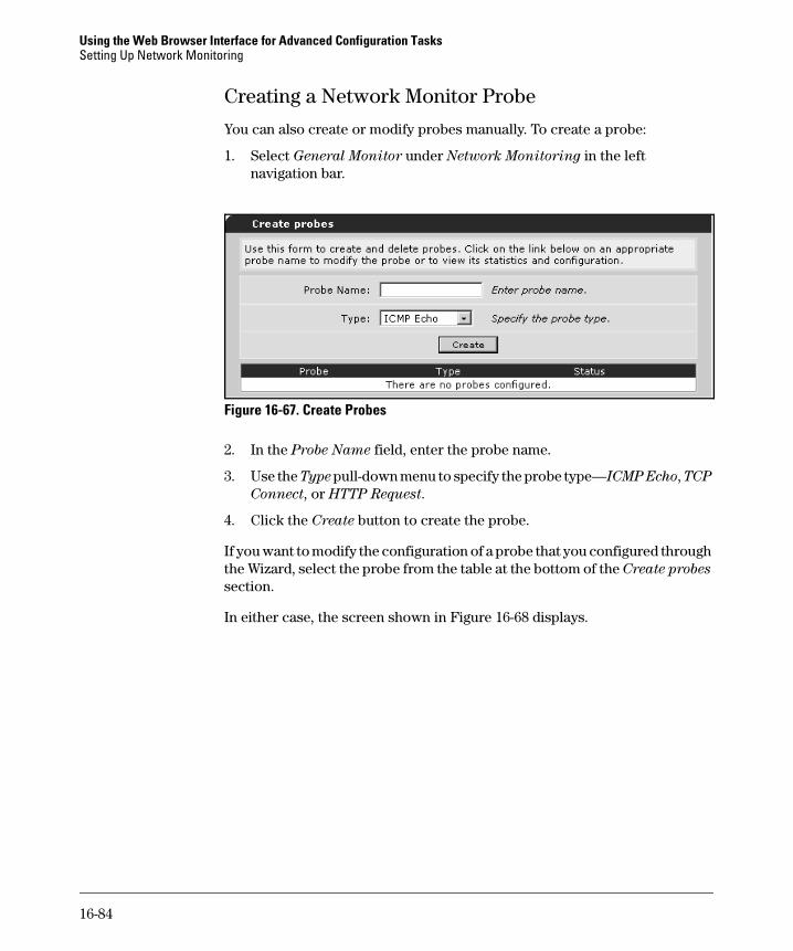
You can use the Web browser interface to configure interfaces on your router. To access the Web browser interface, you must first use the command line interface (CLI) to enable the HTTP server on the ProCurve Secure Router and to configure a username and password for HTTP access.
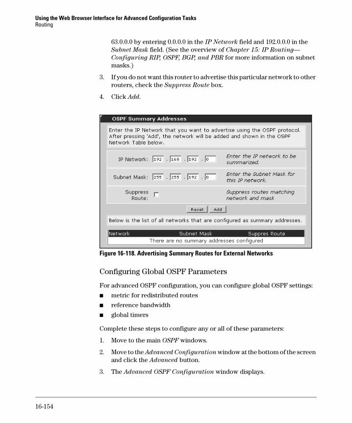
You must also configure at least one interface on the ProCurve Secure Router and establish a connection through which you can send HTTP traffic. For example, if you want to access the router from a workstation on your WAN, you must configure the Ethernet interface and establish a connection between it and your LAN. (For information about setting up an Ethernet interface, see the Basic Management and Configuration Guide, Chapter 3: Configuring
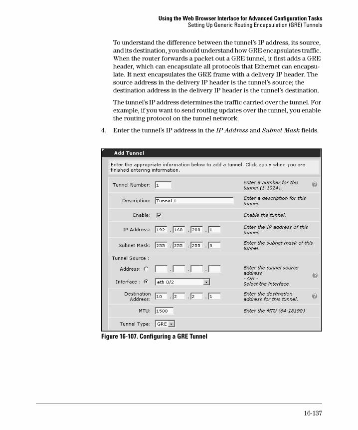
Ethernet Interfaces.
Enabling Access to the Web Browser Interface
From the global configuration mode context, enter:
ProCurve(config)# ip http server
If you want to use Secure Sockets Layer (SSL) to protect the communication between your PC and the router, enter:
ProCurve(config)# ip http secure-server
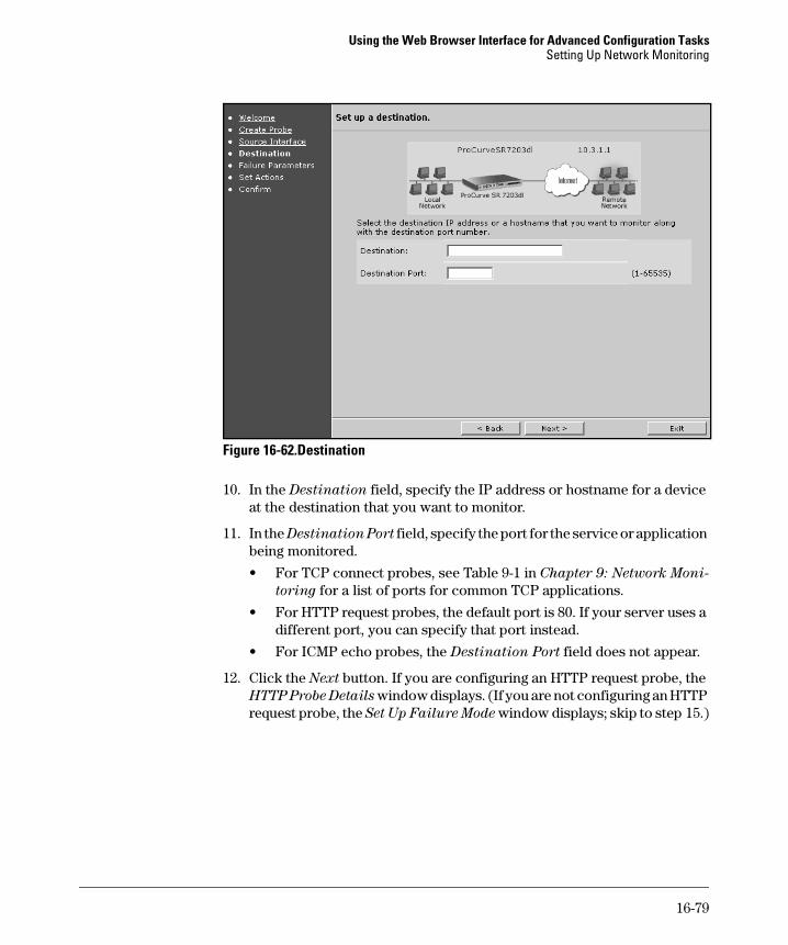
In either case, you must then configure a username and password, which will also be used for HTTP, Secure Shell (SSH), and FTP access. From the global configuration mode context, enter:
Syntax: username <username> password <password>
Both the username and password can be an alphanumeric string up to 30 characters in length. In addition, both are case-sensitive.
After configuring the ProCurve Secure Router for HTTP access, open an Internet browser and enter the IP address assigned to the router interface through which you want to establish an HTTP session. For example, if you want to access the router from your LAN and the IP address of the Ethernet 0/1 interface is 192.168.1.1, you would enter: http://192.168.1.1.You will be prompted to enter the username and password that you configured for HTTP access.
16-4
Using the Web Browser Interface for Advanced Configuration TasksThe Web Browser Interface Navigation Panel
The Web Browser Interface Navigation Panel
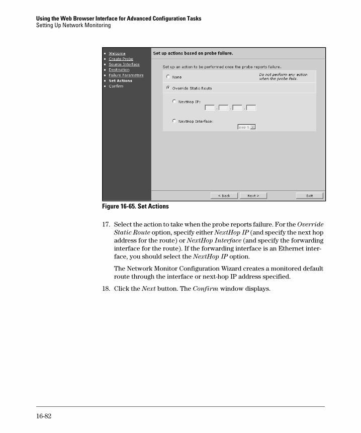
The Web browser interface features a navigation bar, containing available commands grouped by category. (See Figure 16-1.) The navigation bar is always visible on the left side of the browser screen. Selecting a command takes you to the associated screen(s) where you can view or modify settings on your ProCurve Secure Router. Although the instructions in this guide often refer to the navigation bar, it is not included in the illustrations.
Figure 16-1. Navigation Bar in the Web Browser Interface
Navigation Bar
16-5
Using the Web Browser Interface for Advanced Configuration TasksManaging AutoSynch™, Files, Firmware, Logging, and Boot Software
Managing AutoSynch™, Files, Firmware, Logging, and Boot Software
In the Utilities section of the Web browser interface, you can do basic file management tasks, manage AutoSynch™, and set the router’s firmware and boot software using the Web browser interface.
The Utilities section of the Web browser interface includes the following subsections:
■ AutoSynch™
■ Configuration
■ Firmware
■ Logging
■ Debug
■ Reboot Unit
■ Telnet to Unit
The AutoSynch™ section allows you to enable AutoSynch™ and force synchronization. For more information on AutoSynch™ functions, see the Basic Management and Configuration Guide, Chapter 1: Overview.
The Configuration section allows you to create and manage configuration files.
In the Firmware section, you can configure the router’s primary and backup firmware files, view the drive space used and free on the router’s internal flash and compact flash memories, upload, and delete firmware files.
The Debug section lets you activate debug messages that provide real-time troubleshooting information about the activity of certain interfaces, proto-cols, and operations on the router.
The Logging section lets you configure the event-history log of events logged by the Secure Router OS firewall. For more information on event logging, see “Enabling Event Logging” on page 16-30 in the Advanced Management and
Configuration Guide.
The Reboot Unit section provides two options for rebooting the router: save and reboot or reboot without saving.
The Telnet to Unit section opens a terminal session software on your PC and begins to negotiate a Telnet session between your PC and the router.
16-6
Using the Web Browser Interface for Advanced Configuration TasksManaging AutoSynch™, Files, Firmware, Logging, and Boot Software
AutoSynch™
1. To manage the AutoSynch™ feature in the Web browser interface, click AutoSynch in the Utilities section of the navigation bar. The AutoSynch Mode window is displayed. From this window, you can enable the Auto-Synch function, force synchronization, and troubleshoot AutoSynch oper-ation.
2. To enable AutoSynch™, click the AutoSynch Mode box.
3. Click Apply. This will signal the AutoSynch™ function to begin synchro-nization efforts.
N o t e The AutoSynch™ function is a feature that allows the router to maintain exact, up-to-date copies of the boot code and startup-config files on the router’s internal flash and a mounted compact flash card. The AutoSynch™ feature is not available for routers without a mounted compact flash card.
AutoSynch™ technology will work only if you have a copy of the router’s boot code file (SROS.BIZ) and a startup-config file on your compact flash card.
Figure 16-2. AutoSynch Window
16-7
Using the Web Browser Interface for Advanced Configuration TasksManaging AutoSynch™, Files, Firmware, Logging, and Boot Software
4. When the AutoSynch™ function is enabled, you can force synchronization by clicking the AutoSynch button in the AutoSynch Execute window. The following dialog box is displayed:
“You are about to activate AutoSynch. Continue?”
5. Click the OK button. The boot code file and the startup-config file will be copied from internal flash to compact flash, and synchronization will begin.
The AutoSynch Status window displays AutoSynch™ messages, such as the current synchronization status of the SROS file (SROS.BIZ) and startup-config file and any AutoSynch™ error messages. For a list of AutoSynch™ error messages and troubleshooting methods, see “AutoSynch™ Technol-ogy” on page 1-34 in the Basic Management and Configuration Guide.
Configuration
The configuration section supports basic configuration file management.
Startup-Config. The Startup-Config section allows you to set the primary and secondary startup-config files. The startup-config file contains your router’s saved configurations. If you have more than one startup configuration on internal flash or compact flash, you can set the router to boot from the file and the location you specify.
Figure 16-3. Startup Config window
After the ProCurve Secure Router boots the SROS software, it then searches for a configuration to load. By default, the router first looks on compact flash for a valid startup-config file. If it cannot find a valid startup-config on compact
16-8
Using the Web Browser Interface for Advanced Configuration TasksManaging AutoSynch™, Files, Firmware, Logging, and Boot Software
flash, it looks on the internal flash memory for a valid file. You can configure the router to load a different configuration by specifying this configuration’s filename and location.
1. Select the primary startup-config file from the pull-down menu. This menu contains a list of configuration files on the internal flash memory (and compact flash if installed).
2. To set the secondary startup-config file, select the desired configuration file from the corresponding pull-down menu.
3. To save these changes, click Apply.
N o t e If AutoSynch™ is enabled, the primary and backup startup-config files and locations are automatically set and cannot be changed.
Save-Config. The Save-Config window allows you to save the running-config file to the startup-config file. The current configurations will be saved, and the router can then boot with these configurations after it is powered down.
Click the Save button. If AutoSynch™ is enabled, the running-config is saved as startup-config on both the internal flash memory and the compact flash card.
Figure 16-4. Save Config
Download Config. The Download Config section allows you to save the startup-config to a file on your PC. This feature is particularly useful when you must configure several routers with similar settings and you need to edit the configuration to tailor it to another router.
1. Click the Download button. Depending on your browser, a File Download warning window will display. When you download the file, it is automati-cally named <hostname>-<date>.cfg. For example, if you configured your router’s hostname as HQRouter and today’s date were May 5, 2007, the filename would be HQRouter-05-05-2007.cfg.
2. Double-click the file you want to download to your PC.
16-9
Using the Web Browser Interface for Advanced Configuration TasksManaging AutoSynch™, Files, Firmware, Logging, and Boot Software
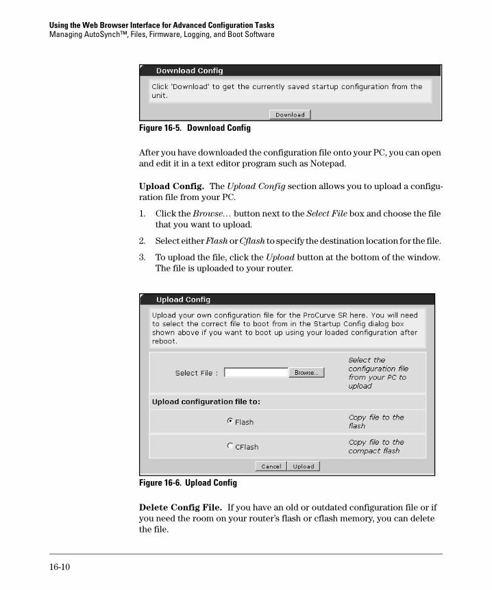
Figure 16-5. Download Config
After you have downloaded the configuration file onto your PC, you can open and edit it in a text editor program such as Notepad.
Upload Config. The Upload Config section allows you to upload a configu-ration file from your PC.
1. Click the Browse… button next to the Select File box and choose the file that you want to upload.
2. Select either Flash or Cflash to specify the destination location for the file.
3. To upload the file, click the Upload button at the bottom of the window. The file is uploaded to your router.
Figure 16-6. Upload Config
Delete Config File. If you have an old or outdated configuration file or if you need the room on your router’s flash or cflash memory, you can delete the file.
16-10
Using the Web Browser Interface for Advanced Configuration TasksManaging AutoSynch™, Files, Firmware, Logging, and Boot Software
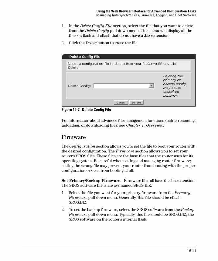
1. In the Delete Config File section, select the file that you want to delete from the Delete Config pull-down menu. This menu will display all the files on flash and cflash that do not have a .biz extension.
2. Click the Delete button to erase the file.
Figure 16-7. Delete Config File
For information about advanced file management functions such as renaming, uploading, or downloading files, see Chapter 1: Overview.
Firmware
The Configuration section allows you to set the file to boot your router with the desired configuration. The Firmware section allows you to set your router’s SROS files. These files are the base files that the router uses for its operating system. Be careful when setting and managing router firmware; setting the wrong file may prevent your router from booting with the proper configuration or even from booting at all.
Set Primary/Backup Firmware. Firmware files all have the .biz extension. The SROS software file is always named SROS.BIZ.
1. Select the file you want for your primary firmware from the Primary
Firmware pull-down menu. Generally, this file should be cflash SROS.BIZ.
2. To set the backup firmware, select the SROS software from the Backup
Firmware pull-down menu. Typically, this file should be SROS.BIZ, the SROS software on the router’s internal flash.
16-11
Using the Web Browser Interface for Advanced Configuration TasksManaging AutoSynch™, Files, Firmware, Logging, and Boot Software
Figure 16-8. Set Primary/Backup Firmware
This window also shows the current memory statistics for the internal flash and cflash drives. The Flash memory statistics are displayed as the bytes used divided by the total memory and the drive space free. The CFlash memory statistics are displayed below the Flash statistics in the same format.
It is always a good idea to keep track of the amount of memory you have available when saving multiple configurations to your router. For information about deleting files, see “Delete Config File” on page 16-10.
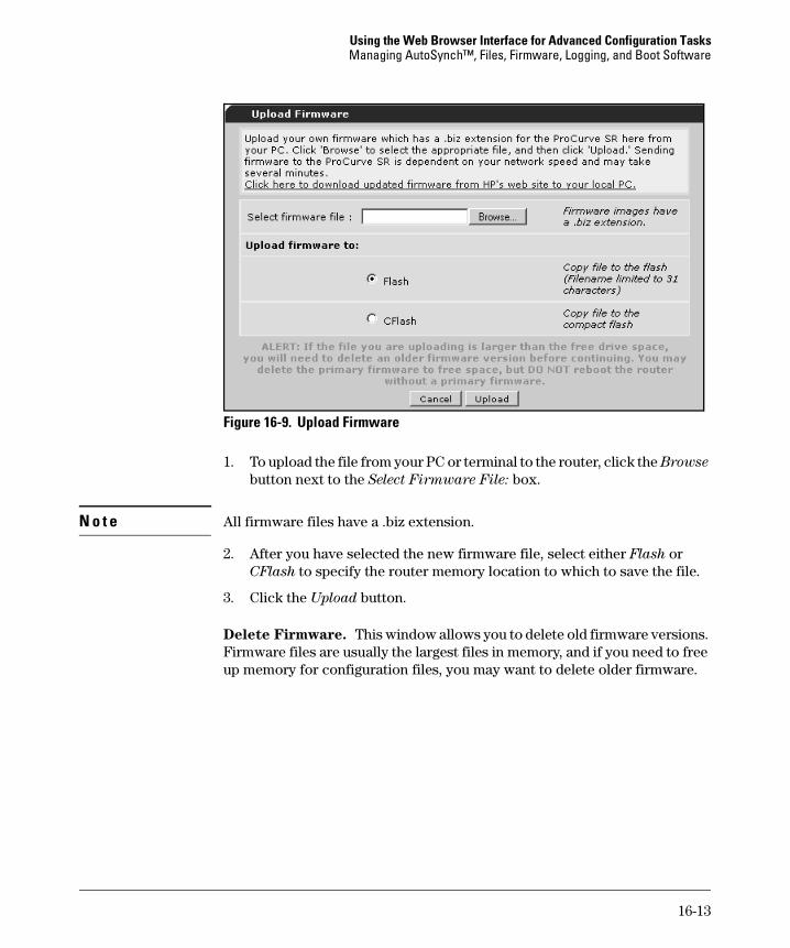
Upload Firmware. This section allows you to upload SROS updates to your router. To get these updates, go to www.procurve.com and download the new firmware files to your PC.
16-12
Using the Web Browser Interface for Advanced Configuration TasksManaging AutoSynch™, Files, Firmware, Logging, and Boot Software
Figure 16-9. Upload Firmware
1. To upload the file from your PC or terminal to the router, click the Browse
button next to the Select Firmware File: box.
N o t e All firmware files have a .biz extension.
2. After you have selected the new firmware file, select either Flash or CFlash to specify the router memory location to which to save the file.
3. Click the Upload button.
Delete Firmware. This window allows you to delete old firmware versions. Firmware files are usually the largest files in memory, and if you need to free up memory for configuration files, you may want to delete older firmware.
16-13
Using the Web Browser Interface for Advanced Configuration TasksManaging AutoSynch™, Files, Firmware, Logging, and Boot Software
Figure 16-10.Delete Firmware
1. Select the file that you want to delete from the Delete Firmware pull-down menu, which lists all files in the router’s memory that have a .biz extension.
2. Click the Delete button.
C a u t i o n Deleting the current firmware version or deleting all firmware from the router’s memory may prevent the router from booting. Be very careful when deleting your router’s firmware. You may want to keep a backup copy of the current firmware version.
Debug
The Debug section lets you activate debug messages that provide real-time information about the activity of processes and protocols that are run on the router. Debug messages are displayed as packets arrive on the router, and are useful when troubleshooting or testing your router’s operation.
The debug messages generated using the Web interface are equivalent to the corresponding CLI debug commands. For example, to view detailed messages about the network monitoring track in real time, if you select the Track filter in the Web interface, you will see the same messages that you will if you enter the CLI debug track command from the enable mode context.
You can generate messages using one or more debug filters—for example, to display track and PPP debug messages at the same time. Some debug filters have subcategories, such as the PPP filter’s Authentication subcategory (equivalent to running the CLI debug ppp authentication command). Other debug filters may require additional information, such as an access list name for the Access-List filter (as in the CLI debug access-list <listname> command).
16-14
Using the Web Browser Interface for Advanced Configuration TasksManaging AutoSynch™, Files, Firmware, Logging, and Boot Software
1. Click Debug in the Utilities section of the navigation bar.
2. To add a debug filter, click the Add Debug Filter button.
Figure 16-11. Add Debug Filter
3. From the Category pull-down menu, select the desired debug filter.
Figure 16-12. Add Debug Filter Category
a. If the debug filter that you select has subcategories, from the Subcat-
egory pull-down menu that appears, select the subcategory that you want.
Figure 16-13. Add Debug Filter Subcategory
b. Or, if the debug filter that you select requires other information, enter the information in the field provided.
16-15
Using the Web Browser Interface for Advanced Configuration TasksManaging AutoSynch™, Files, Firmware, Logging, and Boot Software
Figure 16-14. Add Debug Filter Specifics
4. Click the Apply button.
5. Repeat steps 2 through 4 for all other debug filters that you want to add.
6. If you want to delete one or more debug filters that you have selected, check the box for each filter that you want to delete. You can check or uncheck all listed categories by clicking the Debug Category box (and you can then still check or uncheck individual boxes as needed). Then click the Remove Selected Events button to delete all checked filters.
Figure 16-15. Start Debug
16-16
Using the Web Browser Interface for Advanced Configuration TasksManaging AutoSynch™, Files, Firmware, Logging, and Boot Software
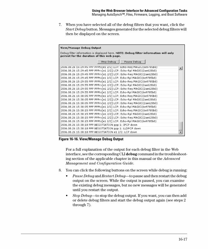
7. When you have selected all of the debug filters that you want, click the Start Debug button. Messages generated for the selected debug filters will then be displayed on the screen.
Figure 16-16. View/Manage Debug Output
For a full explanation of the output for each debug filter in the Web interface, see the corresponding CLI debug command in the troubleshoot-ing section of the applicable chapter in this manual or the Advanced
Management and Configuration Guide.
8. You can click the following buttons on the screen while debug is running:
• Pause Debug and Restart Debug—to pause and then restart the debug output on the screen. While the output is paused, you can examine the existing debug messages, but no new messages will be generated until you restart the output.
• Stop Debug—to stop the debug output. If you want, you can then add or delete debug filters and start the debug output again (see steps 2 through 7).
16-17
Using the Web Browser Interface for Advanced Configuration TasksManaging AutoSynch™, Files, Firmware, Logging, and Boot Software
C a u t i o n If you click the Stop Debug, Add Debug Filter, or Remove Selected Events button while debug is running, the current debug output on the screen will be lost.
As you use the debug commands in the Web interface to troubleshoot your router, be aware that debug operations are processor-intensive and could seriously degrade network performance.
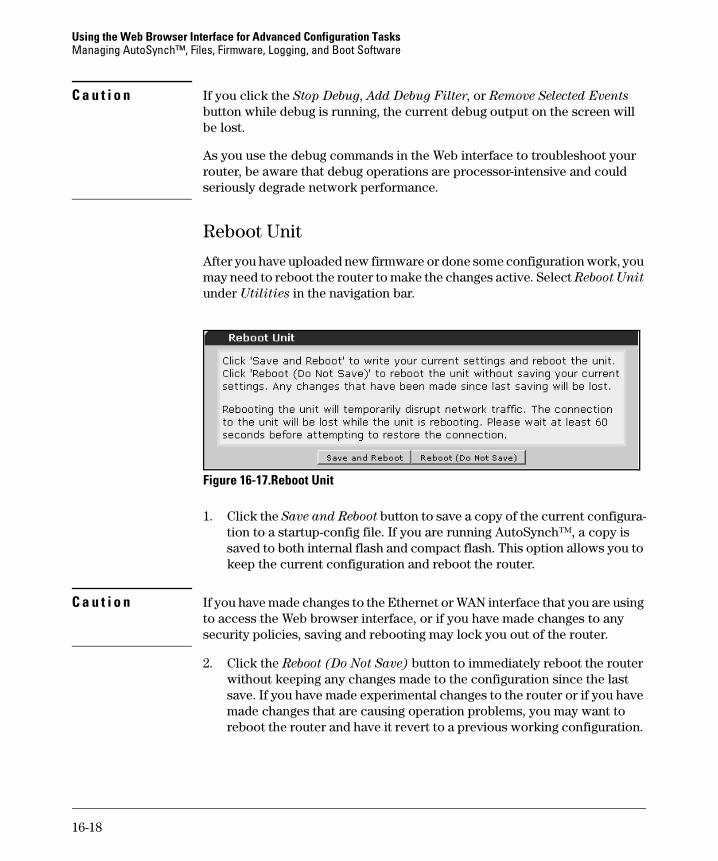
Reboot Unit
After you have uploaded new firmware or done some configuration work, you may need to reboot the router to make the changes active. Select Reboot Unit under Utilities in the navigation bar.
Figure 16-17.Reboot Unit
1. Click the Save and Reboot button to save a copy of the current configura-tion to a startup-config file. If you are running AutoSynch™, a copy is saved to both internal flash and compact flash. This option allows you to keep the current configuration and reboot the router.
C a u t i o n If you have made changes to the Ethernet or WAN interface that you are using to access the Web browser interface, or if you have made changes to any security policies, saving and rebooting may lock you out of the router.
2. Click the Reboot (Do Not Save) button to immediately reboot the router without keeping any changes made to the configuration since the last save. If you have made experimental changes to the router or if you have made changes that are causing operation problems, you may want to reboot the router and have it revert to a previous working configuration.
16-18
Using the Web Browser Interface for Advanced Configuration TasksManaging AutoSynch™, Files, Firmware, Logging, and Boot Software
Telnet to Unit
To open a Telnet session between your router and your PC, select Telnet to
Unit under Utilities in the navigation bar.
In order to successfully establish a Telnet session to your router, you first need to configure the router to allow Telnet access.
1. Set an enable mode password.
a. On the left panel of the Web browser interface, click Passwords.
b. Scroll to the Service Authentication window and click the Enable tab.
c. Select Use Password and enter an enable password. Enter the pass-word again in the Confirm Password box.
d. Click Apply.
2. Set a Telnet password.
a. In the Service Authentication window, click the Telnet tab.
b. Select Use Password and enter the password in the box. Re-enter the password in the Confirm Password box.
3. In the navigation bar, click Telnet to Unit. The PC will open a terminal session and begin to establish a Telnet session.
4. When the terminal session software begins, it will prompt you for a password. Enter the Telnet password.
5. The session software will display the CLI in the basic mode context. To enter the enable mode context, enter enable. When the router prompts you for the enable mode password, enter the password you configured. From this Telnet session, you can configure the router using the CLI.
16-19
Using the Web Browser Interface for Advanced Configuration TasksEnabling IP Services on the Router
Enabling IP Services on the Router
In the IP Services section, you can enable or disable the following servers on the router:
■ FTP
■ TFTP
■ HTTP
■ HTTPS
■ secure copy
■ Telnet
■ SSH
You can also configure settings for the Web browser interface.
In addition to enabling these servers, you must configure passwords for them so that users can access the router. To configure passwords for management access, see “Configuring Passwords to Control Management Access to the Router” on page 14-26 of the Basic Management and Configuration Guide.
1. Click System > IP Services in the left navigation bar. The IP Services
Enable/Disable window is displayed.
16-20
Using the Web Browser Interface for Advanced Configuration TasksEnabling IP Services on the Router
Figure 16-18.IP Services Enable/Disable
2. To enable the router as an FTP server, check the box.
3. To enable the router as a TFTP server, check the box.
4. To access the Web browser interface, you enabled the router’s HTTP server from the CLI. To disable the HTTP server, uncheck the box.
16-21
Using the Web Browser Interface for Advanced Configuration TasksEnabling IP Services on the Router
C a u t i o n Disabling the HTTP Server will cause the Web browser interface to stop functioning.
5. To change port for the HTTP server, enter the desired port number in the box. The default port is 80.
6. To enable the HTTPS server, check the box.
7. To change the port for HTTPS server, enter the desired port number in the box. The default is 443.
8. To enable the router’s Secure Copy Server, check the box.
9. To enable the router as a Telnet server, check the box.
10. To change the Telnet Server Port, enter the desired port number in the box. The default port is 23.
11. To enable the router as an SSH server, check the box.
12. To change the SSH Server Port, enter the desired port number in the box. The default port is 22.
13. To make the changes effective, click Apply. If you want to return to the previously configured settings, click Cancel instead.
Web Access Configuration
Web sessions with the ProCurve Secure Router have a default timeout of 10 minutes, after which you must log in again for continued access to the Web browser interface.
16-22
Using the Web Browser Interface for Advanced Configuration TasksEnabling IP Services on the Router
Figure 16-19. Web Access Configuration
1. To change the Inactivity Timeout, enter the number of hours, minutes, and seconds in the boxes.
2. You can set the maximum number of concurrent connections to the Web browser interface by entering the number in the Max Sessions box.
3. To make the changes effective, click Apply. Click Cancel to reset to the previously configured settings.
16-23
Using the Web Browser Interface for Advanced Configuration TasksIncreasing Bandwidth
Increasing Bandwidth
Link-aggregation protocols allow a router to bundle multiple carrier-lines into a single logical connection to a peer. Link-aggregation allows you to increase the bandwidth on your router without purchasing an expensive T3 or E3 line.
The ProCurve Secure Router supports:
■ Multilink Point-to-Point Protocol (MLPPP)
■ Multilink Frame Relay (MLFR)
Configuring MLPPP
1. In the left navigation bar, select Physical Interfaces.
2. Choose the interface for the first physical carrier-line.
3. The Configuration window for the physical interface will display. If you have not already done so, configure the interface as described in “Config-uring E1 and T1 Interfaces” on page 14-54 of the Basic Management and
Configuration Guide.
4. If you have not already done so, click the Encapsulation circle and select PPP.
5. Check the Multilink box.
6. A PPP Multilink Interface section will display:
a. If you have already configured the PPP interface for the connection, choose Select. Choose the PPP interface from the pull-down menu.
b. If you have not configured the PPP interface for the connection, choose New.
7. Click Apply.
8. The Configuration window for the PPP interface will open. If you have not already done so, configure the interface as described in “Configure PPP as the Data Link Layer Protocol” on page 14-62 of the Basic Manage-
ment and Configuration Guide.
9. Again select Physical Interfaces from the left navigation bar.
16-24
Using the Web Browser Interface for Advanced Configuration TasksIncreasing Bandwidth
10. Click the name of the interface for the second physical carrier-line to move to its Configuration window. If necessary, configure the interface as described in “Configuring E1 and T1 Interfaces” on page 14-54 of the Basic
Management and Configuration Guide.
11. Select PPP as the Encapsulation type and check the Multilink box.
12. In the PPP Multilink Interface section, click Select. Choose the same PPP interface that you chose or configured in step 6.
13. Click Apply.
14. Repeat steps 8 through 13 for any additional carrier-lines.
Figure 16-20. Configuring Multilink Protocols
16-25
Using the Web Browser Interface for Advanced Configuration TasksIncreasing Bandwidth
Configuring MLFR
1. In the left navigation bar, select Physical Interfaces.
2. Choose the interface for the first physical carrier-line.
3. You will move to the physical interface’s Configuration window. If you have not already done so, configure the interface as described in “Config-uring E1 and T1 Interfaces” on page 14-54 of the Basic Management and
Configuration Guide.
4. If you have not already done so, click the Encapsulation circle and select Frame Relay.
5. Check the Multilink box.
6. A Frame Relay Multilink Interface section will display:
a. If you have already configured the Frame Relay interface for the connection, choose Select. Choose the Frame Relay interface from the pull-down menu.
b. If you have not configured the Frame Relay interface for the connec-tion, choose New.
7. Click Apply.
8. The Frame Relay Configuration window will open. If you have not already done so, configure the interface as described in “Configure Frame Relay as the Data Link Layer Protocol” on page 14-68 of the Basic
Management and Configuration Guide. If you have not already done so, you must establish at least one PVC.
9. Again select Physical Interfaces from the left navigation bar.
10. Choose the name of the interface for the second physical carrier-line. If necessary, configure the interface as described in “Configuring E1 and T1 Interfaces” on page 14-54 of the Basic Management and Configuration
Guide.
11. Select Frame Relay for the Encapsulation and check the Multilink box.
12. In the Frame Relay Multilink Interface section, click Select. Choose the same Frame Relay interface that you chose or configured in step 6.
13. Click Apply.
14. Repeat steps 8 through 13 for any additional carrier-lines.
16-26
Using the Web Browser Interface for Advanced Configuration TasksBackup Modules
Backup Modules
The ProCurve Secure Router supports Basic Rate Interface (BRI) Integrated Services Digital Network (ISDN) and analog backup. You must purchase and install a backup module to activate backup. You must then configure backup settings from the CLI. See Chapter 3: Configuring Backup WAN Connections for information about configuring backup interfaces.
The ProCurve Secure Router also provides backup with demand routing. To learn how to configure this feature, see “Configuring Demand Routing for a Primary or Backup Connection” on page 14-88 in the Basic Management and
Configuration Guide, Chapter 14: Using the Web Browser Interface for Basic
Configuration Tasks.
Configuring the ProCurve Secure Router OS Firewall
The ProCurve Secure Router OS firewall is a stateful-inspection firewall, which incorporates the functions of:
■ a packet-filtering firewall
■ circuit level gateway
■ application level gateway
As a packet-filtering firewall, the Secure Router OS firewall checks the IP header of every packet that arrives on a router interface. The router only forwards packets that have permitted values in their headers—for example, a permitted source IP address. You control which packets the firewall permits by configuring access control lists (ACLs) and access control policies (ACPs). For more information, see “Configuring Access Control from the Web Browser Interface” on page 16-41.
As a circuit level gateway, the Secure Router OS firewall monitors the estab-lishment of sessions between trusted and untrusted hosts. The firewall auto-matically blocks packets with TCP headers associated with known attacks. See Table 16-1 for a list of these attacks.
16-27
Using the Web Browser Interface for Advanced Configuration TasksConfiguring the ProCurve Secure Router OS Firewall
Table 16-1. Packets Automatically Dropped by the Secure Router OS Firewall
Packet Associated Attack
larger than the IP max (65,535 bytes) Ping of death
falsified IP header (the length bit does not match the actual length)
• Jolt• Jolt2
UDP echo packets • Chargen• Fraggle
source address equals the destination address
Land attack
broadcast address for the source address —
TCP SYN packets with one or more of these flags:• ACK• URG• RST• FIN
—
invalid TCP sequence number —
source route option is enabled —
16-28
Using the Web Browser Interface for Advanced Configuration TasksConfiguring the ProCurve Secure Router OS Firewall
Unlike a true circuit level gateway, the Secure Router OS firewall does not establish a proxy session to the untrusted host on behalf of the trusted host, which saves processor power. You can configure Network Address Transla-tion (NAT) to assign internal hosts a public address. See “Configuring NAT” on page 16-50.
Application level gateways (ALGs) provide the special handling some appli-cations need to run properly through a firewall. Each application has a unique ALG. You can enable and disable the following ALGs on the ProCurve Secure Router:
■ H.323
■ File Transfer Protocol (FTP)
■ Session Initiation Protocol (SIP)
■ Point-to-Point Tunneling Protocol (PPTP)
Other options you can configure for the Secure Router OS firewall from the ProCurve Secure Router interface include:
■ TCP stealth mode
■ the timeout for TCP, UDP, and ICMP sessions
The firewall wizard helps you to configure:
■ many-to-one NAT so that internal hosts can access the Internet using the public address of a router interface
■ port forwarding so that Internet users can access servers on your network
Enabling Attack Checking
1. In the left navigation bar, select General Firewall under Firewall.
2. Select the General Settings tab.
3. Check the Enable box.
4. Click Apply.
5. You can check the Stealth TCP Mode box and click Apply to enable stealth mode. Hackers sometimes use port scanners to map out ports that are open and closed on a router. When operating in stealth mode, the ProCurve Secure Router does not send an RST packet when a host requests a TCP session on a closed port. Stealth mode thus prevents attackers from learning whether a particular port is open or closed.
16-29
Using the Web Browser Interface for Advanced Configuration TasksConfiguring the ProCurve Secure Router OS Firewall
Figure 16-21. Configuring General Firewall Settings
After you enable the firewall, the ProCurve Secure Router automatically guards against all attacks shown in Table 16-1 on page 16-28, as well as against SYN-floods. You can only enable checks for WinNuke attacks from the CLI. You can also disable SYN-flood protection from the CLI.
Enabling Event Logging
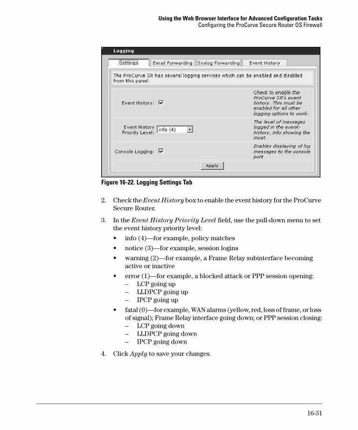
Use the settings on the Settings tab to enable event history, set the priority level for events, and specify whether or not you want the event history messages to be displayed on the CLI.
1. Click Logging in the Utilities section of the navigation bar, and then select the Settings tab.
16-30
Using the Web Browser Interface for Advanced Configuration TasksConfiguring the ProCurve Secure Router OS Firewall
Figure 16-22. Logging Settings Tab
2. Check the Event History box to enable the event history for the ProCurve Secure Router.
3. In the Event History Priority Level field, use the pull-down menu to set the event history priority level:
• info (4)—for example, policy matches
• notice (3)—for example, session logins
• warning (2)—for example, a Frame Relay subinterface becoming active or inactive
• error (1)—for example, a blocked attack or PPP session opening:– LCP going up– LLDPCP going up– IPCP going up
• fatal (0)—for example, WAN alarms (yellow, red, loss of frame, or loss of signal); Frame Relay interface going down; or PPP session closing:– LCP going down– LLDPCP going down– IPCP going down
4. Click Apply to save your changes.
16-31
Using the Web Browser Interface for Advanced Configuration TasksConfiguring the ProCurve Secure Router OS Firewall
Enabling Email Forwarding
Use the settings on the Email Forwarding tab to forward logs and exception reports to email addresses. (By default, when a failure event occurs, the ProCurve Secure Router automatically generates an exception report and saves the report to a file in internal flash. Failure reports include core dumps and fatal errors.)
1. Select the Email Forwarding tab on the Logging screen.
Figure 16-23.Email Forwarding Tab
2. Check the Email Forwarding box to enable email forwarding of event reports.
16-32
Using the Web Browser Interface for Advanced Configuration TasksConfiguring the ProCurve Secure Router OS Firewall
3. In the Email Forwarding Priority Level field, use the pull-down menu to set the email forwarding priority level:
• info (4)
• notice (3)
• warning (2)
• error (1)
• fatal (0)
4. In the Email Server field, enter either the IP address or the DNS name for the email server for the users who will receive logs.
5. In the Email Receiver List field, enter the email addresses to which you want to send the logs.
6. In the Exception Report Receiver List field, enter the email addresses for the users who will receive any exception reports generated on the router.
7. In the Email Sender field, enter the name that will appear in the sender field for the messages that the ProCurve Secure Router sends.
8. Click Apply to save your changes.
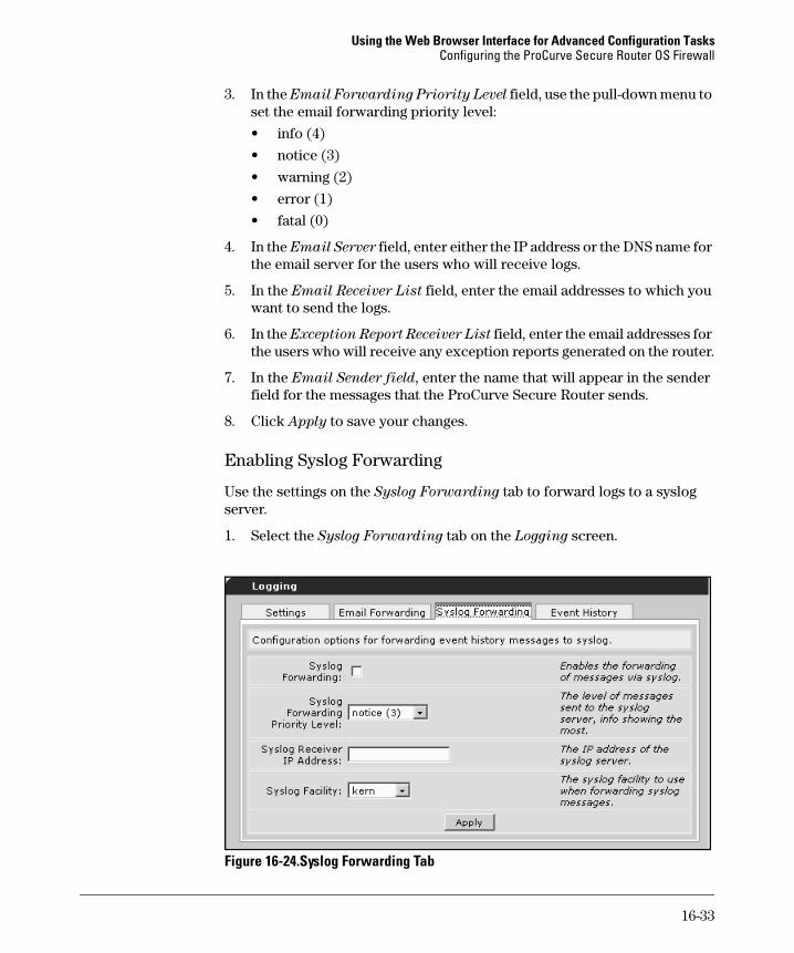
Enabling Syslog Forwarding
Use the settings on the Syslog Forwarding tab to forward logs to a syslog server.
1. Select the Syslog Forwarding tab on the Logging screen.
Figure 16-24.Syslog Forwarding Tab
16-33
Using the Web Browser Interface for Advanced Configuration TasksConfiguring the ProCurve Secure Router OS Firewall
2. Check the Syslog Forwarding box to enable syslog forwarding.
3. In the Syslog Forwarding Priority Level field, use the pull-down menu to set the email forwarding priority level:
• info (4)
• notice (3)
• warning (2)
• error (1)
• fatal (0)
4. In the Syslog Receiver IP Address field, enter the IP address of the syslog server.
5. In the Syslog Facility field, use the pull-down menu to select the facility used by other routers on your network.
Originally, the syslog facility was used to identify which part of a UNIX system originated a particular message. This system does not define a router as part of the UNIX system, but the local0 through local7 facilities are typically reserved for messages from remote devices.
6. Click Apply to save your changes.
Display the Event History
To view the router’s event history from the Web browser interface, click the Event History tab on the Logging screen.
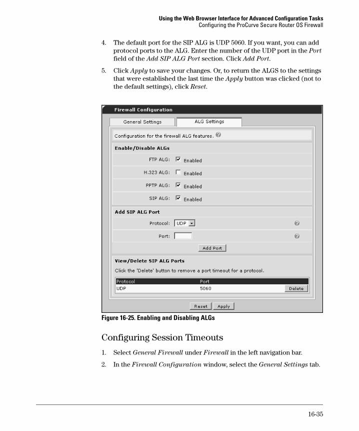
Enabling ALGs
These ALGs are enabled by default:
■ FTP
■ SIP
■ PPTP
The H.323 ALG is disabled by default.
To configure the ALGs, follow these steps:
1. Under Firewall in the left navigation bar, select General Firewall.
2. Select the ALG Settings tab.
3. Check the boxes for the ALGs that you want to enable. Uncheck the box to disable the ALG.
16-34
Using the Web Browser Interface for Advanced Configuration TasksConfiguring the ProCurve Secure Router OS Firewall
4. The default port for the SIP ALG is UDP 5060. If you want, you can add protocol ports to the ALG. Enter the number of the UDP port in the Port field of the Add SIP ALG Port section. Click Add Port.
5. Click Apply to save your changes. Or, to return the ALGS to the settings that were established the last time the Apply button was clicked (not to the default settings), click Reset.
Figure 16-25. Enabling and Disabling ALGs
Configuring Session Timeouts
1. Select General Firewall under Firewall in the left navigation bar.
2. In the Firewall Configuration window, select the General Settings tab.
16-35
Using the Web Browser Interface for Advanced Configuration TasksConfiguring the ProCurve Secure Router OS Firewall
3. You can alter the settings for the default TCP, UDP, and ICMP timeouts. These settings determine when the router will timeout any inactive TCP, UDP, or ICMP session for which you do not set an override timeout (see below). Enter the time in hours, minutes, and seconds in the fields to the left of each label. See Figure 16-21 on page 16-30.
4. Click Apply to save your changes.
Figure 16-26. Configuring Individual TCP and UDP Timeouts
5. You can also set different timeouts for specific TCP and UDP protocols. These settings override the global, default setting.
a. In the General Firewall window, move to the Add/Modify/Delete IP
Policy Timeout window.
b. Select TCP or UDP from the Protocol pull-down menu.
c. Select the specific application from the Port Type pull-down menu.
d. Enter the session timeout in hours, minutes, and seconds in the fields to the left of the corresponding labels.
e. Click Add/Modify.
16-36
Using the Web Browser Interface for Advanced Configuration TasksConfiguring the ProCurve Secure Router OS Firewall
f. You can delete timeout policies that have already been added. These policies are listed below the Add/Modify button in the Delete Entries section. Click the Delete button to the right of the specific policy timeout.
Using the Firewall Wizard
The firewall wizard helps you to quickly configure NAT on a router that connects to the Internet. The firewall wizard enables the router to:
■ perform many-to-one NAT on all traffic outbound to the Internet
■ perform port forwarding to allow external traffic to internal servers
■ drop all other external traffic
N o t e The firewall wizard overwrites policies applied to both the private and public interface. You should therefore use the firewall wizard before configuring other security policies. You can then customize policies as described in “Configuring Access Control from the Web Browser Interface” on page 16-41.
To use the firewall wizard to configure NAT:
1. Select Firewall Wizard under Firewall in the left navigation bar. The wizard will display in a new window.
2. The wizard warns you that it will overwrite previous configurations. Click Next. The router must have at least two IP interfaces (a private and a public) for the firewall wizard to proceed.
3. Select the interface that connects to the Internet from the Interface pull-down menu.
4. If Internet users do not need to access any servers internal to your network, move to step 9.
16-37
Using the Web Browser Interface for Advanced Configuration TasksConfiguring the ProCurve Secure Router OS Firewall
Figure 16-27. Permitting Internet Users to Access an Internal Server
5. If your private network includes a server that Internet users need to access, specify it in the Port Forwarding window. Select the server type from the list under Yes. You can select:
• Web server
• FTP server
• E-mail server
• Telnet server
• Other server
Click Next.
6. The wizard displays a new window in which you can specify the server’s private IP address. Enter the address and click Next.
16-38
Using the Web Browser Interface for Advanced Configuration TasksConfiguring the ProCurve Secure Router OS Firewall
Figure 16-28. Specifying the Internal Server’s Address
7. The wizard displays the original Port Forwarding window. You can now add a second server.
8. Repeat steps 5 through 7 until you have specified an IP address for every server that Internet users must be able to access.
9. Select No in the Port Forwarding window. Click Next.
16-39
Using the Web Browser Interface for Advanced Configuration TasksConfiguring the ProCurve Secure Router OS Firewall
Figure 16-29. Viewing Settings Established by the Firewall Wizard
10. Review the NAT settings in the Confirm Settings window. All hosts that connect through the Private Interface will use the address on the public interface. You can use the Back button to fix a misconfiguration or add a server. You can also select a window from the left navigation bar.
11. If the settings are correct, click Finish.
12. Click Exit to return to the main window.
If necessary, you can now customize settings by editing the Public and Private security zones. See the next section, “Configuring Access Control from the Web Browser Interface” on page 16-41.
16-40
Using the Web Browser Interface for Advanced Configuration TasksConfiguring Access Control from the Web Browser Interface
Configuring Access Control from the Web Browser Interface
If you use the Web browser interface to configure access controls on router interfaces, you must first enable the Secure Router OS firewall. In the left navigation bar, select General Firewall under Firewall. Under Configuration
for Firewall, select the Enable box and click Apply.
You can then begin to configure access control lists (ACLs), as well as security zones—the term used for access control policies (ACPs) in the Web browser interface. For more information about ACLs and ACPs, see Chapter 5: Apply-
ing Access Control to Router Interfaces.
N o t e If you configure ACLs from the CLI and apply these ACLs directly to a router interface, you do not need to enable the Secure Router OS firewall. The firewall is required when you use ACLs in conjunction with ACPs.
Configuring Access Control Lists (ACLs)
Use the settings on the Settings tab to enable event history, set the priority level for events, and specify whether or not you want the event history messages to be displayed on the CLI.
1. Click General Firewall in the Firewall section of the navigation bar.
Figure 16-30. Configure ACLs
2. In the Access Control Lists section at the bottom of the screen, click the Configure ACLs button.
16-41
Using the Web Browser Interface for Advanced Configuration TasksConfiguring Access Control from the Web Browser Interface
Figure 16-31. Add or Modify ACLs
3. In the ACL Name field, enter a name for the ACL.
4. In the ACL Type field, select Extended. (This selection gives you more control in configuring the ACL.)
6. On the Add/Modify/Delete Policy Traffic Selectors screen, click the Add
New Traffic Selector button.
16-42
Using the Web Browser Interface for Advanced Configuration TasksConfiguring Access Control from the Web Browser Interface
Figure 16-33. Add New Custom Policy Entry
7. On the Add New Custom Policy Entry screen, in the Filter Type field, select either:
• Permit to define traffic that will initiate the dial-up connection
• Deny to define traffic that will be ignored
8. In the Protocol field, use the pull-down menu to select traffic based on a particular protocol. Use the ICMP Message Type (ICMP Only) option to define ICMP traffic.
9. In the Source Data section, define the source IP address and port.
16-43
Using the Web Browser Interface for Advanced Configuration TasksConfiguring Access Control from the Web Browser Interface
10. In the Destination Data section, define the destination IP address and port.
11. Click the Apply button to save your changes.
The permit or deny statement that you configured is listed on the Add/Modify/
Delete Traffic Selectors screen.
Configuring Access Control Policies (ACPs)
1. Click Security Zones in the Firewall section of the navigation bar. The Edit Security Zones window is displayed.
Figure 16-34. Configuring Security Zones
2. Click the Rename button next to the Security Zone that you want to edit. The Configure Security Zone Name window is displayed.
Figure 16-35. Configure Security Zone Name Window
3. Enter a name for the security zone and click Apply. The Configure Policies
for Security Zone window is displayed.
16-44
Using the Web Browser Interface for Advanced Configuration TasksConfiguring Access Control from the Web Browser Interface
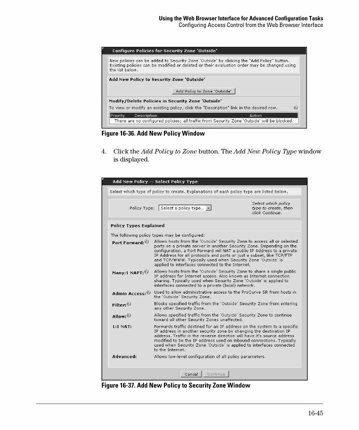
Figure 16-36. Add New Policy Window
4. Click the Add Policy to Zone button. The Add New Policy Type window is displayed.
Figure 16-37. Add New Policy to Security Zone Window
16-45
Using the Web Browser Interface for Advanced Configuration TasksConfiguring Access Control from the Web Browser Interface
From this window, you can:
• filter, or block, traffic—see “Filtering, or Blocking, Traffic” on page 16-46
• allow traffic—see “Allowing Traffic” on page 16-48
• configure NAT—see “Configuring NAT” on page 16-50
• control administrative access to the router—see “Configuring Poli-cies to Control Management Access to the ProCurve Secure Router” on page 16-53
• configure advanced policies—see “Customizing Your Policies” on page 16-53
Filtering, or Blocking, Traffic
1. To block certain traffic from entering an interface, use the pull-down menu to select Filter for the Policy Type in the Add New Policy window. Click Continue. The Add New Policy to Security Zone window is dis-played.
Figure 16-38. Filtering, or Blocking, Traffic Entering an Interface
16-46
Using the Web Browser Interface for Advanced Configuration TasksConfiguring Access Control from the Web Browser Interface
2. Enter a policy descriptor, which will be displayed when you view the running-config. For example, you may want to document how the ACP is going to be used. You could enter:
Control access to Eth 0/1 interface
N o t e To view the running-config, you must enter the show running-config com-mand from the enable mode context in the CLI.
3. In the Protocol pull-down menu, select a protocol from the following choices:
• any
• Specified
• tcp
• udp
• icmp
• gre
• esp
• ahp
If you select Specified, enter the number for the protocol in the field to the right.
4. For Source IP Address/Mask, select Any or enter a specific IP address or a specific subnet.
5. Select a Destination IP Address/Mask. Again, you can select any or enter a specific IP address or a specific subnet.
6. If you have selected TCP or UDP for the protocol, you can specify a port in the Filtered Ports section.
a. You can select Any, choose a port from the list of well-known ports, or enter a specific port.
b. To enter a specific port, choose Specified. Then use the pull-down menu below to select: – Equal To—the policy only filters the port that you enter in the
box to the right– Range—the policy filters all ports in the range that you specify– Greater Than—the policy filters all ports greater than the port
that you specify– Not Equal To—the policy filters all ports except the port that you
specify– Less Than—the policy filters all ports less than the port that you
specify
16-47
Using the Web Browser Interface for Advanced Configuration TasksConfiguring Access Control from the Web Browser Interface
7. Click Apply. The policy you created is now listed on the Configure
Policies for Security Zone window.
Allowing Traffic
1. To allow certain traffic to enter an interface, use the pull-down menu to select Allow for the Policy Type in the Add New Policy window. Click Continue. The Add New Policy to Security Zone window is displayed.
Figure 16-39. Permitting Traffic to Enter an Interface
2. Enter a policy descriptor, which will be displayed when you view the running-config. For example, you may want to use the policy descriptor to document how the ACP is going to be used. You could enter:
Control access to Eth 0/1 interface
16-48
Using the Web Browser Interface for Advanced Configuration TasksConfiguring Access Control from the Web Browser Interface
3. Enable Stateless Processing, if applicable. Stateless Processing will allow certain IP phones or POS stations to work in situations where stateful TcP processing prevents these devices from working.
4. Select a Destination Security Zone from the following choices:
• Any
• Self-bound
• <other named zones>
The policy you are configuring will only be applied if the traffic is destined for this specific security zone.
5. Select a protocol from the following choices:
• any
• Specified
• tcp
• udp
• icmp
• gre
• esp
• ahp
If you select Specify, enter the number for the protocol in the field to the right.
6. For Source IP Address/Mask, select any or enter a specific IP address or a specific subnet.
7. Select a Destination IP Address/Mask. Again, you can select any or enter a specific IP address or a specific subnet.
8. If you have selected TCP or UDP for the protocol, you can specify a port in the Filtered Ports section.
a. You can select Any, choose a port from the list of well-known ports, or enter a specific port.
16-49
Using the Web Browser Interface for Advanced Configuration TasksConfiguring Access Control from the Web Browser Interface
b. To enter a specific port, choose Specified. Then use the pull-down menu below to select: – Equal To—the policy only filters the port that you enter in the
box to the right– Range—the policy filters all ports in the range that you specify– Greater Than—the policy filters all ports greater than the port
that you specify– Not Equal To—the policy filters all ports except the port that you
specify– Less Than—the policy filters all ports less than the port that you
specify
9. Click Apply. The policy you created is now listed on the Configure
Policies for Security Zone window.
Configuring NAT
You can configure the following:
■ Many-to-one NAT—allows multiple devices on the internal network to share one public IP address as they access the Internet. Many-to-one NAT is based on the source address.
■ One-to-one NAT—allows Internet users to access a device on the internal network. A public IP address is advertised on the Internet, but the device on the internal network is actually using a private IP address. When the ProCurve Secure Router receives a packet addressed to the advertised public IP address, it translates this address to the actual private IP address that the device is using. One-to-one NAT is based on the destination IP address.
Configuring Many-to-One NAT
1. To configure many-to-one NAT, use the pull-down menu to select Many:1 NAPT for the Policy Type in the Add New Policy window. Click Continue. The Add New Policy to Security Zone window is displayed.
16-50
Using the Web Browser Interface for Advanced Configuration TasksConfiguring Access Control from the Web Browser Interface
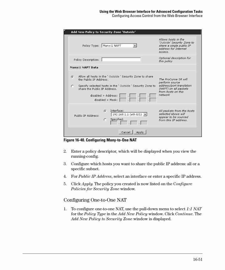
Figure 16-40. Configuring Many-to-One NAT
2. Enter a policy descriptor, which will be displayed when you view the running-config.
3. Configure which hosts you want to share the public IP address: all or a specific subnet.
4. For Public IP Address, select an interface or enter a specific IP address.
5. Click Apply. The policy you created is now listed on the Configure
Policies for Security Zone window.
Configuring One-to-One NAT
1. To configure one-to-one NAT, use the pull-down menu to select 1:1 NAT for the Policy Type in the Add New Policy window. Click Continue. The Add New Policy to Security Zone window is displayed.
16-51
Using the Web Browser Interface for Advanced Configuration TasksConfiguring Access Control from the Web Browser Interface
N o t e You must have more than one security zone configured on the router to use one-to-one NAT. If you do not, the screen shown below includes an alert in the Private Security Zone field.
Figure 16-41. Configuring One-to-One NAT
2. Enter a policy descriptor, which will be displayed when you view the running-config.
3. For Public IP Address, use the pull-down menu to select Any or one of the interfaces configured on the router. This setting determines the des-tination addresses the router will match for this NAT policy.
4. For Private IP Address, enter the address the device is using on the internal network.
5. From the Private Security Zone pull-down menu, select the security zone containing the private IP address that you entered in the previous step.
6. Click Apply. The policy that you created is now listed on the Configure
Policies for Security Zone window.
16-52
Using the Web Browser Interface for Advanced Configuration TasksConfiguring Access Control from the Web Browser Interface
Configuring Policies to Control Management Access to the ProCurve Secure Router
1. To create a policy that controls management access to the router, use the pull-down menu to select Admin Access for the Policy Type in the Add
New Policy window. Click Continue. The Add New Policy to Security
Zone window is displayed.
Figure 16-42. Policies for Controlling Management Access to the Router
2. For Public Address, select Any or specify a subnet. This setting deter-mines the source address—the hosts that you want to be able to access the router.
3. For Admin Access Type, select the types of access methods that you want to permit.
4. Click Apply. The policy that you created is now listed on the Configure
Policies for Security Zone window.
Customizing Your Policies
When you first start configuring policies, the Filter, Allow, Many:1 NAPT, and Port Forward options will help guide you through the process of setting control access on your router. As you become more experienced, however, you may want more flexibility in configuring policies.
16-53
Using the Web Browser Interface for Advanced Configuration TasksConfiguring Access Control from the Web Browser Interface
If the other options do not allow you to configure exactly the policy you need for your network, you should select the Advanced option for Policy Type. For example, if you want to configure one-to-one NAT and specify the public address, rather than selecting an interface and using the IP address assigned to it, you should create an Advanced policy.
1. In the Add New Policy window, use the Policy Type pull-down menu to select Advanced. Click Continue. The Add New Policy to Security Zone window is displayed.
Figure 16-43. Configuring Advanced Policies
2. For Policy Action, you can select one of the following:
• Allow—Select this option to allow certain types of traffic.
• Allow Reverse—Select this option to configure a policy that affects return traffic.
• Discard—Select this option to discard, or block, certain types of traffic.
• NAT—Select this option to configure either many-to-one NAT or one-to-one NAT.
16-54
Using the Web Browser Interface for Advanced Configuration TasksConfiguring Access Control from the Web Browser Interface
3. Enable Stateless Processing, if applicable.
4. For Destination Security Zone, select <Any Security Zone>, a particular security zone, or <Self-bound>. This setting determines the destination address of the traffic you want to select. The <Self-bound> option desig-nates the destination as the internal IP stack—the router itself.
5. If you select NAT as the Policy Action, the NAT options are enabled.
• Select Source with Overloading to configure many-to-one NAT.
• Select Destination to configure one-to-one NAT. You can then config-ure port translation.
6. Click Apply.
7. In the Add/Modify/Delete Policy Traffic Selectors section, click Add New
Traffic Selector. The Add New Custom Policy Entry window is displayed.
16-55
Using the Web Browser Interface for Advanced Configuration TasksConfiguring Access Control from the Web Browser Interface
Figure 16-44. Add New Custom Policy
8. For Filter Type, select Permit or Deny.
9. For Protocol, select any or a specific protocol.
10. If you select ICMP, then you can select an ICMP message type from a list of well known types.
11. Configure the Source Host/Network.
12. If you select UDP or TCP as the protocol, you can select a source port as well.
13. Configure the Destination Host/Network.
14. If you select UDP or TCP as the protocol, you can select a destination port.
15. Click Apply.
16-56
Using the Web Browser Interface for Advanced Configuration TasksConfiguring Access Control from the Web Browser Interface
Changing the Order of Policies
The policies you create for a security zone are listed and processed in the order shown on the Configure Policies for Security Zone window. (Access this window by clicking Security Zone <zonename> in the top navigation bar.) If you need to change the order in which policies are processed, use the green arrows to move a particular policy up or down in the list.
Figure 16-45. Changing the Order of Policies in a Security Zone
Assigning the Security Zone (the ACP) to an Interface
After you finish configuring the security zone (the ACP), you must assign it to an interface. The security zone will have no effect until you complete this final step.
1. In the navigation bar, select Security Zones under Firewall. The Assign
Interfaces to Security Zones window is displayed. The interfaces that are enabled on the ProCurve Secure Router are listed in this window.
2. Use the pull-down menu to select a security zone for each interface, and then click Assign.
3. If you need to edit the security zones you have created, you can access them from this window.
16-57
Using the Web Browser Interface for Advanced Configuration TasksConfiguring Quality of Service
Configuring Quality of Service
Your ProCurve Secure Router may route several types of traffic:
■ data, which can tolerate high latency and bursts, as well as be fragmented and reconstructed
■ real-time traffic, such as Voice of IP (VoIP), and interactive traffic, such as Telnet, which require low latency and low jitter
■ high priority traffic, which needs a certain amount of bandwidth and protection from being dropped
■ control plane traffic, which the router always serves no matter what queuing method the interface implements.
Quality of service (QoS) protocols allow routers to grant the appropriate type of service to various types of traffic.
The ProCurve Secure Router supports these QoS methods:
■ Weighted Fair Queuing (WFQ)—By default, the ProCurve Secure Router implements WFQ on interfaces with speeds of E1 or less. WFQ automat-ically divides traffic into conversation flows according to its source and destination and allocates bandwidth to these flows according to relative IP precedence.
■ Class Based Weighted Fair Queuing (CBWFQ)—With CBWFQ, you can manually define the classes and relative bandwidth for WFQ. On the ProCurve Secure Router, you can define up to four classes per interface and 16 total on the router. You can guarantee these classes up to 75% of an interface’s bandwidth.
■ Low Latency Queuing (LLQ)—Traffic placed in a low latency queue is always served first with a guaranteed amount of bandwidth. LLQ is usually the best solution for voice and other realtime traffic. An interface can implement both LLQ and CBWFQ or WFQ.
■ Packet marking—You may be able to negotiate better service from your service provider for packets marked with a specific ToS value in their IP headers. For example, the provider’s network could drop packets with a high priority value last. You can configure the ProCurve Secure Router to mark packets with the agreed-upon IP precedence or DiffServ value before forwarding them into the network.
Packets that the router marks with a higher IP precedence or DiffServ value also receive relatively more bandwidth with WFQ.
16-58
Using the Web Browser Interface for Advanced Configuration TasksConfiguring Quality of Service
You can configure WFQ, LLQ, and packet marking in the Web browser inter-face. Currently, you must configure CBWFQ in the CLI.
The QoS Wizard will help you set up a QoS policy for VoIP traffic.
N o t e Because the QoS Wizard writes over any QoS map entries already applied to the interface that you select to carry VoIP traffic, you should always use the wizard before configuring your own QoS policies.
You can also configure Frame Relay rate limiting and fragmentation. (Cur-rently, you must configure rate limiting for Ethernet interfaces from the CLI.) Rate limiting maintains QoS by preventing the Frame Relay interface from forwarding more traffic than a connection can handle. Fragmenting large data frames reduces serialization delay and allows the router to forward small, high priority traffic such as VoIP frames with a minimum of delay.
Configuring WFQ
By default, WFQ is enabled on all interfaces with speeds of E1 or less. These instructions assume that you have already configured the interface and that the connection is up. (To learn how to configure a logical interface, see “Configuring the Data Link Layer Protocol for E1, T1, and Serial Interfaces” on page 14-62 and “Configuring ADSL Interfaces” on page 14-78 of the Basic
Management and Configuration Guide.)
Follow these steps to enable or disable WFQ on PPP, Frame Relay, and HDLC interfaces:
1. Select IP Interfaces under Router/Bridge in the left navigation bar.
2. All logical interfaces on the router will display. Click the name of the interface for which you want to configure WFQ. (If the interface is not yet up, you must access it by selecting Physical Interfaces under System. Then select the logical interface.)
3. You will move to the interface’s Configuration window. Check the Weighted Fair Queuing box. If you want the interface to provide first-in, first-out (FIFO) service to all packets, uncheck the box.
4. Click Apply.
16-59
Using the Web Browser Interface for Advanced Configuration TasksConfiguring Quality of Service
Figure 16-46. Configuring WFQ on an Interface
To configure WFQ for ATM connections, follow these steps:
1. Depending on the type of encapsulation you are using for your ADSL connection, the ATM subinterface may or may not have an IP address. You can always access the ATM interface by selecting Physical Interfaces under System in the left navigation bar.
2. All physical interfaces and the logical interfaces to which they are bound display. Select the name of the ATM interface that includes the connection for which you want to configure WFQ.
3. The Configuration window for the interface displays. Select the ATM subinterface from the Configuring Virtual Circuits window.
4. The Configuration window for the interface displays. Check the Advanced Configuration box. The Advanced Configuration section displays.
5. Check the Fair-Queue box to enable WFQ. (Leave the box unchecked if you want the interface to use FIFO queuing.)
6. You can now configure WFQ parameters. (For other logical interfaces, you must configure these settings from the CLI.)
16-60
Using the Web Browser Interface for Advanced Configuration TasksConfiguring Quality of Service
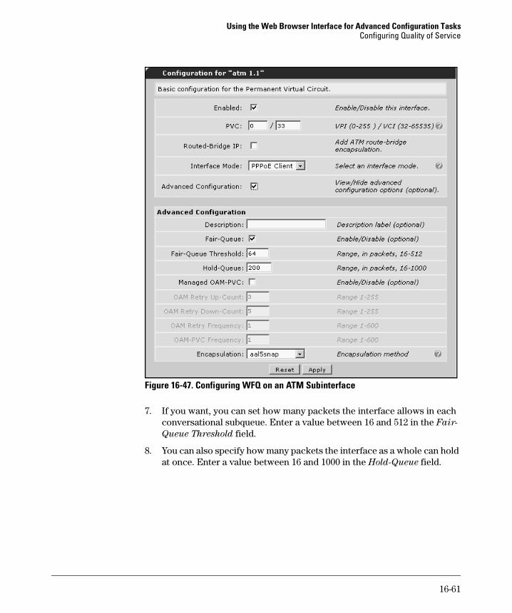
Figure 16-47. Configuring WFQ on an ATM Subinterface
7. If you want, you can set how many packets the interface allows in each conversational subqueue. Enter a value between 16 and 512 in the Fair-
Queue Threshold field.
8. You can also specify how many packets the interface as a whole can hold at once. Enter a value between 16 and 1000 in the Hold-Queue field.
16-61
Using the Web Browser Interface for Advanced Configuration TasksConfiguring Quality of Service
Configuring QoS for VoIP with the QoS Wizard
The QoS wizard guides you through the process of configuring QoS for VoIP applications.
C a u t i o n The QoS wizard erases any QoS maps already applied to the interface you select for VoIP traffic. You should therefore use the wizard before configuring your own QoS policies.
1. Select QoS Wizard under Router/Bridge in the left navigation bar. You will move to the wizard’s Welcome window. Click Next.
2. In the Select WAN Interface window, from the WAN Interface pull-down menu, select the interface used to carry VoIP traffic. Interfaces are listed by both physical and logical interface. The menu only includes activated interfaces that have been bound to a logical interface.
Figure 16-48. Selecting the Interface to Carry VoIP Traffic
3. Click Next.
16-62
Using the Web Browser Interface for Advanced Configuration TasksConfiguring Quality of Service
4. You will move to the VoIP Traffic Matching window, in which you specify how the router will identify VoIP packets:
a. The documentation for your VoIP application may include the UDP real-time protocol (RTP) port or ports to which traffic is sent. Select RTP and enter the range of ports in the Start Port and End Port fields. If this range includes odd ports, check the Enable Even and Odd Ports box.
b. If your VoIP application marks traffic with a ToS value, you can configure the router to select traffic with this value. The router can select traffic according to either DiffServ or IP precedence:– Select DSCP and enter the DiffServ value used by your VoIP
application. You can also accept the default value 46 (for expe-dited traffic).
– Select Precedence. Enter the IP precedence value used by your application or accept the default value 5 (for critical priority).
Figure 16-49. Defining VoIP Traffic
c. The router can also match traffic from a certain IP address or net-work. Select Source Address and enter the IP address and subnet mask in the Network and Mask fields.
5. Click Next.
16-63
Using the Web Browser Interface for Advanced Configuration TasksConfiguring Quality of Service
6. In the Configure Max Bandwidth window, enter the bandwidth for the queue in Kbps. This bandwidth is the maximum guaranteed. (When the network is not congested, VoIP traffic can burst past this rate.)
The window will display the maximum bandwidth available on the inter-face as the high end of the Limit. For example, in Figure 16-50, VoIP traffic will be carried over a single E1 carrier-line.
The wizard automatically specifies 60 percent of the interface’s access rate for the queue’s maximum guaranteed bandwidth. In the example in Figure 16-50, the default value is 1228 Kbps. You can accept this value or set your own.
Figure 16-50. Specifying the Maximum Bandwidth Guaranteed to a Queue
The documentation for your VoIP application may instruct you how to determine the necessary bandwidth. You can also see Chapter 8: Setting
Up Quality of Service for some general guidelines.
Click Next.
16-64
Using the Web Browser Interface for Advanced Configuration TasksConfiguring Quality of Service
7. You will now move to the DSCP Outbound Marking window. Because signaling traffic, as well as the VoIP packets themselves, must receive priority handling, you should mark signaling traffic with a ToS value. You can accept the default value 26 (for assured forwarding class 31) or enter any value between 0 and 63. However, you should enter a value for at least AF31. (See Table 16-2.)
The QoS wizard automatically configures the router to mark SIP signaling traffic with this value. If your VoIP devices do not use SIP, then you must configure the router to mark the signaling traffic from the CLI. See Chapter 8: Setting Up Quality of Service.
Table 16-2. Assured-Forwarding PHB
8. Click Next.
AF Class Drop Precedence DSCP DiffServ Value
AF1 low 001010 10
medium 001100 12
high 001110 14
AF2 low 010010 18
medium 010100 20
high 010110 22
AF3 low 011010 26
medium 011100 28
high 011110 30
AF4 low 100010 34
medium 100100 36
high 100110 38
16-65
Using the Web Browser Interface for Advanced Configuration TasksConfiguring Quality of Service
Figure 16-51. Sample QoS Configuration for VoIP Traffic
9. Review your settings in the Confirm window:
a. Use the Back button to reconfigure any incorrect settings. You can also click the name of a window in the left navigation bar. For example, you can select RTP Traffic to change how the router selects traffic for the queue.
b. If the settings are correct, click Finish.
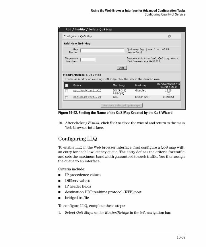
C a u t i o n Remember that these settings will overwrite any QoS policies already applied to the specified WAN interface. If you want to establish CBWFQ, another low latency queue, or packet marking on the interface, you must afterwards add entries to the map created by the QoS wizard. You can learn the name of this map by returning to the QoS Maps window and viewing the Modify/Delete a
QoS Map section of the Add/Modify/Delete QoS Map window. For example, in Figure 16-52 the name of the map is “ppp1QosWizard.”
16-66
Using the Web Browser Interface for Advanced Configuration TasksConfiguring Quality of Service
Figure 16-52. Finding the Name of the QoS Map Created by the QoS Wizard
10. After clicking Finish, click Exit to close the wizard and return to the main Web browser interface.
Configuring LLQ
To enable LLQ in the Web browser interface, first configure a QoS map with an entry for each low latency queue. The entry defines the criteria for traffic and sets the maximum bandwidth guaranteed to such traffic. You then assign the queue to an interface.
Criteria include:
■ IP precedence values
■ Diffserv values
■ IP header fields
■ destination UDP realtime protocol (RTP) port
■ bridged traffic
To configure LLQ, complete these steps:
1. Select QoS Maps under Router/Bridge in the left navigation bar.
16-67
Using the Web Browser Interface for Advanced Configuration TasksConfiguring Quality of Service
2. Enter a new QoS map entry in the Add New QoS Map section of the Modify/Delete QoS Maps window. Enter the name in the Map Name field and the sequence number in the Sequence Number field. You will apply all QoS map entries with the same name to the interface; the sequence number determines the order in which the router will process these entries.
Figure 16-53. Creating a QoS Map Entry
N o t e Remember that if you want to establish the queue to an interface for which you have already configured a map using the QoS wizard, you must enter the name of that map. You can find this name in the Modify/Delete a QoS Map section. (See, for example, Figure 16-52 on page 16-67.)
3. You will move to the QoS Map Setup for “<name>” window. Select the criteria for the queue in the Match Packets section:
a. To place RTP packets for certain applications in a queue, select IP
RTP. Then specify the range for the protocol ports by entering values in the Start Port and End Port fields. By default, the map only matches even ports. To match all ports, click the Enable Even and Odd Ports box. Figure 16-54 shows a map that matches traffic to even ports from 16,384 to 32,767— typical destination ports for real-time protocols.
b. To place packets in a queue according to their DiffServ value, select DSCP and enter a value between 0 and 63.
16-68
Using the Web Browser Interface for Advanced Configuration TasksConfiguring Quality of Service
Figure 16-54. Configuring Criteria for a QoS Map
c. To select packets according to their IP precedence value, select Precedence and enter a value between 0 and 7.
d. If the router has any access control lists (ACLs) in its system, you can choose one of these lists from the List pull-down menu. All packets selected by the list will be placed in the low latency queue.
e. To place bridged packets in a queue, select Bridged.
f. NetBIOS Extended User Interface (NetBEUI) allows hosts to commu-nicate within the LAN. To place only NetBEUI bridged packets in the queue, select NetBEUI.
16-69
Using the Web Browser Interface for Advanced Configuration TasksConfiguring Quality of Service
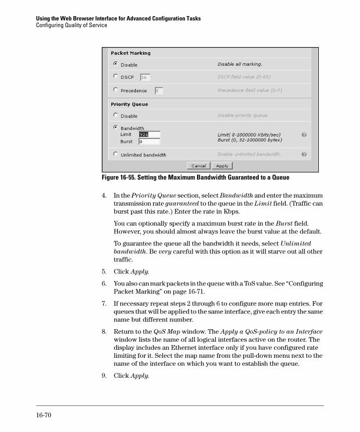
Figure 16-55. Setting the Maximum Bandwidth Guaranteed to a Queue
4. In the Priority Queue section, select Bandwidth and enter the maximum transmission rate guaranteed to the queue in the Limit field. (Traffic can burst past this rate.) Enter the rate in Kbps.
You can optionally specify a maximum burst rate in the Burst field. However, you should almost always leave the burst value at the default.
To guarantee the queue all the bandwidth it needs, select Unlimited
bandwidth. Be very careful with this option as it will starve out all other traffic.
5. Click Apply.
6. You also can mark packets in the queue with a ToS value. See “Configuring Packet Marking” on page 16-71.
7. If necessary repeat steps 2 through 6 to configure more map entries. For queues that will be applied to the same interface, give each entry the same name but different number.
8. Return to the QoS Map window. The Apply a QoS-policy to an Interface window lists the name of all logical interfaces active on the router. The display includes an Ethernet interface only if you have configured rate limiting for it. Select the map name from the pull-down menu next to the name of the interface on which you want to establish the queue.
9. Click Apply.
16-70
Using the Web Browser Interface for Advanced Configuration TasksConfiguring Quality of Service
Configuring Packet Marking
You can also use the Web browser interface to configure the router to mark packets with a ToS value. First configure a QoS map with an entry for each set of traffic you wish to mark. Then assign the QoS map to an interface.
1. Select QoS Maps under Router/Bridge in the left navigation bar.
2. Enter a new QoS map entry in the Add New QoS Map section of the Modify/Delete QoS Maps window. Enter the name in the Map Name field and the sequence number in the Sequence Number field. You will apply all QoS map entries with the same name to the interface; the sequence number determines the order in which the router will process these entries.
N o t e Remember that if you want to establish the queue to an interface for which you have already configured a map using the QoS wizard, you must enter the name of that map. See Figure 16-52.
3. Select the criteria for marked packets:
a. You can mark packets associated with specific real-time applications, such as video streams or VoIP packets. First select IP RTP. Then specify the range for the UDP destination ports by entering values in the Start Port and End Port fields. To match all ports in the range, rather than only even ones, click the Enable Even and Odd Ports box.
b. To change the ToS value of already-marked packets, select either DSCP for DiffServ or Precedence for IP precedence. Then enter the original ToS value in the corresponding field.
c. If the router has any access control lists (ACLs) in its system, you can choose one of these lists from the List pull-down menu. The router will mark all packets selected by the list.
d. To mark bridged packets, select Bridged.
e. NetBIOS Extended User Interface (NetBEUI) allows hosts to commu-nicate within the LAN. To mark only NetBEUI bridged packets with the ToS value, select NetBEUI.
16-71
Using the Web Browser Interface for Advanced Configuration TasksConfiguring Quality of Service
Figure 16-56. Marking Packets with a ToS Value
4. Move to the Packet Marking section. Enter the value with which the router should mark packets:
a. Select DSCP to enter a DiffServ value between 0 and 63.
b. Select Precedence to enter an IP precedence value between 0 and 7.
5. Only set a maximum bandwidth if you want to place the marked traffic in a low latency queue. See “Configuring LLQ” on page 16-67. If you want the QoS map entry only to mark packets select Disable under Priority Queue (see Figure 16-56).
6. Click Apply.
7. If necessary, repeat steps 2 through 6 to configure more map entries. For each set of traffic to be marked on the same interface, give the entry the same name but a different number. The router processes map entries in order starting with the lowest. (You can also apply LLQ to the same interface by configuring new map entries with the same name.)
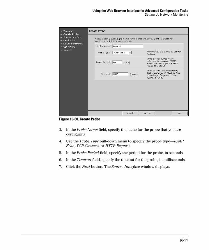
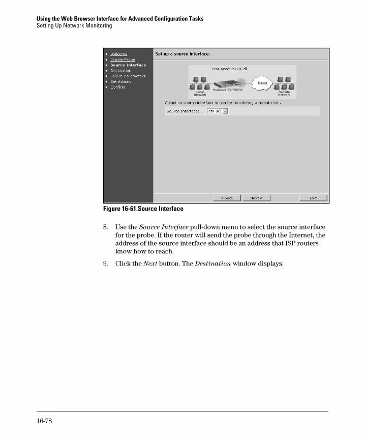
16-72
Using the Web Browser Interface for Advanced Configuration TasksConfiguring Quality of Service
Figure 16-57. Applying a QoS Policy to an Interface
8. Return to the QoS Map window. The Apply a QoS-policy to an Interface window lists the name of all logical interfaces active on the router. The display includes an Ethernet interface only if you have configured rate limiting for it. Select the map name from the pull-down menu next to the name of the interface that should mark packets.
9. Click Apply.
Configuring Frame Relay Fragmentation and Rate Limiting
These instructions assume that you have already configured the Frame Relay interface and PVCs. (See “Configure Frame Relay as the Data Link Layer Protocol” on page 14-68 of the Basic Management and Configuration Guide.) Follow these steps to configure fragmentation and rate limiting for a PVC:
1. Access the Frame Relay subinterface for the PVC for which you want to limit the rate.
a. Click IP Interfaces under Router/Bridge in the navigation bar. Select the Frame Relay subinterface.
b. If this interface does not have an IP address, then you must instead select Physical Interfaces under System. Then choose the Frame Relay interface associated with the PVC. You can then select the subinterface from the Configured Permanent Virtual Circuits window.
c. The Configuration window for the Frame Relay subinterface displays.
2. The router fragments any packet larger than the fragmentation threshold. Set the threshold in bytes in the Fragment field.
16-73
Using the Web Browser Interface for Advanced Configuration TasksConfiguring Quality of Service
N o t e If this Frame Relay PVC will carry VoIP traffic, take care to set the fragmen-tation threshold above the size of VoIP packets.
3. The committed burst rate determines the rate at which the Frame Relay interface can forward traffic when the network is congested. You should set the committed burst rate to equal the committed information rate (CIR) that you have negotiated with your service provider. Enter the rate in bps in the BC field.
4. The excessive burst rate determines the maximum rate at which the Frame Relay subinterface can ever forward traffic. Some service provid-ers allow you to burst up to the interface’s transmission rate. Others specify an excessive information rate (EIR). Consult your service level agreement (SLA). The value you enter in the BE field is the rate over the committed burst rate at which the interface can transmit data. In other words, the BC plus the BE equals the total maximum bandwidth available on the rate limited PVC.
5. Click Apply.
Figure 16-58. Rate Limiting a Frame Relay PVC
16-74
Using the Web Browser Interface for Advanced Configuration TasksSetting Up Network Monitoring
Setting Up Network Monitoring
Network monitoring serves two functions:
■ It tests and controls static and Dynamic Host Configuration Protocol (DHCP) routes.
■ It tests network performance, logging when performance falls below a certain level.
Network monitoring relies on two connected mechanisms:
■ Network monitor probes—A probe collects the information by which a route or a network server is tested. A probe can consist of packets as simple as ICMP echo packets (pings) or as complex as HTTP requests for particular information.
■ Network monitor tracks—A track uses probes to test routes or remote servers, with the goal of removing failed routes and logging poor perfor-mance.
You can use the settings in the Network Monitoring section of the Web browser interface to configure and enable network monitor probes and tracks.
For more information about network monitoring, see Chapter 9: Network
Monitoring.
Network Monitor Wizard
The Network Monitor Configuration wizard guides you through the configu-ration of network monitoring probes and tracks. It hides some of the config-uration from you by automatically configuring tracks and associating tracks with the correct probe and routes. The wizard also automatically configures PBR for probe traffic.
You must identify:
■ the probe name
■ the probe type—ICMP echo, TCP connect, or HTTP request
■ the probe period—how often the probe runs a test (by sending a packet out)
■ the probe’s source interface
■ the probe’s destination (and destination port for TCP connect and HTTP request probes)
16-75
Using the Web Browser Interface for Advanced Configuration TasksSetting Up Network Monitoring
■ the probe’s failure mode—consecutive failures, rate of failure, or none
■ the actions performed when the probe fails
To use the network monitor wizard to configure network monitoring:
1. Select Monitor Wizard under Network Monitoring in the left navigation bar. The Welcome window displays.
Figure 16-59. Welcome
2. Click the Next button. The Create Probe window displays.
16-76
Using the Web Browser Interface for Advanced Configuration TasksSetting Up Network Monitoring
Figure 16-60. Create Probe
3. In the Probe Name field, specify the name for the probe that you are configuring.
4. Use the Probe Type pull-down menu to specify the probe type—ICMP
Echo, TCP Connect, or HTTP Request.
5. In the Probe Period field, specify the period for the probe, in seconds.
6. In the Timeout field, specify the timeout for the probe, in milliseconds.
7. Click the Next button. The Source Interface window displays.
16-77
Using the Web Browser Interface for Advanced Configuration TasksSetting Up Network Monitoring
Figure 16-61.Source Interface
8. Use the Source Interface pull-down menu to select the source interface for the probe. If the router will send the probe through the Internet, the address of the source interface should be an address that ISP routers know how to reach.
9. Click the Next button. The Destination window displays.
16-78
Using the Web Browser Interface for Advanced Configuration TasksSetting Up Network Monitoring
Figure 16-62.Destination
10. In the Destination field, specify the IP address or hostname for a device at the destination that you want to monitor.
11. In the Destination Port field, specify the port for the service or application being monitored.
• For TCP connect probes, see Table 9-1 in Chapter 9: Network Moni-
toring for a list of ports for common TCP applications.
• For HTTP request probes, the default port is 80. If your server uses a different port, you can specify that port instead.
• For ICMP echo probes, the Destination Port field does not appear.
12. Click the Next button. If you are configuring an HTTP request probe, the HTTP Probe Details window displays. (If you are not configuring an HTTP request probe, the Set Up Failure Mode window displays; skip to step 15.)
16-79
Using the Web Browser Interface for Advanced Configuration TasksSetting Up Network Monitoring
Figure 16-63. HTTP Probe Details
13. Use the Request Type pull-down menu to select the type for the probe—HTTP Get, HTTP Head, or HTTP Raw. An HTTP Get probe sends a standard HTTP request for a Web page. An HTTP Head probe sends a similar request, but asks the Web server to return only the packet header rather than the entire Web page.
If you select the HTTP Raw type, you must configure the request. A text box appears in which you can type the series of HTTP commands that the ProCurve Secure Router places in the data portion of the probe packet. See Chapter 9: Network Monitoring for more information on raw strings.
14. Click the Next button. The Failure Parameters window displays.
16-80
Using the Web Browser Interface for Advanced Configuration TasksSetting Up Network Monitoring
Figure 16-64. Failure Parameters
15. Select the failure mode and settings.
• For the consecutive failures mode, specify the number of consecutive test failures to allow before declaring failure.
• For the rate of failure mode, specify the number of failures allowed within a set of tests. Specify the allowed number of failures in the Number of failures (x) field and the size of the set of tests in the Total
number of tests (y) field.
16. Click the Next button. The Set Actions window displays.
16-81
Using the Web Browser Interface for Advanced Configuration TasksSetting Up Network Monitoring
Figure 16-65. Set Actions
17. Select the action to take when the probe reports failure. For the Override
Static Route option, specify either NextHop IP (and specify the next hop address for the route) or NextHop Interface (and specify the forwarding interface for the route). If the forwarding interface is an Ethernet inter-face, you should select the NextHop IP option.
The Network Monitor Configuration Wizard creates a monitored default route through the interface or next-hop IP address specified.
18. Click the Next button. The Confirm window displays.
16-82
Using the Web Browser Interface for Advanced Configuration TasksSetting Up Network Monitoring
Figure 16-66. Confirm
19. Review the settings on the screen, and then click the Finish button to close the wizard and apply your network monitoring settings.
16-83
Using the Web Browser Interface for Advanced Configuration TasksSetting Up Network Monitoring
Creating a Network Monitor Probe
You can also create or modify probes manually. To create a probe:
1. Select General Monitor under Network Monitoring in the left navigation bar.
Figure 16-67. Create Probes
2. In the Probe Name field, enter the probe name.
3. Use the Type pull-down menu to specify the probe type—ICMP Echo, TCP
Connect, or HTTP Request.
4. Click the Create button to create the probe.
If you want to modify the configuration of a probe that you configured through the Wizard, select the probe from the table at the bottom of the Create probes section.
In either case, the screen shown in Figure 16-68 displays.
16-84
Using the Web Browser Interface for Advanced Configuration TasksSetting Up Network Monitoring
Figure 16-68. Probe Configuration (ICMP Probe Type Shown)
5. Click the Enable box to enable the probe.
6. In the Probe Period field, specify the period for the probe, in seconds.
7. In the Timeout field, specify the timeout for the probe, in milliseconds.
8. Under Tolerance, use the Mode pull-down menu to specify the tolerance for the probe:
• Consecutive Failures—use the Number of Failures pull-down menu to specify the number of consecutive test failures to allow before declaring failure.
• Failures per Set—use the Failure per Test and Test Size pull-down menus to specify the number of failures allowed within a certain number of tests before declaring failure.
9. In the Destination hostname field, specify the IP address or hostname for the destination that you want to monitor.
16-85
Using the Web Browser Interface for Advanced Configuration TasksSetting Up Network Monitoring
10. In the Destination Port field, specify the port for the service or application being monitored.
• For TCP connect probes, see Table 9-1 in Chapter 9: Network Moni-
toring for a list of ports for common TCP applications.
• For HTTP request probes, the default port is 80. If your server uses a different port, you can specify that port instead.
• For ICMP echo probes, the Destination Port field does not appear.
11. In the Source IP Address field, you can manually specify a probe’s source address.
If you leave this field empty, the router uses the probe’s forwarding interface as the source address. Leaving the field empty is often a good idea because the probe requires a valid address on one of the router’s local interfaces in order to function properly. When you manually specify a probe’s source address, you risk a probe malfunction if the local interface address is changed later.
12. In the Source Port field (which appears only for TCP connect and HTTP request probe types), you can also specify the source port.
13. For the ICMP echo probe type, you can specify:
• Data Size—the length of the ICMP packet
• Data Pattern—the hexadecimal pattern for the ICMP packet
14. For the HTTP request probe type, you can specify:
• Request Type—get, head, or raw
• Absolute Path—an alternative to the default / (forward slash)
15. Click the Apply button to save the probe configuration.
When you create a probe manually, you must configure a track with which to associate the probe.
Creating a Network Monitor Track
You can also create tracks manually or modify existing tracks.
1. Select General Monitor under Network Monitoring in the left navigation bar.
16-86
Using the Web Browser Interface for Advanced Configuration TasksSetting Up Network Monitoring
Figure 16-69. Create Tracks
2. In the Track Name field, enter the track name.
3. Click the Create button to create the track.
To modify an existing track, select the track from the table at the bottom of the Create Tracks section.
Figure 16-70. Track Configuration
4. Click the Enable box to enable the track.
5. In the Dampening Interval field, specify the dampening interval, in seconds. This interval delays the track changing state in response to its probes changing state.
16-87
Using the Web Browser Interface for Advanced Configuration TasksSetting Up Network Monitoring
6. Under Set Test Probes, use the Probe1 pull-down menu to select the probe associated with the track. If you will be using two probes, use the Probe2 pull-down menu to select the second probe.
7. If you are using two probes, use the Logical Operator pull-down menu to select how the probes should be evaluated logically:
• and to pass the track only when both probes pass
• or to pass the track when either probe passes).
8. Click the Apply button to save the track configuration.
If you have created the track manually, you must take a series of steps that the Network Monitor Configuration Wizard would have automatically per-formed for you:
1. Associate the track with the correct route. See “Routing” on page 14-117 in the Basic Management and Configuration Guide, Chapter 14: Using the
Web Browser Interface for Basic Configuration Tasks.
2. Configure PBR for the probe traffic, which you must complete from the CLI. See “Implementing PBR to Route Probe Traffic” on page 9-34 in Chapter 9: Network Monitoring.
If you do not want the track to take any action, you do not have to complete these steps.
16-88
Using the Web Browser Interface for Advanced Configuration TasksSetting Up Virtual Private Networks
Setting Up Virtual Private Networks
A virtual private network (VPN) establishes a secure, private connection between two peers over an insecure environment such as the Internet. On the ProCurve Secure Router, the optional IPSec module supports VPNs.
In this chapter, you will focus on using the VPN wizard to set up the VPN. If you want to learn about IPSec so that you can configure a more complex VPN with customized settings, see the overview in Chapter 10: Virtual Private
Networks.
The Web browser interface simplifies VPN configuration. The VPN wizard prompts you to enter information about your network such as the ID of the local and remote peer and the networks included in the VPN. It then uses this information to configure the VPN for you.
You can also use advanced options to alter security parameters according to your organization’s policies.
To access the VPN wizard, select VPN Wizard under VPN in the navigation bar.
VPN Wizard
The VPN wizard guides you through the configuration of a VPN. It manages the configuration of the necessary ACLs, IKE policies, and crypto map entries based on the information you give it. You must identify:
■ the local router’s VPN interface
■ whether the VPN peer is static, dynamic, or mobile
■ IKE mode config settings (for client-to-site VPNs only)
■ remote ID—domain name, email address, IP address, any
■ local ID—domain name, email address, IP address
When you start the VPN wizard, a Welcome screen displays. Click Next.
16-89
Using the Web Browser Interface for Advanced Configuration TasksSetting Up Virtual Private Networks
You must then choose between typical or custom setup. Custom setup is exactly like typical setup except that it includes two extra windows in which you can alter IKE and IPSec security parameters. Select the type of setup and click Next.
VPN Peer Name
You should enter the domain name for the device to which the local router will connect. This name identifies the VPN peer, and, depending on how you configure the peer’s remote ID, IKE may use this name when authenticating the peer.
N o t e If you prefer, you can enter any alphanumeric name that identifies the con-nection to you. You can also use the wizard to help build the initial VPN and then modify the configuration in the CLI for more meaningful naming.
Click Next.
Public Interface
The wizard will first prompt you for the local router’s public interface, or the interface through which you connect to the VPN peer. Typically, this is the WAN interface that connects to the Internet. Select this interface from the pull-down menu.
N o t e The pull-down menu only includes activated interfaces with an IP address.
Peer Type
Check the circle to indicate whether the peer is static, dynamic, or mobile.
16-90
Using the Web Browser Interface for Advanced Configuration TasksSetting Up Virtual Private Networks
Figure 16-71. Specifying the VPN Peer Type
Site-to-Site Configuration. You must inform the wizard whether the remote gateway device has a static or dynamic IP address. If the remote device has a static address, select the Static Peer circle and enter the peer’s public IP address. (This is the address through which the peer connects to you).
You must select the Dynamic peer circle if the remote device receives a dynamic address—for example, from a DHCP server or a service provider. The VPN wizard will prompt you to identify the peer (for example, by its domain name) in a later window.
N o t e You cannot initiate IKE with a dynamic peer. You can only respond to the peer’s request to open a VPN tunnel. For this reason, at least one of the routers in the VPN connection must have a static address.
Client-to-Site Configuration. You should select the Mobile Peer circle.
16-91
Using the Web Browser Interface for Advanced Configuration TasksSetting Up Virtual Private Networks
Mobile VPN Peer Settings (Client-to-site VPN Only)
In a client-to-site VPN, mobile users may tunnel into the VPN using many different private connections. Therefore, they may have IP addresses in many different networks. In order to allow a mobile user to access the VPN, the ProCurve Secure Router must first assign it an IP address on a local private network.
Figure 16-72. Configuring an IKE Mode Config Pool for Mobile VPN Peers
Enter the network from which the router should assign remote clients addresses in the IP Address fields.
N o t e The private network for remote users should be different from that for local users.
You can optionally configure IP addresses for up to two DNS servers and up to two WINS servers. These servers will resolve hostnames to IP addresses for the clients. Enter the address for the server in the field to the right of its name. For example, in Figure 16-72, the administrator has entered the address of a local DNS and WINS server in the Primary DNS Server and Primary
WINS Server fields.
16-92
Using the Web Browser Interface for Advanced Configuration TasksSetting Up Virtual Private Networks
(The configurations for mobile users are sometimes called an IKE mode config pool.)
Extended Authentication (Client-to-site VPN Only)
If you select the mobile option, the wizard will take you to the Extended
Authentication window. Extended authentication (Xauth) requires remote users to authenticate themselves individually in between negotiating the IKE SA and the IPSec SA. Xauth is particularly important when you use preshared keys for a client-to-site VPN. The same preshared key authenticates all remote users, but the more people with whom you share a secret, the more vulnerable the secret becomes. Xauth adds another layer of security by authenticating each user with an individual username and password.
If you choose to use Xauth, the ProCurve Secure Router matches the mobile user’s username and password against one of two databases:
■ the router’s local database
■ a RADIUS database
Figure 16-73. Enabling Xauth
Select the database you wish to use from the pull-down menu. If you do not want to use Xauth, leave the pull-down menu at the Disable Xauth option.
16-93
Using the Web Browser Interface for Advanced Configuration TasksSetting Up Virtual Private Networks
Remote Network
If you are configuring a site-to-site VPN, then you must specify the remote networks that are part of the VPN. Enter the IP address and subnet mask for the remote network.
Local Network
The VPN wizard allows you to select the address range for local VPN networks from a pull-down menu. This menu includes all networks configured on active interfaces.
Figure 16-74. Specifying the Local VPN Network
If you need to allow a range of subnets access to the VPN, some of which are not directly connected to the router, you should leave the Use Network from pull-down menu at <Specified>. Then enter the IP address and subnet mask for the range of subnets in the Local Subnet and Local Subnet Mask fields.
Click Next.
16-94
Using the Web Browser Interface for Advanced Configuration TasksSetting Up Virtual Private Networks
Authentication Type
Select whether IKE should authenticate peers using preshared keys or digital certificates. If you choose preshared keys, you must then enter the key in the Preshared Secret field.
If you are using digital certificates, you should select the standard. Click the circle for either RSA Certificate or DSS Certificate.
Figure 16-75. Configuring the Authentication Method
Remote ID
By default, the VPN wizard identifies the peer by its domain name. It fills in the Remote ID Value field with the name you gave to the VPN peer. If you did not enter this name, you should now change the entry in this field to the remote device’s domain name.
You can also identify the peer by its email address. Select Email address from the Remote ID Type pull-down menu and enter the address. (The email address is purely for identification; it does not have to be valid.)
For a client-to-site VPN (mobile peers), you can choose Allow Any Remote ID from the Remote ID Type pull-down menu.
16-95
Using the Web Browser Interface for Advanced Configuration TasksSetting Up Virtual Private Networks
Local ID
You can configure the local router to identify itself to the peer with:
■ a domain name
■ an email address
■ an IP address
Select one of these options from the Local ID Type pull-down menu. By default, the VPN wizard uses Domain Name as the Local ID Type and the hostname configured on the local router as the Local ID Value.
If you choose an IP address for the Local ID Type, the Local ID Value is the address for the interface through which the router connects to the VPN peer.
IKE Settings (Custom Setup Only)
In this window, you can specify in which modes the local router can initiate and respond to IKE. Main mode is more secure than aggressive mode because it protects the peers’ authentication information. However, aggressive mode is less taxing on the processor.
Select either Main Mode or Aggressive Mode from the Initiate Using pull-down menu to specify the mode in which the router initiates IKE.
When the peer initiates IKE, the local router must be able to respond in the same mode. You can configure the router to respond to either main or aggressive mode, or both. Select the desired setting from the Respond Using pull-down menu.
16-96
Using the Web Browser Interface for Advanced Configuration TasksSetting Up Virtual Private Networks
Figure 16-76. Establishing Security Parameters for the IKE SA
You can also alter the security parameters IKE proposes for the IKE SA, including:
■ hash algorithm
■ encryption algorithm
■ Diffie-Hellman key group
■ IKE SA lifetime
Select the desired setting from the pull-down menu for each parameter. Table 16-3 displays settings available for these parameters. Specify how long the router should keep the SA open by entering a value in seconds in the IKE SA Lifetime field. See Chapter 10: Virtual Private Networks for more information on these security parameters.
16-97
Using the Web Browser Interface for Advanced Configuration TasksSetting Up Virtual Private Networks
Table 16-3. Settings for IKE Security Parameters
C a u t i o n Take care when altering default security settings. Security parameters for both the IKE and the IPSec SA must match those proposed by the peer.
authentication type • preshared key• DSS certificate• RSA certificate
DH group • 1• 2
lifetime 60 to 86,400 seconds (1 minute to 1 day)
16-98
Using the Web Browser Interface for Advanced Configuration TasksSetting Up Virtual Private Networks
Figure 16-77. Establishing Security Parameters for the IPSec SA
IPSec Settings (Custom Setup Only)
In this window, you can alter the settings IKE proposes for the IKE SA, including:
■ Encryption/hash algorithm—You can select any combination of ESP encryption and/or hash algorithm, AH hash algorithm, or AH hash and ESP encryption and/or hash algorithm from the Encryption Algorithm pull-down menu.
■ PFS Diffie-Hellman group—If you specify a perfect forward secrecy (PFS) group, IKE uses the Diffie-Hellman protocol to generate entirely new keys for the IPSec SA. You can select group 1 or group 2. By default, IKE does not use a PFS. (See Chapter 10: Virtual Private Networks for more information on PFS.)
■ IPSec SA lifetime—You can specify a setting in kilobytes, seconds, or both. The router terminates the tunnel when the first limit is reached.
Table 16-4 displays settings available for these parameters.
C a u t i o n Take care when altering default security settings. Security parameters for both the IKE and the IPSec SA must match those proposed by the peer.
16-99
Using the Web Browser Interface for Advanced Configuration TasksSetting Up Virtual Private Networks
Table 16-4. Settings for IPSec Security Parameters
Confirm Settings
The Confirm Settings window displays the configurations for the remote and local peer ID and VPN networks, as well as the security parameters for the IKE and IPSec SAs. (If you selected Typical setup, the security parameters will be set at their defaults.)
Parameter Setting
hash and encryption algorithms • AH—one hash algorithm:– MD5– SHA
• ESP—one encryption algorithm or any combination of one encryption and one hash algorithm:Encryption algorithms:– DES– 3DES– AES (128-bit)– AES (192-bit)– AES (256-bit)– NullHash algorithms:– MD5– SHA
• AH and ESP– one AH hash algorithm and one ESP encryption
algorithm– one AH hash algorithm and any combination of one
ESP encryption algorithm and one ESP hash algorithm
PFS • 1• 2
IPSec SA lifetime • 120 to 86,400 seconds (2 minutes to 24 hours)• 2560 to 536,870,912 kilobytes
16-100
Using the Web Browser Interface for Advanced Configuration TasksSetting Up Virtual Private Networks
Figure 16-78. Reviewing VPN Settings
Review the information and ensure that it matches your network topology. Also verify that the default security settings are adequate to enforce your organization’s security policies.
If necessary, use the Back button in the interface window to navigate to the correct window and alter configurations. You can also select the name of a window in the left navigation bar. For example, select Remote Network to change the address for the remote VPN network.
N o t e If you used Typical setup, but you want to change the security parameters, you must proceed to the VPN Peers window.
Click Finish to apply the VPN. A window displays telling you that the VPN policy has been applied. Click Exit to return to the main Web browser
interface.
You should now be at the VPN Peers window.
16-101
Using the Web Browser Interface for Advanced Configuration TasksSetting Up Virtual Private Networks
VPN Peers
The VPN Peers window allows you to add new VPN connections. You can also alter IKE and IPSec SA parameters. The window should display when you close the VPN wizard. You can also access the window by selecting VPN Peers under VPN in the left navigation bar.
Adding a Second Remote Site to the VPN
The VPN wizard only allows you to configure a connection to a single VPN peer at a time. You can add a connection to another site (or to mobile clients) in two ways:
■ Run the VPN wizard again.
■ Select Create New VPN Peer in the second window of the Create VPN
Peers window.
When you use the second option, the interface allows you to select a policy from a pull-down menu on which to base the new policy. This option saves you time by automatically importing all the configurations from the policy you select.
16-102
Using the Web Browser Interface for Advanced Configuration TasksSetting Up Virtual Private Networks
Figure 16-79. Adding VPN Peers
The interface then takes you to a new window with several sub-windows that guide you through the process of adding the site.
Often you will want to use the same security settings for each connection. In this case, you only need to alter the configurations for the peer’s IP address, remote ID, preshared key, and remote network.
16-103
Using the Web Browser Interface for Advanced Configuration TasksSetting Up Virtual Private Networks
Figure 16-80. Configuring a Second VPN Site
Site-to-Site Configuration. Complete the following steps:
1. In the Step 1 of 4: VPN Peer Configuration for “<VPN mapname>”
window, enter the new peer’s domain name (or another name indicative of the connection).
2. For the Peer Type, select whether the peer is Static Addressed or Dynam-
ically Addressed.
16-104
Using the Web Browser Interface for Advanced Configuration TasksSetting Up Virtual Private Networks
Figure 16-81. Configuring IKE for a VPN Connection
3. Now move to the IKE Configuration section of the VPN Peer Configu-
ration for “<VPN mapname>” window.
4. If you have selected Static Addressed, the wizard will display a section for the Peer IP Address. You should enter the peer’s public IP address. This section will not display if you selected Dynamically Addressed.
5. Select the Remote ID for the new VPN peer from the pull-down menu. As well as the options for ID type discussed when configuring a connection with the VPN wizard, you can select IP Address or ASN1 DN.
You should only select IP Address if the peer has a static address. Enter the same address that you entered for the Peer IP Address.
16-105
Using the Web Browser Interface for Advanced Configuration TasksSetting Up Virtual Private Networks
You can use the ASN1 DN option when you are using digital certificates as the IKE authentication method. You must enter the fields exactly as they are in the certificate. You can use the wildcard character (*) to allow any value for some of the fields.
6. If you are using preshared keys, enter the key in the Preshared Key field.
7. If you have based the policy on a pre-existing policy and you want to use the same security settings and allow the same local networks, you can move to step 11. If you want to accept default settings, but you need to add a local network, move to step 10.
8. If you want to, you can change IPSec SA settings in the IPSec Configura-
tion section of the Step 1 of 4: VPN Peer Configuration for “<VPN
mapname>” window. Select settings for the following parameters from their pull-down menus:
• PFS group
• Encryption/hash algorithm—A pull-down menu provides all available combinations of algorithms. The window includes two pull-down menus, so you can specify up to two sets of algorithms.
• IPSec SA lifetime
For more information on these settings, see “IPSec Settings (Custom Setup Only)” on page 16-99.
9. You can alter the default security settings for the IKE SA in the Step 2 of 4: Add/Delete IKE attributes for “<VPN mapname>” window. Select set-tings for the following parameters from the pull-down menu for each:
• encryption/hash algorithm
• authentication method
• Diffie-Hellman key group
• IKE SA lifetime
For more information on these settings, see “IKE Settings (Custom Setup Only)” on page 16-96.
10. You add local networks to the VPN in the Step 3 of 4: Source Networks
Allowed to Connect Using “<VPN mapname>” window. Enter the IP address and subnet mask.
16-106
Using the Web Browser Interface for Advanced Configuration TasksSetting Up Virtual Private Networks
Figure 16-82. Adding Local VPN Networks
If you based the policy on a previous policy, the window already includes the local network(s) for that policy. If necessary, delete it.
11. Enter the IP address and subnet mask for the remote network in the Step 4 of 4: Destination Networks Allowed to Connect Using “<VPN
mapname>” window.
If you have based the policy on a previous policy, you can click the already configured network. The wizard will populate the fields above with the correct values. You can then edit the address as necessary. Click Add.
For example, you click the entry for remote IP subnet 192.168.2.0 255.255.255.0 displayed at the bottom of the window in Figure 16-83. The Web browser interface fills in the fields above as shown in Figure 16-83.
16-107
Using the Web Browser Interface for Advanced Configuration TasksSetting Up Virtual Private Networks
Figure 16-83. Selecting an Entry to Edit
You can then edit the entry to 192.168.3.0 as shown in Figure 16-84.
Figure 16-84. Creating the New Entry
The interface adds the new network, but also keeps the first. If you do not want to include this network, you must delete it by clicking the Delete button to the right of the entry for the remote network.
Client-to-Site Configuration. To add a mobile client to the VPN, you must complete these steps:
16-108
Using the Web Browser Interface for Advanced Configuration TasksSetting Up Virtual Private Networks
1. In the Step 1 of 4: VPN Peer Configuration for “<VPN mapname>”
window, enter a name for the connection to the clients.
2. Select Mobile Peer for the Peer Type. The interface adds a new step to the process, so the window will now be labelled Step 1 of 5.
3. If you are basing this connection on a previous connection and you want to keep the same security settings, or if you want to use the default settings, continue with step 6.
4. You can alter the security settings for the IPSec SA in the IPSec Configu-
ration section of the Step 1 of 4: VPN Peer Configuration for “<VPN
mapname>” window. Select settings for the following parameters from their pull-down menus:
• PFS group
• Encryption/hash algorithm—A pull-down menu provides all available combinations of algorithms. The window includes two pull-down menus, so you can specify up to two sets of algorithms.
• IPSec SA lifetime
For more information on these settings, see “IPSec Settings (Custom Setup Only)” on page 16-99.
5. You can alter the default security settings for the IKE SA in the Step 2 of 5: Add/Delete IKE attributes for “<VPN mapname>” window. Select set-tings for the following parameters from their pull-down menus:
• encryption/hash algorithm
• authentication method
• Diffie-Hellman key group
• IKE SA lifetime
Select the desired setting from the pull-down menu for each parameter. Enter the IKE SA lifetime in the Lifetime field in seconds.
For more information on these settings, see “IKE Settings (Custom Setup Only)” on page 16-96.
C a u t i o n Take care when altering default security settings. Security parameters for both the IKE and the IPSec SA must match those proposed by the peer.
6. Move to the Step 3 of 5: Remote IDs Allowed to Connect to “<VPN
mapname>” window. The router uses the remote ID to determine whether a peer can connect to the VPN and what policies the router should use when negotiating a VPN connection with that peer.
16-109
Using the Web Browser Interface for Advanced Configuration TasksSetting Up Virtual Private Networks
For the Remote ID Type, you can select IP Address, IP Subnet, Domain
Name, Email Address, Distinguished Name, or Match Any Remote ID. The interface labels the field below depending on the ID type that you select.
If you select IP Address, all VPN clients must use that exact IP address. (This remote ID type is not typical for a VPN connection to mobile users.) You can select IP Subnet instead to allow access to an entire range of addresses; this solution is best for mobile users in a private network, not for mobile users tunneling through their own Internet connections.
The email address is purely for identifying the client; it does not have to be valid. You can use the wildcard character (*) to match a range of addresses. For example, you could enter *@procurve.com to allow [email protected], [email protected], and so forth, remote access to the VPN.
Figure 16-85. Configuring the Remote ID for Mobile Peers
16-110
Using the Web Browser Interface for Advanced Configuration TasksSetting Up Virtual Private Networks
When your VPN uses digital certificates for authentication, you can select Distinguished Name. You must enter the fields exactly as they are in the certificate. You can use the wildcard character (*) to allow any value for some of the fields.
7. Click Add.
8. In the Step 4 of 5: Remote Addressing for X window, specify the addresses from a private network that IKE should assign to remote users.
Enter the first and last addresses in the range of IP addresses for remote users in the IP Address Range fields. You can also enter IP addresses for the DNS servers or WINS servers that should resolve local hostnames for remote users.
N o t e The private network for remote users should be different from that for local users.
Figure 16-86. Assigning IP Addresses to Remote VPN Users
16-111
Using the Web Browser Interface for Advanced Configuration TasksSetting Up Virtual Private Networks
N o t e You specify the first and the last address in a range when configuring addresses for remote users from this window. This configuration is different from that in the VPN wizard, where you specify the network IP address and subnet mask.
9. Move to the Step 5 of 5: Add/Modify/Delete Policy Entry window. Click the Add New VPN Selectors button.
Figure 16-87. Specifying the Local and Remote Networks for a Client-to-Site VPN
10. A new window displays, in which you can configure the VPN connection to include the network containing addresses for the remote client. Leave the Filter type at the default, permit, and the protocol at the default, any.
16-112
Using the Web Browser Interface for Advanced Configuration TasksSetting Up Virtual Private Networks
a. In the Source Data field, enter the IP address and subnet mask for the local network you want to include in the VPN.
b. In the Destination Data field, enter the IP address and subnet mask for the private network for remote users. For example, in Figure 16-87, the administrator has entered 192.168.100.0 255.255.255.0. This network includes the range of addresses for remote clients shown configured in Figure 16-86.
c. Click Add.
11. If you have based this connection on a previous one, you may need to delete a VPN selector. For example, the policy may permit traffic between two remote sites, but you only want to use this policy for mobile users. You can delete a VPN selector by clicking the Delete button to its right.
Configuring Advanced VPN Parameters
If you selected Typical setup in the VPN wizard, you were not able to alter the IKE SA and IPSec SA security parameters. However, you can tailor them as needed in the Advanced VPN Policies window.
N o t e You should typically use the Advanced VPN Policies window to simply alter security settings for a VPN or to add or delete networks from the VPN. If you want to establish a new VPN connection, you can complete all necessary steps by adding a VPN peer from the VPN Peers window.
Follow these steps:
1. Select VPN Peers under VPN in the left navigation bar.
2. In the third window, Advanced VPN Policies, click the Advanced VPN
Policies button.
You will move to a new window, from which you can configure IKE and IPSec policies.
Configuring IKE SA Parameters
Follow these steps:
1. The first window, Add/Modify/Delete IKE Policies, offers you several choices:
a. You can modify an already existing IKE policy. For example, you may have used the VPN wizard to establish a VPN connection. The wizard will have already created an IKE policy, which will be listed at the bottom of the window. Click the Name/ID of the policy.
16-113
Using the Web Browser Interface for Advanced Configuration TasksSetting Up Virtual Private Networks
b. You can create a new IKE policy based on the Secure Router OS default settings. In the Based on Policy pull-down menu, select Default, and then click the Add New Policy button.
c. You can also create a new IKE policy based on an already configured policy. The VPN wizard will import the settings for the configured policy into the new policy, and you can edit the settings that you want to change. In the Based on Policy pull-down menu, select the number of the base policy, and then click the Add New Policy button.
Figure 16-88. Adding or Modifying an IKE Policy
The IKE Policy “<policynumber>” window displays.
2. If you have created a new IKE policy, be sure to configure a different peer for the policy.
3. In the IKE Configuration for IKE Priority ID <number> window, you can specify the mode in which the router initiates and responds to IKE. Main mode is more secure than aggressive. The local router must initiate IKE in a mode to which the peer responds and vice versa. (For more information on IKE modes, see Chapter 10: Virtual Private Networks.)
Select the setting you want from the Initiate Mode and Respond Mode pull-down menus. If you do not know what the different modes entail, leave the settings at their defaults: Aggressive for the Initiate Mode and Any for the Respond Mode.
16-114
Using the Web Browser Interface for Advanced Configuration TasksSetting Up Virtual Private Networks
Figure 16-89. Configuring Advanced IKE Options
4. You can modify security parameters in the Add/Modify/Delete IKE
Attributes for Priority ID <policynumber> window. These parameters include:
• encryption/hash algorithm
• authentication method
• Diffie-Hellman key group
• IKE SA lifetime
Select the desired setting from the pull-down menu for each parameter. Enter the IKE SA lifetime in the Lifetime field in seconds. The local settings must match the peer’s settings. Table 16-5 displays settings that you can configure for the IKE policy.
16-115
Using the Web Browser Interface for Advanced Configuration TasksSetting Up Virtual Private Networks
Table 16-5. Settings for IKE Security Parameters
Configuring IPSec SA Parameters
You can also alter the IPSec SA parameters. These security settings are particularly important as they define the keys that secure all traffic sent over the VPN tunnel.
authentication type • preshared key• DSS certificate• RSA certificate
DH group • 1• 2
lifetime 60 to 86,400 seconds (1 minute to 1 day)
16-116
Using the Web Browser Interface for Advanced Configuration TasksSetting Up Virtual Private Networks
1. You should be in the Advanced VPN Policies window. Scroll to the Add/
Modify/Delete IPSec Policies window.
2. You have several choices:
a. You can modify an existing policy. You should select this option if you simply want to change the security parameters for a VPN connection. IPSec policies are listed by name and then number at the bottom of the window. Click the Name/ID of the policy that you want to modify.
b. You can create an entirely new IPSec policy. Unless you are configur-ing a VPN on a different WAN interface, this policy should have the same name as already established policies (for example, the wizard names policies “VPN”). The Secure Router OS uses this name to apply an entire group of IPSec policies to an interface. However, you should assign the new policy a different number from other policies.
Select the name of the policy from the pull-down menu in the Add
New IPSec Policy section. Then enter a number for the new policy in the Priority field.
c. You can create a new IPSec policy based on a pre-existing policy. Select the Copy option. Choose the base policy from the pull-down menu and enter a new number for the priority.
N o t e The Secure Router OS applies every policy with the same name to an interface. You can configure a different peer in each policy with a different priority number.
3. The IPSec Policy <mapname> Priority <number> window displays.
4. You can modify settings for security parameters in the IPSec Configura-
tion window. Select the setting that you want from the pull-down menu next to the parameter’s name. Parameters include:
• PFS Diffie-Hellman group• Encryption/hash algorithm—A pull-down menu provides all available
combinations of algorithms. The window includes two pull-down menus, so you can specify up to two sets of algorithms.
• IPSec SA lifetime
See “IPSec Settings (Custom Setup Only)” on page 16-99 for more infor-mation on configuring these settings. Table 16-6 displays settings that you can configure for the IPSec policy.
16-117
Using the Web Browser Interface for Advanced Configuration TasksSetting Up Virtual Private Networks
Table 16-6. Settings for IPSec Security Parameters
5. You can add or remove networks from the VPN in the Add/Modify/Delete
Policy Entries window. Click Add New VPN Selector.
6. Configure the filter to permit the new network(s):
a. Leave the Filter type at the default, permit, and the protocol at the default, any.
b. In the Source Data field, enter the IP address and subnet mask for the local network you want to include in the VPN.
c. In the Destination Data field, enter the IP address and subnet mask for the remote VPN network.
d. Click Add.
Parameter Setting
hash and encryption algorithms • AH—one hash algorithm:– MD5– SHA
• ESP—one encryption algorithm or any combination of one encryption and one hash algorithm:Encryption algorithms:– DES– 3DES– AES (128-bit)– AES (192-bit)– AES (256-bit)– NullHash algorithms:– MD5– SHA
• AH and ESP– One AH hash algorithm and one ESP encryption
algorithm– Or, one AH hash algorithm and any combination
of one ESP encryption algorithm and one ESP hash algorithm
PFS • 1• 2
IPSec SA lifetime • 120 to 86,400 seconds (2 minutes to 24 hours)• 2560 to 536,870,912 kilobytes
16-118
Using the Web Browser Interface for Advanced Configuration TasksSetting Up Virtual Private Networks
Enabling Xauth
Xauth allows IKE to request authentication information from remote users in between establishing the IKE SA and the IPSec SA. (This authentication information is different from the authentication method configured for IKE phase 1; it is individual to each user.) Xauth is typically used for increased security in client-to-site VPNs. Indeed, the VPN wizard will automatically prompt you to enable Xauth when you select mobile peers, as discussed in “Extended Authentication (Client-to-site VPN Only)” on page 16-93.
You can also use Xauth in a site-to-site VPN. Some gateway devices, including ProCurve Secure Routers, can act as Xauth hosts, which allows the local router to request authentication from the remote gateway device itself.
Figure 16-91. Enabling AAA from the Passwords Window
To enable Xauth:
1. Select Passwords under System in the left navigation bar.
2. In the Service Authentication window, click the AAA Mode Enabled box.
16-119
Using the Web Browser Interface for Advanced Configuration TasksSetting Up Virtual Private Networks
3. If the router will use its local database to authenticate the remote VPN peers, then you should check this list in the Add/Modify/Delete Users window above.
4. If IKE will refer to a RADIUS server for VPN peers’ passwords, you must configure the router to communicate with this server. See “Configuring Authentication Using a RADIUS Server” on page 14-36 of the Basic
Management and Configuration Guide.
5. Click Apply.
6. Select VPN Peers under VPN in the navigation bar.
7. Scroll to the Create VPN Peers section. In the Modify/View/Delete Peer
section, click the name of the peer that should require Xauth. The win-dows for the steps to configure this peer display.
8. Move to the IKE Configuration section of the Step 1 window.
Figure 16-92. Enabling Xauth
9. Choose the Xauth method from Xauth Enabled pull-down menu:
a. To use the router’s username and password database, select Local
Userlist.
b. To use a RADIUS server database, select Radius Server.
Adding Remote IDs
The remote ID list acts as a username database for the VPN. The ID type can be an IP address or network, domain name, email address, or ASN distin-guished name. If you are using preshared keys for authentication, you can associate a preshared key with the remote ID, much as you would a password with a username.
You should add an entry for each peer to which the router will make a VPN connection as you configure the connection. However, you can also add an entry in the VPN Peers window. You can also delete misconfigured entries.
16-120
Using the Web Browser Interface for Advanced Configuration TasksSetting Up Virtual Private Networks
Figure 16-93. Configuring the Remote ID List
1. Select VPN Peers under VPN in the left navigation bar.
2. Move to the Advanced VPN Policies window and click the Advanced VPN
Policies button.
3. Move to the Add/Modify VPN Remote IDs window. Click Add New Remote
ID.
4. Depending on how you want to identify the peer, select one of the following from the Remote ID Type pull-down menu:
• IP Address
• IP Subnet
• Domain Name
• Distinguished Name
• Email Address
• Match Any Remote ID
Remember that you can only use distinguished names when using a digital signature standard for IKE authentication. You should enter an IP address when using IKE main mode.
16-121
Using the Web Browser Interface for Advanced Configuration TasksSetting Up Virtual Private Networks
Figure 16-94. Adding a Remote ID
5. The field below is altered according to the ID type that you select. You enter the peer’s identification information in this field. For example, in Figure 16-94 the Remote ID Type is Domain Name, so the field becomes the Domain Name field. You can enter *.procurve.com to allow any device with a domain name ending in procurve.com to access the VPN.
6. If your VPN uses preshared keys for authentication, enter the key in the Preshared Key field.
7. If this remote ID is for mobile peers, you should check the Use Mode
Config box. See steps 8 through 11 in “Client-to-Site Configuration” on page 16-108 to learn how to configure an IKE mode config pool for a client-to-site VPN connection.
16-122
Using the Web Browser Interface for Advanced Configuration TasksSetting Up Virtual Private Networks
8. You can check the Allow Xauth box for increased security with client-to-site VPN connections. See “Enabling Xauth” on page 16-119.
9. You can associate the remote ID with the IKE and IPSec policies you have configured for this peer. Select the policy from the corresponding pull-down menu.
N o t e Do not confuse the remote ID list with the database used for Xauth. Remote IDs map to a preshared key, which is often used by a gateway device for an entire network. With Xauth, each individual user has its own username and password. The username and database Xauth uses is the router’s local data-base or a RADIUS database.
Obtaining Certificates
As discussed in the chapter overview, digital certificates rely on asymmetric keys. Each host has two keys, a public key and a private key; its public key decrypts data encrypted by its private key. A host authenticates itself by sending its identification information and public key in a certificate to which it attaches its unique digital signature. The digital signature consists of the hashed certificate encrypted with the host’s private key. Anyone can decrypt the signature using the public key and check on the authenticity of the host. A decrypted certificate that matches the unencrypted certificate attests to the integrity of the information in the certificate.
The certificate also includes the digital signature of the CA, which testifies that the host is who it claims to be. The peer checks the CA’s signature using the CA certificate in its system.
In summary, digital certificates present two important security advantages over symmetric preshared keys:
■ A host can authenticate itself to anyone who accepts the integrity of its certificate authority (CA) and its identification information, not just to those to whom it entrusts a shared secret
■ Because a host can authenticate itself without having to share its private key, it need never expose the key, verbally, in writing, or over the Internet
If your organization has decided to use digital certificates, you should select a digital signature standard in the Peer Authentication window of the VPN Wizard.
You must also obtain at least two certificates:
■ a CA certificate
■ a personal, or self, certificate
16-123
Using the Web Browser Interface for Advanced Configuration TasksSetting Up Virtual Private Networks
To obtain these certificates:
1. Select the Certificates option under VPNs in the left navigation bar.
2. In the Add/Modify Certificate Authority Profiles window, click Add New
CA Profile.
Figure 16-95. Adding a New CA Profile
3. The CA Profiles window will display. Enter a name for the profile in the Name field of the Step 1 of 4: Configure a New Certificate Authority
(CA) Profile window.
4. For the Type, choose whether you will obtain certificates for this profile manually or automatically (with SCEP).
a. If you select Manual Entry, you must obtain the CA and self certifi-cate from your CA server yourself. You can then cut and paste the certificates into the appropriate windows.
b. If you select Automatic Entry (SCEP), the Secure Router OS will automatically contact your CA server and download the necessary certificates.
5. Click Create.
16-124
Using the Web Browser Interface for Advanced Configuration TasksSetting Up Virtual Private Networks
N o t e If necessary, you can change from manual to automatic enrollment, or vice versa, during the process of obtaining the certificates. Move to the Step 1 of 4:
Configure an Existing Certificate Authority (CA) Profile window. Select the new option and click Modify.
Figure 16-96. Modifying the Enrollment Method
Obtaining Certificates Manually
If you selected Manual Entry, follow these steps:
16-125
Using the Web Browser Interface for Advanced Configuration TasksSetting Up Virtual Private Networks
1. The Step 2 of 4: Upload the CA Certificate window is displayed.
Figure 16-97. Obtaining the CA Certificate Manually
a. You can manually paste in the CA certificate. Choose the Paste circle. Obtain the CA certificate in PEM format from your CA server. Copy the certificate and paste it into the field below. Click Upload CA
Certificate.
b. Alternatively, you can upload a file containing the certificate. Choose the Select circle. Then enter the name of this file in the field below, or click Browse and open the file.
16-126
Using the Web Browser Interface for Advanced Configuration TasksSetting Up Virtual Private Networks
Figure 16-98. Successfully Obtained CA Certificate
When you have successfully loaded the certificate, the window will be titled Step 2 of 4: CA Certificate Uploaded. It displays information about the CA certificate including its serial number, the issuer’s subject name, and the dates it is valid.
2. Fill in information for a self certificate request in the Step 3 of 4: Request/
Enter a Self Certificate using Manual Entry window:
a. Set parameters for the digital signature in the Select Encryption
Strength section. Select either RSA or DSS from the Encryption
Algorithm pull-down menu. (You must choose the standard that you chose for the IKE authentication method when configuring the VPN connection.)
16-127
Using the Web Browser Interface for Advanced Configuration TasksSetting Up Virtual Private Networks
Figure 16-99. Generating a Self Certificate Request
b. Fill in information about the router in the Subject Name Information and Lightweight Directory Access Protocol (LDAP) Information
sections:i. Complete at least one of the fields in the Subject Name Informa-
tion section. The value that you enter is the value that the peer uses to authenticate the local router using IKE. For example, if the peer has added an email address to its remote ID list, you should enter that email address in the Email Address field.
16-128
Using the Web Browser Interface for Advanced Configuration TasksSetting Up Virtual Private Networks
N o t e If the routers are using IKE main mode, you must include an IP address to identify the router.
ii. For even greater flexibility, you can configure an ASN-DN for the router. Enter the pertinent information in each field of the Light-
weight Directory Access Protocol (LDAP) Information section.
c. Click Generate Request.
Figure 16-100. Obtaining the Self Certificate Manually
16-129
Using the Web Browser Interface for Advanced Configuration TasksSetting Up Virtual Private Networks
3. The window is renamed Step 3 of 4: Enter or Upload a Self Certificate. Copy the certificate request that displays in the Self Certificate Request -
Base64 Encoded section. (Be sure to copy the words “BEGIN CERTIFI-CATE REQUEST” and “END CERTIFICATE REQUEST” as well as the certificate itself.)
4. Navigate your CA server’s Web site and paste in the self certificate request when prompted. Obtain the self certificate.
5. In the Web browser interface, return to the Step 3 of 4: Enter or Upload
a Self Certificate window. Move to the Load Self Certificate - Base64
Encoded section and load the certificate into the system:
a. You can manually paste in a PEM format certificate. Select the Paste circle. Copy the self certificate that you obtained from your server and paste it into the field below. Click Load Self Certificate.
b. Alternatively, you can select a file in which you have downloaded the CA certificate. Choose the Select circle, click Browse, and open the file.
Figure 16-101. Loading a CRL
16-130
Using the Web Browser Interface for Advanced Configuration TasksSetting Up Virtual Private Networks
6. Loading a CRL ensures that the router does not connect to a peer whose certificate has expired. Obtain the CRL from your CA. Then move to the Step 4 of 4 (optional): Enter/Upload a Certificate Revocation List window. You load the CRL as you did the self certificate. Again, you can either cut and paste the list into the CA Certificate Revocation List -
Base64 Encoded section, or you can browse for a file into which you have downloaded the CRL.
Obtaining Certificates Automatically
If you selected Automatic Entry (SCEP), complete these steps:
7. When you select automatic enrollment using SCEP, you must specify the URL for you CA server. In the Step 2 of 4: Automated CA Certificate
Download (SCEP) window, enter your CA server’s fully-qualified domain name in the URL field. For example, enter http://CA.com/.
Figure 16-102. Specifying the CA Server URL
16-131
Using the Web Browser Interface for Advanced Configuration TasksSetting Up Virtual Private Networks
8. By default, the Secure Router OS attempts to download the CA certificate 100 times with a one minute delay between attempts. You can alter these settings.
9. Click the Start SCEP Authentication button.
10. The Step 2 of 4: Automated CA Certificate Download (SCEP) indicates that the Secure Router OS is in the process of obtaining the CA certificate. If the router fails to obtain the certificate, the number in the Number of
Retries Left field decreases.
When the Secure Router OS succeeds in obtaining the certificate, it renames the window Step 2 of 4: CA Certificate Uploaded. The window now displays information about the CA certificate including its serial number, the issuer’s subject name, and the dates it is valid.
Figure 16-103. Successfully Uploaded CA Certificate
16-132
Using the Web Browser Interface for Advanced Configuration TasksSetting Up Virtual Private Networks
11. Fill in information for a self certificate request in the Step 3 of 4: Request
a Personal Certificate using Automatic Entry window:
Figure 16-104. Specifying SCEP Parameters
a. Complete the Set SCEP Parameters section to allow the router to submit the request and obtain the self certificate automatically:i. The URL field should display the CA server’s fully-qualified
domain name.ii. You can enter a SCEP password. Your CA will request this pass-
word if you ask it to delete the certificate. Enter the password in the SCEP Challenge Password field. Enter the same password in the Re-enter field to ensure that you did not miskey it.
iii. You can alter the number of times the Secure Router OS will attempt to obtain the self certificate by changing the value in the Number of Retries field. You can also alter the time between retries.
b. Set parameters for the digital signature in the Select Encryption
Strength section. Select either RSA or DSS from the Encryption
Algorithm pull-down menu. (You must choose the standard that you chose for the IKE authentication method when configuring the VPN connection.)
16-133
Using the Web Browser Interface for Advanced Configuration TasksSetting Up Virtual Private Networks
Figure 16-105. Generating a Self Certificate Request
c. Fill in information about the router in the Subject Name Information and Lightweight Directory Access Protocol (LDAP) Information
sections:i. Complete at least one of the fields in the Subject Name Informa-
tion section. The value that you enter is the value that the peer uses to authenticate the local router using IKE. For example, if the peer has added an email address to its remote ID list, you should enter that email address in the Email Address field.
16-134
Using the Web Browser Interface for Advanced Configuration TasksSetting Up Virtual Private Networks
N o t e If the routers are using IKE main mode, you must include an IP address to identify the router.
ii. For even greater flexibility, you can configure an ASN-DN for the router. Enter the pertinent information in each field of the Light-
weight Directory Access Protocol (LDAP) Information section.
(See Figure 16-105.)
d. Click Generate Request.
Figure 16-106. Loading a CRL
12. Loading a CRL ensures that the router does not connect to a peer whose certificate has expired. You must load the CA manually.
a. Obtain the CRL from your CA. The CA server will allow you to copy the CRL using the copy function in your browser or to download the CRL to a file.
16-135
Using the Web Browser Interface for Advanced Configuration TasksSetting Up Generic Routing Encapsulation (GRE) Tunnels
b. Return to the CA Profiles window in the Web browser interface. Move to the Step 4 of 4 (optional): Enter/Upload a Certificate Revocation
List window. You have two options for loading the CRL:– If you copied the CRL, select the Paste circle and paste the CRL
into the field below. Click Import CRL. – If you downloaded the CRL to a file, choose the Select circle. Then
either enter the filename in the field below or click Browse and open the file.
Setting Up Generic Routing Encapsulation (GRE) Tunnels
The ProCurve Secure Router supports tunneling using Generic Routing Encapsulation (GRE).
GRE is a Layer 2 protocol that encapsulates higher-level protocols and renders them transparent. Routers use GRE to send traffic through an intervening network that does not support such traffic.
For example, the Internet does not route multicast messages. However, many routing protocols rely on multicasts. You can use GRE tunnels to send multi-cast routing updates through the Internet. This application is commonly used as an overlay with a VPN established using IPSec. You can also tunnel non-IP traffic through the Internet.
You can use GRE tunnels to establish a private connection through a public network like the Internet. However, this connection would not be secure in the way that an IPSec VPN would be.
To configure a tunnel using GRE, follow these steps:
1. Select GRE Tunnels under Router/Bridge in the navigation bar.
2. In the Tunnel Interfaces window, click the Add New Tunnel button.
3. Before further configuring the tunnel, you should determine the tunnel’s IP address, its source, and its destination. The tunnel’s IP address and its source may be the same, but often they should not be. For example, when you tunnel private traffic through a public network such as the Internet, tunnel’s IP address is on a private network, but its source is a public IP address.
16-136
Using the Web Browser Interface for Advanced Configuration TasksSetting Up Generic Routing Encapsulation (GRE) Tunnels
To understand the difference between the tunnel’s IP address, its source, and its destination, you should understand how GRE encapsulates traffic. When the router forwards a packet out a GRE tunnel, it first adds a GRE header, which can encapsulate all protocols that Ethernet can encapsu-late. It next encapsulates the GRE frame with a delivery IP header. The source address in the delivery IP header is the tunnel’s source; the destination address in the delivery IP header is the tunnel’s destination.
The tunnel’s IP address determines the traffic carried over the tunnel. For example, if you want to send routing updates over the tunnel, you enable the routing protocol on the tunnel network.
4. Enter the tunnel’s IP address in the IP Address and Subnet Mask fields.
Figure 16-107. Configuring a GRE Tunnel
16-137
Using the Web Browser Interface for Advanced Configuration TasksSetting Up Generic Routing Encapsulation (GRE) Tunnels
5. Enter the tunnel’s source address in the Tunnel Source section. The tunnel’s source is the endpoint that the peer knows how to reach, often the router’s public IP address. You can configure the source in one of two ways:
a. You can select Address and enter the address in the fields to the right.
b. Often, however, you should select an interface to use as the tunnel endpoint. For example, you can select a loopback interface or the WAN interface that connects to the Internet. The tunnel source will then remain valid even if your public IP address changes.
Click the Interface circle and select an interface from the pull-down menu. This interface’s IP address will be the source address in tun-neled packets’ delivery IP headers.
6. Enter the IP address for the remote endpoint of the tunnel in the Desti-
nation Address fields. You should enter the public address for the remote endpoint.
7. You configure optional settings in the GRE Settings section.
Figure 16-108. Configuring Tunnel GRE Settings
8. If you want to enable the router to use the checksum function, select the Tunnel Checksumming box. Checksums protect against garbled data; however, both ends of the tunnel must implement the checksum function in order for it to have an effect.
16-138
Using the Web Browser Interface for Advanced Configuration TasksSetting Up Generic Routing Encapsulation (GRE) Tunnels
9. If you want to enable sequence numbering, select the Tunnel Sequence
Numbers box. When this option is enabled, outgoing packets will include a sequence number, and sequence numbers on incoming GRE packets will be verified. Packets that arrive out of order will be dropped.
10. You can configure a key, which guards against unauthorized packets accessing the tunnel. (However, this key is not as secure as those, for example, established using IPSec.) Check the box to the left of the Tunnel
Key Value field and enter the same key that is configured for the remote tunnel endpoint.
11. Keepalives prevent the router from keeping an inactive tunnel open. If you click the Tunnel Keepalive box, the tunnel interface will send periodic messages to the remote endpoint. If the interface receives a response from the peer, it keeps the tunnel open.
Specify how often the interface should send such messages in minutes and seconds in the Period fields.
Because keepalives may be lost, occasionally the peer may not respond even when it is still active. You should allow the tunnel to try to reach the peer several times. The value that you enter in the Retries field determines how many times the interface will send a keepalive without reply before closing the tunnel.
12. The route to the tunnel destination must not use the tunnel interface as the forwarding interface. (Such a route would start a recursive loop because the router would send encapsulated traffic back through the tunnel to be encapsulated again.) You should instead route traffic to the destination through a WAN interface.
If the route table does not include a route to the tunnel destination, you should check the Configure a static route for this tunnel box.
13. Click Apply.
14. If you checked the Configure a static route for this tunnel box, the Route
Table window now displays. See “Configuring RIP” on page 16-146 to learn how to configure the route. The tunnel destination should be the destina-tion address, and the interface through which the router eventually con-nects to the remote end of the tunnel should be the forwarding interface.
16-139
Using the Web Browser Interface for Advanced Configuration TasksMulticast
N o t e If the destination for the tunnel is also the remote tunnel interface’s IP address, you should be careful to configure an exact match for this address in the static route. If you simply configure a static route to the tunnel network through the WAN interface, the router will favor the directly connected route to the tunnel network through the tunnel interface. The tunnel will go down due to recursive routing.
Multicast
Many videoconferencing and other streaming applications send multicast messages. Multicasting allows multiple hosts to receive messages without broadcasting the message to an entire network or set of networks. Routers can run Internet Group Management Protocol (IGMP) to keep track of which hosts should receive which multicasts.
The ProCurve Secure Router supports IGMP proxy. The router runs IGMP and listens for hosts joining multicast groups. IGMP proxy allows the router to forward these messages to a multicast source. In effect, the router joins the multicast groups on behalf of its hosts. It then receives multicasts from a multicast source and can forward them to the hosts.
The ProCurve Secure Router also supports multicast routing with Protocol Independent Multicast-Sparse Mode (PIM-SM).
You must configure multicast support through the CLI. See Chapter 12:
Configuring Multicast Support for a Stub Network and Chapter 13: Config-
uring Multicast Support with PIM-SM.
16-140
Using the Web Browser Interface for Advanced Configuration TasksConfiguring LLDP
Configuring LLDP
Devices in a Data Link Layer network exchange Link Layer Discovery Protocol (LLDP) messages. These messages contain information about the transmitting device.
In the Web browser interface, you can easily:
■ set LLDP timers
■ enable and disable LLDP on an interface
■ view LLDP neighbors
However, you cannot prevent an interface from transmitting only certain LLDP messages. You must perform this task in the CLI.
A useful feature of the Web browser interface is that you can immediately access LLDP neighbors through a Web or Telnet session.
Setting LLDP Timers
LLDP can be a chatty protocol. You can increase LLDP intervals to minimize overhead.
An LLDP header includes a TTL field that tells neighboring devices how long to store the information in the message. You can also alter this TTL.
To set LLDP timers:
1. In the navigation bar, select LLDP under System.
Figure 16-109. Configuring LLDP Parameters
16-141
Using the Web Browser Interface for Advanced Configuration TasksConfiguring LLDP
2. Alter the intervals in the LLDP Setup window to the desired time in hours, minutes, and seconds:
a. The transmit interval determines how often an interface sends out LLDP messages during normal operations. Enter a time in the Trans-
mit Interval hours, min., and sec. fields.
b. Interface can send messages more often than the transmit interval. For example, a flapping interface can send messages out again and again as it goes up and down. If LLDP messages are causing too much overhead, you can force the interface to wait a set amount of time before transmitting a new message by raising the minimum transmit interval. Enter a time in the Minimum Transmit Interval hours, min., and sec. fields.
c. The interface sets the TTL field for LLDP messages by multiplying the transmit interval by the TTL multiplier. By default, this multiplier is four. You can alter the TTL indirectly by changing the value in the TTL
Multiplier field.
3. Click Apply.
4. Clicking the Reset button returns settings to those established the last time you clicked Apply. The Reset button does not return settings to the factory defaults.
Enabling and Disabling LLDP on an Interface
By default, all Ethernet and WAN interfaces send and receive all types of LLDP messages. These messages include the interface’s:
■ MAC address
■ port ID
■ router model and Secure Router OS software version
■ router’s hostname
■ system capabilities
■ management agent’s network address
You should be careful of the information WAN interfaces transmit, particularly on routers that connect to an external network. An unauthorized device can learn a great deal about your system from LLDP messages.
You can prevent individual interfaces from both sending and listening for LLDP messages. You can also limit the interface to either transmitting or receiving messages.
16-142
Using the Web Browser Interface for Advanced Configuration TasksConfiguring LLDP
Figure 16-110. Enabling and Disabling LLDP on an Interface
1. In the navigation bar, select LLDP under System.
2. Move to the Enable LLDP on Specific Interfaces window, which includes a list of all Ethernet and logical interfaces active on the router.
3. By default, all interfaces can both transmit and receive LLDP messages:
a. To restrict an interface from participating in LLDP, deselect the Tx/Rx box by its name.
b. To allow an interface to receive messages but not send them, select the Rx box by its name.
c. To allow an interface to send messages but not receive them, select the Tx box by its name.
4. Click Apply.
5. Again, clicking the Reset button returns settings to those established the last time you clicked Apply.
You can view how many messages each interface has transmitted and received in the TX Count and RX Count columns.
Viewing LLDP Neighbors
The LLDP window includes an LLDP Neighbors section, which displays every neighbor for which the router has received LLDP information, listed by their system name.
By scanning LLDP information, you can determine what devices the router can reach on the LAN—and whether any unauthorized devices have contacted it. You can also view the MAC address and IP address at which neighbors can be reached.
16-143
Using the Web Browser Interface for Advanced Configuration TasksConfiguring LLDP
For each neighbor, the window displays:
■ Name—the system or hostname
■ Platform—the device (for example, the ProCurve Secure Router model)
■ Local Interface—the interface through which the local router connects to the neighbor
■ Unit Access—a way for you to access the neighbor’s management inter-face. (If you cannot do so, the window displays “N/A.”)
Figure 16-111. Accessing LLDP Neighbors
The Unit Access feature is particularly useful. You can access the device’s management interface to configure it or to address any issues you noticed from its LLDP information.
To initiate a Web session with the device, click Browse. To initiate a Telnet session, click Telnet. You will then be prompted to enter your password, after which you can begin configuring the device. (The neighbor device must, of course, be configured to support Telnet or Web sessions.)
Figure 16-112. Viewing Detailed Information about LLDP Neighbors
16-144
Using the Web Browser Interface for Advanced Configuration TasksRouting
If you want to see more detailed information about a neighbor, click its name. You will move to the Neighbor Details for “<hostname>” window for that device. Detailed information includes:
■ System Name—for example, a router’s hostname
■ Device ID—MAC address
■ Port ID—the interface ID for the neighbor
■ Platform—the device model
■ Enabled Capability—the neighbor’s current function, for example, switch, bridge, or router
■ Capabilities—all the functions that the neighbor can fulfill
■ Local Port—the interface through which the router connects the neighbor
■ TTL—how long this information should be stored
■ Management Address—an IP address at which you can reach the neigh-bor’s management interface
Routing
The ProCurve Secure Router stores routes in a route table, which it uses to route traffic from one network to another. Each route includes:
■ destination IP address and subnet mask
■ administrative distance—the reliability of the route
■ metric—the cost of reaching the destination
■ next hop address or forwarding interface
■ type—how the router learned the route
The router automatically adds directly connected networks to its route table. It must learn routes to all other networks to which it will forward traffic. A router can learn:
■ static routes, which you add manually
■ dynamic routes, which it discovers using a routing protocol
The ProCurve Secure Router supports these dynamic routing protocols:
■ Routing Internet Protocol (RIP) versions 1 and 2
■ Open Shortest Path First (OSPF) version 2
■ Border Gateway Protocol (BGP) version 4
16-145
Using the Web Browser Interface for Advanced Configuration TasksRouting
You can use one or more routing protocols in conjunction with each other and with static routing. For example, OSPF is an internal gateway protocol (IGP). You can use OSPF in your private network and BGP to advertise routes to your Internet service provider (ISP).
This section explains how to configure dynamic routing.
Configuring RIP
1. Select Routing under Router/Bridge in the navigation bar.
2. Move to the Dynamic Routing Protocols window and click the Configure button next to RIP.
Figure 16-113. Configuring RIP
3. In the RIP Configuration window, select Version 1 or Version 2 from the RIP Version pull-down menu.
16-146
Using the Web Browser Interface for Advanced Configuration TasksRouting
Figure 16-114. Selecting the RIP Version
4. Click Apply.
5. Specify the networks that should participate in RIP in the Add a Network
to be Advertised by RIP window. Enter the network address in the IP
Network fields and the subnet mask in the Subnet Mask fields. (Note that you enter a subnet mask rather than wildcard bits.)
The router will advertise routes to the specified networks. Only interfaces that have an IP address on these networks participate in RIP, so remember to advertise the networks on WAN interfaces as well as LAN interfaces.
6. Click Add.
7. Advertised networks display at the bottom of the window (for example, network 192.168.1.0 /24 in Figure 16-115).
16-147
Using the Web Browser Interface for Advanced Configuration TasksRouting
Figure 16-115. Advertising a Network with RIP
8. Your router may connect to a network or networks that do not run RIP, but that should still be advertised. In this case, you must check the Redistribute Connected box in the RIP Configuration window.
9. If you want the router to advertise a static route, such as a default route, check the Redistribute Static box in the RIP Configuration window.
Passive interfaces listen for RIP routes but do not send them. For example, you can make an interface passive when it connects to an external network that you do not want to receive information about your network. You can also configure interfaces such as loopback interfaces to be passive to eliminate redundant routing updates.
10. In the Passive Interfaces window, select the interface from the Disable
RIP on Interface pull-down menu and click Apply.
Configuring OSPF
OSPF is a link-state routing protocol. Rather than advertising actual routes, routers advertise links—connections to other routers and connections to networks. A router uses the link-state advertisements (LSAs) that it receives to compile an OSPF database. This database is exactly the same as the database of every other router in the OSPF network. (When routers have established that they are using the same database, they have achieved adja-cency.) From this shared database, each router computes its own best routes to every destination in the network.
16-148
Using the Web Browser Interface for Advanced Configuration TasksRouting
When a router advertises a link, it also advertises a cost for that link. Routers compute the best route to a destination by summing the cost of every link en route to that destination and choosing the route with the lowest cost. Unlike RIP, therefore, OSPF can choose routes according to other factors besides hop-count. Generally, a link’s cost is inversely proportional to its bandwidth. Because a WAN may have connections with greatly varying bandwidth, OSPF is well-suited to a WAN environment.
In a large network, a router may receive many LSAs, and its OSPF database may become quite large. You can divide your network into areas to minimize the strain OSPF places on bandwidth and router processes.
Areas divide a network into routing domains. A router in one area only has to maintain the same database as other routers in that area. A network backbone, or area 0, connects all areas. Area 0 includes area border routers (ABRs), which have interfaces in, and store routing information for, multiple areas. ABRs advertise summary LSAs to routers in non-backbone areas so that these routers can route traffic to destinations in areas beyond their own.
OSPF defines several different types of areas, such as stub areas, which do not transit traffic. Routers in stub areas do not receive LSAs for external traffic, which in some networks can dramatically decrease the number of LSAs routers must process. Instead stub routers receive a default route for external traffic from their ABR.
The ProCurve Secure Router supports the configuration of stub areas. How-ever, you cannot configure stub areas from the Web interface. If other routers in your network define an area in which your router resides as a stub area, your router will not be able to achieve adjacency with them. You must access the CLI and configure the stub area. (See Chapter 15: IP Routing—Configur-
ing RIP, OSPF, BGP, and PBR for instructions on how to do so.)
You may not need to divide a simple network into areas. In this case, you should place all subnets in area 0. See Chapter 15: IP Routing—Configuring
RIP, OSPF, BGP, and PBR for more information on designing areas.
Your main task when using the Web interface to configure OSPF is to specify OSPF networks.
Optionally, you can:
■ redistribute non-OSPF routes into the protocol
■ enable the router to generate and advertise a default route for external traffic
■ advertise summary routes
16-149
Using the Web Browser Interface for Advanced Configuration TasksRouting
■ configure global OSPF parameters:
• the metric for redistributed routes
• global OSPF timers
• the reference bandwidth for computing connections’ cost
■ configure parameters for individual OSPF interfaces:
• link cost
• OSPF timers
You must configure other OSPF options from the CLI.
In order to complete any OSPF configuration task, you will need to access the OSPF windows. You can do so by completing these steps:
1. Select Routing under Router/Bridge in the navigation bar.
2. The Dynamic Routing Protocols window displays the routing protocols supported by the ProCurve Secure Router. Click the Configure button for OSPF.
When you are configuring advanced OSPF options, you can return to the main OSPF windows, by selecting OSPF from the top navigation bar.
Specifying OSPF Networks
When you enable OSPF on a network, you enable:
■ router interfaces on that network to run OSPF (send hellos and LSAs)
■ all OSPF interfaces on the router to send LSAs for that network
When specifying a network, you must also place the network in an area.
Complete these steps to advertise and enable OSPF on a network:
1. Access the OSPF screen.
2. Move to the second window, Add a Network to be Advertised by OSPF. Specify a network:
a. If your LAN uses OSPF, enter the network address and subnet mask for the network on which your router has its Ethernet interface. Enter these values in the IP Network and Subnet Mask fields. (See Figure 16-116.)
b. Specify the network’s area. If your WAN does not use areas, enter 0.
16-150
Using the Web Browser Interface for Advanced Configuration TasksRouting
N o t e If other routers in your WAN specify this network as a stub area, then you must enter the area <area ID> stub OSPF configuration mode command in the CLI. (See Chapter 15: IP Routing—Configuring RIP, OSPF, BGP, and PBR.)
Figure 16-116. Advertising an OSPF Network
c. Click Add.
d. Repeat steps a through c to add any other LAN networks on which your router has an interface.
e. If you want your router to run OSPF between remote sites, you must also add the networks for the router’s WAN interfaces. Repeat steps a through c.
Redistributing Routes into OSPF
Your ProCurve Secure Router’s route table may include routes discovered in several different ways. For example, you may have manually added a static route to the table. A WAN interface may have discovered routes from an external network that uses a different routing protocol, such as RIP. If you want your router to include information about non-OSPF routes in its LSAs, you must redistribute these routes into the router’s OSPF database.
Any OSPF router that redistributes routes is defined an autonomous system border router (ASBR). Typically, ASBRs are responsible for distributing exter-nal routes throughout an OSPF network.
16-151
Using the Web Browser Interface for Advanced Configuration TasksRouting
Complete these steps to configure OSPF route redistribution:
1. Select Routing under Router/Bridge in the navigation bar. In the Dynamic
Routing Protocols window, check the OSPF Configure button.
2. The OSPF Configuration window displays.
Figure 16-117. Redistributing Routes into OSPF
3. Typically, you must enable OSPF on a network in order for your router to advertise that network. If your router connects to a network that does not use OSPF, but that you want the router to advertise, you must redistribute connected routes into OSPF. Check the Redistribute Connected box.
4. If you want, check the Redistribute Static box to enable the router to advertise routes manually added to its route table.
5. Check the Redistribute RIP box to redistribute routes discovered by RIP into the OSPF protocol.
6. After you have selected the types of routes that you want to redistribute, click Apply.
Generating a Default Route (ASBR)
An ASBR distributes external routes to routers in an OSPF network. Typically, ASBR runs two routing protocols. For example, an ASBR that provides a connection to the Internet could run BGP on its WAN interface and OSPF on its LAN interfaces. A router that receives a default route from an external network can also act as an ASBR.
16-152
Using the Web Browser Interface for Advanced Configuration TasksRouting
If the ASBR provides the only external exit for your network, then it does not need to send out a separate route for each external network. It can simply advertise a default route for all external traffic.
The router can either advertise a default route that it receives from a server in the external network, or it can advertise a default route that has been manually added to its route table.
You should enable your router to advertise the default route when it provides your network its exit to an external network such as the Internet.
N o t e A remote site is not an external network as long as it is part of your organiza-tion’s private network.
For example, when your router connects to a remote site that is part of your private network, it does not have to be an ASBR. When your router connects to the Internet, it should be an ASBR.
Follow these steps to advertise a default route:
1. Access the OSPF screen. (Select Routing under Router/Bridge in the navigation bar. Click the Configure button for OSPF.)
2. Check the Default Information Originate box in the OSPF Configura-
tion window that displays. (See Figure 16-117 on page 16-152.)
N o t e Your router must have a default route in its route table in order to advertise it. OSPF also allows an ASBR to generate a default route, but you must configure this option in the CLI. See Chapter 15: IP Routing—Configuring
RIP, OSPF, BGP, and PBR.
Advertising Summary Routes (ASBR)
If your network has more than one access to external networks, then a default route will not be sufficient to route external traffic. You can configure your router to advertise a route to a specific external network or to a range of networks.
Complete these steps:
1. Move to the main OSPF windows.
2. Move to the OSPF Summary Addresses window. Enter the network address and subnet mask for the external network in the IP Network and Subnet Mask fields. You can use the subnet mask to configure a range of networks. For example, you can specify all networks between 0.0.0.0 and
16-153
Using the Web Browser Interface for Advanced Configuration TasksRouting
63.0.0.0 by entering 0.0.0.0 in the IP Network field and 192.0.0.0 in the Subnet Mask field. (See the overview of Chapter 15: IP Routing—
Configuring RIP, OSPF, BGP, and PBR for more information on subnet masks.)
3. If you do not want this router to advertise this particular network to other routers, check the Suppress Route box.
4. Click Add.
Figure 16-118. Advertising Summary Routes for External Networks
Configuring Global OSPF Parameters
For advanced OSPF configuration, you can configure global OSPF settings:
■ metric for redistributed routes
■ reference bandwidth
■ global timers
Complete these steps to configure any or all of these parameters:
1. Move to the main OSPF windows.
2. Move to the Advanced Configuration window at the bottom of the screen and click the Advanced button.
3. The Advanced OSPF Configuration window displays.
16-154
Using the Web Browser Interface for Advanced Configuration TasksRouting
Figure 16-119. Configuring Global OSPF Parameters
4. If you want, you can alter the default metric for redistributed routes. This metric is the cost that OSPF assigns to all routes redistributed into it—for example, static routes or routes discovered by an external routing proto-col. By default, this metric is 20. To change the metric, enter a value between 1 and 4,294,967,295 in the Default Metric field.
5. If your network uses very high speed connections, you may need to change the reference bandwidth. (The router uses the reference band-width to calculate the cost for all connections on the router. It computes the connection’s cost by comparing its bandwidth to the reference band-width. By default, the reference bandwidth is 100 Mbps. A 100 Mbps connection will have a cost of one.) A connection cannot have a cost lower than one; if your network has connections with a speed higher than 100 Mbps, you can change the reference. Enter the new value, which can be between 1 and 4294967 Mbps, in the Reference Bandwidth field.
C a u t i o n Do not alter timers unless you have experience with OSPF.
16-155
Using the Web Browser Interface for Advanced Configuration TasksRouting
6. If necessary, you can alter the global OSPF timers. (Table 16-7 shows the default settings and valid ranges for these timers.)
a. Enter a value for the LSA, or refresh, interval in the LSA Interval field. The LSA interval dictates how often all router interfaces must send periodic LSAs.
b. The two delay timers save processing power by preventing a router from continuously calculating new best routes. Enter a value in the Calculation Delay field to specify how long the router must wait after a topological change before recalculating a route. Enter a value in the Hold Time field to specify how long the router must wait between calculations.
Table 16-7. Global OSPF Intervals
7. After you have configured the parameters that you want, click Apply.
Configuring OSPF Parameters for Individual Interfaces
Advanced OSPF configuration also allows you to:
■ enable authentication (you must set the key in the CLI)
■ set the cost for a link
■ set OSPF timers for individual interfaces
Complete these steps:
1. Move to the main OSPF windows.
2. Move to the Advanced OSPF Configuration window and click the Advanced button.
3. The Interface OSPF Configuration window displays interfaces running OSPF. Select an interface if you want to configure OSPF options for it.
Interval Meaning Default Range
refresh the maximum time before sending a new LSA
240 seconds 10 to 1,800 (30 minutes)
calculation delay the time between receiving topological changes and beginning shortest path first (SFP) calculations
5 seconds 0 to 4,294,967,295
hold time time between consecutive SFP calculations
10 seconds 10 to 1,800
16-156
Using the Web Browser Interface for Advanced Configuration TasksRouting
4. You can enable authentication on the subnet to which the interface connects. (OSPF authentication helps to ensure that routers do not mis-takenly join the wrong area and to prevent rogue devices from joining your network.) However, currently you must configure the key in the CLI.
Select either Authentication Key or Message Digest Key from the Authen-
tication Type pull-down menu.
To disable authentication (the default), select None from the pull-down menu.
5. If you want, you can manually set the cost, or metric, for the link. (OSPF automatically calculates a cost based on the interface’s bandwidth.) Enter a value between 0 and 65535 in the Cost field.
16-157
Using the Web Browser Interface for Advanced Configuration TasksRouting
Figure 16-120. Setting OSPF Parameters for Individual Interfaces
6. By default, the ProCurve Secure Router determines whether an interface is on a point-to-point or multi-access network by its duplex setting. This setting can be important because OSPF provides special options for multi-access subnets. Routers elect a designated router (DR) and backup DR (BDR). Each router in the subnet only exchanges LSAs with these two other routers, thus minimizing OSPF overhead.
If necessary, you can override the automatically-determined network setting. Select the correct type from the Network Type pull-down menu.
16-158
Using the Web Browser Interface for Advanced Configuration TasksRouting
7. Routers in a multi-access network elect the router with the highest priority DR (highest IP address breaks ties). You can raise an interface’s priority to ensure that your router is elected DR for that interface’s subnet. Enter a value between 1 and 255 in the Priority field.
8. You can alter an interface’s OSPF timers—although you should be very cautious when altering timers and only do so if you have experience working with OSPF. Enter a value in the field corresponding to the interval. Refer to Table 16-8 for details on the various timers.
Table 16-8. Interface OSPF Intervals
Viewing OSPF Information
To view the local router’s OSPF neighbors, follow these steps:
1. Move to the main OSPF windows.
a. Select Routing under Router/Bridge.
b. Click the Configure button for OSPF.
2. Scroll to the OSPF Neighbor Table window. This window displays the router ID for each OSPF neighbor with which the local router has made contact. If the local router and the neighbor have achieved adjacency (that is, they are using the same OSPF database), the State should be Full.
Interval Meaning Default Range
hello the time between sending hellos 10 seconds 1 to 65,535 seconds
dead the time to wait for a hello before determining a link is down
40 seconds 1 to 65,535 seconds
retransmit the minimum time before sending a new LSA
5 seconds 1 to 65,535 seconds
transmit delay the time assumed for an LSA to reach a peer
1 second 1 to 65,535 seconds
16-159
Using the Web Browser Interface for Advanced Configuration TasksRouting
Figure 16-121. Viewing OSPF Neighbors
The router’s OSPF link state database displays the networks and routers for which the local router has received a link state advertisement (LSA). Type 1 links are the links to routers and networks in the local area (or, if this router is an ABR, areas). Type 3 links are summary links to a range of networks in a different area.
Figure 16-122. Viewing the OSPF Link State Database
16-160
Using the Web Browser Interface for Advanced Configuration TasksRouting
To view the router’s OSPF link state database, follow these steps:
1. Move to the main OSPF windows.
2. Move to the Advanced OSPF Configuration window and click the Advanced button.
3. Scroll to the Link State Database Table window.
16-161
Using the Web Browser Interface for Advanced Configuration TasksRouting