9
Using TI DLP ® technology to make digital signage more effective Tim Criswell Product Marketing Engineer Texas Instruments
| Date post: | 31-Jan-2018 |
| Category: |
Documents |
| Upload: | duongquynh |
| View: | 222 times |
| Download: | 1 times |

Using TI DLP® technology to make digital signage more effective
Tim Criswell Product Marketing EngineerTexas Instruments

I 2 Using TI DLP® technology to make digital signage more effective June 2017
Digital signage is changing the way viewers and consumers receive information as companies look for new techniques to engage and attract people to their products and services. Incorporating DLP projection technology can help increase the effectiveness of digital signage solutions and provide a more engaging viewing experience.
Digital signage has transformed how information is conveyed in a public setting.
Currently, digital signage provides the ability to display real-time data, such as product
and price updates, which drives more relevant information to people faster and greener
than printed materials. Adding projection solutions based on DLP technology to digital
signage offers several benefits. For example, ordinary surfaces and objects can be used
to convey information, and a product display can be transformed into an immersive
experience and informational tool.
TI DLP technology
Texas Instruments DLP technology is a micro-
electro-mechanical systems (MEMS) technology that
modulates light using a digital micromirror device
(DMD). Each DMD, as shown in Figure 1, contains
millions of mirrors that are independently switched,
in sync with color sequential illumination, to create
one or more pixels on a screen that results in bright,
colorful displays. DLP technology powers display
products worldwide, from digital cinema projectors
to tablets.
The evolution of digital signage
The transition from print to digital signage has
greatly affected the way information is conveyed.
Taking signage from its classic form of billboards,
flyers, and pamphlets, to a digital format brings
information sharing into the modern era. The ability
of digital signage to convey information and update
numerous displays from a web-based system
instantaneously brings a new level of engagement to
consumers.
DMD
Array of micromirrors Micromirrors
Figure 1. Digital Micromirror Device (DMD).

I 3 Using TI DLP® technology to make digital signage more effective June 2017
Today most digital signage is implemented with flat
panel displays, but there can be inherent limitations
to this approach. Flat panels are by their nature flat
and rectangular. They can be large and have bezels
on the border that prevent a seamless image to the
viewer. Flat panel displays were a practical solution
to providing real-time information, but now, so much
more is possible.
Projection based displays provide a flexibility beyond
most other display technologies. They can be used
on practically any surface in virtually any location.
Projection devices can be mounted in more
concealed positions so that if the information needs
to be turned off, the display hardware is hidden from
view. With projection based displays, companies
can change the size of their display as needed or
blend multiple images together seamlessly. All of
these attributes enable more diverse and innovative
digital signage solutions than ever before.
Capability of projection technology
in digital signage
There are many examples of how projection can
be used to enhance traditional digital signage.
These include: the ability to display two-dimensional
shapes, integrate information into common
products, and seamlessly embed content into
various settings or environments.
Two-dimensional shapes
A projection based display can deliver information
in a variety of shapes and sizes. For example, an
airport kiosk can be upgraded from a traditional
rectangular panel display to a human-shaped
surface with an image of a person projected onto
it. This virtual assistant can give travelers help with
an added personal connection. Figure 2 shows
an example of how projection can enable large
oval-shaped displays at an exhibition or show floor.
Projection provides the ability to show content on
both sides of a display surface and removes the
installation complexity of hanging a large flat panel.
Convey information through entertainment
Digital signage can be integrated into existing
products to convey information in new and
interesting ways or be used as a form of
entertainment. For example, restaurant owners can
turn their ordinary tables into an entertaining dining
experience by integrating projection into a light
above the restaurant table as shown in Figure 3.
Imagine a video of the culinary process or the entrée
ingredients displayed on the table while customers
wait for their food to be made. Information can
Figure 2. Example of oval-shaped digital signage display.
Figure 3. Digital signage integrated in a restaurant dining experience.
I 4 Using TI DLP® technology to make digital signage more effective June 2017
be displayed such that from the perspective
of the viewer, the content appears 3D. In this
way, information or entertainment can become
integrated into an existing environment to provide
an unforgettable experience.
Seamlessly integrate into product environments
Projection-based digital signage has many unique
benefits which allow information to be integrated
directly into a setting or product environment.
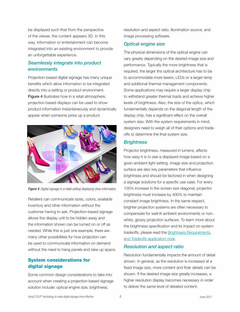
Figure 4 illustrates how in a retail atmosphere,
projection based displays can be used to show
product information instantaneously and dynamically
appear when someone picks up a product.
Retailers can communicate sizes, colors, available
inventory and other information without the
customer having to ask. Projection-based signage
allows the display unit to be hidden away and
the information shown can be turned on or off as
needed. While this is just one example, there are
many other possibilities for how projection can
be used to communicate information on demand
without the need to hang panels and take up space.
System considerations for digital signage
Some common design considerations to take into
account when creating a projection-based signage
solution include: optical engine size, brightness,
resolution and aspect ratio, illumination source, and
image processing software.
Optical engine size
The physical dimensions of the optical engine can
vary greatly depending on the desired image size and
performance. Typically the more brightness that is
required, the larger the optical architecture has to be
to accommodate more lasers, LEDs or a larger lamp
and additional thermal management components.
Some applications may require a larger display chip
to withstand greater thermal loads and achieve higher
levels of brightness. Also, the size of the optics, which
fundamentally depends on the diagonal length of the
display chip, has a significant effect on the overall
system size. With the system requirements in mind,
designers need to weigh all of their options and trade-
offs to determine the final system size.
Brightness
Projector brightness, measured in lumens, affects
how easy it is to see a displayed image based on a
given ambient light setting. Image size and projection
surface are also key parameters that influence
brightness and should be factored in when designing
a signage solutions for a specific use case. For every
100% increase in the screen size diagonal, projector
brightness must increase by 400% to maintain
constant image brightness. In the same respect,
brighter projection systems are often necessary to
compensate for well-lit ambient environments or non-
white, glossy projection surfaces. To learn more about
the brightness specification and its impact on system
tradeoffs, please read the Brightness Requirements
and Tradeoffs application note.
Resolution and aspect ratio
Resolution fundamentally impacts the amount of detail
shown. In general, as the resolution is increased at a
fixed image size, more content and finer details can be
shown. If the desired image size greatly increases, a
higher resolution display becomes necessary in order
to deliver the same level of detailed content.
Figure 4. Digital signage in a retail setting displaying shoe information.
I 5 Using TI DLP® technology to make digital signage more effective June 2017
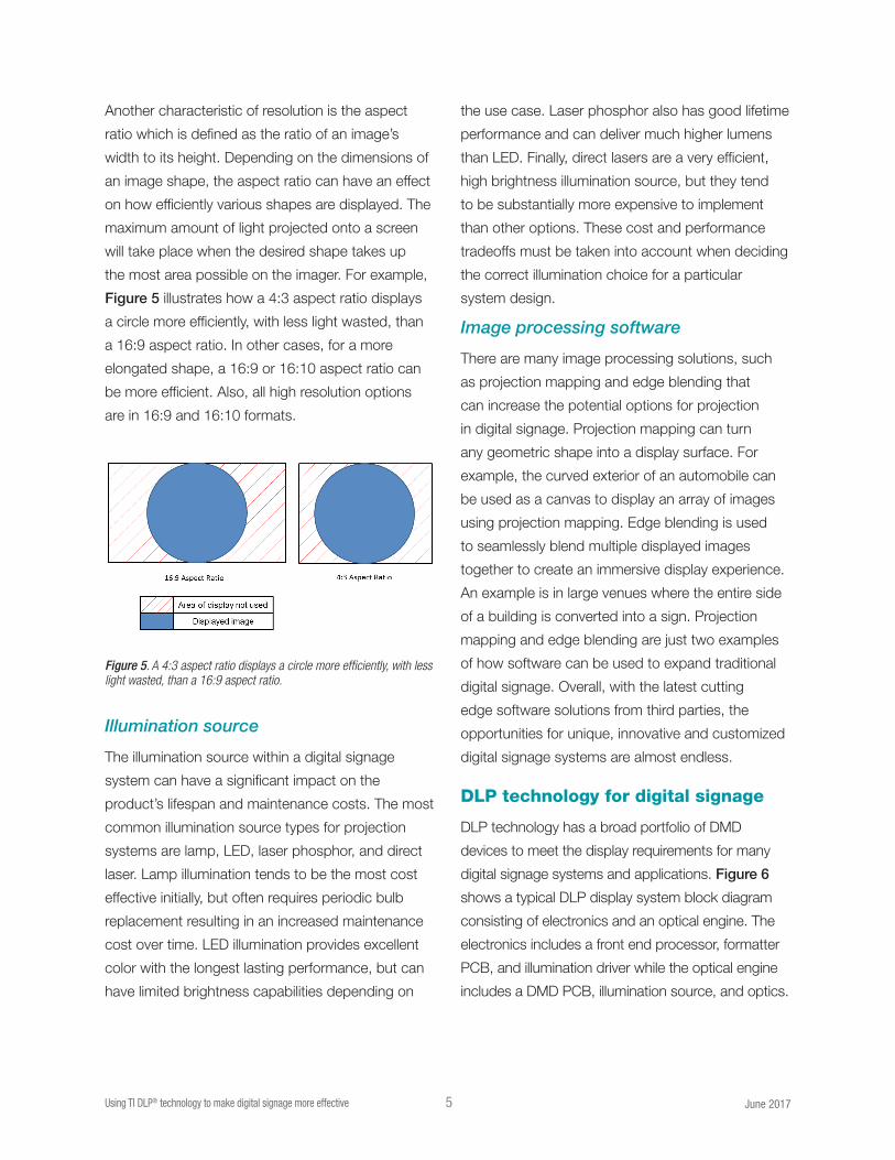
Figure 5. A 4:3 aspect ratio displays a circle more efficiently, with less light wasted, than a 16:9 aspect ratio.
Another characteristic of resolution is the aspect
ratio which is defined as the ratio of an image’s
width to its height. Depending on the dimensions of
an image shape, the aspect ratio can have an effect
on how efficiently various shapes are displayed. The
maximum amount of light projected onto a screen
will take place when the desired shape takes up
the most area possible on the imager. For example,
Figure 5 illustrates how a 4:3 aspect ratio displays
a circle more efficiently, with less light wasted, than
a 16:9 aspect ratio. In other cases, for a more
elongated shape, a 16:9 or 16:10 aspect ratio can
be more efficient. Also, all high resolution options
are in 16:9 and 16:10 formats.
Illumination source
The illumination source within a digital signage
system can have a significant impact on the
product’s lifespan and maintenance costs. The most
common illumination source types for projection
systems are lamp, LED, laser phosphor, and direct
laser. Lamp illumination tends to be the most cost
effective initially, but often requires periodic bulb
replacement resulting in an increased maintenance
cost over time. LED illumination provides excellent
color with the longest lasting performance, but can
have limited brightness capabilities depending on
the use case. Laser phosphor also has good lifetime
performance and can deliver much higher lumens
than LED. Finally, direct lasers are a very efficient,
high brightness illumination source, but they tend
to be substantially more expensive to implement
than other options. These cost and performance
tradeoffs must be taken into account when deciding
the correct illumination choice for a particular
system design.
Image processing software
There are many image processing solutions, such
as projection mapping and edge blending that
can increase the potential options for projection
in digital signage. Projection mapping can turn
any geometric shape into a display surface. For
example, the curved exterior of an automobile can
be used as a canvas to display an array of images
using projection mapping. Edge blending is used
to seamlessly blend multiple displayed images
together to create an immersive display experience.
An example is in large venues where the entire side
of a building is converted into a sign. Projection
mapping and edge blending are just two examples
of how software can be used to expand traditional
digital signage. Overall, with the latest cutting
edge software solutions from third parties, the
opportunities for unique, innovative and customized
digital signage systems are almost endless.
DLP technology for digital signage
DLP technology has a broad portfolio of DMD
devices to meet the display requirements for many
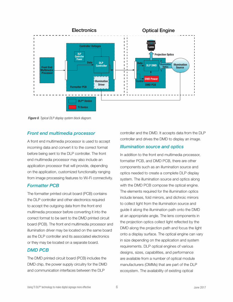
digital signage systems and applications. Figure 6
shows a typical DLP display system block diagram
consisting of electronics and an optical engine. The
electronics includes a front end processor, formatter
PCB, and illumination driver while the optical engine
includes a DMD PCB, illumination source, and optics.
I 6 Using TI DLP® technology to make digital signage more effective June 2017
Front end multimedia processor
A front end multimedia processor is used to accept
incoming data and convert it to the correct format
before being sent to the DLP controller. The front
end multimedia processor may also include an
application processor that will provide, depending
on the application, customized functionality ranging
from image processing features to Wi-Fi connectivity.
Formatter PCB
The formatter printed circuit board (PCB) contains
the DLP controller and other electronics required
to accept the outgoing data from the front end
multimedia processor before converting it into the
correct format to be sent to the DMD printed circuit
board (PCB). The front end multimedia processor and
illumination driver may be located on the same board
as the DLP controller and its associated electronics
or they may be located on a separate board.
DMD PCB
The DMD printed circuit board (PCB) includes the
DMD chip, the power supply circuitry for the DMD
and communication interfaces between the DLP
controller and the DMD. It accepts data from the DLP
controller and drives the DMD to display an image.
Illumination source and optics
In addition to the front end multimedia processor,
formatter PCB, and DMD PCB, there are other
components such as an illumination source and
optics needed to create a complete DLP display
system. The illumination source and optics along
with the DMD PCB compose the optical engine.
The elements required for the illumination optics
include lenses, fold mirrors, and dichroic mirrors
to collect light from the illumination source and
guide it along the illumination path onto the DMD
at an appropriate angle. The lens components in
the projection optics collect light reflected by the
DMD along the projection path and focus the light
onto a display surface. The optical engine can vary
in size depending on the application and system
requirements. DLP optical engines of various
designs, sizes, capabilities, and performance
are available from a number of optical module
manufacturers (OMMs) that are part of the DLP
ecosystem. The availability of existing optical
Front End Multimedia Processor
DLP Controller
Formatter PCB
DLPController
Power
DMD Power
DMD PCB
IlluminationOptics
Projection Optics
Controller Voltages
IlluminationSource
Lens
DataDLP DMD
Data
Control
DLP® Device
TI Device
IlluminationDriver
Electronics Optical Engine
Figure 6. Typical DLP display system block diagram.

I 7 Using TI DLP® technology to make digital signage more effective June 2017
engines allows for end equipment producers to
accelerate a product development cycle without
requiring specific expertise or resources.
DLP technology advantages
DLP technology has several key advantages that
make it ideal for digital signage:
• Resolution and Form Factor – Various DLP
imager resolutions, from nHD to 4 K UHD, and
package types are available to enable a range
of signage system dimensions and performance
capabilities all while delivering beautiful video
and images.
• High Contrast – DLP technology can enable a
high contrast ratio up to 2000:1, which creates
deep blacks, improves perceived brightness, and
image quality.
• Brightness – DLP technology is used in projectors
that display from 500 lumens up to 60,000 lumens.
DLP chipsets have thermal properties capable
of large, high brightness displays for vivid and
attention-grabbing digital signage.
• Power Efficiency – DLP digital micromirror
devices (DMDs) incorporate highly reflective,
aluminum micromirrors, which enable bright,
power efficient, digital signage products.
• Light Source Agnostic – DLP technology
is compatible with virtually any light source,
including lasers and LEDs, allowing designers
maximum versatility across signage use cases.
DLP chipsets for digital signage
Texas Instruments offers a wide portfolio of DLP
DMD devices that suit the versatile needs of digital
signage applications. Please visit ti.com/dlp for the
most current list of DLP chips offered from Texas
instruments. Table 1 shows a snapshot of DMDs
that are well suited for digital signage applications.
DMD DLP3010 DLP4501 DLP4710 0.65” WXGA 0.65” 1080p DLP660TE
Display Resolution 1280 x 720 1280 x 800 1920 x 1080 1280 x 800 1920 x 1080 3840 x 2160
Native Aspect Ratio 16:9 16:10 16:9 16:10 16:9 16:10
Micromirror array diagonal (inch) 0.3 0.45 0.47 0.65 0.65 0.66
Typical Brightness (lumens) 150-300 150-1000 150-1500 1500-4000 1500-4000 1500-5000
Controller DLPC3433 DLPC6401 DLPC3439 (2) DLPC4422 DLPC4422 DLPC4422 (2)
Power management/ illumination driver — — DLPA3000/DLPA3005 DLPA100 DLPA100 DLPA100
Micromirror or type Orthogonal Orthogonal Orthogonal Orthogonal Orthogonal Orthogonal
Micromirror pitch (µm) 5.4 7.6 5.4 7.6 7.6 5.4
Design Support Pico Design Network Standard Display Design Network
Table 1. DLP chipset portfolio for digital signage – visit ti.com/dlp for all DLP chip options.

© 2017 Texas Instruments Incorporated DLPY001The platform bar is a trademark of Texas Instruments. All other trademarks are the property of their respective owners.
Important Notice: The products and services of Texas Instruments Incorporated and its subsidiaries described herein are sold subject to TI’s standard terms and conditions of sale. Customers are advised to obtain the most current and complete information about TI products and services before placing orders. TI assumes no liability for applications assistance, customer’s applications or product designs, software performance, or infringement of patents. The publication of information regarding any other company’s products or services does not constitute TI’s approval, warranty or endorsement thereof.
Reference material to get started with DLP technology for digital signage solutions
1. Learn more about DLP technology
How DLP Technology Works Video
Getting Started
2. Download a TI Design reference design to speed
product development using DLP schematics, layout
files, BOM, and test reports
4K UHD High Brightness Display Reference
Design
Compact Full HD 1080p Projection Display
Reference Design
Portable, Low Power HD Projection Display using
DLP Technology
3. Check out TI’s E2E community to search for
solutions, get help, share knowledge, and solve
problems with fellow engineers and TI experts
TI’s E2ETM Community
IMPORTANT NOTICE FOR TI DESIGN INFORMATION AND RESOURCES
Texas Instruments Incorporated (‘TI”) technical, application or other design advice, services or information, including, but not limited to,reference designs and materials relating to evaluation modules, (collectively, “TI Resources”) are intended to assist designers who aredeveloping applications that incorporate TI products; by downloading, accessing or using any particular TI Resource in any way, you(individually or, if you are acting on behalf of a company, your company) agree to use it solely for this purpose and subject to the terms ofthis Notice.TI’s provision of TI Resources does not expand or otherwise alter TI’s applicable published warranties or warranty disclaimers for TIproducts, and no additional obligations or liabilities arise from TI providing such TI Resources. TI reserves the right to make corrections,enhancements, improvements and other changes to its TI Resources.You understand and agree that you remain responsible for using your independent analysis, evaluation and judgment in designing yourapplications and that you have full and exclusive responsibility to assure the safety of your applications and compliance of your applications(and of all TI products used in or for your applications) with all applicable regulations, laws and other applicable requirements. Yourepresent that, with respect to your applications, you have all the necessary expertise to create and implement safeguards that (1)anticipate dangerous consequences of failures, (2) monitor failures and their consequences, and (3) lessen the likelihood of failures thatmight cause harm and take appropriate actions. You agree that prior to using or distributing any applications that include TI products, youwill thoroughly test such applications and the functionality of such TI products as used in such applications. TI has not conducted anytesting other than that specifically described in the published documentation for a particular TI Resource.You are authorized to use, copy and modify any individual TI Resource only in connection with the development of applications that includethe TI product(s) identified in such TI Resource. NO OTHER LICENSE, EXPRESS OR IMPLIED, BY ESTOPPEL OR OTHERWISE TOANY OTHER TI INTELLECTUAL PROPERTY RIGHT, AND NO LICENSE TO ANY TECHNOLOGY OR INTELLECTUAL PROPERTYRIGHT OF TI OR ANY THIRD PARTY IS GRANTED HEREIN, including but not limited to any patent right, copyright, mask work right, orother intellectual property right relating to any combination, machine, or process in which TI products or services are used. Informationregarding or referencing third-party products or services does not constitute a license to use such products or services, or a warranty orendorsement thereof. Use of TI Resources may require a license from a third party under the patents or other intellectual property of thethird party, or a license from TI under the patents or other intellectual property of TI.TI RESOURCES ARE PROVIDED “AS IS” AND WITH ALL FAULTS. TI DISCLAIMS ALL OTHER WARRANTIES ORREPRESENTATIONS, EXPRESS OR IMPLIED, REGARDING TI RESOURCES OR USE THEREOF, INCLUDING BUT NOT LIMITED TOACCURACY OR COMPLETENESS, TITLE, ANY EPIDEMIC FAILURE WARRANTY AND ANY IMPLIED WARRANTIES OFMERCHANTABILITY, FITNESS FOR A PARTICULAR PURPOSE, AND NON-INFRINGEMENT OF ANY THIRD PARTY INTELLECTUALPROPERTY RIGHTS.TI SHALL NOT BE LIABLE FOR AND SHALL NOT DEFEND OR INDEMNIFY YOU AGAINST ANY CLAIM, INCLUDING BUT NOTLIMITED TO ANY INFRINGEMENT CLAIM THAT RELATES TO OR IS BASED ON ANY COMBINATION OF PRODUCTS EVEN IFDESCRIBED IN TI RESOURCES OR OTHERWISE. IN NO EVENT SHALL TI BE LIABLE FOR ANY ACTUAL, DIRECT, SPECIAL,COLLATERAL, INDIRECT, PUNITIVE, INCIDENTAL, CONSEQUENTIAL OR EXEMPLARY DAMAGES IN CONNECTION WITH ORARISING OUT OF TI RESOURCES OR USE THEREOF, AND REGARDLESS OF WHETHER TI HAS BEEN ADVISED OF THEPOSSIBILITY OF SUCH DAMAGES.You agree to fully indemnify TI and its representatives against any damages, costs, losses, and/or liabilities arising out of your non-compliance with the terms and provisions of this Notice.This Notice applies to TI Resources. Additional terms apply to the use and purchase of certain types of materials, TI products and services.These include; without limitation, TI’s standard terms for semiconductor products http://www.ti.com/sc/docs/stdterms.htm), evaluationmodules, and samples (http://www.ti.com/sc/docs/sampterms.htm).
Mailing Address: Texas Instruments, Post Office Box 655303, Dallas, Texas 75265Copyright © 2017, Texas Instruments Incorporated


