Using Ultracapacitors in Photovoltaic Systems. A technical proposal José Antonio Domínguez Vázquez, Fernando Martínez Rodrigo, José Miguel Ruiz and Santiago Lorenzo Matilla Department of Electronic Technology E.T.S.I.I. Valladolid University Paseo del Cauce s/n, 47011 Valladolid, Spain. Phone +34 983 42 33 38, fax +34 983 42 33 10, e-mail: [email protected]1.Introduction In this paper we expose a new strategy to deliver the power of a Photovoltaic (or any other energy source of small power) System attached to the main. The object of the implementation of a battery ofultracapacitors in the photovoltaic system is to convert a variable power delivery to constant power. This will improve the energy efficiency by two ways. One is to take advantage of the time in which the system does not work because the power flow is too low (irradiation). Another advantage is that the output power is lower than input power. The last affirmation is obvious showing the next figure 1: Figure 1: Several strategies depending of outputpower inverter. 1.____ Input power of the renewable power plant(photovoltaic Panels in this case) 2..... Output power of inverter P1 3.__ Output power of inverter P2 such P2<P1 4.·-·- Output power of inverter P3 such P3<P2<P1 It’s obvious that input energy integer value can be obtained by several ways. So we can study which output power is the best choice for our energy source choosing an the inverter that works the most time in its best efficiency ratio. Key words: ultracapacitors, constant output power, equalization 2.Modelling the system. A. Irradiance modellingWe need to know the basic equations of our energy source. In this case, the sun irradiation. In order to simplify as possible, we can consider irradiation is modelled by a gaussian expression. Next equation 1 will show the beha viour of daily irradiation, wher e its maximum is 1, and the base is 12 hours wide. ( ) 2 12 2 1 1 − − ⋅ = dx e Gdσ Equation 1: daily irradiation. σ d= 2.65 The annual irradiation is considered as a gaussian modulation. This function reaches its maximum at the half of the year and its supossed about 1000 W/m². In order to determine the variance we consider the maximum irradiance of one day. This day must be at the beginning or at the finish of the year. SO annual expression for irradiation is: ( ) 2 4380 2 1 − − ⋅ = a x e A Gdσ Equation 2: annual irradiation. σ d= 3000 and A=1.1 kW/m²Two aleatory variables will simulate the effect of the climatology conditions like clouds. The product ofthese four elements will provides us the annual irradiance that must verify one condition: its integermust be the measured annual irradiance. GdGa G Total× = Equation 3: Total annual irradiance. At this moment we have to adjust some of the values calculated before. Troubles appear considering daily irradiation as a Gaussian function, where the maximum value is reached at one instant only. Actually the maximum values, specially in summer, are reached during several hours. In order to resolve this problem
Transcript
8/6/2019 Using Ultra Capacitors in Photo Voltaic Systems. a Technical Proposal
In this paper we expose a new strategy to deliver the power of a Photovoltaic (or any other energy source
of small power) System attached to the main. Theobject of the implementation of a battery of ultracapacitors in the photovoltaic system is toconvert a variable power delivery to constant power.This will improve the energy efficiency by two ways.One is to take advantage of the time in which thesystem does not work because the power flow is too
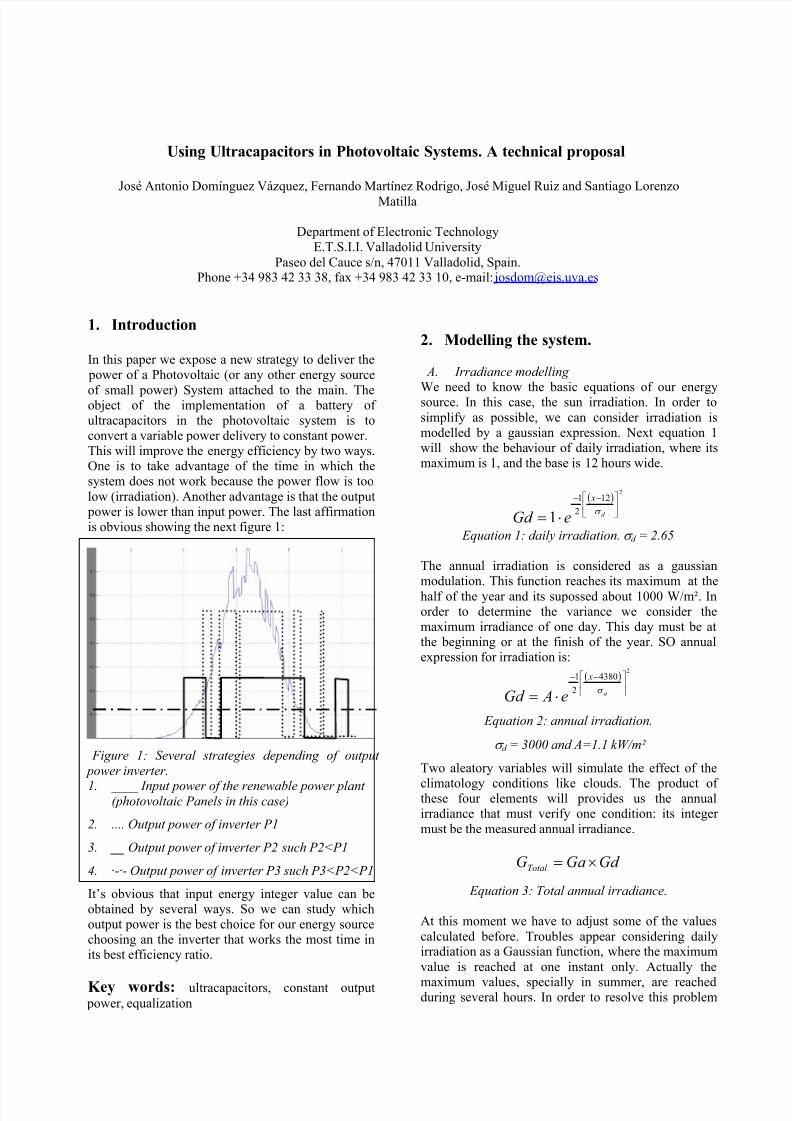
low (irradiation). Another advantage is that the output power is lower than input power. The last affirmationis obvious showing the next figure 1:
Figure 1: Several strategies depending of output
power inverter.
1. ____ Input power of the renewable power plant (photovoltaic Panels in this case)
2. .... Output power of inverter P1
3. __ Output power of inverter P2 such P2<P1
4. ·-·- Output power of inverter P3 such P3<P2<P1
It’s obvious that input energy integer value can beobtained by several ways. So we can study whichoutput power is the best choice for our energy sourcechoosing an the inverter that works the most time inits best efficiency ratio.
We need to know the basic equations of our energysource. In this case, the sun irradiation. In order to
simplify as possible, we can consider irradiation ismodelled by a gaussian expression. Next equation 1will show the behaviour of daily irradiation, where itsmaximum is 1, and the base is 12 hours wide.
( )2
12
2
1
1
−−
⋅= d
x
eGd σ
Equation 1: daily irradiation. σ d = 2.65
The annual irradiation is considered as a gaussianmodulation. This function reaches its maximum at the
half of the year and its supossed about 1000 W/m². Inorder to determine the variance we consider themaximum irradiance of one day. This day must be atthe beginning or at the finish of the year. SO annualexpression for irradiation is:
( )2
4380
2
1
−−
⋅= a
x
e AGd σ
Equation 2: annual irradiation.
σ d = 3000 and A=1.1 kW/m²
Two aleatory variables will simulate the effect of the
climatology conditions like clouds. The product of these four elements will provides us the annualirradiance that must verify one condition: its integer
must be the measured annual irradiance.
Gd GaGTotal ×=
Equation 3: Total annual irradiance.
At this moment we have to adjust some of the values
calculated before. Troubles appear considering dailyirradiation as a Gaussian function, where the maximum
value is reached at one instant only. Actually the
maximum values, specially in summer, are reachedduring several hours. In order to resolve this problem
8/6/2019 Using Ultra Capacitors in Photo Voltaic Systems. a Technical Proposal
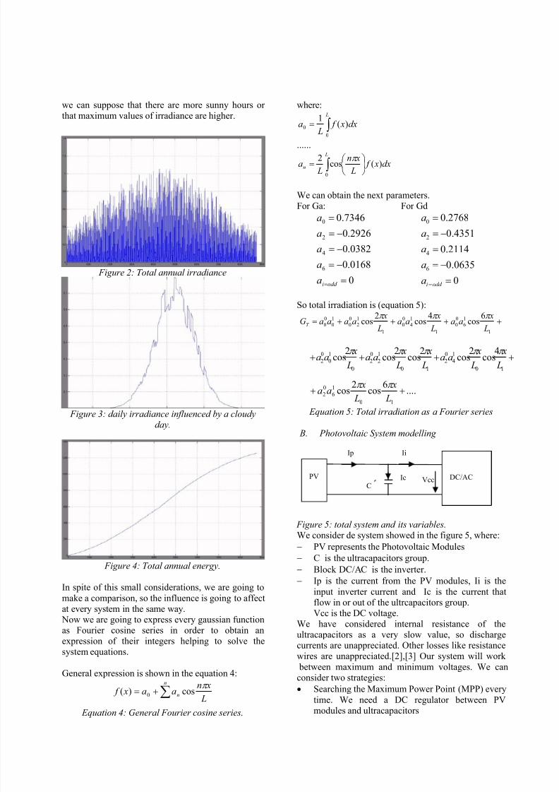
we can suppose that there are more sunny hours or that maximum values of irradiance are higher.
Figure 2: Total annual irradiance
Figure 3: daily irradiance influenced by a cloudyday.
Figure 4: Total annual energy.
In spite of this small considerations, we are going to
make a comparison, so the influence is going to affectat every system in the same way. Now we are going to express every gaussian functionas Fourier cosine series in order to obtain anexpression of their integers helping to solve thesystem equations.
General expression is shown in the equation 4:
∑+=
n
n L
xn
aa x f
π
cos)( 0
Equation 4: General Fourier cosine series.
where:
∫ = L
dx x f L
a0
0 )(1
......
dx x f L
xn
La
L
n )(cos2
0
∫
=
π
We can obtain the next parameters.For Ga: For Gd
0
0168.0
0382.0
2926.0
7346.0
6
4
2
0
=
−=
−=
−=
=
=odd ia
a
a
a
a
0
0635.0
2114.0
4351.0
2768.0
6
4
2
0
=
−=
=
−=
=
=odd ia
a
a
a
a
So total irradiation is (equation 5):
++++=1
1
6
0
0
1
1
4
0
0
1
1
2
0
0
1
0
0
0
6cos
4cos
2cos
L
xaa
L
xaa
L
xaaaaGT
π π π
Equation 5: Total irradiation as a Fourier series
B. Photovoltaic System modelling
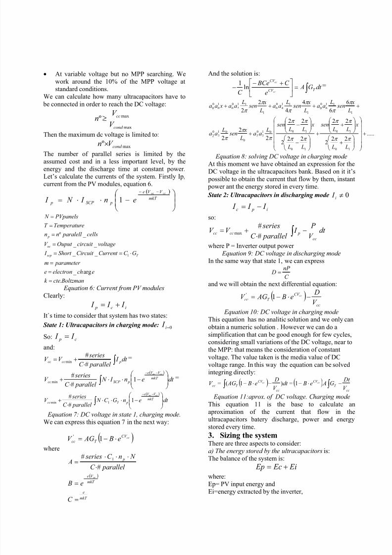
Figure 5: total system and its variables.We consider de system showed in the figure 5, where:
− PV represents the Photovoltaic Modules
− C is the ultracapacitors group.− Block DC/AC is the inverter.
− Ip is the current from the PV modules, Ii is the
input inverter current and Ic is the current thatflow in or out of the ultrcapacitors group.Vcc is the DC voltage.
We have considered internal resistance of theultracapacitors as a very slow value, so dischargecurrents are unappreciated. Other losses like resistancewires are unappreciated.[2],[3] Our system will work
between maximum and minimum voltages. We canconsider two strategies:
• Searching the Maximum Power Point (MPP) every
time. We need a DC regulator between PVmodules and ultracapacitors
++++10
1
4
0
2
10
1
2
0
2
0
1
0
0
2
4cos
2cos
2cos
2cos
2cos
L
x
L
xaa
L
x
L
xaa
L
xaa
π π π π π
....6
cos2
cos10
1
6
0
2 ++ L
x
L
xaa
π π
PV
DC/AC
Ip Ii
Ic VccC
8/6/2019 Using Ultra Capacitors in Photo Voltaic Systems. a Technical Proposal
• At variable voltage but no MPP searching. Wework around the 10% of the MPP voltage atstandard conditions.
We can calculate how many ultracapacitors have to be connected in order to reach the DC voltage:
max
maxºcond
cc
V
V n ≥
Then the maximum dc voltage is limited to:
maxº cond V n ×
The number of parallel series is limited by theassumed cost and in a less important level, by theenergy and the discharge time at constant power.Let’s calculate the currents of the system. Firstly Ip,current from the PV modules, equation 6.
( )
−⋅⋅=
−−
mkT
V V e
pSCP p
ccoc
en I N I 1
Boltzmanctek
echelectrone
parameter m
GC Current Circuit Short I
voltagecircuit Ouput V
cells paralell nn
eTemperatur T
PVpanels N
T scp
oc
p
.
arg _
_ _
_ _
_ º
1
=
=
=
⋅==
=
=
=
=
Equation 6: Current from PV modules
Clearly:
ic p I I I +=
It`s time to consider that system has two states:
State 1: Ultracapacitors in charging mode: 0=i I
So: c p I I =
and:
∫ ⋅+= dt I
parallel C
seriesV V pcccc
#
#min
=
( )
∫
−⋅⋅
⋅+
−−
dt en I N parallel C
seriesV mkT
V V e
pSCP cc
ccoc
1#
#min
=
( )
∫
−⋅⋅⋅
⋅+
−−
dt enGC N parallel C
seriesV mkT
V V e
pT cc
ccoc
1#
#1min
Equation 7: DC voltage in state 1, charging mode.We can express this equation 7 in the next way:
( )ccCV
T cc e B AGV ⋅−= 1'
where
( )
mkT
e
mkT
V e
p
C
e B
parallel C
N nC series A
oc
=
=
⋅
⋅⋅⋅=
−
#
# 1
And the solution is:
∫ =
+−− dt G A
e
C BCe
C T CV
CV
cc
cc
ln1 =
.....22
2
22
222
22
2
2
2
6
6
4
4
2
2
10
10
10
1001
2
0
2
0
01
2
0
2
1
11
6
0
0
1
11
4
0
0
1
11
2
0
0
1
0
0
0
+
+
+
+
−
−
+
++++
L L
x L L
sen
L L
x L L
sen L
aa L
x sen
Laa
L
x sen
Laa
L
x sen
Laa
L
x sen
Laa xaa
π π
π π
π π
π π
π
π
π
π
π
π
π
π
π
Equation 8: solving DC voltage in charging mode At this moment we have obtained an expression for theDC voltage in the ultracapacitors bank. Based on it it’s
possible to obtain the current that flow by them, instant power ant the energy stored in every time.
State 2: Ultracapacitors in discharging mode 0≠i I
i pc I I I −=
so:
∫ −⋅
+= dt V
P I
parallel C
seriesV V
cc
pcccc#
#max
where P = Inverter output power Equation 9: DC voltage in discharging mode
In the same way that state 1, we can express
C
nP D =
and we will obtain the next differential equation:
( )cc
CV
T ccV De B AGV cc −⋅−= 1'
Equation 10: DC voltage in charging modeThis equation has no analitic solution and we only can
obtain a numeric solution . However we can do asimplification that can be good enough for few cycles,considering small variations of the DC voltage, near tothe MPP: that means the consideration of constant
voltage. The value taken is the media value of DCvoltage range. In this way the equation can be solvedintegring directly:
( ) ( )cc
T
CV
cc
CV
T cc
V
Dt G Ae Bdt
V
De B AGV cccc −⋅−=−⋅−= ∫ ∫ 1)1(
Equation 11:aprox. of DC voltage. Charging mode
This equation 11 is the base to calculate anaproximation of the current that flow in theultracapacitors batery discharge, power and energystored every time.
3. Sizing the systemThere are three aspects to consider:a) The energy stored by the ultracapacitors is:The balance of the system is:
Ei Ec Ep +=
where:
Ep= PV input energy andEi=energy extracted by the inverter,
8/6/2019 Using Ultra Capacitors in Photo Voltaic Systems. a Technical Proposal
If Ep>Ei the the system will react, lowing the PV power:
- Rising the DC voltage or
- Cutting off the PV modules. This situation willgive a lower performance.
In order to well know this situation is necessary toanalize the irradiance of the placement. This situationcan be in the days with the highest annual irradiance.
Experimentally we can assure that a good criteria tochoose the output inverter power is the next:
hoursdailyof
e performanc PV EnergydailyMaximumSurfaceules PV P i
_ _ #
_ _ _ mod# ×××=
b) The discharging time has a short relation when weconsider the dead times when the system exceed the
supplied energy. It’s easy to calculate with nextequation. Also it can provides us the minimum andthe maximum time of the inverter working at constant
output power.
min
2)(2
1
T P
V nC
P
E T
ii
c
des ≤∆
==
c) The performance of the inverter . We can use agood approximation if we choose:
nin P P P ≤≤≈ %30
An evaluation of these three aspects will provide us a
good idea of the output power.
4. Strategies of controlWe present four strategies to control the system. Oneof them is a conventional system withoutultracapacitors in order to compare the results with
another three strategies using those elements.a) System 1: Conventional system: It works at
variable power. Starting at a minimum input power, and including a MPP tracking
b) System 2: Using ultracapacitors at variablevoltage depending of the ultracapacitors
characteristics. Inverter works at constantouptput power at its maximum eficiency.
c) System 3: Using ultracapacitors at variablevoltage. Tracking of the MPP with a DCregulator before the ultracapacitors. Stillmaximum and minimum working voltages.Inverter works at constant output power atits maximum efficiency.
d) System 4: Same at above but inverter worksat two different levels: normal level andupper level for extreme situation (very highinput PV power)
e) System 5: Hybrid strategy. We fix a working power. When PV system provides more
power , inverter works like a conventionalsystem. When input power is lower, we
charge and discharge the ultracapacitors atconstant power.
5. SimulationsWe have done simulations of every strategy control inMatlab at different conditions. We’ll provide several
graphics of the results. In this abstract we show theresults in a table
6. ConclusionSystem 5 provides the best efificiency rate in everycondition, so ultracapcitors can be a good solution toincrease the production of a Photvoltaic sytem.
7. References[1] Bobby Maher, “A Backup Power System Using
Ultracapacitors”, september 2004, pags 44-49www.powerelectronics.com.[2] NESS Capacitor Co. Ltd, several technical datas
[3] MAXWELL Technologies ultracapacitors, severaltechnical datas[4] L. Zubieta, R. Bonert, “Characterization of double-layer capacitors for power electronics applications”,IEEE Transactions on Industry Applications, January-February 2000, vol. 36, issue. 1, pp. 199-205.