100
Using VERITAS Cluster Server Jim Senicka Product Management VERITAS Software June 2001
Using VERITAS Cluster Server
Jim Senicka Product Management VERITAS Software
June 2001
Business Without Interruption
Using VERITAS Cluster Server 9/13/01 Page ii
Table of Contents
EXECUTIVE OVERVIEW ........................................................................................................................................4
CREDITS .........................................................................................................................................................................4
VCS BUILDING BLOCKS .........................................................................................................................................4 CLUSTERS...................................................................................................................................................................... 5 RESOURCES AND RESOURCE TYPES .......................................................................................................................... 5 AGENTS.......................................................................................................................................................................... 6 CLASSIFICATIONS OF VCS AGENTS.......................................................................................................................... 7
Bundled Agents........................................................................................................................................................7 Enterprise Agents....................................................................................................................................................7 Storage Agents.........................................................................................................................................................8 Custom Agents.........................................................................................................................................................8
SERVICE GROUPS ......................................................................................................................................................... 8 RESOURCE DEPENDENCIES.......................................................................................................................................... 9 TYPES OF SERVICE GROUPS...................................................................................................................................... 10
Failover Groups....................................................................................................................................................11 Parallel Groups.....................................................................................................................................................11
CLUSTER COMMUNICATIONS (HEARTBEAT ).......................................................................................................... 11 PUTTING THE PIECES T OGETHER.............................................................................................................................. 11
COMMON CLUSTER CONFIGURATION TASKS .......................................................................................13 HEARTBEAT NETWORK CONFIGURATION................................................................................................................ 13 STORAGE CONFIGURATION....................................................................................................................................... 14
Dual hosted SCSI..................................................................................................................................................14 Storage Area Networks........................................................................................................................................17 Storage Configuration Sequence........................................................................................................................17
APPLICATION SETUP................................................................................................................................................... 18 PUBLIC NETWORK DETAILS...................................................................................................................................... 19 INITIAL VCS INSTALL AND SETUP ........................................................................................................................... 19 COMMUNICATION VERIFICATION............................................................................................................................. 19
LLT ..........................................................................................................................................................................20 GAB .........................................................................................................................................................................20 Cluster operation ..................................................................................................................................................21
VCS CONFIGURATION CONCEPTS.................................................................................................................21 CONFIGURATION FILE LOCATIONS........................................................................................................................... 21 MAIN.CF FILE CONTENTS........................................................................................................................................... 22 SAMPLE INITIAL CONFIGURATION........................................................................................................................... 23 SAMPLE TWO NODE ASYMMETRIC NFS CLUSTER................................................................................................. 23
Example main.cf file.............................................................................................................................................24 RESOURCE TYPE DEFINITIONS.................................................................................................................................. 25 ATTRIBUTES................................................................................................................................................................ 27
Type dependant attributes...................................................................................................................................28 Type independent attributes................................................................................................................................29 Resource specific attributes................................................................................................................................29 Type specific attributes........................................................................................................................................29 Local and Global attributes................................................................................................................................30
MODIFYING THE CONFIGURATION .............................................................................................................30 MODIFYING THE MAIN.CF FILE................................................................................................................................. 31
Using VERITAS Cluster Server 9/13/01 Page 1
MODIFYING THE CONFIGURATION FROM THE COMMAND LINE............................................................................ 31 MODIFYING THE CONFIGURATION USING THE GUI............................................................................................... 31 ADDING SNMP TRAPS.............................................................................................................................................. 31 USING PROXY RESOURCES ....................................................................................................................................... 32
CONFIGURATION FILE REPLICATION ........................................................................................................32 VCS STARTUP............................................................................................................................................................. 32 VCS SHUTDOWN........................................................................................................................................................ 34 STALE CONFIGURATIONS........................................................................................................................................... 36 WORKING EXAMPLES................................................................................................................................................. 36
NFS SAMPLE CONFIGURATIONS ....................................................................................................................37 TWO NODE SYMMETRICAL NFS CONFIGURATION................................................................................................. 37
Example main.cf file.............................................................................................................................................38 COMMAND LINE MODIFICATION EXAMPLE............................................................................................................. 39 USING A NIC PROXY.................................................................................................................................................. 40
Example main.cf file.............................................................................................................................................41 CONFIGURING A PARALLEL NIC GROUP AND USING PROXY............................................................................... 42
Example main.cf....................................................................................................................................................42 SPECIAL STORAGE CONSIDERATIONS FOR NFS SERVICE ..................................................................................... 44
ORACLE SAMPLE CONFIGURATIONS..........................................................................................................45 ORACLE SETUP............................................................................................................................................................ 45 ORACLE ENTERPRISE AGENT INSTALLATION......................................................................................................... 46 SINGLE INSTANCE CONFIGURATION......................................................................................................................... 46
Example main.cf....................................................................................................................................................47 Oracle listener.ora configuration ......................................................................................................................48
ADDING DEEP LEVEL TESTING.................................................................................................................................. 49 Oracle changes......................................................................................................................................................49 VCS Configuration changes................................................................................................................................50
MULTIPLE INSTANCE CONFIGURATION................................................................................................................... 50 Example main.cf....................................................................................................................................................51 Oracle listener.ora configuration ......................................................................................................................54
LOCATION OF ORACLE BINARIES............................................................................................................................. 55 Oracle binaries on shared disk...........................................................................................................................55 Oracle binaries on local disk..............................................................................................................................55 What is the correct choice?.................................................................................................................................56
USING IPMULTINIC AND MULTINICA..........................................................................................................56 CONFIGURING IPMULTINIC AND MULTINICA RESOURCE PAIRS..................................................................... 56
Example main.cf....................................................................................................................................................57 NOTES ABOUT USING MULTINICA AGENT........................................................................................................... 58 USING A PARALLEL MULTINICA GROUP AND PROXY......................................................................................... 58
Example main.cf....................................................................................................................................................58 ALTERING AGENT/RESOURCE TYPE BEHAVIOR..................................................................................60
COMMON RESOURCE TYPE ATTRIBUTES................................................................................................................. 60 ConfInterval...........................................................................................................................................................60 FaultOnMonitorTimeouts....................................................................................................................................60 MonitorInterval.....................................................................................................................................................61 MonitorTimeout.....................................................................................................................................................61 OfflineMonitorInterval.........................................................................................................................................61 OfflineTimeout.......................................................................................................................................................61 OnlineRetryLimit...................................................................................................................................................61 OnlineTimeout.......................................................................................................................................................62
Using VERITAS Cluster Server 9/13/01 Page 2
RestartLimit ...........................................................................................................................................................62 ToleranceLimit ......................................................................................................................................................62
USAGE EXAMPLE........................................................................................................................................................ 62 CONFIGURING DIFFERENT AGENT BEHAVIOR FOR MULTIPLE RESOURCES......................................................... 63
SERVICE GROUP WORKLOAD MANAGEMENT (SGWM) ....................................................................64 SGWM CONCEPTS..................................................................................................................................................... 64
System Capacity and Service Group Load.......................................................................................................65 Static Load vs. Dynamic Load............................................................................................................................65 Limits and Prerequisites......................................................................................................................................66 Capacity and Limits Together............................................................................................................................66 Overload Warning................................................................................................................................................67 SystemZones...........................................................................................................................................................67 Load Based AutoStart ..........................................................................................................................................67
CONFIGURING SGWM............................................................................................................................................... 68 System attributes...................................................................................................................................................68 Service Group Attributes.....................................................................................................................................70
MAIN.CF USAGE ......................................................................................................................................................... 71 SGWM EXAMPLES.................................................................................................................................................... 72
Simple 4-node limits only example....................................................................................................................72 Simple 4-node load based example....................................................................................................................74 Complex 4-node example....................................................................................................................................77 Server Consolidation Example...........................................................................................................................81
COMMON PROBLEMS ...........................................................................................................................................86 AUTODISABLED SERVICE GROUPS.......................................................................................................................... 86 RESOURCES NOT PROBED......................................................................................................................................... 86 STALE/INVALID CONFIGURATION............................................................................................................................ 87 APPLICATION/RESOURCES NOT STARTING ............................................................................................................. 87
FAILOVER TIMES AND OTHER PERFORMANCE ISSUES ...................................................................87 VCS FAILURE DETECTION/FAILOVER PERFORMANCE......................................................................................... 87
Bringing a Service Group Online......................................................................................................................88 Taking a Service Group Offline..........................................................................................................................88 Bringing a Resource Online................................................................................................................................88 Taking a Resource Offline...................................................................................................................................88 Service Group Switch...........................................................................................................................................89 Service Group Failover .......................................................................................................................................89 Detecting Resource Failure................................................................................................................................89 Detecting System Failure ....................................................................................................................................90 Detecting Network Link Failure.........................................................................................................................90 Cluster Boot Time .................................................................................................................................................90
IMPACT OF VCS ON OVERALL SYSTEM PERFORMANCE...................................................................................... 91 Kernel Components (GAB and LLT) .................................................................................................................91 VCS Engine............................................................................................................................................................91
REDUCING FAILOVER TIME ...................................................................................................................................... 92 Reducing Database Recovery Time ...................................................................................................................92 Reducing Storage Import Time ...........................................................................................................................92
RECOMMENDED CONFIGURATIONS ...........................................................................................................93 ELIMINATE SINGLE POINTS OF FAILURE................................................................................................................. 93
Heartbeat Network ...............................................................................................................................................93 Public network.......................................................................................................................................................93 Disk Storage...........................................................................................................................................................94 Avoid Failover! .....................................................................................................................................................94
Using VERITAS Cluster Server 9/13/01 Page 3
BUILDING A SOLID FOUNDATION............................................................................................................................. 95 System Availability, Scalability and Performance..........................................................................................95 Data Availability...................................................................................................................................................96 Application Availability.......................................................................................................................................96
THINGS TO AVOID...................................................................................................................................................... 96 Using Outside Name Services.............................................................................................................................96 NFS File Service...................................................................................................................................................97 Using NFS in the Cluster.....................................................................................................................................97
CLUSTER CONFIGURATION ....................................................................................................................................... 97 Number of nodes ...................................................................................................................................................97 Storage Configuration..........................................................................................................................................98
Using VERITAS Cluster Server 9/13/01 Page 4
Executive Overview This document is intended for System Administrators, System Architects, IT Managers and other IT professionals interested in increasing application availability through the use of VERITAS Cluster Server (VCS). This white paper is intended to provide information on configuration and use of the second-generation High Availability product, VERITAS Cluster Server. The white paper will describe terminology, technology and common configurations. It is not designed to replace standard VERITAS documentation, but rather to act as an additional source of information for IT professionals wishing to deploy the VERITAS Cluster Server
This paper is part of a series on VCS. Other papers include Managing Application Availability with VCS, VCS Daemons and Communications, VCS Agent Development and VCS Frequently Asked Questions.
Credits Special thanks to the following VERITAS folks:
Darshan Joshi, Shardul Divatia, Phil French and Kaushal Dalal and the rest of the VCS Engineering team for answering hundreds of questions.
Tom Stephens for providing the initial FAQ list, guidance, humor and constant review
Evan Marcus for providing customer needs, multiple review cycles and co-authoring what is, in my opinion, the best book on High Availability published, “Blueprints for High Availability. Designing Resilient Distributed Systems”
VCS Building Blocks At first glance, VCS seems to be a very complex package. By breaking the technology into understandable blocks, it can be explained in a much simpler fashion. The following section will describe each major building block in a VCS configuration. Understanding each of these items as well as interaction with others is key to understanding VCS. The primary items to discuss include the following:
• Clusters
• Resources and resource types
• Resource Categories
• Agents
Using VERITAS Cluster Server 9/13/01 Page 5
• Agent Classifications
• Service Groups
• Resource Dependencies
• Heartbeat
Clusters A single VCS cluster consists of multiple systems connected in various combinations to shared storage devices. VCS monitors and controls applications running in the cluster, and can restart applications in response to a variety of hardware or software faults. A cluster is defined as all systems with the same cluster-ID and connected via a set of redundant heartbeat networks. (See the VCS Daemons and Communications white paper for a detailed discussion on cluster ID and heartbeat networks). Clusters can have from 1 to 32 member systems, or “nodes”. All nodes in the cluster are constantly aware of the status of all resources on all other nodes. Applications can be configured to run on specific nodes in the cluster. Storage is configured to provide access to shared application data for those systems hosting the application. In that respect, the actual storage connectivity will determine where applications can be run. Nodes sharing access to storage will be “eligible” to run an application. Nodes without common storage cannot failover an application that stores data to disk.
Within a single VCS cluster, all member nodes must run the same operating system family. For example, a Solaris cluster would consist of entirely Solaris nodes, likewise with HP/UX and NT clusters. Multiple clusters can all be managed from one central console with the Cluster Server Cluster Manager.
The Cluster Manager allows an administrator to log in and manage a virtually unlimited number of VCS clusters, using one common GUI and command line interface. The common GUI and command line interface is one of the most powerful features of VCS. NT and Unix versions have an identical user interface.
Resources and Resource Types Resources are hardware or software entities, such as disks, network interface cards (NICs), IP addresses, applications, and databases, which are controlled by VCS. Controlling a resource means bringing it online (starting), taking it offline (stopping) as well as monitoring the health or status of the resource.
Resources are classified according to types, and multiple resources can be of a single type; for example, two disk resources are both classified as type Disk. How VCS starts and stops a resource is specific to the resource type. For example, mounting starts a file system resource, and an IP resource is started by configuring the IP address on a network interface card. Monitoring a resource means testing it to determine if it is online or offline. How VCS monitors a resource is also specific to the resource type. For example, a file system resource
Using VERITAS Cluster Server 9/13/01 Page 6
tests as online if mounted, and an IP address tests as online if configured. Each resource is identified by a name that is unique among all resources in the cluster.
Different types of resources require different levels of control. Most resource types are classified as “On-Off” resources. In this case, VCS will start and stop these resources as necessary. For example, VCS will import a disk group when needed and deport when it is no longer needed.
VCS as well as external applications may need other resources. An example is NFS daemons. VCS requires the NFS daemons to be running to export a file system. There may also be other file systems exported locally, outside VCS control. The NFS resource is classified as “OnOnly”. VCS will start the daemons if necessary, but does not stop them if the service group is offlined.
The last level of control is a resource that cannot be physically onlined or offlined, yet VCS needs the resource to be present. For example, a NIC cannot be started or stopped, but is necessary to configure an IP address. Resources of this type are classified as “Persistent” resources. VCS monitors to make sure they are present and healthy. Failure of a persistent resource will trigger a Service Group failover.
VCS includes a set of predefined resources types. For each resource type, VCS has a corresponding agent. The agent provides the resource type specific logic to control resources.
Agents The actions required to bring a resource online or take it offline differ significantly for different types of resources. Bringing a disk group online, for example, requires importing the Disk Group, whereas bringing an Oracle database online would require starting the database manager process and issuing the appropriate startup command(s) to it. From the cluster engine’s point of view the same result is achieved—making the resource available. The actions performed are quite different, however. VCS handles this functional disparity between different types of resources in a particularly elegant way, which also makes it simple for application and hardware developers to integrate additional types of resources into the cluster framework.
Each type of resource supported in a cluster is associated with an agent. An agent is an installed program designed to control a particular resource type. For example, for VCS to bring an Oracle resource online it does not need to understand Oracle; it simply passes the online command to the OracleAgent. The Oracle Agent knows to call the server manager and issue the appropriate startup command. Since the structure of cluster resource agents is straightforward, it is relatively easy to develop agents as additional cluster resource types are identified.
Using VERITAS Cluster Server 9/13/01 Page 7
VCS agents are “multi threaded”. This means single VCS agent monitors multiple resources of the same resource type on one host; for example, the DiskAgent manages all Disk resources. VCS monitors resources when they are online as well as when they are offline (to ensure resources are not started on systems where there are not supposed to be currently running). For this reason, VCS starts the agent for any resource configured to run on a system when the cluster is started.
If there are no resources of a particular type configured to run on a particular system, that agent will not be started on any system. For example, if there are no Oracle resources configured to run on a system (as the primary for the database, as well as acting as a “failover target”), the OracleAgent will not be started on that system.
Classifications of VCS Agents
Bundled Agents Agents packaged with VCS are referred to as bundled agents. They include agents for Disk, Mount, IP, and several other resource types. For a complete description of Bundled Agents shipped with the VCS product, see the VCS Bundled Agents Guide.
Enterprise Agents Enterprise Agents are separately packaged agents that that can be purchased from VERITAS to control popular third party applications. They include agents for Informix, Oracle, NetBackup, and Sybase. Each Enterprise Agent ships with documentation on the proper installation and configuration of the agent.
VERITAS Cluster Server ne
SQL Server
Oracle Agent
Custom Agent
??
Using VERITAS Cluster Server 9/13/01 Page 8
Storage Agents Storage agents provide control and access to specific kinds of enterprise storage, such as the Network Appliance Filer series and the VERITAS SERVPoint NAS Appliance.
Custom Agents If a customer has a specific need to control an application that is not covered by the agent types listed above, a custom agent must be developed. VERITAS Enterprise Consulting Services provides agent development for customers, or the customer can choose to write their own. Refer to the VERITAS Cluster Server Agent Developers Guide, which is part of the standard documentation distribution for more information on creating VCS agents.
Service Groups Service Groups are the primary difference between first generation HA packages and second generation. Early systems used the entire server as a level of granularity for failover. If an application failed, all applications were migrated to a second machine. Second generation HA packages such as VCS reduce the level of granularity for application control to a smaller level. This smaller container around applications and associated resources is called a Service Group. A service group is a set of resources working together to provide application services to clients.
For example, a web application Service Group might consist of:
• Disk Groups on which the web pages to be served are stored,
• A volume built in the disk group,
• A file system using the volume,
• A database whose table spaces are files and whose rows contain page pointers,
• The network interface card (NIC) or cards used to export the web service,
• One or more IP addresses associated with the network card(s), and,
• The application program and associated code libraries.
VCS performs administrative operations on resources, including starting, stopping, restarting, and monitoring at the Service Group level. Service Group operations initiate administrative operations for all resources within the group. For example, when a service group is brought online, all the resources within the group are brought online. When a failover occurs in VCS, resources never failover individually – the entire service group that the resource is a member of is the unit
Using VERITAS Cluster Server 9/13/01 Page 9
of failover. If there is more than one group defined on a server, one group may failover without affecting the other group(s) on the server.
From a cluster standpoint, there are two significant aspects to this view of an application Service Group as a collection of resources:
• If a Service Group is to run on a particular server, all of the resources it requires must be available to the server.
• The resources comprising a Service Group have interdependencies; that is, some resources (e.g., volumes) must be operational before other resources (e.g., the file system) can be made operational.
Resource dependencies
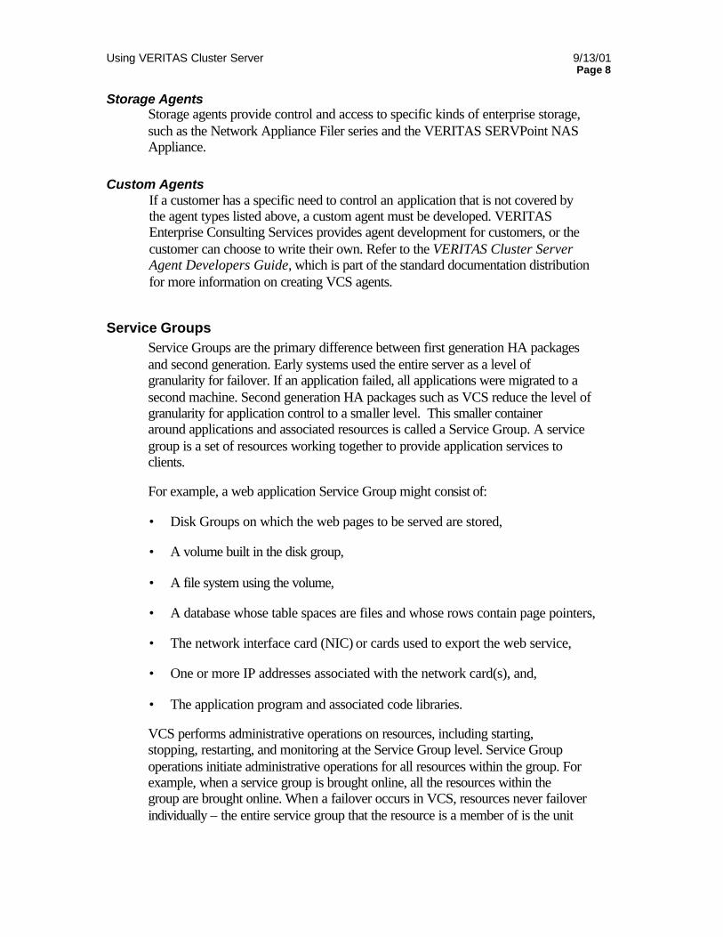
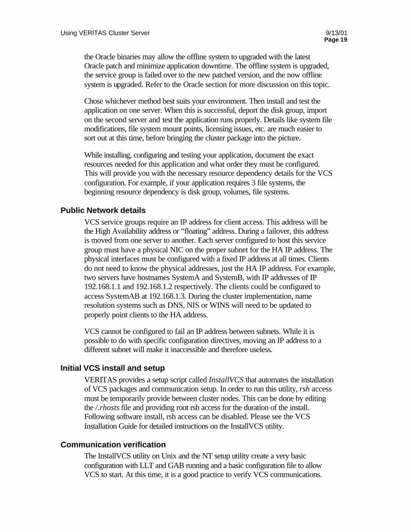
One of the most important parts of a service group definition is the concept of resource dependencies. As mentioned above, resource dependencies determine the order specific resources within a Service Group are brought online or offline when the Service Group is brought offline or online. For example, a VxVM Disk Group must be imported before volumes in the disk group can be started and volumes must start before file systems can be mounted. In the same manner, file systems must be unmounted before volumes are stopped and volumes stopped before disk groups deported. Diagramming resources and their dependencies forms a graph. In VCS terminology, resources are Parents or Children. Parent resources appear at the top of the arcs that connect them to their child resources. Typically, child resources are brought online before parent resources, and parent resources are taken offline before child resources. Resources must adhere to the established order of dependency. The dependency graph is common shorthand used to document resource dependencies within a Service Group. The illustration shows a resource dependency graph for a cluster service.
Using VERITAS Cluster Server 9/13/01 Page 10
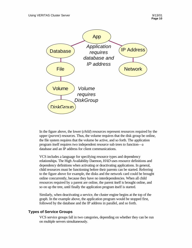
In the figure above, the lower (child) resources represent resources required by the upper (parent) resources. Thus, the volume requires that the disk group be online, the file system requires that the volume be active, and so forth. The application program itself requires two independent resource sub trees to function—a database and an IP address for client communications.
VCS includes a language for specifying resource types and dependency relationships. The High Availability Daemon, HAD uses resource definitions and dependency definitions when activating or deactivating applications. In general, child resources must be functioning before their parents can be started. Referring to the figure above for example, the disks and the network card could be brought online concurrently, because they have no interdependencies. When all child resources required by a parent are online, the parent itself is brought online, and so on up the tree, until finally the application program itself is started.
Similarly, when deactivating a service, the cluster engine begins at the top of the graph. In the example above, the application program would be stopped first, followed by the database and the IP address in parallel, and so forth.
Types of Service Groups VCS service groups fall in two categories, depending on whether they can be run on multiple servers simultaneously.
DiskGroup
Volume
File
Database
Network Card
IP Address
App
Volume requires
DiskGroup
Application requires
database and IP address
Using VERITAS Cluster Server 9/13/01 Page 11
Failover Groups A failover group runs on one system in the cluster at a time. Failover groups are used for most application services, such as most databases, NFS servers and any other application not designed to maintain data consistency when multiple copies are started.
The VCS engine assures that a service group is only online, partially online or in any states other than offline (such as attempting to go online or attempting to go offline).
Parallel Groups A parallel group can runs concurrently on more than one system in the cluster at a time.
A parallel service group is more complex than a failover group. It requires an application that can safely be started on more than one system at a time, with no threat of data corruption. This is explained “Managing Application Availability with VERITAS Cluster Server” under Horizontal Scaling.
In real world customer installations, parallel groups are used less than 1% of the time.
Cluster Communications (Heartbeat) VCS uses private network communications between cluster nodes for cluster maintenance. This communication takes the form of nodes informing other nodes they are alive, known as heartbeat, and nodes informing all other nodes of actions taking place and the status of all resources on a particular node, known as cluster status. This cluster communication takes place over a private, dedicated network between cluster nodes. VERITAS requires two completely independent, private networks between all cluster nodes to provide necessary communication path redundancy and allow VCS to discriminate between a network failure and a system failure.
VCS uses a purpose built communication package, comprised of the Low Latency Transport (LLT) and Group Membership/Atomic Broadcast (GAB). These packages function together as a replacement for the IP stack and provide a robust, high-speed communication link between systems without the latency induced by the normal network stack.
VCS communications are discussed in detail in the white paper “VCS Daemons and Communications”
Putting the pieces together. How do all these pieces tie together to form a cluster? Understanding this makes the rest of VCS fairly simple. Let’s take a very common example, a two-node cluster serving a single NFS file system to clients. The cluster itself consists of
Using VERITAS Cluster Server 9/13/01 Page 12
two nodes; connected to shared storage to allow both servers to access the data needed for the file system export.
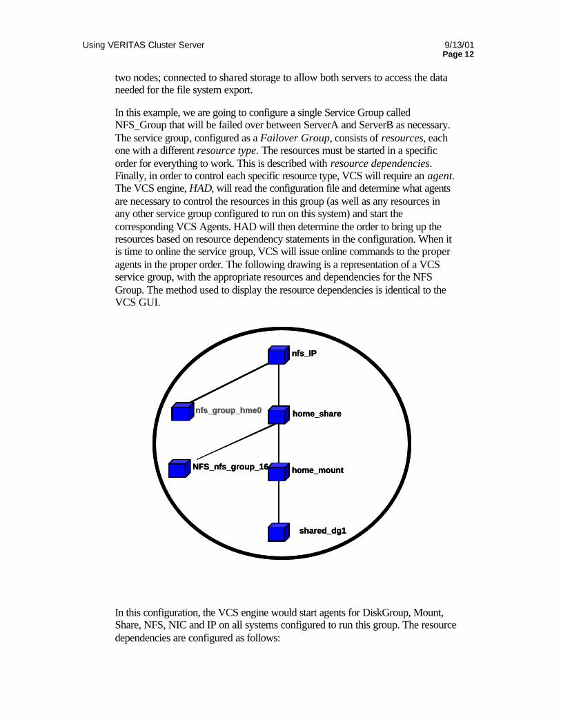
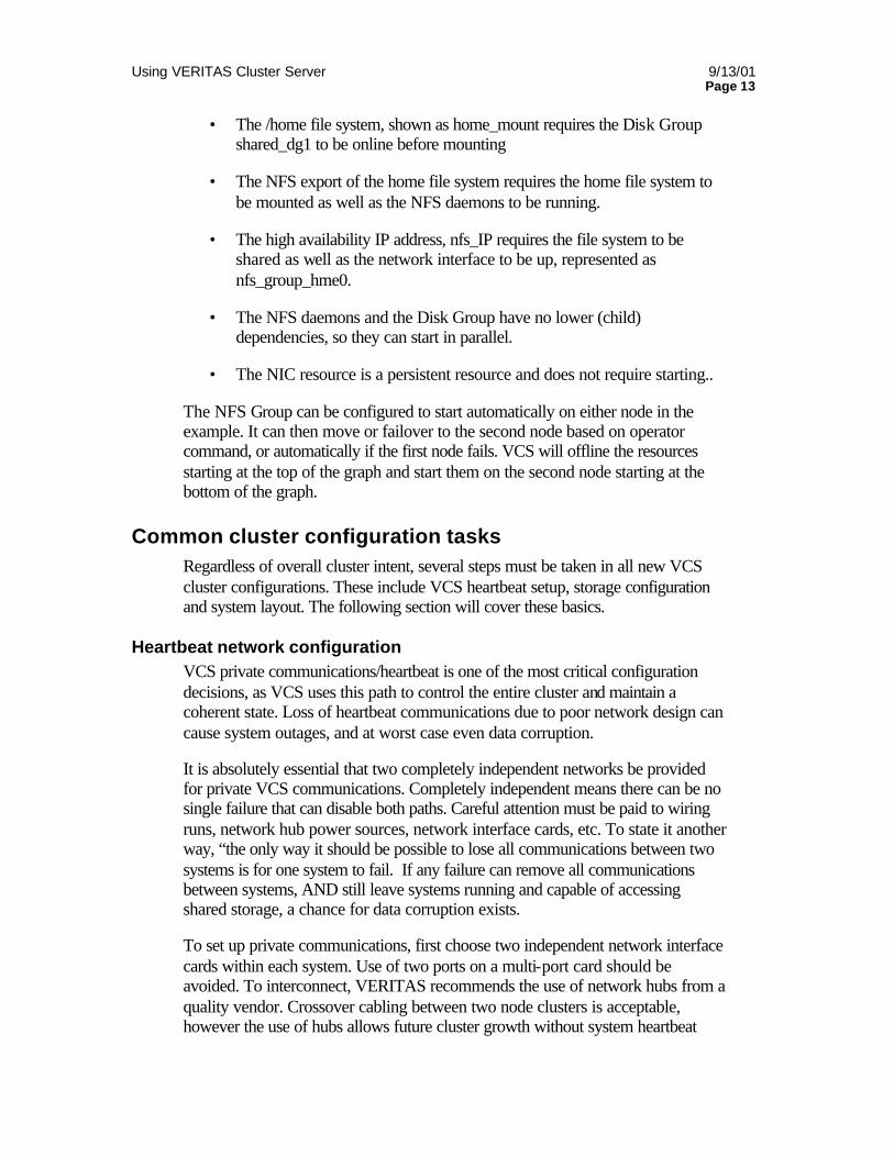
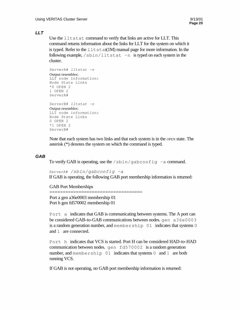
In this example, we are going to configure a single Service Group called NFS_Group that will be failed over between ServerA and ServerB as necessary. The service group, configured as a Failover Group, consists of resources, each one with a different resource type. The resources must be started in a specific order for everything to work. This is described with resource dependencies. Finally, in order to control each specific resource type, VCS will require an agent. The VCS engine, HAD, will read the configuration file and determine what agents are necessary to control the resources in this group (as well as any resources in any other service group configured to run on this system) and start the corresponding VCS Agents. HAD will then determine the order to bring up the resources based on resource dependency statements in the configuration. When it is time to online the service group, VCS will issue online commands to the proper agents in the proper order. The following drawing is a representation of a VCS service group, with the appropriate resources and dependencies for the NFS Group. The method used to display the resource dependencies is identical to the VCS GUI.
In this configuration, the VCS engine would start agents for DiskGroup, Mount, Share, NFS, NIC and IP on all systems configured to run this group. The resource dependencies are configured as follows:
nfs_IP
nfs_group_hme0
home_mount
shared_dg1
home_share
NFS_nfs_group_16
nfs_IPnfs_IP
nfs_group_hme0nfs_group_hme0
home_mounthome_mount
shared_dg1shared_dg1
home_sharehome_share
NFS_nfs_group_16NFS_nfs_group_16
Using VERITAS Cluster Server 9/13/01 Page 13
• The /home file system, shown as home_mount requires the Disk Group shared_dg1 to be online before mounting
• The NFS export of the home file system requires the home file system to be mounted as well as the NFS daemons to be running.
• The high availability IP address, nfs_IP requires the file system to be shared as well as the network interface to be up, represented as nfs_group_hme0.
• The NFS daemons and the Disk Group have no lower (child) dependencies, so they can start in parallel.
• The NIC resource is a persistent resource and does not require starting..
The NFS Group can be configured to start automatically on either node in the example. It can then move or failover to the second node based on operator command, or automatically if the first node fails. VCS will offline the resources starting at the top of the graph and start them on the second node starting at the bottom of the graph.
Common cluster configuration tasks Regardless of overall cluster intent, several steps must be taken in all new VCS cluster configurations. These include VCS heartbeat setup, storage configuration and system layout. The following section will cover these basics.
Heartbeat network configuration VCS private communications/heartbeat is one of the most critical configuration decisions, as VCS uses this path to control the entire cluster and maintain a coherent state. Loss of heartbeat communications due to poor network design can cause system outages, and at worst case even data corruption.
It is absolutely essential that two completely independent networks be provided for private VCS communications. Completely independent means there can be no single failure that can disable both paths. Careful attention must be paid to wiring runs, network hub power sources, network interface cards, etc. To state it another way, “the only way it should be possible to lose all communications between two systems is for one system to fail. If any failure can remove all communications between systems, AND still leave systems running and capable of accessing shared storage, a chance for data corruption exists.
To set up private communications, first choose two independent network interface cards within each system. Use of two ports on a multi-port card should be avoided. To interconnect, VERITAS recommends the use of network hubs from a quality vendor. Crossover cabling between two node clusters is acceptable, however the use of hubs allows future cluster growth without system heartbeat
Using VERITAS Cluster Server 9/13/01 Page 14
interruption of existing nodes. Next ensure the hubs are powered from separate power sources. In many cases, tying one hub to the power source for one server and the second hub to power for the second server provides adequate redundancy. Connect systems to the hubs with professionally built network cables, running on separate paths. Ensure a single wiring bundle or network patch panel problem cannot affect both cable runs.
Depending on operating system, ensure network interface speed and duplex settings are hard set and auto negotiation is disabled.
Test the network connections by temporarily assigning network addresses and use telnet or ping to verify communications. You must use different IP network addresses to ensure traffic actually uses the correct port. VERITAS also provides a layer-2 connectivity test called “dlpiping” that can be used to test network connectivity without configuring IP addresses.
The InstallVCS script (Solaris version 1.3 and above and HP version 1.3.1 Patch 3 and above) will configure actual VCS heartbeat at a later time. For manual VCS communication configuration, see the VCS Daemons and Communications white paper..
To add more robust heartbeat capabilities, in addition to the two private networks, additional heartbeat capability may be added on the customer public network (referred to as a “low priority” heartbeat) and over disk channels (referred to as “gabdisk”). These additional heartbeat capabilities are discussed in the VCS Daemons and Communications white paper.
Storage Configuration. As described in “Storage considerations” in Managing Application Availability with VERITAS Cluster Server, VCS is a designed as a “shared data” high availability product. In order to failover an application from one node to another, both nodes must have direct access to the data storage. This can be accomplished with dual hosted SCSI or a Storage Area Network. The use of replicated data instead of shared disk is only supported in very limited configurations and will not be discussed in this document.
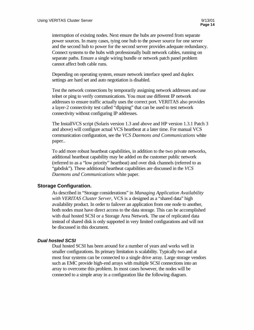
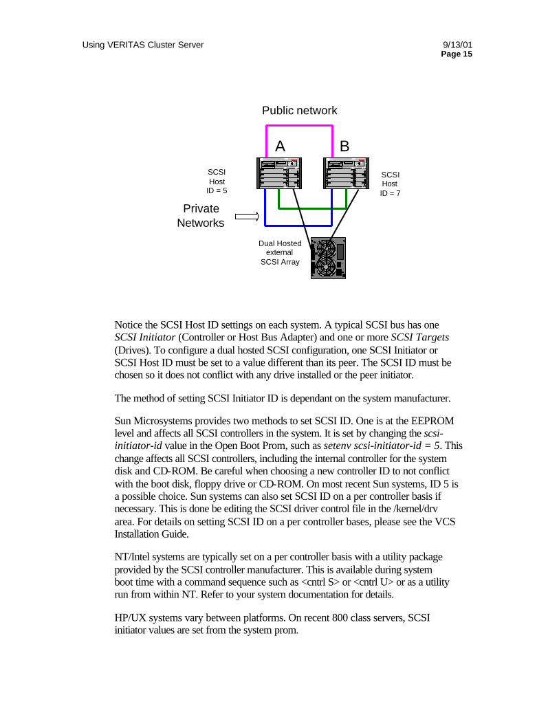
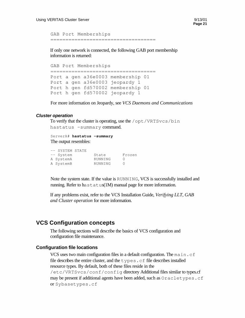
Dual hosted SCSI Dual hosted SCSI has been around for a number of years and works well in smaller configurations. Its primary limitation is scalability. Typically two and at most four systems can be connected to a single drive array. Large storage vendors such as EMC provide high-end arrays with multiple SCSI connections into an array to overcome this problem. In most cases however, the nodes will be connected to a simple array in a configuration like the following diagram.
Using VERITAS Cluster Server 9/13/01 Page 15
Notice the SCSI Host ID settings on each system. A typical SCSI bus has one SCSI Initiator (Controller or Host Bus Adapter) and one or more SCSI Targets (Drives). To configure a dual hosted SCSI configuration, one SCSI Initiator or SCSI Host ID must be set to a value different than its peer. The SCSI ID must be chosen so it does not conflict with any drive installed or the peer initiator.
The method of setting SCSI Initiator ID is dependant on the system manufacturer.
Sun Microsystems provides two methods to set SCSI ID. One is at the EEPROM level and affects all SCSI controllers in the system. It is set by changing the scsi-initiator-id value in the Open Boot Prom, such as setenv scsi-initiator-id = 5. This change affects all SCSI controllers, including the internal controller for the system disk and CD-ROM. Be careful when choosing a new controller ID to not conflict with the boot disk, floppy drive or CD-ROM. On most recent Sun systems, ID 5 is a possible choice. Sun systems can also set SCSI ID on a per controller basis if necessary. This is done be editing the SCSI driver control file in the /kernel/drv area. For details on setting SCSI ID on a per controller bases, please see the VCS Installation Guide.
NT/Intel systems are typically set on a per controller basis with a utility package provided by the SCSI controller manufacturer. This is available during system boot time with a command sequence such as <cntrl S> or <cntrl U> or as a utility run from within NT. Refer to your system documentation for details.
HP/UX systems vary between platforms. On recent 800 class servers, SCSI initiator values are set from the system prom.
PrivateNetworks
S D
Sun ENT ERP RI SE
Ω
Ω
Ω
4 0 0 0
S PA RCDR IV ENUL TR A
SD
Sun E NT E RPR I SE
Ω
Ω
Ω
4 0 0 0
S PAR CDR IVE NULT RA
A B
Public network
Dual Hostedexternal
SCSI Array
SCSIHost
ID = 5
SCSIHostID = 7
SD
IN
O U T
H IGH
L O
Using VERITAS Cluster Server 9/13/01 Page 16
The most common problem seen in configuring shared SCSI storage is duplicate SCSI Ids. A duplicate SCSI ID will, in many cases, exhibit different symptoms depending on whether there are duplicate controller Ids or a controller ID conflicting with a disk drive. A controller conflicting with a drive will often manifest itself as “phantom drives”. For example, on a Sun system with a drive ID conflict, the output of the format command will show 16 drives, ID 0-15 attached to the bus with the conflict. Duplicate controller Ids are a very serious problem, yet are harder to spot. SCSI controllers are also known as SCSI Initiators. An initiator, as the name implies, initiates commands. SCSI drives are targets. In a normal communication sequence, a target can only respond to a command from am initiator. If an initiator sees a command from an initiator, it will be ignored. The problem may only manifest itself during simultaneous commands from both initiators. A controller could issue a command, and see a response from a drive and assume all was well. This command may actually have been from the peer system. The original command may have not happened. Carefully examine systems attached to shared SCSI and make certain controller ID is different.
The following is an example of a typical shared SCSI configuration.
• Start with the storage attached to one system. Terminate the SCSI bus at the array.
• Power up the host system and array.
• Verify all drives can be seen with the operating system using available commands such as format or ioscan.
• Identify what SCSI drive ID’s are used in the array and internal SCSI drives if present.
• Identify the SCSI controller ID. On Sun systems, this is displayed at system boot. NT systems may require launching the SCSI configuration utility during system boot.
• Identify a suitable ID for the controller on the second system.
o This ID must not conflict with any drive in the array or the peer controller.
o If you plan to set all controllers to a new ID, as done from EEPROM on a Sun system, ensure the controller ID chosen on the second system does not conflict with internal SCSI devices.
• Set the new SCSI controller ID on the second system. It may be a good idea to test boot at this point.
Using VERITAS Cluster Server 9/13/01 Page 17
• Power down both systems and the external array. SCSI controllers or the array may be damaged if you attempt to “hot-plug” a SCSI cable. Disconnect the SCSI terminator and cable the array to the second system.
• Power up the array and both systems. Depending on hardware platform, you me be able to check for array connectivity before the operating system is brought up.
o On Sun systems, halt the boot process at the boot prom. Use the command probe-scsi-all to verify the disks can be seen from the hardware level on both systems. If this works, proceed with a boot –r to reconfigure the Solaris /dev entries.
o On NT systems, most SCSI adapters provide a utility available from the boot sequence. Entering the SCSI utility will allow you to view attached devices. Verify both systems can see the shared storage, verify SCSI controller ID one last time and then boot the systems.
• Boot console messages such as “unexpected SCSI reset” are a normal occurrence during the boot sequence of a system connected to a shared array. Most SCSI adapters will perform a bus reset during initialization. The error message is generated when it sees a reset it did not initiate (initiated by the peer).
Storage Area Networks Storage Area networks or SANs have dramatically increased configuration capability and scalability in cluster environments. The use of Fibre Channel fabric switches and loop hubs allow storage to be added with no electrical interruption to the host system as well as eliminates termination issues.
Configuration steps to build a VCS cluster on a SAN differ depending on SAN architecture.
Depending on system design, it is likely you will not be able to verify disk connectivity before system boot. It is not necessary to set initiator ID’s in a SAN environment.. Once the necessary Host Bus Adapters are installed and cabled, boot the systems and verify connectivity as outlined below.
Storage Configuration Sequence VCS requires the underlying operating system to be able to see and access shared storage. After installing the shared array, verify the drives can be seen from the operating system. In Solaris, the format command can be used. On HP, use the ioscan –C disk command, or simply ioscan
Once disk access is verified from the operating system, it is time to address cluster storage requirements. This will be determined by the application(s) that will be
Using VERITAS Cluster Server 9/13/01 Page 18
run in the cluster. The rest of this section assumes the installer will be using the VERITAS Volume Manager VxVM to control and allocate disk storage.
Recall the discussion on Service Groups. In this section it was stated that a service group must be completely self-contained, including storage resources. From a VxVM perspective, this means a Disk Group can only belong to one service group. Multiple service groups will require multiple Disk Groups. Volumes may not be created in the VxVM rootdg for use in VCS, as rootdg cannot be deported and imported by the second server.
Determine the number of Disk Groups needed as well as the number and size of volumes in each disk group. Do not compromise disk protection afforded by disk mirroring or RAID to achieve the storage sizes needed. Buy more disks if necessary!
Perform all VxVM configuration tasks from one server. It is not necessary to perform any volume configuration on the second server, as all volume configuration data is stored within the volume itself. Working from one server will significantly decrease chances of errors during configuration.
Create required file systems on the volumes. On Unix systems, the use of journeled file systems is highly recommended (VxFS or Online JFS) to minimize recovery time after a system crash. On NT systems, utilize the NTFS file system. Do not configure file systems to automatically mount at boot time. This is the responsibility of VCS. Test access to the new file systems.
On the second server, create all necessary file system mount points to mirror the first server. At this point, it is recommended the VxVM disk groups be deported from the first server and imported on the second server and files systems test mounted.
Application setup One of the primary difficulties new VCS users encounters is “trying to get applications to work in VCS”. Very rarely is the trouble with VCS, but rather the application itself. VCS has the capability to start, stop and monitor individual resources. It does not have any magic hidden powers to start applications. Stated simply, “if the application can not be started from the command line, VCS will not be able to start it”. Understanding this is the key to simple VCS deployments. Manually testing that an application can be started and stopped on both systems before VCS is involved will save lots of time and frustration.
Another common question concerns application install locations. For example, in a simple two-node Oracle configuration, should the Oracle binaries be installed on the shared storage or locally on each system? Both methods have benefits. Installing application binaries on shared storage can provide simpler administration. Only one copy must be maintained, updated, etc. Installing separate copies also has its strong points. For example, installing local copies of
Using VERITAS Cluster Server 9/13/01 Page 19
the Oracle binaries may allow the offline system to upgraded with the latest Oracle patch and minimize application downtime. The offline system is upgraded, the service group is failed over to the new patched version, and the now offline system is upgraded. Refer to the Oracle section for more discussion on this topic.
Chose whichever method best suits your environment. Then install and test the application on one server. When this is successful, deport the disk group, import on the second server and test the application runs properly. Details like system file modifications, file system mount points, licensing issues, etc. are much easier to sort out at this time, before bringing the cluster package into the picture.
While installing, configuring and testing your application, document the exact resources needed for this application and what order they must be configured. This will provide you with the necessary resource dependency details for the VCS configuration. For example, if your application requires 3 file systems, the beginning resource dependency is disk group, volumes, file systems.
Public Network details VCS service groups require an IP address for client access. This address will be the High Availability address or “floating” address. During a failover, this address is moved from one server to another. Each server configured to host this service group must have a physical NIC on the proper subnet for the HA IP address. The physical interfaces must be configured with a fixed IP address at all times. Clients do not need to know the physical addresses, just the HA IP address. For example, two servers have hostnames SystemA and SystemB, with IP addresses of IP 192.168.1.1 and 192.168.1.2 respectively. The clients could be configured to access SystemAB at 192.168.1.3. During the cluster implementation, name resolution systems such as DNS, NIS or WINS will need to be updated to properly point clients to the HA address.
VCS cannot be configured to fail an IP address between subnets. While it is possible to do with specific configuration directives, moving an IP address to a different subnet will make it inaccessible and therefore useless.
Initial VCS install and setup VERITAS provides a setup script called InstallVCS that automates the installation of VCS packages and communication setup. In order to run this utility, rsh access must be temporarily provide between cluster nodes. This can be done by editing the /.rhosts file and providing root rsh access for the duration of the install. Following software install, rsh access can be disabled. Please see the VCS Installation Guide for detailed instructions on the InstallVCS utility.
Communication verification The InstallVCS utility on Unix and the NT setup utility create a very basic configuration with LLT and GAB running and a basic configuration file to allow VCS to start. At this time, it is a good practice to verify VCS communications.
Using VERITAS Cluster Server 9/13/01 Page 20
LLT Use the lltstat command to verify that links are active for LLT. This command returns information about the links for LLT for the system on which it is typed. Refer to the lltstat(1M) manual page for more information. In the following example, /sbin/lltstat –n is typed on each system in the cluster.
ServerA# lltstat –n Output resembles: LLT node information: Node State Links *0 OPEN 2 1 OPEN 2 ServerA#
ServerB# lltstat -n Output resembles: LLT node information: Node State Links 0 OPEN 2 *1 OPEN 2 ServerB#
Note that each system has two links and that each system is in the OPEN state. The asterisk (*) denotes the system on which the command is typed.
GAB To verify GAB is operating, use the /sbin/gabconfig –a command.
ServerA# /sbin/gabconfig -a If GAB is operating, the following GAB port membership information is returned:
GAB Port Memberships =================================== Port a gen a36e0003 membership 01 Port h gen fd570002 membership 01 Port a indicates that GAB is communicating between systems. The A port can be considered GAB-to-GAB communications between nodes. gen a36e0003 is a random generation number, and membership 01 indicates that systems 0 and 1 are connected.
Port h indicates that VCS is started. Port H can be considered HAD-to-HAD communication between nodes. gen fd570002 is a random generation number, and membership 01 indicates that systems 0 and 1 are both running VCS.
If GAB is not operating, no GAB port membership information is returned:
Using VERITAS Cluster Server 9/13/01 Page 21
GAB Port Memberships =================================== If only one network is connected, the following GAB port membership information is returned:
GAB Port Memberships =================================== Port a gen a36e0003 membership 01 Port a gen a36e0003 jeopardy 1 Port h gen fd570002 membership 01 Port h gen fd570002 jeopardy 1
For more information on Jeopardy, see VCS Daemons and Communications
Cluster operation To verify that the cluster is operating, use the /opt/VRTSvcs/bin hastatus –summary command.
ServerA# hastatus -summary The output resembles:
-- SYSTEM STATE -- System State Frozen A SystemA RUNNING 0 A SystemB RUNNING 0
Note the system state. If the value is RUNNING, VCS is successfully installed and running. Refer to hastatus(1M) manual page for more information.
If any problems exist, refer to the VCS Installation Guide, Verifying LLT, GAB and Cluster operation for more information.
VCS Configuration concepts The following sections will describe the basics of VCS configuration and configuration file maintenance.
Configuration file locations VCS uses two main configuration files in a default configuration. The main.cf file describes the entire cluster, and the types.cf file describes installed resource types. By default, both of these files reside in the /etc/VRTSvcs/conf/config directory Additional files similar to types.cf may be present if additional agents have been added, such as Oracletypes.cf or Sybasetypes.cf
Using VERITAS Cluster Server 9/13/01 Page 22
Main.cf file contents The main.cf file is the single file used to define an individual cluster. The overall format of the main.cf file is as follows:
• Include clauses Include clauses are used to bring in resource definitions. At a minimum, the types.cf file is included. Other type definitions must be configured as necessary. Typically, the addition of VERITAS VCS Enterprise Agents will add additional type definitions in their own files, as well as custom agents developed for this cluster. Most customers and VERITAS consultants will not modify the provided types.cf file, but instead create additional type files.
• Cluster definition The cluster section describes the overall attributes of the cluster. This includes:
• Cluster name • Cluster GUI users
• System definitions Each system designated as part of the cluster is listed in this section. The names listed as system names must match the name returned by the uname –a command in Unix. If fully qualified domain names are used, an additional file, /etc/VRTSvcs/conf/sysname must be created. See the VCS Installation Guide for more information on the use of the sysname file. System names are preceded with the keyword “system”. For any system to be used in a later service group definition, it must be defined here! Think of this as the overall set of systems available, with each service group being a subset.
• snmp definition (see Enabling SNNP Traps for more information) • Service group definitions
The service group definition is the overall attributes of this particular service group. Possible attributes for a service group are: (See the VCS users Guide for a complete list of Service Group Attributes)
• SystemList o List all systems that can run this service group. VCS will not
allow a service group to be onlined on any system not in the group’s system list. The order of systems in the list defines, by default, the priority of systems used in a failover. For example, SystemList = ServerA, ServerB, ServerC would configure sysa to be the first choice on failover, followed by sysb and so on. System priority may also be assigned explicitly in the SystemList by assigning numeric values to each system name. For example: SystemList = ServerA=0, ServerB=1, ServerC=2 is identical to the preceding example. But in this case, the administrator could change priority by changing the numeric priority values. Also note the different formatting of the “” characters. This is detailed later in this section under “Attributes.”
Using VERITAS Cluster Server 9/13/01 Page 23
• AutoStartList o The AutoStartList defines the system that should bring up the
group on a full cluster start. If this system is not up when all others are brought online, the service group will remain off line. For example: AutoStartList = ServerA .
• Resource definitions
This section will define each resource used in this service group. (And only this service group). Resources can be added in any order and hacf will reorder in alphabetical order the first time the config file is run.
• Service group dependency clauses To configure a service group dependency, place the keyword requires clause in the service group declaration within the VCS configuration file, before the resource dependency specifications, and after the resource declarations.
• Resource dependency clauses A dependency between resources is indicated by the keyword requires between two resource names. This indicates that the second resource (the child) must be online before the first resource (the parent) can be brought online. Conversely, the parent must be offline before the child can be taken offline. Also, faults of the children are propagated to the parent. This is the most common resource dependency
Sample Initial configuration When VCS is installed with the InstallVCS utility, there is a very basic main.cf created with the cluster name, systems in the cluster and a GUI user “admin” with the password “password”.
The following is an example of the main.cf for cluster “demo” and systems “SystemA” and “SystemB”
include "types.cf"
cluster demo (
UserNames = admin = cDRpdxPmHpzS
)
system SystemA system SystemB
Sample Two node asymmetric NFS cluster The following section will walk through a basic two-node cluster exporting an NFS file system. The systems are configured as follows:
• Servers: ServerA and ServerB
Using VERITAS Cluster Server 9/13/01 Page 24
• Storage: One VxVM disk group, shared1
• File System: /home
• IP address: 192.168.1.3 IP_nfs1
• Public interface: hme0
• ServerA is primary location to start the NFS_group1
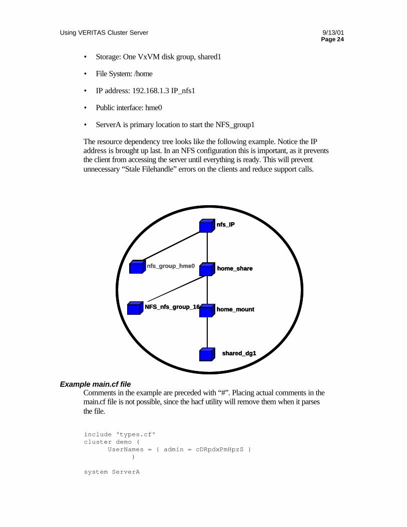
The resource dependency tree looks like the following example. Notice the IP address is brought up last. In an NFS configuration this is important, as it prevents the client from accessing the server until everything is ready. This will prevent unnecessary “Stale Filehandle” errors on the clients and reduce support calls.
Example main.cf file Comments in the example are preceded with “#”. Placing actual comments in the main.cf file is not possible, since the hacf utility will remove them when it parses the file.
include "types.cf" cluster demo ( UserNames = admin = cDRpdxPmHpzS
) system ServerA
nfs_IP
nfs_group_hme0
home_mount
shared_dg1
home_share
NFS_nfs_group_16
nfs_IPnfs_IP
nfs_group_hme0nfs_group_hme0
home_mounthome_mount
shared_dg1shared_dg1
home_sharehome_share
NFS_nfs_group_16NFS_nfs_group_16
Using VERITAS Cluster Server 9/13/01 Page 25
system ServerB snmp vcs # The following section will describe the NFS group. This group # definition runs till end of file or till next instance of the # keyword group group NFS_group1 ( SystemList = ServerA, ServerB AutoStartList = ServerA ) DiskGroup DG_shared1 ( DiskGroup = shared1 ) IP IP_nfs1 ( Device = hme0 Address = "192.168.1.3" ) Mount Mount_home ( MountPoint = "/export/home" BlockDevice = "/dev/vx/dsk/shared1/home_vol" FSType = vxfs MountOpt = rw ) NFS NFS_group1_16 ( Nservers = 16
) NIC NIC_group1_hme0 ( Device = hme0 NetworkType = ether ) Share Share_home ( PathName = "/export/home" ) IP_nfs1 requires Share_home IP_nfs1 requires NIC_group1_hme0 Mount_home requires DG_shared1 Share_home requires NFS_group1_16 Share_home requires Mount_home .
Resource type definitions The types.cf file describes standard resource types to the VCS engine. The file describes the data necessary to control a given resource. The following is an example of the DiskGroup resource type definition.
Using VERITAS Cluster Server 9/13/01 Page 26
type DiskGroup ( static int NumThreads = 1 static int OnlineRetryLimit = 1 static str ArgList[] = DiskGroup, StartVolumes, StopVolumes, MonitorOnly NameRule = resource.DiskGroup str DiskGroup str StartVolumes = 1 str StopVolumes = 1
The types definition performs two very important functions. First it defines the sort of values that may be set for each attribute. In the DiskGroup example, the NumThreads and OnlineRetryLimit are both classified as int, or integer. Signed integer constants are a sequence of digits from 0 to 9. They may be preceded by a dash, and are interpreted in base 10.
The DiskGroup, StartVolumes and StopVolumes are strings. As described in the Users Guide: A string is a sequence of characters enclosed by double quotes. A string may also contain double quotes, but the quotes must be immediately preceded by a backslash. A backslash is represented in a string as \\. Quotes are not required if a string begins with a letter, and contains only letters, numbers, dashes (-), and underscores (_).
The second critical piece of information provided by the type definition is the “ArgList”. The line “static str ArgList [] = xxx, yyy, zzz defines the order that parameters are passed to the agents for starting, stopping and monitoring resources. For example, when VCS wishes to online the disk group “shared_dg1”, it passes the online command to the DiskGroupAgent with the following arguments (shared_dg1 shared_dg1 1 1 <null>). This is the online command, the name of the resource, then the contents of the ArgList. Since MonitorOnly is not set, it is passed as a null. This is always the case: command, resource name, ArgList.
For another example, look at the following main.cf and types.cf pair representing an IP resource:
IP nfs_ip1 ( Device = hme0 Address = "192.168.1.201" )
type IP ( static str ArgList[] = Device, Address, NetMask, Options, ArpDelay, IfconfigTwice NameRule = IP_ + resource.Address str Device str Address str NetMask str Options int ArpDelay = 1 int IfconfigTwice )
Using VERITAS Cluster Server 9/13/01 Page 27
In this example, we configure the high availability address on interface hme0. Notice the double quotes around the IP address. The string contains periods and therefore must be quoted. The arguments passed to the IPAgent with the online command (nfs_ip1 hme0 192.168.1.201 <null> <null> 1 <null>).
The VCS engine passes the identical arguments to the IPAgent for online, offline, clean and monitor. It is up to the agent to use the arguments that it needs. This is a very key concept to understand later in the custom agent section.
All resource names must be unique in a VCS cluster. If a name is not specified, the hacf utility will generate a unique name based on the “NameRule” The NameRule for the above example would provide a name of “IP_192.168.1.201”
For more information on creating custom resource type definitions as well as custom agents, see the VCS Custom Agents white paper.
Attributes VCS components are configured using “attributes”. Attributes contain data regarding the cluster, systems, service groups, resources, resource types, and agents. For example, the value of a service group’s SystemList attribute specifies on which systems the group is configured, and the priority of each system within the group. Each attribute has a definition and a value. You define an attribute by specifying its data type and dimension. Attributes also have default values that are assigned when a value is not specified.
Data Type Description
String A string is a sequence of characters enclosed by double quotes. A string may also contain double quotes, but the quotes must be immediately preceded by a backslash. A backslash is represented in a string as \\. Quotes are not required if a string begins with a letter, and contains only letters, numbers, dashes (-), and underscores (_). For example, a string defining a network interface such as hme0 does not require quotes as it contains only letters and numbers. However a string defining an IP address requires quotes, such as: “192.168.100.1” since the IP contains periods.
Integer Signed integer constants are a sequence of digits from 0 to 9. They may be preceded by a dash, and are interpreted in base 10. In the example above, the number of times to retry the online operation of a DiskGroup is defined with an integer:
Using VERITAS Cluster Server 9/13/01 Page 28
an integer:
static int OnlineRetryLimit = 1
Boolean A boolean is an integer, the possible values of which are 0 (false) and 1 (true). From the main.cf example above, SNMP is enabled by setting the Enabled attribute to 1 as follows:
Enabled = 1
Dimension Description
Scalar A scalar has only one value. This is the default dimension.
Vector A vector is an ordered list of values. Each value is indexed using a positive integer beginning with zero. A set of brackets ([]) denotes that the dimension is a vector. Brackets are specified after the attribute name on the attribute definition. For example, to designate a dependency between resource types specified in the service group list, and all instances of the respective resource type: Dependencies[] = Mount, Disk, DiskGroup
Keylist A keylist is an unordered list of strings, and each string is unique within the list. For example, to designate the list of systems on which a service group will be started with VCS (usually at system boot): AutoStartList = sysa, sysb, sysc
Association An association is an unordered list of name-value pairs. Each pair is separated by an equal sign. A set of braces () denotes that an attribute is an association. Braces are specified after the attribute name on the attribute definition. For example, to designate the list of systems on which the service group is configured to run and the system’s priorities: SystemList() = sysa=1, sysb=2, sysc=3
Type dependant attributes Type dependant attributes are those attributes, which pertain to a particular resource type. For example the “BlockDevice” attribute is only relevant to the
Using VERITAS Cluster Server 9/13/01 Page 29
Mount resource type. Similarly, the IPAddress attribute pertains to the IP resource type.
Type independent attributes Type independent attributes are attributes that apply to all resource types. This means there is a set of attributes that all agents can understand, regardless of resource type. These attributes are coded into the agent framework when the agent is developed. Attributes such as RestartLimit and MonitorInterval can be set for any resource type. These type independent attributes must still be set on a per resource type basis, but the agent will understand the values and know how to use them.
Resource specific attributes Resource specific attributes are those attributes, which pertain to a given resource only. These are discrete values that define the “personality” of a given resource. For example, the IPAgent knows how to use an IPAddress attribute. Actually setting an IP address is only done within a specific resource definition. Resource specific attributes are set in the main.cf file
Type specific attributes Type specific attributes refer to attributes, which are set for all resources of a specific type. For example, setting MonitorInterval for the IP resource affects all IP resources. This value would be placed in the types.cf file. In some cases, attributes can be placed in either location. For example, setting “StartVolumes = 1” in the DiskGroup types.cf entry would default StartVolumes to true for all DiskGroup resources. Placing the value in main.cf would set StartVolumes on a per resource value
In the following examples of types.cf entries, we will document several methods to set type specific attributes.
In the example below, StartVolumes and StopVolumes is set in types.cf. This sets the default for all DiskGroup resources to automatically start all volumes contained in a disk group when the disk group is onlined. This is simply a default. If no value for StartVolumes or StopVolumes is set in main.cf, it will they will default to true.
type DiskGroup ( static int NumThreads = 1 static int OnlineRetryLimit = 1 static str ArgList[] = DiskGroup, StartVolumes, StopVolumes, MonitorOnly NameRule = resource.DiskGroup str DiskGroup str StartVolumes = 1 str StopVolumes = 1
Using VERITAS Cluster Server 9/13/01 Page 30
Adding the required lines in main.cf will allow this value to be overridden. In the next excerpt, the main.cf is used to override the default type specific attribute with a resource specific attribute
DiskGroup shared_dg1 ( DiskGroup = shared_dg1 StartVolumes = 0 StopVolumes = 0 )
In the next example, changing the StartVolumes and StopVolumes attributes to static str disables main.cf from overriding.
type DiskGroup ( static int NumThreads = 1 static int OnlineRetryLimit = 1 static str ArgList[] = DiskGroup, StartVolumes, StopVolumes, MonitorOnly NameRule = resource.DiskGroup str DiskGroup static str StartVolumes = 1 static str StopVolumes = 1
Local and Global attributes An attribute whose value applies to all systems is global in scope. An attribute whose value applies on a per-system basis is local in scope. The “at” operator (@) indicates the system to which a local value applies. An example of local attributes can be found in the MultiNICA resource type where IP addresses and routing options are assigned on a per machine basis.
MultiNICA mnic ( Device@sysa = le0 = "166.98.16.103", qfe3 = "166.98.16.103" Device@sysb = le0 = "166.98.16.104", qfe3 = "166.98.16.104" NetMask = "255.255.255.0" ArpDelay = 5 Options = "trailers" RouteOptions@sysa = "default 166.98.16.103 0" RouteOptions@sysb = "default 166.98.16.104 0" )
Modifying the Configuration VCS offers three ways to modify an existing configuration. These can be grouped as “online” and “offline”, depending on whether VCS is up during the modification or not. When VCS initials starts up, it reads in a configuration from disk when it starts up and all other systems build from this “in-memory” copy. This means that editing the configuration file on disk does not affect the running cluster. Please carefully review the next section of Configuration File Replication
Using VERITAS Cluster Server 9/13/01 Page 31
Modifying the main.cf file Modifying the main.cf file with a text editor is probably the overall easiest method to make large changes or additions to the cluster. Entire group definitions can be copied and pasted and modified at the administrator’s leisure. The downside is the cluster must be stopped and restarted to make the changes take effect. The required changes can be made while the cluster is operational, then briefly stopped and restarted at a low impact time. One item to note, VCS writes out any necessary changes to the running main.cf to the on disk version when it exits, so it is best to copy the copy you wish to modify to another name. For example, copy main.cf to /var/tmp/main.cf. Then make all necessary edits to this file. When you are complete, verify the file by running hacf –verify /var/tmp. The cluster can then be stopped and the /var/tmp/main.cf copied to /etc/VRTSvcs/conf/config directory and the cluster restarted on this node.
One other possible method here is to use the hastop –force –all command to stop the cluster and leave applications running. The cluster can then be restarted to read in the new configuration.
Modifying the configuration from the command line Modifying the VCS configuration is done while the cluster is online (it is not possible to modify the cluster when the cluster is stopped, of HAD is stopped on the node you are working from).
Modifications are done with standard VCS command line interface (CLI) commands. These commands are documented in the VCS users Guide under “Administering VCS from the Command Line”.
Please see the “Sample NFS Configuration “ for an example of adding a Service Group from the command line.
Modifying the configuration using the GUI The VCS GUI provides a very powerful, easy to use method to control and maintain your cluster. Please see the VCS Users Guide, “About the VCS GUI” for more information on creating GUI users, adding VCS clusters to the Cluster Monitor configuration and using the VCS GUI.
Adding SNMP traps VCS inserts SNMP trap information in the main.cf file the first time the configuration is saved. To enable traps to be sent to a SNMP monitor console, the monitor console IP and port must be configured and SNMP enabled. The following main.cf example shows an enabled SNMP configuration
snmp vcs ( Enabled = 1 IPAddr = “192.168.1.101” Port = 100
Using VERITAS Cluster Server 9/13/01 Page 32
TrapList = 1 = "A new system has joined the VCS Cluster", 2 = "An existing system has changed its state", 3 = "A service group has changed its state", 4 = "One or more heartbeat links has gone down", 5 = "An HA service has done a manual restart", 6 = "An HA service has been manually idled", 7 = "An HA service has been successfully started" )
Using Proxy Resources A proxy resource allows a resource configured and monitored in a separate service group to be mirrored in a service group. This is provided for two reasons:
• Reduce monitoring overhead. Configuring multiple resources pointing at the same physical device adds unnecessary monitoring overhead. For example, if multiple service groups use the same NIC device, all configured resources would monitor the same NIC. Using a proxy resource allows one Service group to monitor the NIC and this status is mirrored to the proxy resource.
• Determine status of an OnOff Resource in a different Service Group. VCS OnOff resources may only exist on one Service Group in a Failover group configuration.
Examples of using a proxy resource follow in the NFS example.
Configuration File Replication VCS uses a replicated configuration file to eliminate any single point of failure. The cluster engine is responsible for distributing the current copy of the configuration to all running members as well as any new joining members.
From a high level, when a node starts up, it checks if any other node is already up and running. If so, it will obtain the configuration from the running node. If not, and the starting node has a valid configuration copy, it will build from its local copy. Any node starting after would then build from this node. When a node shuts down, it automatically writes the current running configuration out to disk.
The VCS configuration replication process is a very powerful tool for maintaining large clusters. However, it does require some additional knowledge to properly work with the cluster engine during configuration modification.
The following sections will detail the VCS startup and shutdown process and all possible state transitions during each process.
VCS startup The following diagram shows the possible state transitions when VCS starts up.
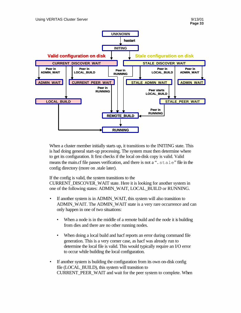
Using VERITAS Cluster Server 9/13/01 Page 33
When a cluster member initially starts up, it transitions to the INITING state. This is had doing general start-up processing. The system must then determine where to get its configuration. It first checks if the local on-disk copy is valid. Valid means the main.cf file passes verification, and there is not a “.stale” file in the config directory (more on .stale later).
If the config is valid, the system transitions to the CURRENT_DISCOVER_WAIT state. Here it is looking for another system in one of the following states: ADMIN_WAIT, LOCAL_BUILD or RUNNING.
• If another system is in ADMIN_WAIT, this system will also transition to ADMIN_WAIT. The ADMIN_WAIT state is a very rare occurrence and can only happen in one of two situations:
• When a node is in the middle of a remote build and the node it is building from dies and there are no other running nodes.
• When doing a local build and hacf reports an error during command file generation. This is a very corner case, as hacf was already run to determine the local file is valid. This would typically require an I/O error to occur while building the local configuration.
• If another system is building the configuration from its own on-disk config file (LOCAL_BUILD), this system will transition to CURRENT_PEER_WAIT and wait for the peer system to complete. When
UNKNOWN
CURRENT_DISCOVER_WAIT STALE_DISCOVER_WAIT
ADMIN_WAIT ADMIN_WAIT
LOCAL_BUILD
CURRENT_PEER_WAIT
STALE_PEER_WAIT
STALE_ADMIN_WAIT
REMOTE_BUILD
RUNNING
Peer in LOCAL_BUILD
Peer inRUNNING
Peer inRUNNING
Peer inLOCAL_BUILD
Peer inADMIN_WAIT
Peer inADMIN_WAIT
Valid configuration on disk Stale configuration on disk
hastart
Peer startsLOCAL_BUILD
INITING
Peer inRUNNING
Using VERITAS Cluster Server 9/13/01 Page 34
the peer transitions to RUNNING, this system will do a REMOTE_BUILD to get the configuration from the peer.
• If another system is already in RUNNING state, this system will do a REMOTE_BUILD and get the configuration from the peer.
If no other systems are in any of the 3 states listed above, this system will transition to LOCAL_BUILD and generate the cluster config from its own on disk config file. Other systems coming up after this point will do REMOTE_BUILD.
If the system comes up and determines the local configuration is not valid, i.e. does not pass verification or has a “.stale” file, the system will shift to STALE_DISCOVER_WAIT. The system then looks for other systems in the following states: ADMIN_WAIT, LOCAL_BUILD or RUNNING.
• If another system is in ADMIN_WAIT, this system will also transition to ADMIN_WAIT
• If another system is building the configuration from its own on-disk config file (LOCAL_BUILD), this system will transition to STALE_PEER_WAIT and wait for the peer system to complete. When the peer transitions to RUNNING, this system will do a REMOTE_BUILD to get the configuration from the peer.
• If another system is already in RUNNING state, this system will do a REMOTE_BUILD and get the configuration from the peer.
If no other system is in any of the three states above, this system will transition to STALE_ADMIN_WAIT. It will remain in this state until another peer comes up with a valid config file and does a LOCAL_BUILD. This system will then transition to STALE_PEER_WAIT, wait for the peer to finish, then transition to REMOTE_BUILD and finally RUNNING.
VCS Shutdown The following diagram shows the possible state transitions on a VCS shutdown.
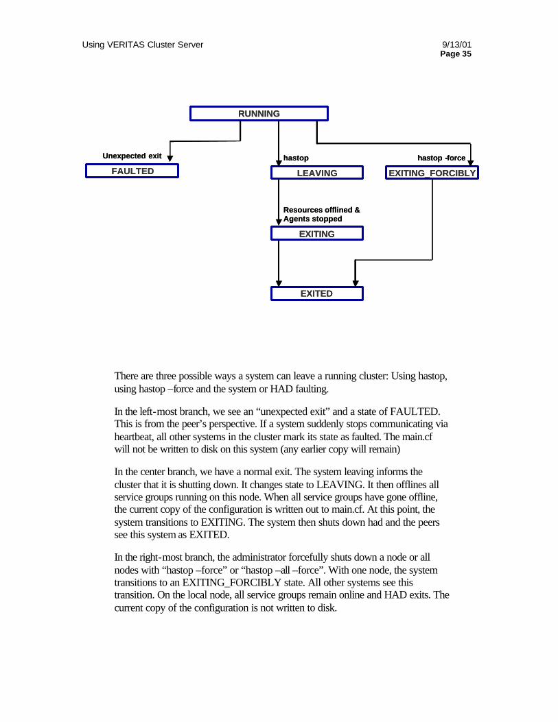
Using VERITAS Cluster Server 9/13/01 Page 35
There are three possible ways a system can leave a running cluster: Using hastop, using hastop –force and the system or HAD faulting.
In the left-most branch, we see an “unexpected exit” and a state of FAULTED. This is from the peer’s perspective. If a system suddenly stops communicating via heartbeat, all other systems in the cluster mark its state as faulted. The main.cf will not be written to disk on this system (any earlier copy will remain)
In the center branch, we have a normal exit. The system leaving informs the cluster that it is shutting down. It changes state to LEAVING. It then offlines all service groups running on this node. When all service groups have gone offline, the current copy of the configuration is written out to main.cf. At this point, the system transitions to EXITING. The system then shuts down had and the peers see this system as EXITED.
In the right-most branch, the administrator forcefully shuts down a node or all nodes with “hastop –force” or “hastop –all –force”. With one node, the system transitions to an EXITING_FORCIBLY state. All other systems see this transition. On the local node, all service groups remain online and HAD exits. The current copy of the configuration is not written to disk.
RUNNING
LEAVING
EXITING
EXITED
EXITING_FORCIBLYFAULTED
hastop hastop -force
Resources offlined &Agents stopped
Unexpected exit
RUNNING
LEAVING
EXITING
EXITED
EXITING_FORCIBLYFAULTED
hastop hastop -force
Resources offlined &Agents stopped
Unexpected exit
Using VERITAS Cluster Server 9/13/01 Page 36
Stale configurations There are several instances where VCS will come up in a stale state. The first is having a configuration file that is not valid. If running hacf –verify produces any errors, the file is not valid. The second is opening the configuration for writing while VCS is running with the GUI or by the command hacf –makerw. When the config is opened, VCS writes a .stale file to the config directory on each system. The .stale is removed when the file is once again read-only (Closed with the GUI or with the command hacf –makero –dump). If a system is shutdown with the configuration open, the .stale file will remain. Note: VCS 1.3 and above warns the user when attempting to stop the cluster with the configuration file open for writing.
VCS can ignore the .stale problem by starting had with “hastart –force”. You must first verify the local main.cf is actually correct for the cluster configuration.
Working examples The following examples will clarify the process of main.cf file replication and state startup issues.
The examples will use the two-node cluster described earlier, called “demo”. The two systems are ServerA and ServerB.
In the first example, the administrator starts with both systems running, with HAD stopped on both nodes. The main.cf is modified on SystemA to add new resources. The user will then start HAD on SystemA. HAD will enter the initing state. After initialization, it will determine if its local copy of main.cf is valid. If the administrator performed a verification of the main.cf file as detailed in the next section, it should be valid. SystemA will also look for .stale file in the config directory. If the file is valid, and no .stale exists, the engine will then look for another running system to build from. Since SystemA is the only running system, it will build from the local config file and transition to running. SystemB can then be started. It will perform the same set of checks, then build from SystemA. SystemB writes a copy of the configuration obtained from SystemA when HAD is stopped or the user explicitly dumps the configuration with the haconf –dump command (see Modifying the Configuration). If the node were to crash or lose power prior to this event, the configuration will not be written to disk. This is only a problem if SystemA were also to lose power. In this scenario, SystemA and SystemB both have a valid configuration, however SystemA has a more up to date configuration. If SystemB were allowed to come up first, followed by SystemA, the older configuration on SystemB would be used. To prevent this, always dump the running configuration after it is loaded and validated the first time.
For the next example, we will use the same cluster. In this case, the cluster is now up and running and the user opens the cluster configuration for writing with the command line or the GUI. This will write a .stale file to all systems running in the cluster. The .stale is not removed until the cluster configuration is closed and
Using VERITAS Cluster Server 9/13/01 Page 37
written out to disk. If the cluster crashes or powers off (or is forcibly stopped) before the .stale is removed, it will cause a STALE_ADMIN_WAIT condition the next time the cluster is started. This is to tell the administrator that changes in progress were not completed before the cluster was stopped. When the cluster comes up in STALE_ADMIN_WAIT, the administrator needs to check to main.cf file to determine if any changes are required. Then verify the config file and start the node in work with hastart –force.
A third example highlights a common problem seen with administrators not familiar with configuration verification and replication. SystemA and SystemB both have VCS stopped. SystemA gets a configuration change, but is not verified. When SystemA is started, it errors out on the bad configuration. The user does not check if VCS actually started (hastatus would show STALE_ADMIN_WAIT) and then starts SystemB, which has a valid, but older configuration. SystemA will then build from SystemB, essentially overwriting the recent changes. The actual changes made to main.cf are not lost, they are actually saved to main.cf.previous on SystemA. The problem remains that the cluster is now running with the wrong configuration. This can be solved by verifying the main.cf prior to starting VCS after changes as well as checking to ensure a .stale file is not present.
In the last example, the customer opens the configuration with the GUI and leaves the configuration open. A power outage takes down both servers. The cluster will come up in a STALE_ADMIN_WAIT state due to the .stale file in the configuration directory. This can be cleared by examining the main.cf to see if it is correct, running the hacf –verify command, and if no errors, starting HAD with hastart –force.
NFS Sample Configurations
Two node symmetrical NFS configuration The following example will add a second NFS service Group, NFS_Group2. This group will be configured to normally run on the second system in the cluster. The systems are configured as follows:
• Servers: ServerA and ServerB
• Storage: One disk group, shared2
• File System: /source-code
• IP address: 192.168.1.4 IP_nfs2
• Public interface: hme0
• ServerB is primary location to start the NFS_Group2
Using VERITAS Cluster Server 9/13/01 Page 38
Example main.cf file Comments in the example are preceded with “#”. The second service group definition begins after the first and is preceded with the keyword “group”
include "types.cf" cluster HA-NFS (
) system ServerA system ServerB snmp vcs group NFS_Group1 ( SystemList = ServerA, ServerB AutoStartList = ServerA ) DiskGroup DG_shared1 ( DiskGroup = shared1 ) IP IP_nfs1 ( Device = hme0 Address = "192.168.1.3" ) Mount Mount_home ( MountPoint = "/export/home" BlockDevice = "/dev/vx/dsk/shared1/home_vol" FSType = vxfs MountOpt = rw ) NFS NFS_group1_16 ( ) NIC NIC_group1_hme0 ( Device = hme0 NetworkType = ether ) Share Share_home ( PathName = "/export/home" )
IP_nfs1 requires Share_home IP_nfs1 requires NIC_group1__hme0 Mount_home requires DG_shared1 Share_home requires NFS_group1_16
Share_home requires Mount_home # Now we can begin the second service group definition group NFS_Group2 (
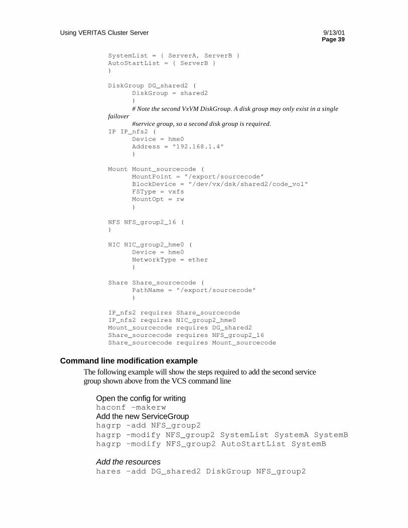
Using VERITAS Cluster Server 9/13/01 Page 39
SystemList = ServerA, ServerB AutoStartList = ServerB ) DiskGroup DG_shared2 ( DiskGroup = shared2 )
# Note the second VxVM DiskGroup. A disk group may only exist in a single failover
#service group, so a second disk group is required. IP IP_nfs2 ( Device = hme0 Address = "192.168.1.4" ) Mount Mount_sourcecode ( MountPoint = "/export/sourcecode" BlockDevice = "/dev/vx/dsk/shared2/code_vol" FSType = vxfs MountOpt = rw ) NFS NFS_group2_16 ( ) NIC NIC_group2_hme0 ( Device = hme0 NetworkType = ether ) Share Share_sourcecode ( PathName = "/export/sourcecode" ) IP_nfs2 requires Share_sourcecode IP_nfs2 requires NIC_group2_hme0
Mount_sourcecode requires DG_shared2 Share_sourcecode requires NFS_group2_16 Share_sourcecode requires Mount_sourcecode
Command line modification example The following example will show the steps required to add the second service group shown above from the VCS command line
Open the config for writing haconf –makerw Add the new ServiceGroup hagrp –add NFS_group2 hagrp -modify NFS_group2 SystemList SystemA SystemB hagrp -modify NFS_group2 AutoStartList SystemB Add the resources hares –add DG_shared2 DiskGroup NFS_group2
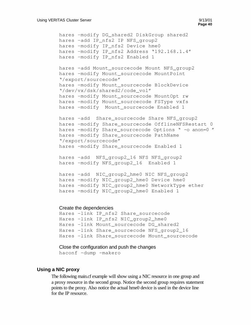
Using VERITAS Cluster Server 9/13/01 Page 40
hares –modify DG_shared2 DiskGroup shared2 hares –add IP_nfs2 IP NFS_group2 hares –modify IP_nfs2 Device hme0 hares –modify IP_nfs2 Address “192.168.1.4” hares –modify IP_nfs2 Enabled 1 hares –add Mount_sourcecode Mount NFS_group2 hares –modify Mount_sourcecode MountPoint “/export/sourcecode” hares –modify Mount_sourcecode BlockDevice “/dev/vx/dsk/shared2/code_vol” hares –modify Mount_sourcecode MountOpt rw hares –modify Mount_sourcecode FSType vxfs hares –modify Mount_sourcecode Enabled 1 hares –add Share_sourcecode Share NFS_group2 hares –modify Share_sourcecode OfflineNFSRestart 0 hares –modify Share_sourcecode Options “ -o anon=0 ” hares –modify Share_sourcecode PathName “/export/sourcecode” hares –modify Share_sourcecode Enabled 1
hares –add NFS_group2_16 NFS NFS_group2 hares –modify NFS_group2_16 Enabled 1 hares –add NIC_group2_hme0 NIC NFS_group2 hares –modify NIC_group2_hme0 Device hme0 hares –modify NIC_group2_hme0 NetworkType ether hares –modify NIC_group2_hme0 Enabled 1
Create the dependencies Hares –link IP_nfs2 Share_sourcecode Hares –link IP_nfs2 NIC_group2_hme0 Hares –link Mount_sourcecode DG_shared2 Hares –link Share_sourcecode NFS_group2_16 Hares –link Share_sourcecode Mount_sourcecode Close the configuration and push the changes haconf –dump –makero
Using a NIC proxy The following main.cf example will show using a NIC resource in one group and a proxy resource in the second group. Notice the second group requires statement points to the proxy. Also notice the actual hme0 device is used in the device line for the IP resource.
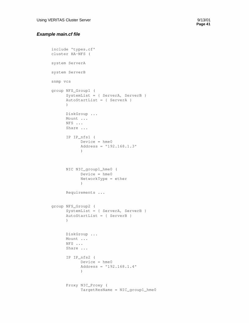
Using VERITAS Cluster Server 9/13/01 Page 41
Example main.cf file
include "types.cf" cluster HA-NFS ( system ServerA system ServerB snmp vcs group NFS_Group1 ( SystemList = ServerA, ServerB AutoStartList = ServerA ) DiskGroup ... Mount ... NFS ... Share ... IP IP_nfs1 ( Device = hme0 Address = "192.168.1.3" ) NIC NIC_group1_hme0 ( Device = hme0 NetworkType = ether ) Requirements ... group NFS_Group2 ( SystemList = ServerA, ServerB AutoStartList = ServerB ) DiskGroup ... Mount ... NFS ... Share ... IP IP_nfs2 ( Device = hme0 Address = "192.168.1.4" ) Proxy NIC_Proxy ( TargetResName = NIC_group1_hme0
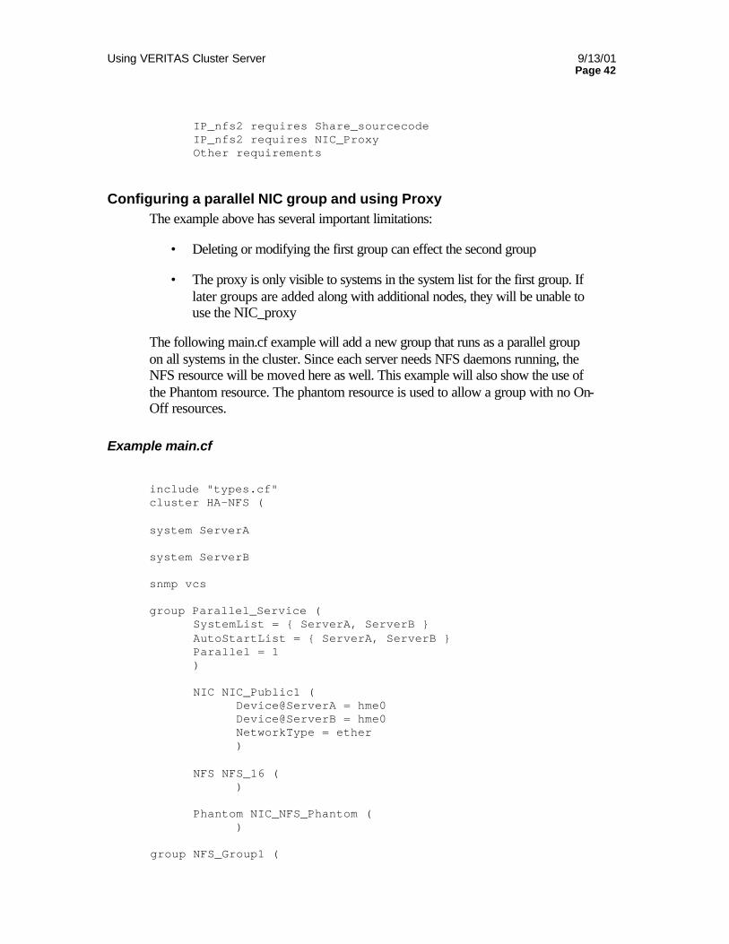
Using VERITAS Cluster Server 9/13/01 Page 42
IP_nfs2 requires Share_sourcecode IP_nfs2 requires NIC_Proxy Other requirements
Configuring a parallel NIC group and using Proxy The example above has several important limitations:
• Deleting or modifying the first group can effect the second group
• The proxy is only visible to systems in the system list for the first group. If later groups are added along with additional nodes, they will be unable to use the NIC_proxy
The following main.cf example will add a new group that runs as a parallel group on all systems in the cluster. Since each server needs NFS daemons running, the NFS resource will be moved here as well. This example will also show the use of the Phantom resource. The phantom resource is used to allow a group with no On-Off resources.
Example main.cf
include "types.cf" cluster HA-NFS ( system ServerA system ServerB snmp vcs group Parallel_Service ( SystemList = ServerA, ServerB AutoStartList = ServerA, ServerB Parallel = 1 )
NIC NIC_Public1 ( Device@ServerA = hme0 Device@ServerB = hme0 NetworkType = ether ) NFS NFS_16 (
) Phantom NIC_NFS_Phantom ( )
group NFS_Group1 (
Using VERITAS Cluster Server 9/13/01 Page 43
SystemList = ServerA, ServerB AutoStartList = ServerA ) DiskGroup ... Mount ... Share ... IP IP_nfs1 ( Device = hme0 Address = "192.168.1.3" ) Proxy NFS_Proxy_Group1 ( TargetResName = NFS_16 ) Proxy NIC_Proxy_Group1 ( TargetResName = NIC_Public1 ) Requirements ... IP_nfs1 requires NIC_Proxy_Group1 Share_home requires NFS_Proxy_Group1 Other requirements
group NFS_Group2 ( SystemList = ServerA, ServerB AutoStartList = ServerB ) DiskGroup ... Mount ... NFS ... Share ... IP IP_nfs2 ( Device = hme0 Address = "192.168.1.4" ) Proxy NFS_Proxy_Group2 ( TargetResName = NFS_16 ) Proxy NIC_Proxy_Group2 ( TargetResName = NIC_Public1 IP_nfs2 requires NIC_Proxy_Group2
Share_sourcecode requires NFS_Proxy_Group2
Using VERITAS Cluster Server 9/13/01 Page 44
Other requirements
Special storage considerations for NFS Service NFS servers and clients use the concept of a “filehandle”. This concept is based on an NFS design principal that the client is unaware of the underlying layout or architecture of an NFS server’s file system. When a client wishes to access a file, the server responds with a filehandle. This filehandle is used for all subsequent access to the file. For example, a client has the /export/home file system NFS mounted on /home and is currently in /home/user. The client system wishes to open the file /home/user/letter. The client NFS process issues an NFS lookup procedure call to the server for the file letter. The server responds with a filehandle that the client can use to access letter. This filehandle is considered an “opaque data type” to the client. The client has no visibility into what the filehandle contains, it simply knows to use this handle when it wishes to access letter. To the server, the filehandle has a very specific meaning. The filehandle encodes all information necessary to access a specific piece of data on the server. Typical NFS file handles contain the major and minor number of the file system, the inode number and the inode generation number (a sequential number assigned when an inode is allocated to a file. This is to prevent a client from mistakenly accessing a file by inode number that has been deleted and the inode reused to point to a new file). The NFS filehandle describes to the server one unique file on the entire server. If a client accesses the server using a filehandle that does not appear to work, such as major or minor number that are different than what is available on the server, or an inode number where the inode generation number is incorrect, the server will reply with a “Stale NFS filehandle” error. Many sites have seen this error after a full restore of a NFS exported file system. In this scenario, the files from a full file level restore are written in a new order with new inode and inode generation numbers for all files. In this scenario, all clients must unmount the file system and re-mount to receive new filehandle assignments from the server.
Rebooting an NFS server has no effect on an NFS client other than an outage while the server boots. Once the server is back, the client mounted file systems are accessible with the same file handles.
From a cluster perspective, a file system failover must look exactly like a very rapid server reboot. In order for this to occur, a filehandle valid on one server must point to the identical file on the peer server. Within a given file system located on shared storage this is guaranteed as inode and inode generation must match since they are read out of the same storage following a failover. The problem exists with major and minor numbers used by Unix to access the disks or volumes used for the storage. From a straight disk perspective, different controllers would use different minor numbers. If two servers in a cluster do not have exactly matching controller and slot layout, this can be a problem.
Using VERITAS Cluster Server 9/13/01 Page 45
This problem is greatly mitigated through the use of VERITAS Volume Manager. VxVM abstracts the data from the physical storage. In this case, the Unix major number is a pointer to VxVM and the minor number to a volume within a disk group. Problems arise in two situations. The first is differing major numbers. This typically occurs when the VxVM, VxFS and VCS are installed in different orders. Both VxVM and LLT/GAB use major numbers assigned by Solaris during software installation to create device entries. Installing in different orders will cause a mismatch in major number. Another cause of differing major numbers is different packages installed on each system prior to installing VxVM. Differing minor numbers within VxVM setup is rare and usually only happens when a server has a large number of local disk groups and volumes prior to beginning setup as a cluster peer.
Before beginning VCS NFS server configuration, verify file system major and minor numbers match between servers. On VxVM this will require importing the disk group on one server, checking major and minor, deporting the disk group then repeating the process on the second server.
If any problems arise, refer to the VCS Installation Guide, Preparing NFS Services.
Oracle sample configurations The following examples will show a two-node cluster running a single Oracle instance in an asymmetrical configuration and a 2 Oracle instance symmetrical configuration. It will also show the required changes to the Oracle configuration file such as listener.ora and tnsnames.ora.
Oracle setup As described above, the best method to configure a complex application like Oracle is to first configure one system to run Oracle properly and test. After successful test of the database on one server, import the shared storage and configure the second system identically. The most common configuration mistakes in VCS Oracle are system configuration files. On Unix these are typically /etc/system (/stand/system on HP), /etc/passwd, /etc/shadow and /etc/group.
Oracle must also be configured to operate in the cluster environment. The main Oracle setup task is to ensure all data required by the database resides on shared storage. During failover the second server must be able to access all table spaces, data files, control files, logs, etc. The Oracle listener must also be modified to work in the cluster. The changes typically required are $ORACLE_HOME/network/admin/tnsnames.ora and $ORACLE_HOME/network/admin/listener.ora. These files must be modified to use the hostname and IP address if the virtual server rather than a particular physical server. Remember to take this in to account during Oracle setup and
Using VERITAS Cluster Server 9/13/01 Page 46
testing. If you are using the physical address of a server, the listener control files must be changed during testing on the second server. If you use the high availability IP address selected for the Oracle service group, you will need to manually configure this address up on each machine during testing.
Many customers set up multiple Oracle users to simplify administration of multiple databases. For example, rather than logging in as “oracle” and specifying the prod SID, you can create an oraprod user with all required environment variables set to point to the proper Oracle home and SID
Always plan for expansion. Databases tend to proliferate. When you set up a single asymmetrical instance, plan ahead for the cluster to support multiple instances in the near future.
Oracle Enterprise Agent installation To control Oracle in a VCS environment, the customer must purchase and install the VCS Enterprise Agent for Oracle. This package actually contains two agents, the OracleAgent to control the Oracle database and the SqlnetAgent to control the Oracle listener. Follow the instructions in the Enterprise Agent for Oracle Installation and Configuration Guide for details.
Single instance configuration The following example will show a single instance asymmetric failover configuration for Oracle 8i. The configuration assumes the following system configurations
• Cluster HA-Oracle
• Servers: ServerA and ServerB
• Service group ORA_PROD_Group
• Storage: One disk group, DG_oraprod
• File Systems: /prod/u01 and /prod/u02
• IP address: 192.168.1.6 IP_oraprod
• Public interface: hme0
• ServerA is primary location to start the ORA_PROD_Group
• The Listener starts before the Oracle database to allow Multi Threaded Server usage.
• DNS mapping for 192.168.1.6 maps to host “oraprod”
Using VERITAS Cluster Server 9/13/01 Page 47
Example main.cf include "types.cf" include "OracleTypes.cf" cluster HA-Oracle ( ) system SystemA system SystemB snmp vcs group ORA_PROD_Group ( SystemList = ServerA, ServerB AutoStartList = ServerA ) DiskGroup DG_oraprod ( DiskGroup = ora_prod_dg StartVolumes = 0 StopVolumes = 0 ) IP IP_oraprod ( Device = hme0 Address = "192.168.1.6" ) Mount Mount_oraprod_u01 ( MountPoint = "/prod/u01" BlockDevice = "/dev/vx/dsk/ora_prod_dg/u01-vol" FSType = vxfs MountOpt = rw ) Mount Mount_oraprod_u02 ( MountPoint = "/prod/u02" BlockDevice = "/dev/vx/dsk/ora_prod_dg/u02-vol" FSType = vxfs MountOpt = rw ) NIC NIC_oraprod_hme0 ( Device = hme0 NetworkType = ether ) Oracle ORA_oraprod ( Critical = 1 Sid = PROD Owner = oraprod Home = "/prod/u01/oracle/product/8.1.5" Pfile = "/prod/u01/oracle/admin/pfile/initPROD.ora" ) Sqlnet LSNR_oraprod_lsnr (
Using VERITAS Cluster Server 9/13/01 Page 48
Owner = oraprod Home = "/prod/u01/oracle/product/8.1.5" TnsAdmin = "/prod/u01/oracle/network/admin" Listener = LISTENER_PROD ) Volume Vol_oraprod_vol1 ( Volume = "u01-vol" DiskGroup = "ora_prod_dg" ) Volume Vol_oraprod_vol2 ( Volume = "u01-vo2" DiskGroup = "ora_prod_dg" ) Vol_oraprod_vol1 requires DG_oraprod Vol_oraprod_vol2 requires DG_oraprod Mount_oraprod_u01 requires Vol_oraprod_vol1 Mount_oraprod_u02 requires Vol_oraprod_vol3 IP_oraprod requires NIC_oraprod_hme0 LSNR_oraprod_lsnr requires Mount_oraprod_u01 LSNR_oraprod_lsnr requires Mount_oraprod_u02 LSNR_oraprod_lsnr requires IP_oraprod ORA_oraprod requires LSNR_oraprod_lsnr
Oracle listener.ora configuration Listener.ora modifications for a single instance configuration are quite simple. Edit the “Host=” line in the ADDRESS_LIST section and add the name of the high availability address for the service group, in this case, “oraprod”.
LISTENER_PROD = (ADDRESS_LIST = (ADDRESS=(PROTOCOL= TCP)(Host=oraprod)(Port=1521)) ) SID_LIST_LISTENER_PROD= (SID_LIST = (SID_DESC= (GLOBAL_DBNAME=db01.) (ORACLE_HOME= /u01/oracle/product/8.1.5) (SID_NAME = PROD) ) (SID_DESC= (SID_NAME = extproc) (ORACLE_HOME= /u01/oracle/product/8.1.5) (PROGRAM= extproc) ) ) STARTUP_WAIT_TIME_LISTENER_PROD =0 CONNECT_TIMEOUT_LISTENER_PROD = 10 TRACE_LEVEL_LISTENER_PROD = OFF
Using VERITAS Cluster Server 9/13/01 Page 49
Adding deep level testing Deep level testing gives VCS the ability to test Oracle and the Listener from closer to a real user perspective. The OracleAgent will log into the database and write data to a table, logout, log back in and test that it can read from the same table. The SqlnetAgent will test that it can actually connect to the listener and access the database.
Oracle changes To configure deep level testing of the database, a low privilege user must be defined that can create and modify a table. The following is documented in the Sqltest.pl file in the $VCS_HOME/bin/Oracle directory.
The following test updates a row "tstamp" with the latest value of the Oracle internal function SYSDATE
A prerequisite for this test is that a user/password/table has been created before enabling the script by defining the VCS attributes User/Pword/Table/MonScript for the Oracle resource.
This task can be accomplished by the following SQL statements as DB-admin:
SVRMGR> connect internal SVRMGR> create user <User> 2> identified by <Pword> 3> default tablespace USERS 4> temporary tablespace USERS 5> quota 100K on USERS;
USERS is the tablespace name present at all standard Oracle Installations.
It might be replaced by any other tablespace for the specific installation.
(To get a list of valid tablespaces use: select * from sys.dba_tablespaces;)
SVRMGR> grant create session to <User>; SVRMGR> create table <User>.<Table> ( tstamp date ); SVRMGR> create table <User>.<Table> ( tstamp date ); SVRMGR> insert into <User>.<Table> ( tstamp ) values ( SYSDATE ); The name of the row "tstamp" should match the one of the update statement below!
To test DB-setup use:
SVRMGR> disconnect SVRMGR> connect <User>/<Pword> SVRMGR> update <User>.<Table> set ( tstamp ) = SYSDATE; SVRMGR> select TO_CHAR(tstamp, 'MON DD, YYYY HH:MI:SS AM')tstamp 2> from <User>.<Table>;
Using VERITAS Cluster Server 9/13/01 Page 50
SVRMGR> exit
If you received the correct timestamp the in depth testing can be enabled
VCS Configuration changes To enable VCS to perform deep level Oracle testing, you must define the Oracle user and password and the tablespace used for testing. The following is an example of the modifications to main.cf for the Oracle and Sqlnet resources:
Oracle ORA_oraprod ( Critical = 1 Sid = PROD Owner = oraprod Home = "/u01/oracle/product/8.1.5" Pfile = "/u01/oracle/admin/pfile/initPROD.ora" )
User = "testuser" Pword = "vcstest" Table = "USERS" Monscript = "/opt/VRTSvcs/bin/Oracle/SqlTest.pl"
Sqlnet PROD_Listener ( Owner = oraprod Home = "/u01/oracle/product/8.1.5" TnsAdmin = "/u01/oracle/network/admin" Listener = LISTENER_PROD
Monscript = "/opt/VRTSvcs/bin/Sqlnet/LsnrTest.pl" )
Multiple Instance configuration Multiple Oracle instances are really not difficult, however it does involve slightly more effort to setup. As with all applications, it is best to test the operation of the app before placing in VCS control. In this case, make sure you have modified all proper system files, such as /etc/system, /etc/passwd, /etc/group and /etc/shadow to support multiple databases. Pay particular attention to system requirements like physical memory and shared memory segment availability. Also ensure a single system is capable of sustaining a multiple instance load in the event of a server failure and extended operation on the backup server.
The following example will add a second instance for symmetrical failover. This configuration adds the following
• Service group ORA_MKTG_Group
• Storage: One disk group, DG_oramktg
• File Systems: /mktg/u01 and /mktg/u02
• IP address: 192.168.1.6 IP_oramktg
Using VERITAS Cluster Server 9/13/01 Page 51
• Public interface: hme0
• ServerB is primary location to start the ORA_MKTG_Group
• The Listener starts before the Oracle database to allow Multi Threaded Server usage.
• DNS mapping for 192.168.1.7 maps to host “oramktg”
• Parallel NIC group and NIC proxy
Example main.cf include "types.cf" include "OracleTypes.cf" cluster HA-Oracle ( ) system SystemA system SystemB snmp vcs group ORA_PROD_Group ( SystemList = ServerA, ServerB AutoStartList = ServerA ) DiskGroup DG_oraprod ( DiskGroup = ora_prod_dg StartVolumes = 0 StopVolumes = 0 ) IP IP_oraprod ( Device = hme0 Address = "192.168.1.6" ) Mount Mount_oraprod_u01 ( MountPoint = "/prod/u01" BlockDevice = "/dev/vx/dsk/ora_prod_dg/u01-vol" FSType = vxfs MountOpt = rw ) Mount Mount_oraprod_u02 ( MountPoint = "/prod/u02" BlockDevice = "/dev/vx/dsk/ora_prod_dg/u02-vol" FSType = vxfs MountOpt = rw ) Oracle ORA_oraprod (
Using VERITAS Cluster Server 9/13/01 Page 52
Critical = 1 Sid = PROD Owner = oraprod Home = "/prod/u01/oracle/product/8.1.5" Pfile = "/u01/oracle/admin/pfile/initPROD.ora" ) Proxy NIC_prod_proxy ( TargetResName = NIC_Public1 ) Sqlnet LSNR_oraprod_lsnr ( Owner = oraprod Home = "/prod/u01/oracle/product/8.1.5" TnsAdmin = "/prod/u01/oracle/network/admin" Listener = LISTENER_PROD ) Volume Vol_oraprod_vol1 ( Volume = "u01-vol" DiskGroup = "ora_prod_dg" ) Volume Vol_oraprod_vol2 ( Volume = "u01-vo2" DiskGroup = "ora_prod_dg" ) Vol_oraprod_vol1 requires DG_oraprod Vol_oraprod_vol2 requires DG_oraprod Mount_oraprod_u01 requires Vol_oraprod_vol1 Mount_oraprod_u02 requires Vol_oraprod_vol3 IP_oraprod requires NIC_prod_proxy LSNR_oraprod_lsnr requires Vol_oraprod_vol1 LSNR_oraprod_lsnr requires Vol_oraprod_vol2 LSNR_oraprod_lsnr requires IP_oraprod ORA_oraprod requires LSNR_oraprod_lsnr
group ORA_MKTG_Group ( SystemList = ServerA, ServerB AutoStartList = ServerB ) DiskGroup DG_oramktg ( DiskGroup = ora_mktg_dg StartVolumes = 0 StopVolumes = 0 ) IP IP_oramktg ( Device = hme0 Address = "192.168.1.7" )
Using VERITAS Cluster Server 9/13/01 Page 53
Proxy NIC_mktg_proxy ( TargetResName = NIC_Public1 ) Mount Mount_oramktg_u01 ( MountPoint = "/mktg/u01" BlockDevice = "/dev/vx/dsk/ora_mktg_dg/u01-vol" FSType = vxfs MountOpt = rw ) Mount Mount_oramktg_u02 ( MountPoint = "/mktg/u02" BlockDevice = "/dev/vx/dsk/ora_mktg_dg/u02-vol" FSType = vxfs MountOpt = rw ) Oracle ORA_oramktg ( Critical = 1 Sid = MKTG Owner = oramktg Home = "/mktg/u01/oracle/product/8.1.5" Pfile = "/mktg/u01/oracle/admin/pfile/initMKTG.ora" ) Sqlnet LSNR_oraprod_lsnr ( Owner = oramktg Home = "/mktg/u01/oracle/product/8.1.5" TnsAdmin = "/mktg/u01/oracle/network/admin" Listener = LISTENER_MKTG ) Volume Vol_oramktg_vol1 ( Volume = "u01-vol" DiskGroup = "ora_mktg_dg" ) Volume Vol_oramktg_vol2 ( Volume = "u01-vo2" DiskGroup = "ora_mktg_dg" ) Vol_oramktg_vol1 requires DG_oramktg Vol_oramktg_vol2 requires DG_oramktg Mount_oramktg_u01 requires Vol_oramktg_vol1 Mount_oramktg_u02 requires Vol_oramktg_vol2 IP_oramktg requires NIC_mktg_proxy LSNR_oramktg_lsnr requires Mount_oramktg_u01 LSNR_oramktg_lsnr requires Mount_oramktg_u02 LSNR_oramktg_lsnr requires IP_oramktg ORA_oramktg requires LSNR_oramktg_lsnr
group Parallel_Service (
Using VERITAS Cluster Server 9/13/01 Page 54
SystemList = ServerA, ServerB AutoStartList = ServerA, ServerB Parallel = 1 )
NIC NIC_Public1 ( Device@ServerA = hme0 Device@ServerB = hme0 NetworkType = ether )
Phantom NIC_Phantom ( )
)
Oracle listener.ora configuration In order to support multiple instances running on different locations, the Oracle Listener configuration must be modified. Supporting multiple independent (capable of running on any server in any combination) requires individual listeners per database. This requires changes to listener.ora and tnsnames.ora.
The listener.ora configuration will now list two independent listener configurations.
LISTENER_PROD = (ADDRESS_LIST = (ADDRESS=(PROTOCOL= TCP)(Host=oraprod)(Port=1521)) ) SID_LIST_LISTENER_PROD= (SID_LIST = (SID_DESC= (GLOBAL_DBNAME=db01.) (ORACLE_HOME= /prod/u01/oracle/product/8.1.5) (SID_NAME = PROD) ) (SID_DESC= (SID_NAME = extproc) (ORACLE_HOME= /prod/u01/oracle/product/8.1.5) (PROGRAM= extproc) ) ) STARTUP_WAIT_TIME_LISTENER_PROD =0 CONNECT_TIMEOUT_LISTENER_PROD = 10 TRACE_LEVEL_LISTENER_PROD = OFF
LISTENER_MKTG = (ADDRESS_LIST = (ADDRESS=(PROTOCOL= TCP)(Host=oramktg)(Port=1521)) )
Using VERITAS Cluster Server 9/13/01 Page 55
SID_LIST_LISTENER_MKTG= (SID_LIST = (SID_DESC= (GLOBAL_DBNAME=db01.) (ORACLE_HOME= /mktg/u01/oracle/product/8.1.5) (SID_NAME = MKTG) ) (SID_DESC= (SID_NAME = extproc) (ORACLE_HOME= /mktg/u01/oracle/product/8.1.5) (PROGRAM= extproc) ) ) STARTUP_WAIT_TIME_LISTENER_MKTG =0 CONNECT_TIMEOUT_LISTENER_MKTG = 10 TRACE_LEVEL_LISTENER_MKTG = OFF
Location of Oracle Binaries Where to install Oracle binaries in a cluster configuration is an ongoing question that has no “correct” answer. Placing Oracle binaries on shared storage has its advantages as does placing the binaries on local system disk. The following section will attempt to detail the pros and cons of each.
Oracle binaries on shared disk Placing Oracle binaries on shared disk simplifies setting up a given system in a multinode cluster to run an instance. In this way, each database service group is completely self-contained. The shared storage contains the oracle binaries, all control and parameter files and all table spaces. This means an instance can be moved to a new server in the cluster at will, as soon as it is a part of the cluster, has its required system file changes made and assumes it can see the storage. In a multinode configuration running multiple versions of Oracle, this is many times the best way to go. Imagine a 4-node cluster, supporting 3 database instances/Service Groups, each at a different version. Placing the binaries on shared storage would require maintaining 3 copies of oracle (one per Service Group). Placing the binaries on local disk would require maintaining 12 copies (4 servers X 3 versions)
The downside to this approach means each instance must be maintained separately and rolling upgrades are not possible. Since the binaries are contained in the Service Group, it is not possible to update the Oracle version on one system then bring the database online, then upgrade the other systems.
Oracle binaries on local disk Placing binaries on local disk has its own advantages and disadvantages as well. One key benefit to local disk is the ability to do a rolling patch or version upgrade of Oracle. Imagine a two-node cluster running Oracle 8.1.5. The customer wishes to go to Oracle 8.1.6. With the database running on one system, the customer may be able to upgrade/install the new version on the offline system. The database can
Using VERITAS Cluster Server 9/13/01 Page 56
then be switched over with absolute minimum downtime to the new version. The second server can then be upgraded. This method may not work in all cases, depending on changes to the database structure, but may provide some rolling upgrade capability.
The issue with this method is scalability. As the number of instances, versions and servers grows, the number of copies of software to maintain grows out of proportion to the benefits.
What is the correct choice? The correct location for Oracle binaries is whatever fits the needs of the environment. The customer will need to weigh all pros and cons of each method and make the correct choice for their needs.
Using IPMultiNIC and MultiNICA The MultiNICA resource is a special configuration to allow “in box failover” of a faulted network connection. Upon detecting a failure of a configured network interface, VCS will move the IP address to a second standby interface in the same system. This can be far less costly in terms of service outage than a complete service group failover to a peer in many cases. It must be noted that there is still an interruption of service between the time a network card or cable fails, detection of the failure and migration to a new interface. The MultiNICA resource also keeps a base address up on an interface, essentially providing a highly available maintenance address.
The IPMultiNIC resource is a special IP resource designed to sit on top of a MultiNICA resource. Just as IP sits on an NIC resource, IPMultiNIC can only sit on a MultiNICA resource. IPMultiNIC configures and moves the HA IP address between hosts
Configuring IPMultiNIC and MultiNICA resource pairs In a normal VCS configuration, the IP resource is dependent on the NIC resource. To use a high availability NIC configuration, VCS is configured to use the IPMultiNIC resource depending on the MultiNICA resource. The MultiNICA resource is responsible for maintaining the base IP address up on one of the assigned interfaces, and moving this IP on the event of a failure to another interface. The IPMultiNIC resource actually configures up the floating VCS IP address on the physical interface maintained by MultiNICA.
In the following example, two machines, ServerA and ServerB, each have a pair of network interfaces, qfe1 and qfe5. The two interfaces have the same base, or physical, IP address. This base address is moved between interfaces during a failure. Only one interface is ever active at a time. The addresses assigned to the interface pairs differ for each host. Since each host will have a physical address up and assigned to an interface during normal operation (base address, not HA
Using VERITAS Cluster Server 9/13/01 Page 57
address) the addresses must be different. Note the lines beginning at Device@ServerA; the use of different physical addresses shows how to localize an attribute for a particular host.
In the event of a NIC failure on sysa, the physical IP address and the logical IP addresses will fail over from qfe1 to qfe5. In the event that qfe5 fails, the address will fail back to qfe1 if qfe1 has been reconnected. However, if both the NICs on sysa are disconnected, the MultiNICA and IPMultiNIC resources work in tandem to fault the group on sysa. The entire group now fails over to sysb.
Example main.cf include "types.cf" include "OracleTypes.cf" cluster HA-Oracle ( ) system SystemA system SystemB snmp vcs group ORA_PROD_Group ( SystemList = ServerA, ServerB AutoStartList = ServerA ) DiskGroup ... Mount ... Mount ... Oracle ... Sqlnet ... Volume ... Volume ... IPMultiNIC IP_oraprod ( Address = "192.168.1.6" NetMask = "255.255.255.0" MultiNICResName = oramnic Options = "trailers" )
MultiNICA oramnic ( Device@SystemA = qfe0 = "192.168.1.1", qfe5 = "192.168.1.1" Device@SystemB = qfe0 = "192.168.1.2", qfe5 = "192.168.1.2"
NetMask = "255.255.255.0" Options = "trailers" )
Using VERITAS Cluster Server 9/13/01 Page 58
IP_oraprod requires oramnic
Notes about Using MultiNICA Agent If all the NICs configured in the Device attribute are down, the MultiNICA agent will fault the resource after a 2-3 minute interval. This delay occurs because the MultiNICA agent tests the failed NIC several times before marking the resource offline. Messages recorded in the engine log during failover provide a detailed description of the events that take place during failover. (The engine log is located at /var/VRTSvcs/log/engine_A.log).
The MultiNICA agent supports only one active NIC on one IP subnet; the agent will not work with multiple active NICs.
The primary NIC must be configured before VCS is started. You can use the ifconfig(1M) command to configure it manually, or edit the file /etc/hostname.nic (on Solaris) so that configuration of the NIC occurs automatically when the system boots. VCS plumbs and configures the backup NIC, so it does not require the file /etc/hostname.nic.
Using a Parallel MultiNICA group and Proxy The following example will show the use of MultiNICA, IPMultiNIC and Proxy together. In this example, the customer wants to use IPMultiNIC in each service group. They also want each service group to look identical from a configuration standpoint. This example will configure a parallel group on each server consisting of the MultiNICA resource and a Phantom resource and multiple Failover groups with a Proxy to the MultiNICA. Note the IPMultiNIC resource attribute MultiNICResName = mnic always points to the physical MultiNICA resource and not the proxy.
The parallel service group containing MultiNICA resources ensures there is a local instance of the MultiNICA resource running on the box.
Example main.cf include "types.cf" include "OracleTypes.cf" cluster HA-Oracle ( ) system SystemA system SystemB snmp vcs group ORA_PROD_Group ( SystemList = ServerA, ServerB AutoStartList = ServerA )
Using VERITAS Cluster Server 9/13/01 Page 59
IPMultiNIC IP_oraprod ( Device = MNIC_Public1 Address = "192.168.1.6" )
Proxy MNIC_prod_proxy ( TargetResName = MNIC_Public1 )
DiskGroup ...
Mount Mount_oraprod_u01 ...( Mount Mount_oraprod_u02 ... Oracle ORA_oraprod ... Sqlnet LSNR_oraprod_lsnr ... Volume Vol_oraprod_vol1 ... Volume Vol_oraprod_vol2 ... IP_oraprod requires MNIC_prod_proxy Other requirements
group ORA_MKTG_Group ( SystemList = ServerA, ServerB AutoStartList = ServerB ) IPMultiNIC IP_oramktg ( Device = MNIC_Public1 Address = "192.168.1.7" ) Proxy MNIC_mktg_proxy ( TargetResName = MNIC_Public1 )
DiskGroup ... Mount Mount_oramktg_u01 ...( Mount Mount_oramktg_u02 ... Oracle ORA_oramktg ... Sqlnet LSNR_oramktg_lsnr ... Volume Vol_oramktg_vol1 ... Volume Vol_oramktg_vol2 ... IP_oramktg requires MNIC_mktg_proxy Other requirements group Parallel_Service ( SystemList = ServerA, ServerB AutoStartList = ServerA, ServerB Parallel = 1 ) MultiNICA MNIC_Public1 (
Device@SystemA = qfe0 = "192.168.1.1", qfe5 = "192.168.1.1" Device@SystemB = qfe0 = "192.168.1.2", qfe5 = "192.168.1.2"
NetMask = "255.255.255.0"
Using VERITAS Cluster Server 9/13/01 Page 60
Options = "trailers" )
Phantom NIC_Phantom ( ) )
Altering Agent/Resource Type Behavior Altering behavior of agents is done at the resource type level. For example, modifying how often a resource is monitored while online or offline is set on a per resource type basis.
A large number of attributes are available that are understood by all agents (type independent) and allow tuning the behavior of resource types. This section will list the most common:
Common resource type attributes
ConfInterval ConfInterval determines how long a resource must remain online to be considered “healthy”. When a resource has remained online for the specified time (in seconds), previous faults and restart attempts are ignored by the agent. (See ToleranceLimit and RestartLimit attributes for details.) For example, an ApacheAgent is configured with the default ConfInterval of 300 seconds, or 5 minutes and a RestartLimit of 1. In this example, assume the Apache Web Server process is started and remains online for two hours before failing. With the RestartLimit set to 1, the ApacheAgent will restart the failing web server. If the server fails again before the time set by ConfInterval, the ApacheAgent inform HAD that the web server has failed and HAD will mark the resource as faulted and begin a failover for the Service Group. If instead, the web server stays online longer than the time specified by ConfInterval, the RestartLimit counter will be cleared. In this way, the resource could fail again at a later time and be restarted. The ConfInterval attribute gives the developer a method the discriminate between a resource that occasionally fails and one that is essentially bouncing up and down.
FaultOnMonitorTimeouts When a monitor fails as many times as the value specified, the corresponding resource is brought down by calling the clean entry point. The resource is then marked FAULTED, or it is restarted, depending on the value set in the RestartLimit attribute. When FaultOnMonitorTimeouts is set to 0, monitor failures are not considered indicative of a resource fault. (This attribute is available in versions of VCS above 1.2 only)
Default = 4
Using VERITAS Cluster Server 9/13/01 Page 61
MonitorInterval Duration (in seconds) between two consecutive monitor calls for an ONLINE or transitioning resource. The interval between monitor cycles directly affects the amount of time it takes to detect a failed resource. Reducing MonitorInterval can reduce time required for detection. At the same time, reducing this time also increases system load due to increased monitoring and can also increase the chance of false failure detection.
Default = 60 seconds
MonitorTimeout Maximum time (in seconds) within which the monitor entry point must complete or else be terminated. In VCS 1.3, a Monitor Timeout can be configured as a resource failure. On VCS 1.1.2, this simply caused a warning message in the VCS engine log.
Default = 60 seconds
OfflineMonitorInterval Duration (in seconds) between two consecutive monitor calls for an OFFLINE
resource. If set to 0, OFFLINE resources are not monitored. Individual resources are monitored on all systems in the SystemList of the service group the resource belongs to, even when they are OFFLINE. This is done to detect Concurrency Violations when a resource is started outside VCS control on another system. The default OfflineMonitorInterval is set to 5 minutes to reduce system loading imposed by monitoring offline service groups
Default = 300 seconds
OfflineTimeout Maximum time (in seconds) within which the offline entry point must complete or else be terminated. There are certain cases where the offline function may take a long time to complete, such as shutting down an active Oracle database. When writing custom agents, the developer must remember that is the function of the monitor entry point to actually check that the offline is successful, not the offline. In many cases, the offline timeout is due to attempting to wait for offline and do some sort of testing in the offline script.
Default = 300 seconds
OnlineRetryLimit Number of times to retry online, if the attempt to online a resource is unsuccessful. This parameter is meaningful only if clean is implemented. This attribute is different than RestartLimit in that it only applies during the initial attempt to bring a resource online when the service group is brought online. The
Using VERITAS Cluster Server 9/13/01 Page 62
counter for this value is reset when the monitor process reports the resource has been successfully brought online.
Default = 0
OnlineTimeout Maximum time (in seconds) within which the online entry point must complete or else be terminated. As with the offline timeout, the developer must remember that the function of the online entry point is to start the resource, not check if it is actually online. If extra time is needed to wait for the resource to come online, this should be coded in the online exit code in number of seconds to wait before monitoring.
Default = 300 seconds
RestartLimit Affects how the agent responds to a resource fault. If set to a value greater than zero, the agent will attempt to restart the resource when it faults. In order to utilize RestartLimit, a clean function must be implemented. The act of restarting a resource happens completely within the agent and is not reported to HAD. In this manner, a resource will still show as online on the VCS GUI or output of hastatus during this process. The resource will only be declared as offline if the restart is unsuccessful.
Default = 0
ToleranceLimit A non-zero ToleranceLimit allows the monitor entry point to return OFFLINE
several times before the resource is declared FAULTED. This is useful when a resource may be heavily loaded and end-to-end monitoring is in effect. For example, a web server under extreme load may not be able to respond to an in-depth monitor probe that connects and expects an html response. Setting a ToleranceLimit of greater than zero allows multiple monitor cycles to attempt the check before declaring a failure.
Default = 0
Usage example In the following example, a customer wishes to modify the way an Apache web server is handled by the ApacheAgent. The customer does not want the web server to be failed over unless it fails 4 times in a 10 minute period. Further, the web server is expected to sometimes respond slowly, so the customer wishes to retry a failed monitor at least once.
The following changes would be required in the ApacheTypes.cf file:

Using VERITAS Cluster Server 9/13/01 Page 63
type Apache ( int RestartLimit = 4 int ConfInterval = 600 int ToleranceLimit = 1 str ServerRoot str PidFile str IPAddr int Port str TestFile static str ArgList[] = ServerRoot, PidFile, IPAddr, Port, TestFile )
Configuring different agent behavior for multiple resources Setting attributes for resource types effects all resources of that type. In the above example, changing RestartLimit changes the restart behavior for all Apache resources. Modifications to agent behavior cannot be made at the individual resource level. If different values are required for different resources, it is simple to create a new resource type and agent.
For example, a customer wishes to monitor a group of web servers every 30 seconds for critical services and every 5 minutes for other web sites. The customer would create a second Apache type by copying the entire /opt/VRTSvcs/bin/Apache directory to something like /opt/VRTSvcs/bin/Apache1. The ApacheAgent in the new directory is renamed Apache1Agent. The user then copies the original ApacheTypes.cf entry to Apache1Types.cf such as the following.
type Apache ( int RestartLimit = 4 int ConfInterval = 600 int ToleranceLimit = 1 int MonitorInterval = 30 str ServerRoot str PidFile str IPAddr int Port str TestFile static str ArgList[] = ServerRoot, PidFile, IPAddr, Port, TestFile ) type Apache1 ( int RestartLimit = 4 int ConfInterval = 600 int ToleranceLimit = 1 int MonitorInterval = 300 str ServerRoot str PidFile str IPAddr int Port str TestFile static str ArgList[] = ServerRoot, PidFile, IPAddr, Port, TestFile )
Using VERITAS Cluster Server 9/13/01 Page 64
Service Group Workload Management (SGWM) As customers move into larger and larger servers, the need for “Server Consolidation” becomes evident. A large number of applications are being deployed on a more limited number of “Enterprise Class” servers. This is a perfect place for true N-to-N clustering. N-to-N refers to multiple Service Groups running on multiple servers, with each Service Group capable of being failed over to different servers in the cluster. For example, imagine a 4-node cluster, with each node supporting 3 critical database instances. On failure of any node, each of the three instances is started on a different node, ensuring on node does not get overloaded. This is a logical evolution of N + 1, where there is not a need for a “standby system” but rather “standby capacity” in the cluster. Cascading failure is also possible in this configuration. This refers to the cluster being able to tolerate multiple failures and best distribute Service Group load.
VCS 2.0 Service Group Workload Management (SGWM) is an advanced capability in VCS to proactively determine the best possible system to host an application during startup or following an application or server fault. SGWM provides necessary tools to make intelligent decisions on startup or failover location based on system capacity and finite resource availability.
SGWM Concepts Service Group Load Management is enabled when AutoStartPolicy and/or FailOverPolicy is set to “Load” As described in the Service Group Operations chapter, VCS has three primary settings for FailOverPolicy. These are Priority, RoundRobin and Load. Priority is the most basic. The system with the lowest priority in a running state is chosen. Priority is set implicitly via ordering in SystemList, such as SystemList = server1, server2 or by explicitly setting priority in the SystemList, such as SystemList = system1=0, system2=1. This is ideal for a simple two-node cluster, or a small cluster with a very small number of Service Groups. Priority is the default behavior in VCS. RoundRobin chooses the system running the least number of Service Groups as a failover target. This is ideal for larger clusters running a large number of Service Groups of essentially the same server load characteristics (for example similar databases or applications). Load is the most flexile and powerful policy. It provides the framework for true server consolidation at the data center. Load policy is made of two components, System Capacity and Service Group Load, and System Limits and Group Prerequisites.
Using VERITAS Cluster Server 9/13/01 Page 65
System Capacity and Service Group Load System Capacity sets a fixed load handling capacity to servers and a fixed demand (Load) for service groups. For example, imagine a 4-node cluster consisting of two 16-processor servers and two 8-processor servers. The administrator sets a Capacity on the 16-CPU to 200 and the 8-CPU to 100. Each Service Group running on a system has a predefined Load value. When a group comes online, its Load is subtracted from the Capacity of the system. The cluster engine keeps track of the AvailableCapacity of all systems in the cluster. AvailableCapacity is determined by subtracting Load of all groups online (a group is considered online if online or partially online) on a system from the system Capacity. When a failover must occur, the cluster engine determines the system with the highest AvailableCapacity and starts the group on that system. During a failover scenario involving multiple groups, failover decisions are made serially to facilitate the proper load based choice, however ServiceGroup online operations immediately follow in parallel. System Capacity is a soft restriction. This means that the value can go below zero. During a cascading failure scenario, AvailableCapacity can be negative.
Static Load vs. Dynamic Load Previous versions of VCS, prior to VCS 2.0, allowed the user to set the DynamicLoad of a server with an outside monitoring program. The user can run any monitoring package desired, and then feed estimated load to the VCS engine with the “hasys –load command”. In previous versions, the system with the lowest value in the DynamicLoad variable was chosen for a failover target if FailOverPolicy was set to Load. DynamicLoad is still available in VCS 2.0, but it now integrates with the SGWM framework. Typically, the engine sets remaining capacity with the function AvailableCapacity = Capacity – (Sum of Load of all online Service Groups) If DynamicLoad is specified with the hasys –load command, this value overrides calculated Load values. Using DynamicLoad, AvailableCapacity = Capacity – DynamicLoad. This allows a user to more finely control system-loading values than estimated Service Group loading. The downside is the user must setup and maintain a load estimation package outside VCS. One caveat to note: DynamicLoad specified with hasys –load would be subtracted from Capacity as an integer, and not a percentage. For example, if a system has a Capacity of 200, and the outside package determines the server is 80% loaded, the package should inform VCS that DynamicLoad is 160 (rather than 80). This is done by first querying VCS for the value of Capacity with the hasys –display command, then using this value to calculate the actual load value to pass back in. Future releases of VCS will allow specifying the DynamicLoad value as a percentage. To clarify: AvailableCapacity of a system = Capacity – Current System Load
Using VERITAS Cluster Server 9/13/01 Page 66
Current System Load = Dynamic system load if dynamic system load is specified, (DynamicLoad > 0) OR
Current System Load = Sum of Load of all groups online on that system
Limits and Prerequisites System Limits and Service Group Prerequisites add additional capability to the load policy. The user can set a list of finite resources available on a server (Limits), such as shared memory segments, semaphores and others. Each Service group is then assigned a set of Prerequisites. For example, a database may need 3 shared memory segments and 10 semaphores. VCS load policy will first determine a subset of all systems that meet these criteria and then choose the lowest loaded system from this set. In this way, an unloaded system that does not meet all the Prerequisites of a group will not be chosen. As soon as the decision is made to online a group on a particular system, the Prerequisites of the group is subtracted from the Limits of the system. When configuring Limits and Prerequisites, users should first define group Prerequisites and then define corresponding Limits on each system. Each system can have different limit. There is no limit on number of group prerequisites or system limits. Also, they can appear in any order. Not all the groups have to define all Prerequisites and not all systems have to define all Limits. If system does not have defined limits for a given system resource, then default value of 0 is assumed. Similarly, when group does not define Prerequisites for given system resource, a default value of 0 is assumed. All of the prerequisites specified in a group’s Prerequisites must be met. System Limits and group Prerequisites can be used creatively in many ways. For example, if someone wants only one group online on a system at a time, following configuration will work:
Prerequisites = GroupWeight = 1 Limits = GroupWeight = 1
Adding the above entries to the definition of each group and system will make sure that each system can have only one group online at a time. System Limits and Group Prerequisites work independently of FailOverPolicy. Prerequisites are used to determine a sub set of eligible systems that a group can be started on during failover or startup. Once a list of systems meeting proper Prerequisites is created, the engine will then follow the configured FailOverPolicy.
Capacity and Limits Together Capacity and limits combined make a very powerful tool for determining proper failover node. The system with all proper prerequisites and with the highest available capacity is
Using VERITAS Cluster Server 9/13/01 Page 67
always chosen. If multiple systems meet the required Prerequisites, and have the same AvailableCapacity, the system lexically first in the SystemList is chosen System Limits are a hard value. This means a server will not be chosen if it does not meet the Prerequisites of the group. This cannot be overridden. Capacity is a soft limit. This means the system with the highest AvailableCapacity will be chosen, even if this will result in a negative AvailableCapacity. Systems with an AvailableCapacity of less than the percentage set by LoadWarningLevel, and staying at that load for longer than LoadTimeThreshold seconds will invoke the Overload trigger described below.
Overload Warning Overload warning provides the notification piece of the load policy. When a server sustains a pre-determined load level set by LoadWarningLevel (static or dynamically determined) for a predetermined time, set by LoadTimeThreshold, the loadwarning trigger is initiated. (See Triggers for a full description of Event Management with Triggers). The loadwarning trigger is a user defined script or application designed to carry out the proper actions. Sample scripts detail simple operator warning on overload as well as a method to move or shutdown groups based on user defined priority values. For example, if load on a server running a business critical database reaches and stays above a user defined threshold, operators will be immediately notified. The loadwarning trigger could then scan the system for any service groups with a lower priority than the database (such as an internal HR app) and move the app to a lesser-loaded system or even shut the app down. The key here is the framework is completely flexible. The installer or user is free to implement any overload management scheme desired.
SystemZones SystemZones provide a sub set of systems to use in an initial failover decision. A ServiceGroup will try to stay within its zone before choosing a host in another zone. For example, imagine a typical 3-tier application infrastructure with web servers, application servers and database servers. The application and database servers are configured in a single cluster. Using SystemZones would require a ServiceGroup in the application zone to try to fail to another application zone server if it is available. If not, it would then fail to the database zone based on load and limits. In this configuration, excess capacity and limits available on the database backend would essentially be kept in reserve for the larger load of a database failover, while application servers would handle the load of any groups in the application zone. During a cascading failure, excess capacity in the cluster is still available to any ServiceGroup. The SystemZones feature allows fine tuning application failover decisions, yet still retains the flexibility to fail anywhere in the cluster if necessary.
Load Based AutoStart VCS 2.0 provides a new method to determine where a group should come up when the cluster initially starts. Administrators can set the AutoStartPolicy to Load and allow the
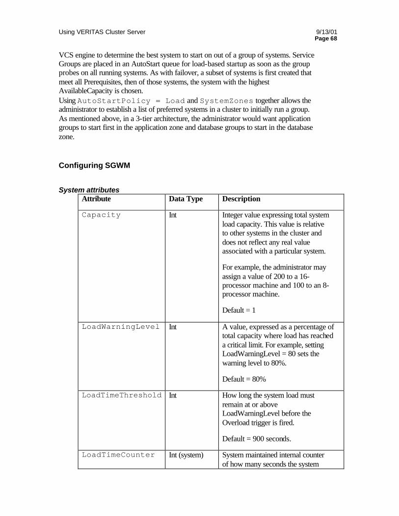
Using VERITAS Cluster Server 9/13/01 Page 68
VCS engine to determine the best system to start on out of a group of systems. Service Groups are placed in an AutoStart queue for load-based startup as soon as the group probes on all running systems. As with failover, a subset of systems is first created that meet all Prerequisites, then of those systems, the system with the highest AvailableCapacity is chosen. Using AutoStartPolicy = Load and SystemZones together allows the administrator to establish a list of preferred systems in a cluster to initially run a group. As mentioned above, in a 3-tier architecture, the administrator would want application groups to start first in the application zone and database groups to start in the database zone. Configuring SGWM
System attributes Attribute Data Type Description
Capacity Int Integer value expressing total system load capacity. This value is relative to other systems in the cluster and does not reflect any real value associated with a particular system.
For example, the administrator may assign a value of 200 to a 16-processor machine and 100 to an 8-processor machine.
Default = 1
LoadWarningLevel Int A value, expressed as a percentage of total capacity where load has reached a critical limit. For example, setting LoadWarningLevel = 80 sets the warning level to 80%.
Default = 80%
LoadTimeThreshold Int How long the system load must remain at or above LoadWarningLevel before the Overload trigger is fired.
Default = 900 seconds.
LoadTimeCounter Int (system) System maintained internal counter of how many seconds the system
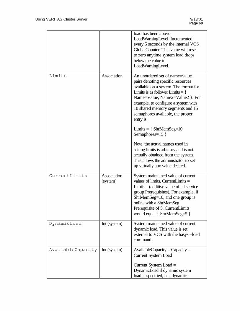
Using VERITAS Cluster Server 9/13/01 Page 69
load has been above LoadWarningLevel. Incremented every 5 seconds by the internal VCS GlobalCounter. This value will reset to zero anytime system load drops below the value in LoadWarningLevel.
Limits Association An unordered set of name=value pairs denoting specific resources available on a system. The format for Limits is as follows: Limits = Name=Value, Name2=Value2 . For example, to configure a system with 10 shared memory segments and 15 semaphores available, the proper entry is:
Limits = ShrMemSeg=10, Semaphores=15
Note, the actual names used in setting limits is arbitrary and is not actually obtained from the system. This allows the administrator to set up virtually any value desired.
CurrentLimits Association (system)
System maintained value of current values of limits. CurrentLimits = Limits – (additive value of all service group Prerequisites). For example, if ShrMemSeg=10, and one group is online with a ShrMemSeg Prerequisite of 5, CurrentLimits would equal ShrMemSeg=5
DynamicLoad Int (system) System maintained value of current dynamic load. This value is set external to VCS with the hasys –load command.
AvailableCapacity Int (system) AvailableCapacity = Capacity – Current System Load
Current System Load = DynamicLoad if dynamic system load is specified, i.e., dynamic
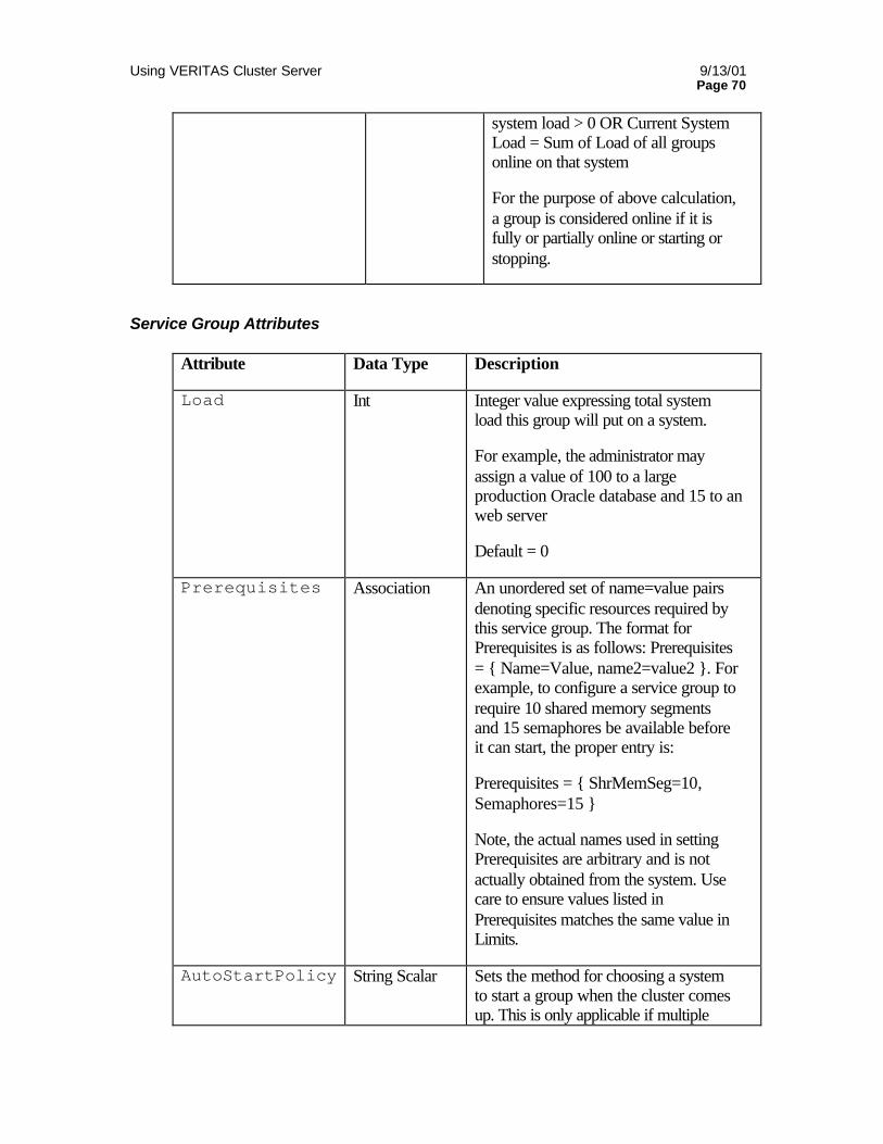
Using VERITAS Cluster Server 9/13/01 Page 70
system load > 0 OR Current System Load = Sum of Load of all groups online on that system
For the purpose of above calculation, a group is considered online if it is fully or partially online or starting or stopping.
Service Group Attributes
Attribute Data Type Description
Load Int Integer value expressing total system load this group will put on a system.
For example, the administrator may assign a value of 100 to a large production Oracle database and 15 to an web server
Default = 0
Prerequisites Association An unordered set of name=value pairs denoting specific resources required by this service group. The format for Prerequisites is as follows: Prerequisites = Name=Value, name2=value2 . For example, to configure a service group to require 10 shared memory segments and 15 semaphores be available before it can start, the proper entry is:
Prerequisites = ShrMemSeg=10, Semaphores=15
Note, the actual names used in setting Prerequisites are arbitrary and is not actually obtained from the system. Use care to ensure values listed in Prerequisites matches the same value in Limits.
AutoStartPolicy String Scalar Sets the method for choosing a system to start a group when the cluster comes up. This is only applicable if multiple
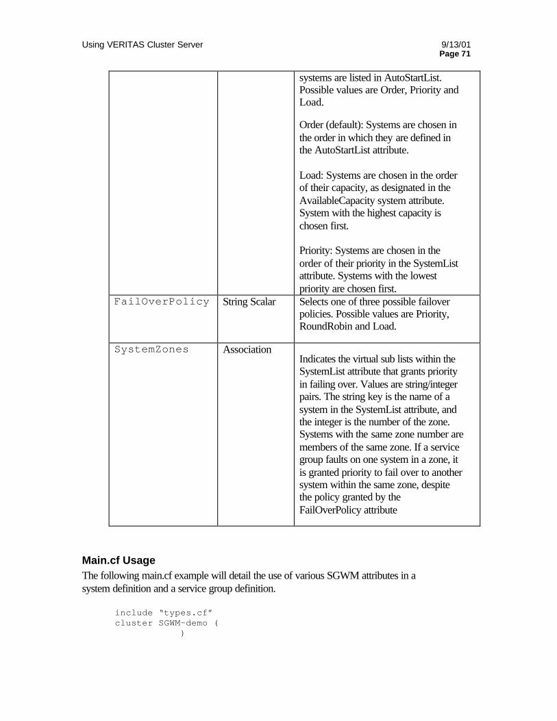
Using VERITAS Cluster Server 9/13/01 Page 71
systems are listed in AutoStartList. Possible values are Order, Priority and Load.
Order (default): Systems are chosen in the order in which they are defined in the AutoStartList attribute. Load: Systems are chosen in the order of their capacity, as designated in the AvailableCapacity system attribute. System with the highest capacity is chosen first. Priority: Systems are chosen in the order of their priority in the SystemList attribute. Systems with the lowest priority are chosen first.
FailOverPolicy String Scalar Selects one of three possible failover policies. Possible values are Priority, RoundRobin and Load.
SystemZones Association Indicates the virtual sub lists within the SystemList attribute that grants priority in failing over. Values are string/integer pairs. The string key is the name of a system in the SystemList attribute, and the integer is the number of the zone. Systems with the same zone number are members of the same zone. If a service group faults on one system in a zone, it is granted priority to fail over to another system within the same zone, despite the policy granted by the FailOverPolicy attribute
Main.cf Usage The following main.cf example will detail the use of various SGWM attributes in a system definition and a service group definition.
include “types.cf” cluster SGWM-demo (
)

Using VERITAS Cluster Server 9/13/01 Page 72
system LargeSvr1 ( Capacity = 200 Limits = ShrMemSeg=20, Semaphores=10, Processors=12 LoadWarningLevel = 90 LoadTimeThreshold = 600 ) group G1 ( SystemList = LgSvr1, LgSvr2, MedSvr1, MedSvr2 SystemZones = LgSvr1=0, LgSvr2=0, MedSvr1=1, MedSvr2=1 AutoStartPolicy = Load AutoStartList = MedSvr1, MedSvr2 FailOverPolicy = Load Load = 100
Prerequisites = ShrMemSeg=10, Semaphores=5, Processors=6 )
SGWM Examples
Simple 4-node limits only example The following example details a simple use of Limits and Prerequisites to control the total number of Service Groups that may run on any one node. The cluster consists of 4 similar servers. There are 5 service groups, which are roughly equal in overall processing power requirement and amount of load they put on a system. All servers can host 2 such groups. Note that this does not use group Load and system Capacity. Also, the groups use default AutoStartPolicy and FailOverPolicy. Main.cf sample
system Svr1 ( Limits = GroupWeight = 2
) system Svr2 (
Limits = GroupWeight = 2 ) system Svr3 (
Limits = GroupWeight = 2 ) system Svr4 (
Limits = GroupWeight = 2 ) group G1 (
SystemList = Svr1, Svr2, Svr3, Srv4 AutoStartList = Svr1, Svr2 Prerequisites = GroupWeight = 1
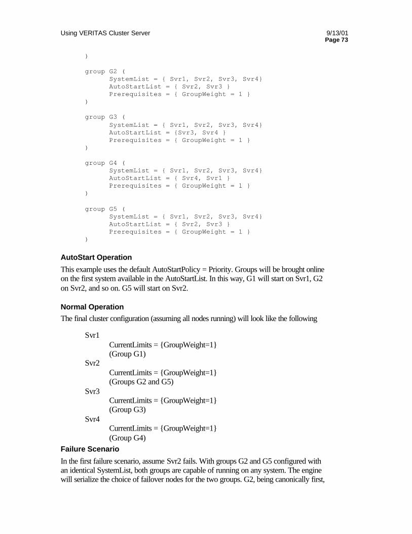
Using VERITAS Cluster Server 9/13/01 Page 73
) group G2 (
SystemList = Svr1, Svr2, Svr3, Svr4 AutoStartList = Svr2, Svr3 Prerequisites = GroupWeight = 1
) group G3 (
SystemList = Svr1, Svr2, Svr3, Svr4 AutoStartList = Svr3, Svr4 Prerequisites = GroupWeight = 1
) group G4 (
SystemList = Svr1, Svr2, Svr3, Svr4 AutoStartList = Svr4, Svr1 Prerequisites = GroupWeight = 1
) group G5 (
SystemList = Svr1, Svr2, Svr3, Svr4 AutoStartList = Svr2, Svr3 Prerequisites = GroupWeight = 1
)
AutoStart Operation
This example uses the default AutoStartPolicy = Priority. Groups will be brought online on the first system available in the AutoStartList. In this way, G1 will start on Svr1, G2 on Svr2, and so on. G5 will start on Svr2.
Normal Operation
The final cluster configuration (assuming all nodes running) will look like the following
Svr1 CurrentLimits = GroupWeight=1
(Group G1) Svr2
CurrentLimits = GroupWeight=1 (Groups G2 and G5) Svr3
CurrentLimits = GroupWeight=1 (Group G3) Svr4
CurrentLimits = GroupWeight=1 (Group G4)
Failure Scenario
In the first failure scenario, assume Svr2 fails. With groups G2 and G5 configured with an identical SystemList, both groups are capable of running on any system. The engine will serialize the choice of failover nodes for the two groups. G2, being canonically first,
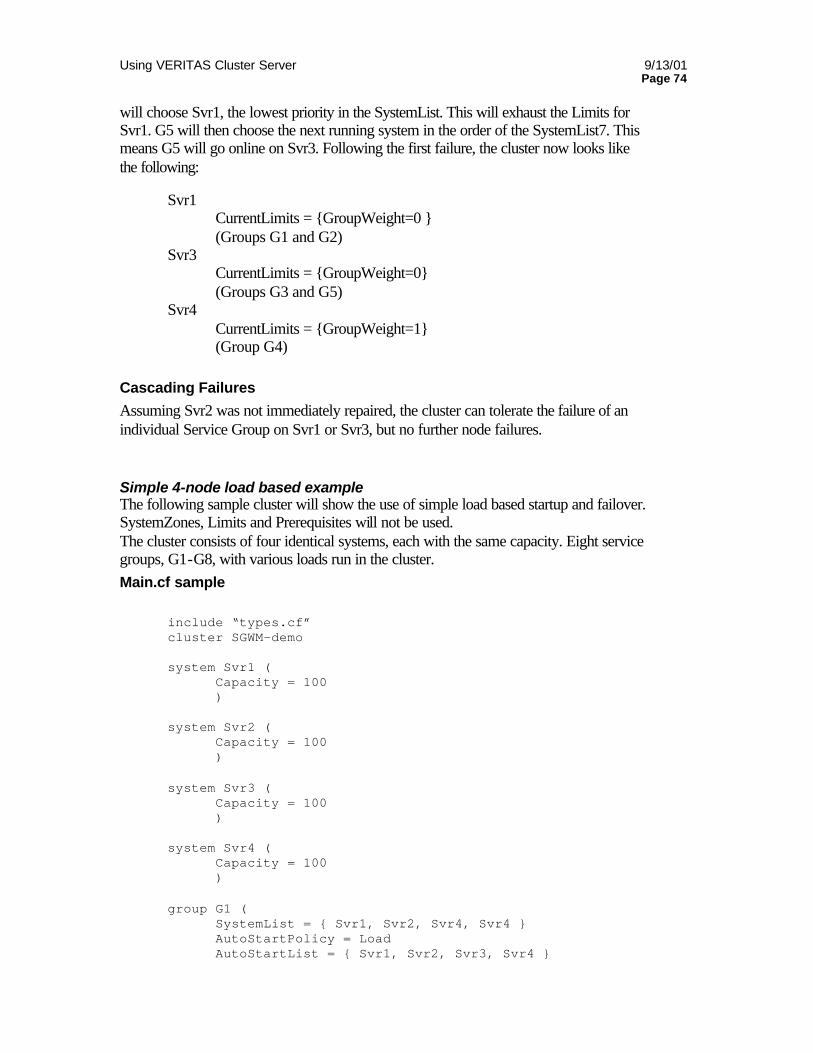
Using VERITAS Cluster Server 9/13/01 Page 74
will choose Svr1, the lowest priority in the SystemList. This will exhaust the Limits for Svr1. G5 will then choose the next running system in the order of the SystemList7. This means G5 will go online on Svr3. Following the first failure, the cluster now looks like the following:
Svr1 CurrentLimits = GroupWeight=0 (Groups G1 and G2) Svr3
CurrentLimits = GroupWeight=0 (Groups G3 and G5) Svr4 CurrentLimits = GroupWeight=1 (Group G4)
Cascading Failures
Assuming Svr2 was not immediately repaired, the cluster can tolerate the failure of an individual Service Group on Svr1 or Svr3, but no further node failures.
Simple 4-node load based example The following sample cluster will show the use of simple load based startup and failover. SystemZones, Limits and Prerequisites will not be used. The cluster consists of four identical systems, each with the same capacity. Eight service groups, G1-G8, with various loads run in the cluster. Main.cf sample
include “types.cf” cluster SGWM-demo system Svr1 ( Capacity = 100 ) system Svr2 ( Capacity = 100 ) system Svr3 ( Capacity = 100 ) system Svr4 ( Capacity = 100 ) group G1 ( SystemList = Svr1, Svr2, Svr4, Svr4 AutoStartPolicy = Load AutoStartList = Svr1, Svr2, Svr3, Svr4
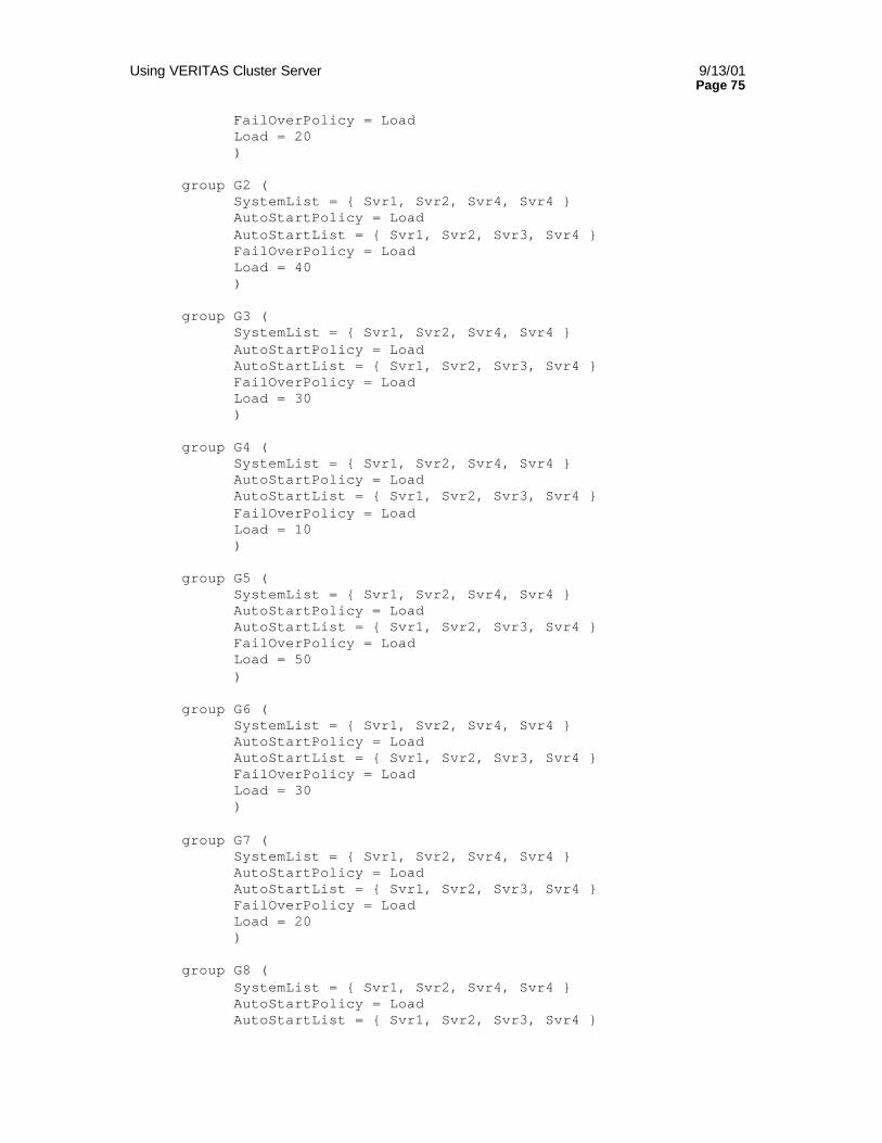
Using VERITAS Cluster Server 9/13/01 Page 75
FailOverPolicy = Load Load = 20 ) group G2 ( SystemList = Svr1, Svr2, Svr4, Svr4 AutoStartPolicy = Load AutoStartList = Svr1, Svr2, Svr3, Svr4 FailOverPolicy = Load
Load = 40 )
group G3 ( SystemList = Svr1, Svr2, Svr4, Svr4 AutoStartPolicy = Load AutoStartList = Svr1, Svr2, Svr3, Svr4 FailOverPolicy = Load
Load = 30 )
group G4 ( SystemList = Svr1, Svr2, Svr4, Svr4 AutoStartPolicy = Load AutoStartList = Svr1, Svr2, Svr3, Svr4 FailOverPolicy = Load
Load = 10 )
group G5 ( SystemList = Svr1, Svr2, Svr4, Svr4 AutoStartPolicy = Load AutoStartList = Svr1, Svr2, Svr3, Svr4 FailOverPolicy = Load
Load = 50 )
group G6 ( SystemList = Svr1, Svr2, Svr4, Svr4 AutoStartPolicy = Load AutoStartList = Svr1, Svr2, Svr3, Svr4 FailOverPolicy = Load
Load = 30 )
group G7 ( SystemList = Svr1, Svr2, Svr4, Svr4 AutoStartPolicy = Load AutoStartList = Svr1, Svr2, Svr3, Svr4 FailOverPolicy = Load
Load = 20 )
group G8 ( SystemList = Svr1, Svr2, Svr4, Svr4 AutoStartPolicy = Load AutoStartList = Svr1, Svr2, Svr3, Svr4
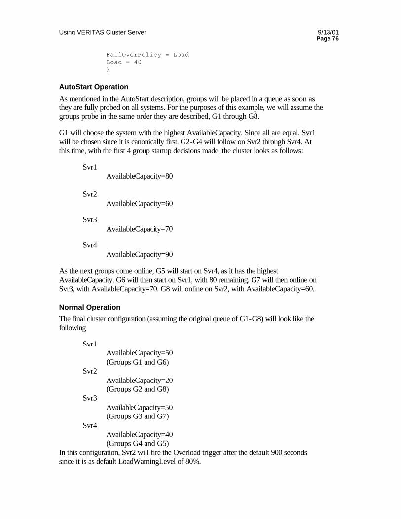
Using VERITAS Cluster Server 9/13/01 Page 76
FailOverPolicy = Load Load = 40 )
AutoStart Operation
As mentioned in the AutoStart description, groups will be placed in a queue as soon as they are fully probed on all systems. For the purposes of this example, we will assume the groups probe in the same order they are described, G1 through G8.
G1 will choose the system with the highest AvailableCapacity. Since all are equal, Svr1 will be chosen since it is canonically first. G2-G4 will follow on Svr2 through Svr4. At this time, with the first 4 group startup decisions made, the cluster looks as follows:
Svr1 AvailableCapacity=80 Svr2 AvailableCapacity=60 Svr3 AvailableCapacity=70 Svr4 AvailableCapacity=90
As the next groups come online, G5 will start on Svr4, as it has the highest AvailableCapacity. G6 will then start on Svr1, with 80 remaining. G7 will then online on Svr3, with AvailableCapacity=70. G8 will online on Svr2, with AvailableCapacity=60.
Normal Operation
The final cluster configuration (assuming the original queue of G1-G8) will look like the following
Svr1 AvailableCapacity=50 (Groups G1 and G6) Svr2 AvailableCapacity=20 (Groups G2 and G8) Svr3 AvailableCapacity=50 (Groups G3 and G7) Svr4 AvailableCapacity=40 (Groups G4 and G5)
In this configuration, Svr2 will fire the Overload trigger after the default 900 seconds since it is as default LoadWarningLevel of 80%.
Using VERITAS Cluster Server 9/13/01 Page 77
Failure Scenario
In the first failure scenario, assume Svr4 fails. This will immediately queue G4 and G5 for failure decision. G4 will choose Svr1, as it and Svr3 have AvailableCapacity=50 and Svr1 is canonically first. G5 will go online on Svr3. Once again, remember that failure decisions are made serially, not actual online and offline operations. The serializing of the failover choice allows complete load based control, and adds less than one second to total failover time.
Following the first failure, the cluster now looks like the following:
Svr1 AvailableCapacity=40 (Groups G1, G6 and G4) Svr2 AvailableCapacity=20 (Groups G2 and G8) Svr3 AvailableCapacity=0 (Groups G3, G7 and G5)
In this configuration, Svr3 will now fire the loadwarning trigger to notify administrators that the server is overloaded. The operator could switch G7 to Svr1 to balance loading across G1 and G3. As soon as Svr4 is repaired, it will rejoin the cluster with an AvailableCapacity=100. Any further failover would be sent to Svr4.
Cascading Failures
Assuming Svr4 was not immediately repaired, further failures would be possible. For this example, assume Svr3 now fails. G3 will immediately choose Svr1, G5 will choose Svr2, and finally G7 will choose Svr1. This will result in the following:
Svr1 AvailableCapacity= -10 (Groups G1, G6, G4, G3 and G7) Svr2 AvailableCapacity= -30 (Groups G2 and G8 and G5)
In this example, we can see how Capacity is a soft limit, and can go below zero.
Complex 4-node example The following example will detail the use of various SGWM attributes 4-node cluster using multiple system capacities and various limits. The cluster consists of 2 large Enterprise servers (LgSvr1 and LgSvr2) and two Medium servers (MedSvr1 and MedSvr2). There are also 4 Service Groups, G1 through G4, with various loads and
Using VERITAS Cluster Server 9/13/01 Page 78
prerequisites. G1 and G2 are database applications, with specific shared memory and semaphore requirements, G3 and G4 are middle tier applications with no specific memory or semaphores requirements, and simply add load to a given system. Main.cf sample
include “types.cf” cluster SGWM-demo (
) system LgSvr1 ( Capacity = 200 Limits = ShrMemSeg=20, Semaphores=10, Processors=12 LoadWarningLevel = 90 LoadTimeThreshold = 600 ) system LgSvr2 ( Capacity = 200 Limits = ShrMemSeg=20, Semaphores=10, Processors=12 LoadWarningLevel=70 LoadTimeThreshold=300 ) system MedSvr1 ( Capacity = 100 Limits = ShrMemSeg=10, Semaphores=5, Processors=6 ) system MedSvr2 ( Capacity = 100 Limits = ShrMemSeg=10, Semaphores=5, Processors=6 ) group G1 ( SystemList = LgSvr1, LgSvr2, MedSvr1, MedSvr2 SystemZones = LgSvr1=0, LgSvr2=0, MedSvr1=1, MedSvr2=1 AutoStartPolicy = Load AutoStartList = LgSvr1, LgSvr2 FailOverPolicy = Load Load = 100
Prerequisites = ShrMemSeg=10, Semaphores=5, Processors=6 ) group G2 ( SystemList = LgSvr1, LgSvr2, MedSvr1, MedSvr2 SystemZones = LgSvr1=0, LgSvr2=0, MedSvr1=1, MedSvr2=1 AutoStartPolicy = Load AutoStartList = LgSvr1, LgSvr2 FailOverPolicy = Load Load = 100
Prerequisites = ShrMemSeg=10, Semaphores=5, Processors=6
Using VERITAS Cluster Server 9/13/01 Page 79
)
group G3 ( SystemList = LgSvr1, LgSvr2, MedSvr1, MedSvr2 SystemZones = LgSvr1=0, LgSvr2=0, MedSvr1=1, MedSvr2=1 AutoStartPolicy = Load AutoStartList = MedSvr1, MedSvr2 FailOverPolicy = Load Load = 30 ) group G4 ( SystemList = LgSvr1, LgSvr2, MedSvr1, MedSvr2 SystemZones = LgSvr1=0, LgSvr2=0, MedSvr1=1, MedSvr2=1 AutoStartPolicy = Load AutoStartList = MedSvr1, MedSvr2 FailOverPolicy = Load Load = 20 )
AutoStart Operation
Using the main.cf example above, it can be seen that the following is the likely outcome of the AutoStart operation G1 – LgSvr1 G2 – LgSvr2 G3 – MedSvr1 G4 – MedSvr2 All groups will begin a probe sequence when the cluster starts. Groups G1 and G2 have an AutoStartList of LgSvr1 and LgSvr2. When these groups probe, the will be queued to go online on one of these servers, based on highest AvailableCapacity. Assuming G1 probes first, it will choose LgSvr1 because LgSvr1 and LgSvr2 both have an initial AvailableCapacity of 200, and LgSvr1 is lexically first. The same sequence will occur with G3 and G4 determining which server to chose between MedSvr1 and MedSvr2. Normal Operation
Assuming the running configuration described, the following can be determined: LgSvr1 AvailableCapacity=100 CurrentLimits = ShrMemSeg=10, Semaphores=6, Processors=6 LgSvr2
Using VERITAS Cluster Server 9/13/01 Page 80
AvailableCapacity=100 CurrentLimits = ShrMemSeg=10, Semaphores=5, Processors=6 MedSvr1 AvailableCapacity=70 CurrentLimits = ShrMemSeg=10, Semaphores=5, Processors=6 MedSvr2 AvailableCapacity=80 CurrentLimits = ShrMemSeg=10, Semaphores=5, Processors=6
Failure Scenario
For the first failure example, assume system LgSvr2 fails. The cluster engine will first scan all available systems in G2’s SystemList, with the same SystemZones grouping as the server it was running on. It will then create a subset of systems meeting the group’s Prerequisites. In this case, LgSvr1 meets all necessary Limits. G2 will be brought online on LgSvr1. This will result in the following configuration: LgSvr1 AvailableCapacity=0 CurrentLimits = ShrMemSeg=0, Semaphores=0, Processors=0 MedSvr1 AvailableCapacity=70 CurrentLimits = ShrMemSeg=10, Semaphores=5, Processors=6 MedSvr2 AvailableCapacity=80 CurrentLimits = ShrMemSeg=10, Semaphores=5, Processors=6 After 10 minutes, (LoadTimeThreshold = 600) the loadwarning trigger on LgSvr1 will fire, as LoadWarningLevel is exceeding 90%. Cascading Failure Scenario
In this scenario, a further failure of any system can be tolerated, as each system has remaining Limits sufficient to accommodate the group running on the peer. If a failure were to occur with either MedSvr1 or MedSvr2, the opposite MedSvr would be chosen, as groups running there have MedSvr1 and MedSvr2 in their SystemZones. . If a failure instead occurred with LgSvr1, running two groups (with LgSvr2 still offline), the failover of the two groups will be serialized for the decision process. In this case, no systems exist in the database zone. The first group canonically, G1, will chose MedSvr2, as it meets all Limits and has the highest AvailableCapacity. Group G2 will automatically choose MedSvr1, as it would be the only remaining system that meets necessary Limits.
Using VERITAS Cluster Server 9/13/01 Page 81
Server Consolidation Example The following example will detail a complex 8-node cluster running multiple applications and several large databases. The database servers are all large enterprise systems, LgSvr1, LgSvr2 and LgSvr3. The middle tier servers running multiple applications are MedSvr1, MedSvr2, MedSvr3, MedSvr4 and MedSvr5. Main.cf sample
include “types.cf” cluster SGWM-demo (
) system LgSvr1 ( Capacity = 200 Limits = ShrMemSeg=15, Semaphores=30, Processors=18 LoadWarningLevel = 80 LoadTimeThreshold = 900 ) system LgSvr2 ( Capacity = 200 Limits = ShrMemSeg=15, Semaphores=30, Processors=18 LoadWarningLevel=80 LoadTimeThreshold=900 ) system LgSvr3 ( Capacity = 200 Limits = ShrMemSeg=15, Semaphores=30, Processors=18 LoadWarningLevel=80 LoadTimeThreshold=900 ) system MedSvr1 ( Capacity = 100 Limits = ShrMemSeg=5, Semaphores=10, Processors=6 ) system MedSvr2 ( Capacity = 100 Limits = ShrMemSeg=5, Semaphores=10, Processors=6 ) system MedSvr3 ( Capacity = 100 Limits = ShrMemSeg=5, Semaphores=10, Processors=6 ) system MedSvr4 ( Capacity = 100 Limits = ShrMemSeg=5, Semaphores=10, Processors=6 ) system MedSvr5 (

Using VERITAS Cluster Server 9/13/01 Page 82
Capacity = 100 Limits = ShrMemSeg=5, Semaphores=10, Processors=6 ) group Database1 ( SystemList = LgSvr1, LgSvr2, LgSvr3, MedSvr1, MedSvr2, MedSvr3, MedSvr4, MedSvr5 SystemZones = LgSvr1=0, LgSvr2=0, LgSvr3=0, MedSvr1=1, MedSvr2=1, MedSvr3=1, MedSvr4=1, MedSvr5=1 AutoStartPolicy = Load AutoStartList = LgSvr1, LgSvr2, LgSvr3 FailOverPolicy = Load Load = 100
Prerequisites = ShrMemSeg=5, Semaphores=10, Processors=6 ) group Database2 ( SystemList = LgSvr1, LgSvr2, LgSvr3, MedSvr1, MedSvr2, MedSvr3, MedSvr4, MedSvr5 SystemZones = LgSvr1=0, LgSvr2=0, LgSvr3=0, MedSvr1=1, MedSvr2=1, MedSvr3=1, MedSvr4=1, MedSvr5=1 AutoStartPolicy = Load AutoStartList = LgSvr1, LgSvr2, LgSvr3 FailOverPolicy = Load Load = 100
Prerequisites = ShrMemSeg=5, Semaphores=10, Processors=6 ) group Database3 ( SystemList = LgSvr1, LgSvr2, LgSvr3, MedSvr1, MedSvr2, MedSvr3, MedSvr4, MedSvr5 SystemZones = LgSvr1=0, LgSvr2=0, LgSvr3=0, MedSvr1=1, MedSvr2=1, MedSvr3=1, MedSvr4=1, MedSvr5=1 AutoStartPolicy = Load AutoStartList = LgSvr1, LgSvr2, LgSvr3 FailOverPolicy = Load Load = 100
Prerequisites = ShrMemSeg=5, Semaphores=10, Processors=6 ) group Application1 ( SystemList = LgSvr1, LgSvr2, LgSvr3, MedSvr1, MedSvr2, MedSvr3, MedSvr4, MedSvr5 SystemZones = LgSvr1=0, LgSvr2=0, LgSvr3=0, MedSvr1=1, MedSvr2=1, MedSvr3=1, MedSvr4=1, MedSvr5=1 AutoStartPolicy = Load AutoStartList = MedSvr1, MedSvr2, MedSvr3, MedSvr4, MedSvr5 FailOverPolicy = Load
Using VERITAS Cluster Server 9/13/01 Page 83
Load = 50 ) group Application2 ( SystemList = LgSvr1, LgSvr2, LgSvr3, MedSvr1, MedSvr2, MedSvr3, MedSvr4, MedSvr5 SystemZones = LgSvr1=0, LgSvr2=0, LgSvr3=0, MedSvr1=1, MedSvr2=1, MedSvr3=1, MedSvr4=1, MedSvr5=1 AutoStartPolicy = Load AutoStartList = MedSvr1, MedSvr2, MedSvr3, MedSvr4, MedSvr5 FailOverPolicy = Load Load = 50 ) group Application3 ( SystemList = LgSvr1, LgSvr2, LgSvr3, MedSvr1, MedSvr2, MedSvr3, MedSvr4, MedSvr5 SystemZones = LgSvr1=0, LgSvr2=0, LgSvr3=0, MedSvr1=1, MedSvr2=1, MedSvr3=1, MedSvr4=1, MedSvr5=1 AutoStartPolicy = Load AutoStartList = MedSvr1, MedSvr2, MedSvr3, MedSvr4, MedSvr5 FailOverPolicy = Load Load = 50 ) group Application4 ( SystemList = LgSvr1, LgSvr2, LgSvr3, MedSvr1, MedSvr2, MedSvr3, MedSvr4, MedSvr5 SystemZones = LgSvr1=0, LgSvr2=0, LgSvr3=0, MedSvr1=1, MedSvr2=1, MedSvr3=1, MedSvr4=1, MedSvr5=1 AutoStartPolicy = Load AutoStartList = MedSvr1, MedSvr2, MedSvr3, MedSvr4, MedSvr5 FailOverPolicy = Load Load = 50 )
group Application5 ( SystemList = LgSvr1, LgSvr2, LgSvr3, MedSvr1, MedSvr2, MedSvr3, MedSvr4, MedSvr5 SystemZones = LgSvr1=0, LgSvr2=0, LgSvr3=0, MedSvr1=1, MedSvr2=1, MedSvr3=1, MedSvr4=1, MedSvr5=1 AutoStartPolicy = Load AutoStartList = MedSvr1, MedSvr2, MedSvr3, MedSvr4, MedSvr5 FailOverPolicy = Load Load = 50 )
AutoStart Operation
Using VERITAS Cluster Server 9/13/01 Page 84
Using the main.cf example above, we can assume the following AutoStart Sequence:
Database1 – LgSvr1 Database2 – LgSvr2 Database3 – LgSvr3 Application1 – MedSvr1 Application2 – MedSvr2 Application3 – MedSvr3 Application4 – MedSvr4 Application5 – MedSvr5
Normal Operation
Assuming the running configuration described, the following can be determined: LgSvr1 AvailableCapacity=100 CurrentLimits = ShrMemSeg=10, Semaphores=20, Processors=12 LgSvr2 AvailableCapacity=100 CurrentLimits = ShrMemSeg=10, Semaphores=20, Processors=12 LgSvr3 AvailableCapacity=100 CurrentLimits = ShrMemSeg=10, Semaphores=20, Processors=12 MedSvr1 AvailableCapacity=50 CurrentLimits = ShrMemSeg=5, Semaphores=10, Processors=6 MedSvr2 AvailableCapacity=50 CurrentLimits = ShrMemSeg=5, Semaphores=10, Processors=6 MedSvr3 AvailableCapacity=50 CurrentLimits = ShrMemSeg=5, Semaphores=10, Processors=6 MedSvr4 AvailableCapacity=50 CurrentLimits = ShrMemSeg=5, Semaphores=10, Processors=6 MedSvr5 AvailableCapacity=50 CurrentLimits = ShrMemSeg=5, Semaphores=10, Processors=6
Using VERITAS Cluster Server 9/13/01 Page 85
Failure Scenario
The configuration above is an ideal example of FailOverPolicy=Load and SystemZones. The database zone (System Zone 0) is capable of handling up to two failures. Each server has adequate Limits to support up to three Database Service groups (with an expected performance drop with all groups running on one server). Similarly, the Application zone has excess capacity built into each machine. One other fact to note: The Application group machines all specify Limits to support one database, even though the Application groups do not run any Prerequisites. This will allow a database to fail across SystemZones if absolutely necessary and run on the least loaded application zone machine. For the first failure example, assume system LgSvr3 fails. The cluster engine will first scan all available systems in Database2’s SystemList, with the same SystemZones grouping as the server it was running on. It will then create a subset of systems meeting the group’s Prerequisites. In this case, LgSvr1 and LgSvr2 meet all necessary Limits. Database1 will be brought online on LgSvr1. This will result in the following configuration: LgSvr1 AvailableCapacity=0 CurrentLimits = ShrMemSeg=5, Semaphores=10, Processors=6 LgSvr2 AvailableCapacity=100 CurrentLimits = ShrMemSeg=10, Semaphores=15, Processors=12 In this scenario, a further failure of any system can be tolerated, as each system has remaining Limits sufficient to accommodate the group running on the peer. Cascading Failure Scenario
If the performance of a specific database is unacceptable with two database groups running on one server (or three following a second failure), the SystemZones policy has another helpful effect. Failing a database group into the Application zone has the effect of resetting its preferred zone. For example, in the above scenario, Database1 has been moved to LgSvr1. The administrator could reconfigure the application zone to move two application groups to one system. Then the database application can be switched to the empty application server (MedSvr1-MedSvr5). This will place Database1 in Zone1 (Application zone). If a failure occurs in Database1, it will pick the least loaded server in the Application zone meeting its Prerequisites.
Using VERITAS Cluster Server 9/13/01 Page 86
Common Problems
AutoDisabled Service groups A Service Group is AutoDisabled by VCS whenever there is any chance the group may be online elsewhere and VCS would be unable to detect this case. Service Groups online are not affected by this state, but they are prevented from staring anywhere else. Service groups are autodisabled in the following circumstances
• A system running a group faults while it was in Jeopardy. In this case, we realize the group was online on this system and se do not know if the system is really dead or suffered a network fault.
• HAD is halted on a system, but LLT and GAB remain running. This can be cause by killing HAD and HASHADOW simultaneously, or using hastop or hastop –force.
• LLT has lost connection to a system, but disk heartbeat is still present. In this case, we know the node is alive, but have no visibility to resource status.
• All resources are not probed on all running systems. This can occur during cluster startup or node addition. Resources not probing can be caused by a number of factors, including resource misconfiguration in main.cf or proper agents not installed on all systems.
Clearing an AutoDisabled flag can be done from the GUI or the command line with the hagrp –autoenable groupname command. This command should not be run until the administrator determines the cause of the AutoDisabled condition! The system has entered this state to prevent possible data corruption. The administrator MUST verify no resource from the affected group is online on any system in the cluster before clearing the flag.
Resources Not Probed Resources in a VCS cluster are monitored to determine if they are offline or online at regular intervals. Before a Service Group can be brought online (failover groups) HAD must determine that all resources in the group are offline on all systems configured to run the group. It does this by running a monitor cycle on all resources in question. Common problems preventing resource probing include:
• Agent required to monitor a resource is not installed. This most often happens when adding Enterprise or Custom Agents.
• Resource not configured correctly. Placing incorrect resource definitions in the main.cf file can make it impossible to test if the resource is offline
• Agents not running on a system. This is often seen if the system runs out of virtual memory or allowable number of processes
Using VERITAS Cluster Server 9/13/01 Page 87
Stale/Invalid Configuration Stale configuration at startup is probably the most common VCS issue. This can only be caused by an invalid configuration or a .stale file. See the Configuration File replication section for more information.
Application/Resources not starting Applications or resources not starting in VCS can be frustrating to troubleshoot. As soon as the application fails, VCS wants to failover all resources to another system. The first piece of problem resolution is to determine when the error occurred. If this is a brand new install and the app has not yet run under VCS control, has it been tested outside VCS control? It is recommended applications always be tested outside VCS prior to bringing under cluster control. This is key for complex applications like Oracle. Most problems are system and application setup related and not VCS.
Once you have hand tested the application, verify the resource is properly configured in the main.cf file. Then attempt to bring online under VCS control. Monitor the engine.log_A via tail, or with the log monitor on the GUI. This will provide the first warning of anything wrong.
Another technique that may help is to use the GUI or command line to start all resources the app depends on, and then freeze the service group. This will prevent VCS from taking action if the application faults. You may then hand start the application and see if the problem exists with the application, or perhaps with the resource configuration below the application in the Service Group.
Failover Times and Other Performance Issues A very common question posed by prospective clustering customers is “How long does it take to fail over my application, such as Oracle?” This is a difficult question, as the answer is invariably “It depends”. Failover time for an application is almost entirely dependant on the application and not VCS. The second common question is “What is the performance impact of VCS on my server?”
The following section is taken almost directly from the VCS Users Guide, titled VCS Performance Considerations (Thank you to Darshan Joshi.) It will cover times required to fail over and switch over Service Groups and overall impact on a server by VCS.
VCS Failure Detection/Failover Performance This section describes factors that affect VCS operations, such as bringing a resource or service group online, taking them offline, and failing over service groups over to a different system.
Using VERITAS Cluster Server 9/13/01 Page 88
Bringing a Service Group Online The time it takes to bring a service group online depends on the number of resources in the service group, the service group topology, and the time to online the group’s resources. For example, if a service group G1 has three resources, R1, R2, and R3 (where R1 depends on R2 and R2 depends on R3), VCS first onlines R3. When R3 is online, VCS onlines R2. When R2 is online, VCS onlines R1. The time it takes to online G1 equals the time it takes to bring all resources online. However, if R1 depends on both R2 and R3, but there was no dependency between them, the online operation of R2 and R3 is started in parallel. When both are online, R1 is brought online. The time it takes to online the group is Max (the time to online R2 and R3), plus the time to online R1. Typically, broader service group trees allow more parallel operations and can be brought online faster. Deeper service group trees do not allow much parallelism and serializes the group online operation.
Taking a Service Group Offline The time it takes to offline a service group depends on the number of resources in the service group, the service group topology, and the time to offline the group’s resources. Service group offlining works from the top down, as opposed to onlining, which works from the bottom up.
Bringing a Resource Online The online entry point of an agent attempts to bring the resource online. This entry point may return before the resource is fully online. The subsequent monitor determines if the resource is online, then reports that information to VCS. The time it takes to bring a resource online equals the time for the resource to go online, plus the time for the subsequent monitor to execute and report to VCS. Most resources are online when the online entry point finishes. The agent schedules the monitor immediately after the entry point finishes, so the first monitor detects the resource as online.
For some resources, such as a database server, recovery can take longer, so the time it takes to bring a resource online depends on the amount of data to recover. Large applications typically take the majority of time in a Service Group startup. A database could take minutes or even hours to recover after a fault. The second largest time use is storage configuration.
Taking a Resource Offline Similar to the online entry point, the offline entry point attempts to offline the resource, and may return before resource is actually offline. Subsequent monitoring determines whether the resource is offline or not. The time it takes to offline a resource equals the duration of the subsequent monitor executions plus its reporting to VCS that the resource is offline. Most resources are typically offline when the offline entry point finishes. The agent schedules the monitor
Using VERITAS Cluster Server 9/13/01 Page 89
immediately after the offline entry point finishes, so the first monitor detects the resource as offline.
Service Group Switch The time it takes to switch a service group equals the time to offline a service group on the source system, plus the time to bring the service group online on the target system.
Service Group Failover The time it takes to failover a service group when a resource faults equals the time to detect the resource fault, plus the time to offline the service group on source system, plus the time for the VCS policy module to select target system, plus the time to bring the service group online on target system.
The time it takes to failover a service group when a system faults equals the time to detect system fault, plus the time to offline the service group on source system, plus the time for the VCS policy module to select target system, plus the time to bring the service group online on target system. The time it takes the VCS policy module to detect the target system is negligible in comparison to the other factors.
In both cases, application recovery on a failover may be significantly longer than on a switchover.
Detecting Resource Failure The time it takes to detect a resource fault or failure depends on the MonitorInterval attribute for the resource type. When a resource faults, the next monitor detects it. The agent may not declare the resource as faulted if the ToleranceLimit attribute is set to non-zero. If the monitor entry point reports offline more often than the number set in ToleranceLimit, the resource is declared faulted. (If the resource has remained online for the interval designated in ConfInterval, any earlier reports of offline are not counted against ToleranceLimit.)
When the agent determines that the resource is faulted, it calls the clean entry point, if implemented. This is done to verify that the resource is completely offline. The next monitor after clean confirms the offline. The agent then tries to online the resource again if RestartLimit is non-zero. The agent attempts to restart the resource according to the number set in RestartLimit before it gives up and informs the VCS engine that the resource is faulted. (If the resource has remained online for the interval designated in ConfInterval, earlier attempts to restart are not counted against RestartLimit.) In most cases, ToleranceLimit is 0.
The time it takes to detect a resource failure is the time it takes the agent monitor to detect failure, plus the time to clean up the resource if the clean entry point is implemented. Therefore, the time it takes to detect failure depends on the
Using VERITAS Cluster Server 9/13/01 Page 90
MonitorInterval, the efficiency of the monitor and clean (if implemented) entry points, and the ToleranceLimit (if set).
In some cases, the failed resource may hang and may also cause the monitor to hang. For example, if the database server is hung and the monitor tries to query, the monitor will also hang. If the monitor entry point is hung, the agent eventually times it out. By default, the agent timeouts the monitor entry point after 60 seconds. This can be adjusted by changing the MonitorTimeout attribute. The agent retries monitor after the MonitorInterval. If the monitor entry point times out consecutively for the number of times designated in the attribute FaultOnMonitorTimeouts, the agent treats the resource as faulted. The agent calls clean, if implemented. The default value of FaultOnMonitorTimeouts is 4, and can be changed according to the type. A high value of this parameter delays detection of a fault if the resource is hung. If the resource is hung and causes the monitor entry point to hang, the time to detect it depends on MonitorTimeout, FaultOnMonitorTimeouts, monitor and clean (if implemented) efficiency.
As with many other concepts, detecting resource failure involves a compromise. Adding capability for the monitor to tolerate a resource not responding via ToleranceLimit increases time to detect a real failure. Adding local restart via RestartLimit also causes longer failure detection on real failure. The shortest resource failure detection time (and the least flexible) has RestartLimit = 0 and ToleranceLimit = 0. This will also cause a group failover immediately on detection of any resource problem rather than trying to restart/repair.
Detecting System Failure When a system crashes or is powered off, it stops sending heartbeats to other systems in the cluster. By default, other systems in the cluster wait 21 seconds before declaring it dead. The time of 21 seconds derives from 16 seconds default timeout value for LLT peer inactive timeout, plus 5 seconds default value for GAB stable timeout. See the VCS Users Guide for instructions and warnings on modifying these values.
Detecting Network Link Failure If a system loses a network link to the cluster, other systems stop receiving heartbeats over the links from that system. As mentioned above, LLT detects this, and waits for 16 seconds before declaring that the system lost a link.
Cluster Boot Time When a cluster system boots, the kernel drivers and VCS process are started in a particular order. If it is the first system in the cluster, VCS reads the cluster configuration file main.cf and builds an “in-memory” configuration database. This is the LOCAL_BUILD state. When the system finishes building the configuration database, it transitions into the RUNNING mode. If another system joins the cluster while the first system is in the LOCAL_BUILD state, it must wait until the first system transitions into RUNNING mode. The time it takes to build the
Using VERITAS Cluster Server 9/13/01 Page 91
configuration depends on the size of the configuration and the dependencies. VCS creates an object for each system, service group, type, and resource. Typically, the number of systems, service groups and types are few, so the number of resources and resource dependencies determine how long it takes to build the configuration database and to get VCS into RUNNING mode. If a system joins a cluster in which at least one system is in RUNNING mode, it builds the configuration from the lowest system in that mode.
Impact of VCS on Overall System Performance VCS and its agents run on the same systems as the applications. Therefore, VCS attempts to minimize its impact on overall system performance. The impact of VCS applies to three main components of clustering: the kernel; specifically, GAB and LLT, the VCS engine, and the VCS agents. Each is described below. (For details on attributes or commands mentioned in the following sections, see the chapter on administering VCS from the command line and the chapter on VCS attributes.)
Kernel Components (GAB and LLT) Typically, overhead of VCS kernel components is minimal. Kernel components primarily provide heartbeat and atomic information exchange among cluster systems. By default, each system in the cluster sends two small heartbeat packets every second to the other systems in the cluster. Heartbeat packets are sent over all network links configured in the llthosts configuration file. Intersystem communication also takes place over one of the network links. VCS uses only one network link at at time for intersystem communication, and switches to a different link if the link fails. Typically, these are private network links and do not increase traffic on your public network or LAN. You can configure a public network (LAN) link as low-priority, used only as a heartbeat link, which by default generates one small (approximately 64-byte) broadcast packet per second from each system.
VCS Engine The VCS engine process, HAD, runs as a daemon process. By default it runs as a real-time, high-priority process, which ensures that it sends heartbeats to kernel components and responds quickly to any failures. You can adjust the value of VCS engine scheduling class and priority by setting EngineClass and EnginePriority attributes; however, for optimum performance, we strongly recommend using the default values. VCS also provides a way to control scheduling class and priority for processes invoked by VCS. These can be adjusted by setting ProcessClass and ProcessPriority attributes. See the chapter on advanced topics for more information on setting these attributes. VCS “sits” in a loop waiting for messages from agents, ha commands, GUI and other systems. Under normal conditions, the number of messages processed by VCS engine is few. They mainly include heartbeat messages from agents and update messages
Using VERITAS Cluster Server 9/13/01 Page 92
from the global counter. VCS may exchange additional messages when an event occurs, but typically overhead is nominal even during events. (Note that this depends on the type of event; for example, a resource fault may invoke offlining a group on one system and onlining on another system.)
To continuously monitor VCS status, use the VCS GUI, “Cluster Manager,” or the command hastatus. Both methods maintain connection to VCS and register for events, and are more efficient compared to running commands like hastatus -summary or hasys in a loop.
The number of clients connected to VCS can affect performance if several events occur. For example, if five GUI processes are connected to VCS, VCS sends state updates to all five. Maintaining fewer client connections to VCS reduces this overhead.
Reducing Failover Time As detailed above, a large number of factors govern failover time. Of all factors however, application startup time is usually the longest. In a normal configuration, most failures are detected within one minute. So reducing monitor interval or anything else can really only save seconds. It is far better to focus effort on application recovery or startup. This is especially critical in database environments.
Reducing Database Recovery Time Reducing database recovery time usually involves shortening interval between database checkpoints, or the time when a database synchronizes it’s in memory copy with the on disk copy. The longer the checkpoint interval, the more redo log entries that must be replayed on recovery. Other variables such as the Oracle FAST_START_IO_TARGET time affect the amount of data that must be reloaded on recovery. Many values that directly reduce recovery time will inversely affect performance. This fact may require a business to balance its performance needs versus recovery time profile. Or it may require adding additional processor power to offset the additional penalty of recovery time reduction.
Reducing Storage Import Time Large storage configurations take time for disk group deport and import cycles. A new technology from VERITAS to alleviate this problem is the SANPoint Foundation Suite/HA. This solution bundle includes VCS and cluster version of the VERITAS Volume Manager (CVM) and VERITAS File System (CFS). CVM and CFS allow multiple hosts to read-write mount file systems over a SAN connection. With the storage already imported and file systems mounted, the storage portion of a failover is completely eliminated. SANPoint Foundation Suite/HA is currently shipping on Solaris and soon to release on HP.
Using VERITAS Cluster Server 9/13/01 Page 93
Recommended Configurations The following section will list general guidelines on a number of areas surrounding VCS. These recommendations are just that, recommendations. They are compiled from several thousand successful deployments by VERITAS Enterprise Consulting Services personnel and represent the best way to ensure the highest application availability. Failure to follow these recommendations will not result in refusal of support from VERITAS Software or an immediate failure in your cluster. It will however, based on real world experience, reduce the availability potential of your cluster.
Eliminate Single Points of Failure The entire concept behind High Availability clustering is to provide redundant components to remove Single Point of Failure (SPOF). This section will discuss common areas to examine for SPOF.
Heartbeat Network VCS requires heartbeat to function properly. The VCS Installation Guide specifies a minimum of one network and one disk heartbeat. The recommended configuration is a minimum of two private LLT network heartbeats. These heartbeats must not share any infrastructure component, such as hub, switch, inner switch link, hub/switch power source, etc. Ensure network cables are run in completely separate wire runs or paths. In situations where servers are in separate buildings, ensure complete independent paths are used between buildings. When actually configuring the network ports on each system, ensure the heartbeats use different NICs and even different I/O boards. These private network interfaces are reserved for VCS use only and should not be shared with any other network duties, such as a data center backup network.
Addition of a low priority heartbeat on the public network, in addition to two private networks is strongly recommended. This low priority network can alseo be placed on a data center backup network.
Another possible configuration would be a single high priority dedicated heartbeat network, and two low priority heartbeats on completely separate public networks. For example a data center backup network and a customer public network. This requires that the two low priority networks be completely isolated in every way.
Public network Clients accessing a High Availability cluster typically come in over the customer public network. While not entirely a VCS issue, a failure of a network component blocking access to a server is the same as losing a server.
For example, connecting all servers in a cluster to a single large network switch makes the network switch a single point of failure. Switching to a design with two primary data center reduces overall impact of failure
Using VERITAS Cluster Server 9/13/01 Page 94
To enable VCS to handle failure of a server network port, network cable or network switch port, enable IPMultiNIC. This allows “in box failover” of network components. The IPMultiNIC configuration can place one port on a server to each switch.
Adding a layer of client access switches further reduces the impact of failure. In this manner, each switch can only affect a smaller percentage of client systems.
Disk Storage In their book on High Availability, “Blueprints for High Availability: Designing Resilient Distributed Systems” (John Wiley and Sons, 2000), Evan Marcus and Hal Stern make the very important point that “Power supplies usually have the worst MTBF in a system, because they deal with line voltage, have fans and high-stress analog parts, and are subject to wear and tear during power on/off. However, there are only 6-8 power supplies in a single server, versus 100 or more disks. Disks deserve your attention once you have first level of redundancy in server power supplies.”
All critical data must have disk protection of some form. Simple backups are not enough. If the application is critical enough to merit clustering, it requires redundant disks! Disk failure protection can be in the form of RAID or mirroring.
Access to the storage device is as important as the disks themselves. When using hardware RAID arrays, models with dual storage controllers reduce risk of a controller loss. With dual controllers, most hosts can be configured to provide dual paths to the controllers. For example, VERITAS Volume Manager provides Dynamic Multi Path to load balance and provide for high availability access to external storage arrays.
For systems using simple JBOD arrays, in many cases dual paths to the array may not be possible. In this case, two arrays can provide protection from disk of channel failure. For example, instead of a single 16 drive JBOD array on one channel and mirroring inside the array, two 8-drive arrays on separate I/O channels and mirroring between arrays will provide for disk and I/O channel protection (as well as potentially increasing I/O capability).
Avoid Failover! Failover in a cluster should be the absolute last resort. Failover implies an outage to client systems and should be avoided. This means each server in the cluster must be as reliable as possible. Standard availability enhancements like redundant power supplies and mirrored boot disks should be utilized. The application itself should be as robust as possible. Using clustering to “cover” for a poorly designed application that is prone to routine crashes simply means you will suffer frequent outages.
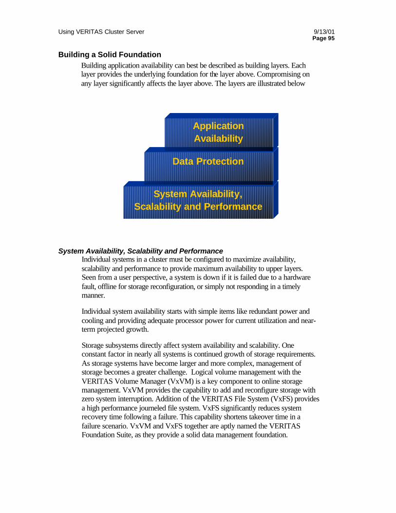
Using VERITAS Cluster Server 9/13/01 Page 95
Building a Solid Foundation Building application availability can best be described as building layers. Each layer provides the underlying foundation for the layer above. Compromising on any layer significantly affects the layer above. The layers are illustrated below
System Availability, Scalability and Performance Individual systems in a cluster must be configured to maximize availability, scalability and performance to provide maximum availability to upper layers. Seen from a user perspective, a system is down if it is failed due to a hardware fault, offline for storage reconfiguration, or simply not responding in a timely manner.
Individual system availability starts with simple items like redundant power and cooling and providing adequate processor power for current utilization and near-term projected growth.
Storage subsystems directly affect system availability and scalability. One constant factor in nearly all systems is continued growth of storage requirements. As storage systems have become larger and more complex, management of storage becomes a greater challenge. Logical volume management with the VERITAS Volume Manager (VxVM) is a key component to online storage management. VxVM provides the capability to add and reconfigure storage with zero system interruption. Addition of the VERITAS File System (VxFS) provides a high performance journeled file system. VxFS significantly reduces system recovery time following a failure. This capability shortens takeover time in a failure scenario. VxVM and VxFS together are aptly named the VERITAS Foundation Suite, as they provide a solid data management foundation.
System Availability, Scalability and Performance
Data Protection
Application Availability
Using VERITAS Cluster Server 9/13/01 Page 96
The last component is SANPoint Control. SANPoint Control simplifies management of complex Storage Area Networks by providing automatic discovery, visualization and zoning administration of SAN-connected devices.
Data Availability Data availability refers to protecting critical corporate data with a properly designed backup and recovery scheme. Proper data protection in a 24 x 7 world has become increasingly difficult to architect, and increasingly important. Crafting an architecture capable of performing backups with no impact to online operations and capable of minimum time restores is a key factor in availability. VERITAS NetBackup is the industry leader in enterprise backup. NetBackup can leverage key technologies provided by the underlying Foundation Suite to address online backup of critical data. These technologies include volume/file system snapshots, block level incremental backups, mirror break off, and others. NetBackup is further enhanced by application specific agents for major critical database packages to provide transparent database backup and recovery.
Application Availability Once the lower layers are properly addressed, a comprehensive application availability architecture can be build using the VERITAS Cluster Server. As documented in this paper, VCS is a robust, cross-platform application availability solution designed to provide a framework for controlling business critical applications.
Things to Avoid
Using Outside Name Services Using outside services for critical cluster services makes HA services contingent on the outside service. For example, using outside NIS or DNS for name resolution and other lookups can make all HA services depend on the reliability of the outside servers.
All name to IP mapping required to bring the cluster into service should be maintained locally to prevent loss of NIS or DNS causing a cluster failure For example, the hosts entry in /etc/nsswitch.conf should list files first.
If outside name service is required for admin reasons, make the service highly available!
• Primary/Secondary DNS
• NIS Master/Slave
NIS presents a larger problem, as many services beyond hostname resolution can rely on the NIS server. If NIS is an absolute requirement, several steps may be used to increase reliability of the services.
Using VERITAS Cluster Server 9/13/01 Page 97
• Make each VCS node a NIS slave server. This removes outside network issues from effecting NIS service. Updates to outside NIS masters are automatically applied to the slave servers via yppush.
• Ensure NIS slave servers exist on multiple subnets each server is connected to. In this way, loss of a single interface will not prevent access to NIS services
NFS File Service Many companies use NFS service to distribute application binaries rather than installing on each server. This presents another problem, as loss of the NFS service will render the High Availability servers far less than available. If NFS service is a corporate requirement, the customer must ensure the NFS servers themselves are highly available and all network infrastructure connecting the VCS cluster to the NFS servers is highly available as well.
Using NFS may seem like it simplifies administration, but likely adds complexity and risk to a High Availability cluster. It is recommended that application binaries be installed and maintained on the cluster servers instead to reduce risk.
Using NFS in the Cluster Using NFS within the cluster to mount file systems from one server to another is highly discouraged. Many customers attempt to “utilize both servers” by having each server NFS mount a file system exported by one system in the cluster. This technique essentially makes one server in a cluster depend on another. This dependency reduces overall cluster availability!
Using creative techniques such as loopback mounting and automounter do not resolve the basic concept that a server in a cluster may not depend on another in the cluster.
If parallel access to data is required, use an outside NFS servers, or nodes that are not part of the failover group in question A more advanced solution is the VERITAS SANPoint Foundation Suite/HA which implements a true SAN cluster file system and volume manager on Solaris.
Cluster Configuration The question “What is the recommended cluster configuration?” is often asked, yet nearly impossible to answer. There is no right or wrong answer, only “whatever best suits the customer needs”
Number of nodes The recommended number of nodes in a cluster is the most common question asked by prospective and current VCS users. It really boils down to what functionality is required. Creating a 32-node cluster simply to have 32 nodes is not worthwhile. Cluster size should be determined by application functionality.

Using VERITAS Cluster Server 9/13/01 Page 98
This means a cluster should contain enough systems to support a specific set of applications. For example, an 8 node cluster supporting 8 or 10 instances of Oracle. Adding additional nodes to support a completely unrelated Sybase configuration simply adds cluster complexity as well as increased load by the VCS daemons monitoring the resources and nodes. In a case like this, two separate clusters, each with their own purpose and both monitored via the Cluster Server Cluster Monitor GUI would be best.
On the other side of this discussion, if a service needs to be touched when another service changes state, they should be in the same cluster. For example, if a middleware application needs to be restarted when a database service is started, placing all nodes in the same cluster makes using Service Group dependencies and triggers easy.
If two clusters using different operating systems, such as NT and Solaris, or HP and Solaris need to be interrelated, this is a function of the VERITAS Global Cluster Manager. GCM allows “cross cluster event correlation”. Different operating systems may not be mixed in a single VCS cluster. But GCM can span multiple clusters of the same or different operating systems and allow an event in one cluster to trigger an action in another. For example, resetting an application running on an NT cluster when a backend database on an HP cluster is restarted. Please see www.veritas.com for more information on Global Cluster Manager.
Storage Configuration Storage Area Networks allow extreme flexibility when implementing High Availability clusters. Nodes can be added and removed with no interruption to running systems. Use of a SAN also allows creating larger failover configurations to allow cascading failover or manual load balancing between systems.


