S9081-AB-GIB-010 REVISION 1 Reliability-Centered Maintenance (RCM) Handbook This manu al sup ersedes S9081-AB-GIB-010, dated Octob er 1983, which shall b e destro yed. DISTRIBUTION STATEMENT A: APPROVED FOR PUBLIC RELEASE. DISTRIBUTION IS UNLIMITED. PUBLISHED BY DIRECTION OF COMMANDER, NAVAL SEA SYSTEMS COMMAND 0910-LP-106-031818 April 2007Downloaded from http://www.ev eryspec.com
If you require assistance, contact distance support (anchor desk) via
the web http://www.anchordesk.navy.mil/) and via the toll free number
(1-877-4-1-TOUCH [86824]).
Shi ps, t r ai ni ng act i vi t i es, suppl y poi nt s, depot s, Naval Shi pyar ds andSuper vi sors of Shi pbui l di ng ar e r equest ed t o ar r ange f or t he maxi mumpr act i cal use and eval uat i on of NAVSEA t echni cal manual s. Al l er r or s,omi ss i ons, di scr epanci es, and suggest i ons f or i mpr ovement t o NAVSEAt echni cal manual s shal l be f or war ded t o:
COMMANDERCODE 310 TMDER, BLDG 1388NAVSURFWARCENDI V NSDSA4363 MI SSI LE WAYPORT HUENEME CA 93043- 4307
on NAVSEA Techni cal Manual Def i ci ency/ Eval uat i on Report , f orm NAVSEA4160/ 1. Al l f eedback comment s shal l be t hor oughl y i nvest i gat ed andor i gi nat or s wi l l be advi sed of act i on r esul t i ng t her e f r om. Thr eecopi es of NAVSEA 4160/ 1 are i ncl uded at t he end of each separatel ybound t echni cal manual 8- 1/ 2 x 11 i nches or l ar ger . Copi es of f or mNAVSEA 4160/ 1 may be downl oaded f r om:
ht t ps: / / nsdsa2. phdnswc. navy. mi l / t mmp/ f orms/ TMDER_BLANK_REV_3- 2001. doc
Users ar e encour aged t o t r ansmi t def i ci ency submi t t al s vi a t he NavalSyst ems Data Support Act i vi t y Web page l ocat ed at :
ht t ps: / / nsdsa2. phdnswc. navy. mi l / t mder / t mder . ht m
Ur gent pr i or i t y TM def i ci enci es shal l be repor t ed by Naval message toPor t Hueneme Di vi si on, Naval Sur f ace Warf are Cent er ( Code 311) , Por tHueneme, CA. Local message handl i ng pr ocedur es shal l be used. Themessage shal l i dent i f y each TM def i ci ency by TM i dent i f i cat i on number
This handbook provides Navy maintenance practitioners a reference document for applying the
principles of Reliability-Centered Maintenance (RCM) to the evaluation of both new and well-established ship planned maintenance system (PMS) preventive maintenance requirements. It is
intended as a supplement to the Naval Sea Systems Command Reliability-Centered Maintenance-based
certification program for those who develop, modify, review and authorize Planned Maintenance Systemtasks for Navy ships, systems, and equipment. The handbook introduces basic principles of maintenance
and illustrates how these principles establish rules for good maintenance tasks. It describes how theserules are used to develop maintenance requirements and associated documentation for new systems and
equipment as well as to evaluate and improve the quality and effectiveness of well-established
maintenance programs.
Requirements for analysis of preventive maintenance requirements and for development of associated
support documentation are defined in MIL-P-24534A, “Planned Maintenance System: development ofMaintenance Requirement Cards, Maintenance Index Pages, and Associated Documentation.”
1.2 History of RCM
Logical methods for designing preventive maintenance programs started about a half century ago. This brief history sets the stage for detailed discussion of the Reliability-Centered Maintenance methodology
mandated by the Chief of Naval Operations for ship maintenance. OPNAVINST 4700.7(series)
“Maintenance Policy for U.S. Navy Ships,” and OPNAVINST 4790.4(series) Ships’ Maintenance andMaterial Management (3-M) System Policy require the use of RCM for the development of maintenance
programs and associated maintenance tasks.
Efforts to look deeply into the effectiveness of preventive maintenance as a process for avoiding failure began in the late 1950s. Those involved in establishing preventive maintenance requirements before
then may have been so convinced of the value of their actions that they saw no need to prove its truth.
They reacted almost entirely to each event as it occurred rather than to generalize their experience.
The introduction of jet aircraft fleets led the airline industry to apply a growing expertise in the process
of analysis to improving the effectiveness of preventive maintenance for transport aircraft. Since theunderlying reason for preventive maintenance is the belief that reliability of hardware decreases with
use, the first efforts examined the relationship between reliability and age (use). This was done by
application of techniques already used by life insurance actuaries.
In 1967, the airline industry’s Maintenance Steering Group (MSG) first applied decision tree logic – a
series of questions that lead to a supportable maintenance task decision – to the problem of identifying
required preventive maintenance tasks. This predecessor of RCM proved an efficient approach, since itfocused directly on the impact of unreliability on operations and safety. The following year, decision
tree logic formed the basis for design of the initial Boeing 747 maintenance program. In the ensuing
years, the airline industry updated the MSG approach and applied it to such aircraft as the Boeing 767
and beyond.
In the early 1970s, this work attracted the attention of the Office of the Secretary of Defense, the Naval
Air Systems Command, the Air Force, and the Army. The Navy was the first to apply this new
philosophy and an improved methodology called Reliability-Centered Maintenance (RCM) to both newdesign and in-service aircraft.
In 1978, United Airlines published a book prepared under contract to the Office of Assistant Secretaryof Defense (Manpower, Reserve Affairs and Logistics) detailing the RCM methodology. This book, Reliability-Centered Maintenance by Stanley Nowlan and Howard Heap and the work leading to its
publication formed the basis for the Naval Sea Systems Command application of RCM to shipmaintenance.
The prototype application of RCM to surface ship preventive maintenance was installed in USSROARK (FF-1053) in 1978. Following evaluation of results on four additional FF-1052 class ships, the
Chief of Naval Operations directed that RCM be used for development of scheduled maintenance tasksfor all new and in-service naval ships in accordance with MIL-P-24534A, Planned Maintenance System.
This application is now called “Classic RCM.”
The principles of RCM were also applied to ship depot level maintenance in the Phased Maintenance
Program (PMP) developed initially for Combat Support Ships in the early 1980s. This program, whichwas later expanded to all auxiliary ships, amphibious ships and certain combatant ships, served as the
catalyst for Continuous Maintenance (CM). CM is a nearly continuous process of identifying,
screening, authorizing, planning, and accomplishing maintenance at all maintenance levels(organizational, intermediate, and depot). The underlying policy for both PMP and CM is called
Condition-Based Maintenance (CBM), which is the CNO’s policy for ship maintenance as called out inOPNAVINST 4700.7(series). CBM is defined as maintenance based on objective evidence of need.
OPNAVINST 4790.16, “Condition-Based Maintenance Policy,” requires use of RCM to determine
evidence needed to select appropriate maintenance.
Benefits derived from the use of RCM to establish maintenance programs eroded over the years because
the Navy tended to overlook an important part of the RCM process – periodic analysis of operational
and maintenance feedback to continuously improve the periodicity and scope of prescribed maintenancetasks. This became critical in the 1990s, when construction of new ships fell prey to the cost of
maintaining in-service ships.
Recognizing that adopting change based on operating experience is a major component and benefit of
RCM, the Naval Sea Systems Command developed an RCM methodology to be used to improve
existing preventive maintenance programs in 1996. A prototype of the so-called RCM ‘Backfit’Methodology was applied to the USS YORKTOWN (CG-48) Planned Maintenance System (PMS) as
part of the Smart Ship Program. Results included a 46.7 percent reduction in ship’s force PMS
workload without adverse impact on safety, mission, or the environment. This approach has beenrefined and is applied to all shipboard systems by Navy In-Service Engineers (ISEs) in conjunction with
ship’s force personnel experienced in operation and maintenance of the systems evaluated. Both the
ISEs and involved ship’s force personnel are provided training in Backfit RCM prior to conducting their
analyses of existing PMS tasks during an evaluation called Ship Maintenance Effectiveness Review(SHIPMER).
This handbook addresses both the ‘Classic’ RCM approach for development of new maintenance
requirements for systems and equipment and the RCM ‘Backfit’ approach for validation of maintenancerequirements for in-service systems and equipment.
1.3 Basis for RCM
RCM is derived from careful consideration of basic questions such as the following:
• What functions does the system perform?
• What functional failures might occur?
• Which of the functional failures are likely to occur?
• Are the functional failures evident to the operating crew?
• What are the consequences of failure on safety, mission, and cost?
• What is the relative risk of failure in terms of probability of failure and severity of failure?
• What, if anything, can be done to prevent likely failures?
• What is the cost of trying to prevent failures?
RCM is reliability-centered. Its objective is to maintain the inherent reliability of the system orequipment design, recognizing that changes in inherent reliability may be achieved only through design
changes. Within this constraint, RCM functions to determine what preventive maintenance is requiredto:
• Ensure safety of personnel, protect the environment and equipment; and
• Provide reasonable assurance of being able to accomplish the ship’s mission at a cost less thanthat of correcting the failure the preventive task is trying to prevent.
Classic RCM develops maintenance tasks for new systems by:
• Partitioning the ship into systems and subsystems that require analysis;
• Identifying functionally significant items;
• Determining any needed maintenance requirements (tasks) for each significant item based onanalysis of its functions (both evident and hidden), its dominant failure modes, and management
of risk associated with functional failure;
• Determining when, how, and by whom each task should be accomplished; and
• Identifying any need for design change:
– When safety is threatened by a failure for which there is no applicable and effective
preventive task, or – When inherent reliability proves to be less than adequate.
Backfit RCM validates existing maintenance tasks by using information from operations and
maintenance in a streamlined analysis, and adjusting task intervals and task content where appropriate.
The identification and application of fundamental maintenance concepts (e.g., risk management) provides the maintenance practitioner a foundation for future application.
The Chief of Naval Operations (CNO) has mandated that Condition-Based Maintenance (CBM) practices be implemented in all Navy maintenance decisions involving ships, aircraft, and infrastructure
in OPNAVINST 4790.16. The instruction tasks NAVSEA to “provide procedures and training for the
implementation of CBM…." The objective of condition based maintenance is that maintenance is performed based on objective evidence of the need. Reliability Centered Maintenance (RCM) is the
process that is used to develop the maintenance tasks needed to implement CBM. To achieve the
CNO’s CBM goal, NAVSEA 04RM established the RCM Certification Program. The Naval SeaSystems Command certifies all those who develop, review, or approve scheduled maintenance
requirements to ensure that RCM principles and approved methodology are properly employed in
maintenance plan development for Organizational, Intermediate, and Depot (OI&D) levels. RCMcertification is required for all PMS practitioners in accordance with Appendix J of NAVSEAINST
4790.8(series), Ship’s Maintenance and Material Management (3-M) Manual. NAVSEA 04RM
manages the RCM Certification Program and associated training.
Each equipment system placed in a U.S. Navy ship has an experienced shore-based In-Service Engineer(ISE) responsible for monitoring lifecycle as well as individual problems in that system. The RCM
Certification Program affects all individuals who either develop new PMS, or make changes to existingPMS. Those persons, whether they are Navy employees or contractors must achieve and maintain the
appropriate level of RCM certification relevant to the work they are performing.
ISEs are challenged daily with design and maintenance issues. NAVSEA’s RCM Certification Program
ensures that they are equipped with the skills required to develop, review or approve changes to PMS.
RCM Certification comprises three certification levels.
Level I - Backfit RCM for Practitioners: Level I certification is required for ISEs, Commodity
Specialists or contractors who modify existing Planned Maintenance System (PMS) maintenance tasks.The course is two days in duration and taught by an approved SEA 04RM instructor. This course
provides training in the fundamental CBM topics and methodologies to be employed when performing
an engineering review of existing PMS maintenance tasks. Upon completing certification, individualsapply this methodology to every maintenance related assessment they perform. Level I certification is
valid for three years and can be renewed by attending another Level I training class, a Ship Maintenance
Effectiveness Review (SHIPMER) session, or by satisfactorily completing an online recertificationexamination.
Level II – Classic RCM for PMS Requirement Developers: Level II certification applies to ISEs,Commodity Specialists or contractors who develop or approve maintenance requirements for new
systems or equipment. The course begins with an introduction to maintenance engineering and RCMfundamentals and leads to detailed instruction in the MIL-P-24534A (Navy) process for developing
maintenance task requirements for Navy equipment. The student is guided through multiple practical
application examples to further illustrate the RCM process and to prepare for the certification
examination. The course is five days in duration and taught by an approved NAVSEA 04RM instructor.Level II certification is valid for three years and can be renewed by attending another Level II training
class or by satisfactorily completing an online recertification examination.
Level III – Navy Backfit RCM Trainer: Level III certification applies to a very small number of ISEswho have been selected to teach the Level I certification course within their command or activity.
Individuals selected for Level III training must be certified in both Level I and Level II and demonstrate
a high level of proficiency in RCM as outlined in MIL-P-24534A (Navy). The Level III course iscomposed of two major elements and is two weeks in duration. The first week is devoted to an intensive
review of RCM theory and application including a comprehensive examination of RCM fundamentals
and instructor oriented training in the RCM Level I curriculum. The second week is an introductorycourse on adult training techniques and includes opportunity to practice the presentation of the RCM
Level I course material in a controlled environment. Level III certification requires the demonstration of
instruction proficiency of the RCM Level I course material and is valid for one year. Renewal ofcertification is contingent upon successful demonstration of continued proficiency to NAVSEA 04RM
or designated technical warrant holder.
1.5 Summary
In 1967 the airline industry’s Maintenance Steering Group (MSG) applied the first decision logic tree
for development of preventive maintenance. This work grew out of a comprehensive review ofmaintenance practices begun in the late 1950s. By the 1970s, a systematic approach for the
development of maintenance had become known as “Reliability-Centered Maintenance” (RCM). The
fundamental goals of RCM were to maintain system functionality by ensuring all maintenance actionswere designed to maximize system reliability at minimum cost. To accomplish this, the RCM process is
a structured approach that requires the analyst to justify maintenance requirements by answering a seriesof questions.
• What functions does the system perform?
• What functional failures might occur?
• Which of the functional failures are likely to occur?
• Are the functional failures evident to the operating crew?
• What are the consequences of failure on safety, mission, and cost?
• What is the relative risk of failure in terms of probability of failure and severity of failure?
• What, if anything, can be done to prevent likely failures?
• What is the cost of trying to prevent failures?
The US Navy began applying RCM to surface ship maintenance in 1978. Within a few decades RCMhas become a fundamental part of the Navy’s Conditioned Based Maintenance (CBM) Policy. Toensure RCM principles are understood and applied across all maintenance decisions during a ship’s
entire life cycle, Naval Sea Systems Command has instituted a certification program. All personnel
associated with the development, review, or approval of scheduled maintenance requirements arerequired to undergo training in RCM fundamentals as they apply to existing maintenance (Level I) or
Section 2―Fundamentals of Maintenance Engineering (ME)
This section briefly explains nine fundamental maintenance concepts that govern the development,implementation, execution, and continuous improvement of ship maintenance programs. These are core
principles of RCM. These nine fundamental concepts are:
• Failures happen.
• Not all failures have the same probability
• Not all failures have the same consequences
• Simple components wear out, complex systems break down
• Good maintenance provides required functionality for lowest practicable cost
• Maintenance can only achieve inherent design reliability
• Hidden functions require special treatment
• Unnecessary maintenance takes resources away from necessary maintenance
• Good maintenance programs undergo continuous improvement.
These concepts form a progression of maintenance engineering thought from the most fundamental
concept ⎯ failures happen ⎯ to the greatest challenge for any maintenance program: establishment of a process for continuous improvement.
2.1 Failures Happen
It is appropriate to begin discussion with the fact that functional failures -- unsatisfactory conditions in
which intended functions are not adequately provided -- happen.
Maintenance planners know intuitively, if not by personal experience, that unexpected failures happen.
Nevertheless, they tend to approach the business of maintenance program planning from one of two very
different directions. One direction is to attempt to eliminate all failures. The second direction is risk
management. There are many factors in equipment reliability that can cause a failure. They includestress, corrosion and fatigue. A maintenance program can be used to prevent or preclude such failures.
However, there are failures caused by things beyond the control of the maintainer. These include
unplanned or random events (sudden high-energy impact, lightning strike, etc.), sometimes called acts ofGod. There is nothing that can be done to prevent these failures, especially from an economic
standpoint. There are failures caused by poor manufacturing quality. These types of failures cannot be
prevented by maintenance.
We know that not all failures can be prevented. Good maintenance programs don’t try to prevent all
failures; they couldn’t if they tried! Good maintenance programs will minimize the number of failures,
however, perhaps even to the point where they appear to have been totally eliminated.The paradigm of attempting to prevent all failures has lead to extremely costly maintenance programs
that do not succeed because all failures cannot be prevented. The important thing is to focus resources
Reliability engineers define reliability as the probability that equipment will provide its desired function
over a specified period of time. When maintainers speak of probability of failure, they really mean the
rate at which a piece of equipment will fail over a period of time, i.e. the frequency, or rate, of failure.
Things to consider about probability of failure are: Is that probability, or rate, of failure a function oftime? Is it increasing in frequency? (a bad thing), Is it decreasing in frequency? (a good thing), or is it
constant. A constant failure rate is often called random failures. It is often said that complex equipment
experiences random failures. So how do real-world equipment failure rates compare to our preconceivednotions about probability of failure?
The pioneering work on Reliability-Centered Maintenance performed by United Airlines began with astudy of hardware age-reliability characteristics. When United disassembled engines for repair, it found
some engines whose internal components were in good condition and some engines whose internal
components were in poor condition. Further, when United began to explore the age-reliabilityrelationship by introducing these engines back into service after minimal repair, it found that some
engines with internal components in good condition exhibited lower reliability in service than engineswith components in worn condition. United realized that it did not have as firm a grip on the
relationship between time in service (or “age”) and reliability as it thought. Reliability degradation is areduction of an item’s resistance to failure.
United Airlines applied the same technique used by insurance actuaries when developing mortalitycurves for human beings. This technique was used to explore the relationship between the failure-rate orconditional probability of failure and some measure of operating age for aircraft hardware. The
conditional probability of failure is the failure rate of the component with respect to time. A constantconditional probability of failure means that the failure rate is not increasing or decreasing with respect
to time, it means that we have random failures.
The results of United’s initial exploration of this relationship are shown in Figure 2.1 in column marked
UAL, which were developed from a study of 139 aircraft components and equipment. These resultsshow both wear out (age-related failures, curves A, B, and C) and random failures (curves D, E, and F).
The figure also includes similar results from later studies.
1. Random failures predominate compared to age-related failures. Infant mortality (i.e., high initial probability of failure, decreasing with age) is common.
2. Infant mortality persists (significant time is required to transition out of infant mortality to steadystate conditional probability of failure).
3. The conditional probability of failure is never zero.
4. The shape of the age-reliability characteristic curve is highly configuration-dependent.5. Simple items tend to exhibit wear out (curves A, B and C) whereas complex items tend to exhibit
random failures (curves D, E and F).
Curves D, E, and F should not be interpreted to mean that some items never degrade or wear out. Thesecurves simply show the life of some items came to an end before wear out was evident, perhaps because
they were removed for restoration, or were replaced with modified or upgraded items. Everything will
eventually degrade with time, but some items degrade so slowly that wear out is not a concern since the
degradation will not adversely affect performance during the life of the ship. Degradation of the glass inthe bridge windows, for example, does not trouble the maintenance planner, who needs to focus on
items whose degradation is of real concern.
Age-reliability characteristics curves can tell a maintenance planner whether or not wear out (increase in
the conditional probability of failure) exists. If there is no evidence of wear out, there
is no good basis for a time-directed life-renewal task. It makes no sense to spend maintenance resources
to renew the life of an item whose reliability has not degraded or which may have actually improvedwith age.
It is not necessary to develop age-reliability characteristics curves for every item of equipment. In fact,
these curves should be limited to a small set of high-value items where the investment cost of curvedevelopment will be returned in reduced life-cycle maintenance requirements. Maintenance planners
need to keep these curves ⎯ and the lessons they teach ⎯ in mind as they review maintenance for theitems for which they are responsible.
Rapid increase in the conditional probability of failure of an item may be associated with a component,
subassembly, or assembly within an item ⎯ or it may be typical of the complete item. The more
complex an item, the less likely it is that all its constituent elements will have the same age-to-failurecharacteristics.
2.3 Not All Failures have the Same Consequences
Maintenance is an investment, an indirect cost that organizations are willing to bear with the expectation
they will receive a benefit in the form of sustained personnel safety and system reliability that exceedsthe magnitude of their investment. The consequence of failure of an item is a very important
consideration when considering appropriate levels of maintenance. In RCM we refer to the consequence
as severity of failure.
We saw in Section 2.2 that the conditional probability of failure is never zero. Because there is always a
chance of a component or a system failing, the severity of that failure is very important. It is also
important not merely to focus on what happens to a component when it fails, but what happens at higherlevels. Severity should be considered at the highest level, i.e. what happens to the ship when the
component fails? A good example is a bearing in a ship’s fire pump. If the bearing fails, we know thatwe will need a replacement. An immediate reaction would be to consider this a critical failure, but we
must look at the overall effects. How many fire pumps are onboard and how many are required for
system pressure? i.e. How much redundancy is there? Is there a cross connect from the seawater servicesystem? It is important for the analyst to consider the overall effect to the ship, to see the big picture.
The consequence of any failure may be categorized as impacting Personnel, Safety, Ship Mission andAll Others. Obviously, the highest level of severity is a Sailor being injured or killed; this is a Safety
related failure. The next level down in importance is the Mission level. Will the failure affect the
mission of the ship? If the failure does not affect safety or mission, than it falls into the “all others”
category and preventing the failure is primarily an economic decision; the cost of doing the preventive
maintenance must be less than the cost of correcting the failure that the maintenance is trying to prevent.It is important to recognize that not every failure results in death or injury; not every failure will impact
the ship’s ability to perform its mission. As a result, we must always make a realistic assessment ofeach failure’s consequences. The probability and the severity of a failure factor into the concept of risk .
Everyone involved with maintenance should understand the fundamental concepts of risk in order todeal with it objectively and effectively. Maintenance practitioners need to know what risk is, how it can
be assessed, and how it can be managed as part of a sound maintenance program.
Most people asked to define “risk” identify it as a threat, a hazard, or a very undesirable situation. Theyclearly associate “risk” with adverse circumstances. This may be correct, but it presents only one aspect
of risk.
Risk is composed of two factors: the probability of failure (P f ) of an item and the severity of failureconsequences (Sf ). Thus, from a mathematical perspective:
This definition of risk is very important. The natural tendency is to focus on the severity of failure, but
not all potentially adverse failures are likely to occur.
The probability of a failure is at least as important a consideration in the objective assessment of its risk
as is failure severity. The design of a well-balanced and effective maintenance program requires that
both these factors be considered. Neglecting Sf could result in overlooking needed coverage for a failuremode that could injure or kill a member of the operating crew, damage the environment, or cause loss of
a critical mission capability. Neglecting Pf could result in the unnecessary expenditure of resources to
“prevent” a failure that may never occur.
A well-designed maintenance program uses the concept of risk to allocate resources where they will
provide the greatest benefit. It assesses the risk of failure that confronts individual ship systems andequipment, and it allocates resources to prevent failure on the basis of that risk assessment. It
recognizes the “opportunity cost” of each maintenance decision: unnecessary maintenance that reduces
resources available to accomplish needed work in other areas that must then be deferred for lack ofresources.
Now that we know what “risk” is, we need some way to evaluate or assess it. We can begin by looking
at dominant failures modes.
Dominant failure modes occur frequently or have serious consequences
There are two specific considerations used to identify dominant failure modes:
• First, the failure mode should appear relatively often in material condition analyses. It should
constitute a relatively large proportion of the total number of failures, or it should appear insignificantly degraded condition in a large proportion of diagnostic tests or inspections. The
sample size must be adequate to establish confidence in the results.
• Second, a failure that does actually occur should be considered dominant if it has seriousconsequences, regardless of frequency of occurrence. Serious consequences could be such
things as personnel injury or death, loss of mission capability, or expensive repairs.
A 19th
century Italian economist named Pareto once stated that 20 percent of Italy’s population
controlled 80% of the nation’s wealth. This became known as the Pareto Principle, and has many
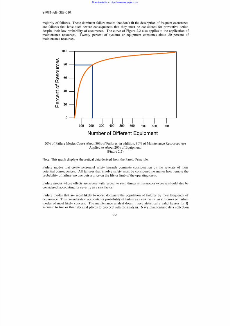
applications, including maintenance. As shown in Figure 2.2, dominant failure modes account for the
majority of failures. Those dominant failure modes that don’t fit the description of frequent occurrence
are failures that have such severe consequences that they must be considered for preventive actiondespite their low probability of occurrence. The curve of Figure 2.2 also applies to the application of
maintenance resources. Twenty percent of systems or equipment consumes about 80 percent of
maintenance resources.
100
80
60
40
20
0
100 200 300 400 500 600
Number of Different Equipment
P e r c e n t o
f R e s o u r c e s
700 900800
20% of Failure Modes Cause About 80% of Failures; in addition, 80% of Maintenance Resources AreApplied to About 20% of Equipment.
(Figure 2.2)
Note: This graph displays theoretical data derived from the Pareto Principle.
Failure modes that create personnel safety hazards dominate consideration by the severity of their
potential consequences. All failures that involve safety must be considered no matter how remote the
probability of failure: no one puts a price on the life or limb of the operating crew.
Failure modes whose effects are severe with respect to such things as mission or expense should also be
considered, accounting for severity as a risk factor.
Failure modes that are most likely to occur dominate the population of failures by their frequency of
occurrence. This consideration accounts for probability of failure as a risk factor, as it focuses on failure
modes of most likely concern. The maintenance analyst doesn’t need statistically valid figures for Pf
accurate to two or three decimal places to proceed with the analysis. Navy maintenance data collection
and analysis systems have not yet reached the point where discrete, widely accepted values for system
and equipment Pf are available. Fortunately, broad or general values for Pf can and should be used untilmore detailed figures are developed. Even the use of such broad values of Pf permits comparing the
relative risk of different work items where tradeoff decisions involving funding must be made.
Next, we consider the second element of risk assessment: severity of failure.
The Classic RCM analysis process evaluates the severity of failure at three different levels.
The first step is the component level, which is an evaluation of failure severity at the local (or
equipment) level. The principal concern at this point is whether the failure mode will cause injury or
death to operating personnel in the vicinity at the time of failure. A secondary concern at the local levelis whether the failure will cause complete loss of the equipment, i.e., require rebuild or replacement of
the equipment or simply replacement of a component. The answer has implications for material
procurement and corrective effort.
The next step, the subsystem/system level, is to examine severity of failure within the system boundaries. The concern here is loss of system functionality, including safety issues related to loss of
function. Some systems have redundant subsystems; loss of one subsystem has no immediate systemimpact, thereby reducing the severity of failure. The steering system is one example of this, as it has
both port and starboard subsystems. Loss of one side is compensated for by operation of the other.
The final step examines severity of failure outside the bounds of the system. The concern here is loss of
mission capability. Ship systems are the basic building blocks of ship mission capabilities; loss of a ship
system can mean loss or significant degradation of a mission capability. The effect of failure on shipmission capability can be highly varied. Loss of the electronic countermeasures system may jeopardize
the ship in a combat situation, but loss of the potable drinking water system will put the ship out of business in any situation.
So failures have different consequences: safety or regulatory, mission, and economic. The maintenanceanalyst and the maintenance planner must evaluate these consequences to determine the exact nature of
severity of failure as it relates to risk.
Both risk factors, Pf and Sf, are considered in the decision to either conduct a risk management analysisor to eliminate it as a source of concern. If in doubt, the default decision is to carry the functional failure
and the failure mode forward for analysis. The entire purpose of risk assessment is to decide whether to
eliminate failures of little significance from further preventive maintenance analysis.
We recognize that it simply is not possible to prevent all failures. Further, it is not even worthwhile to
prevent all failures. It is possible to reduce the number of failures to an acceptable level and then tomanage the risk assessment of that small number. That is what good maintenance is all about.
Excessive maintenance that attempts to prevent all failures does not fit the definition of “good
2.4 Simple Components Wear Out, Complex Systems Break Down
This was mentioned briefly in the previous discussion on age-reliability curves, but we will now discuss
this concept in greater detail. A “simple” component is something that has relatively few failure modes.
Some examples are the timing belt in an automobile, the roller bearing on a drive shaft, the cable on a
crane. Simple items often exhibit some particular sign of distress before they fail (i.e., they provideevidence of potential failure). For example, a radiator hose in your car most often fails by rupturing. A
soft or bulged hose is an indication that failure is near. For such failures, a knowledgeable planner can
often design a task to detect the evidence of potential failure and take corrective action prior to failure.When we say “wear out,” we mean that there is a marked increase in the conditional probability of
failure. As can be seen in Figure 2.1, the conditional probability of failure for curves A and B show this.
In each case, the conditional probability of failure has a “wear out” age. If the maintenance plannerknows the typical wear out age for a component, it is easy to develop a schedule to replace the
component before failure.
Complex items tend to breakdown through random failure. Complex items contain many simple
components, each having its own failure modes. Because there are so many components in a complexitem, no single failure mode tends to dominate. Because complex items have a large variety of failure
modes, they typically do not exhibit a wear out age. Their failures do not tend to be a function of age.Failures of complex systems most often occur randomly. Their conditional probability of failure is
generally a constant. These constant conditional probability of failure equipments are represented by
curves E and F in Figure 2.1.
These differences between simple and complex components are important with respect to maintenance
strategies. Because we do not have a wear out age for complex items, the practice of performing time-
driven overhauls on such items is wasteful of resources. One spends money fixing things that do not
need to be fixed! Only when we can show that an item exhibits a wear out age does performing anoverhaul or replacement of that component at a particular time or age make sense.
2.5 Good maintenance provides required functionality for lowest practicable cost
We previously defined maintenance as action to ensure that items provide their intended functions when
required. Good maintenance, therefore, serves to maintain or restore function.
Our definition of maintenance is helpful but does not help the analyst or manager to differentiate good
maintenance from other maintenance. To do that, the analyst needs to evaluate the cost of performing
preventive maintenance against the cost and other consequences of not performing the maintenance. Agood maintenance program delivers required system, subsystem, and equipment functions for least cost,
i.e., least total expenditure of resources.
The statement that “good” maintenance delivers “required” functionality means that it delivers functions
essential for satisfactory operation when they are needed. Good maintenance satisfies actual, but not
necessarily theoretical, demands.
The essential nature of good maintenance is to ensure that the hardware does what is required of it when
required, not that it be wholly capable of achieving its full design capability at all times.
Hardware may be capable of doing much more than what is required of it. Maintenance efforts to
ensure that hardware produces greater capability than needed are a waste of resources. We do not
maintain our automobiles so they are capable of running at their maximum rated speed every day; we
maintain them so they will deliver normal driving speeds. Cost effective maintenance serves to preserve
the functions required by the user.
2.6 Maintenance Can Only Achieve Inherent Design Reliability
A very important point to consider about maintenance and design capability is that maintenance can
only restore or preserve the hardware’s inherent design reliability and performance characteristics. If
the design’s inherent reliability or performance is poor, doing more maintenance will not help. Toimprove poor reliability or performance attributable to inadequate design, one must change the design.
Systems and equipment do not always have to “look like the blueprint” or meet design specifications todeliver required functionality. There is no need to invest maintenance resources to attain greater
performance than needed. The design engineer typically incorporates various margins in the designspecifications. These margins provide protection from such conditions as corrosion and erosion in the
operating environment and abnormal levels of stress from performance outside prescribed operatingranges. They also take into account dimensional variations from manufacturing processes, differences
in the material composition of constituent parts that comprise the complete item, and other factors. In
addition, functional performance parameters, such as pump pressure and throughput, required by procurement specifications or available in commercial off the shelf (COTS) equipment may be greater
than required for adequate system performance. The shipbuilder may select an available 250 gpm
pump, for example, rather than procure a new pump design to provide 225 gpm required by designspecifications.
2.7 Hidden Functions Require Special Treatment
We must now ask the question, what is a hidden function, and why does it require special treatment?Some organizations perform mostly corrective maintenance, i.e. fix-when-fail, opting not to take
equipment offline to perform preventive maintenance. But what happens when you have a failure that is
not visible or evident to the operating crew? For example, an emergency device like a fire sprinkler
system, alarm system, or an overspeed shutdown device may have failed. How will you know whetherthose devices have failed until such time as their function is required?
The answer is that you will not know about a hidden functional failure until it is too late, unless you perform a procedure to test for that hidden failure.
A maintenance task to find a hidden failure, a failure finding task, does not actually prevent that failure.It seeks to find a failure that has already happened that you do not know about. The rest is
troubleshooting and corrective maintenance. The goal is to find that failure before it becomes a larger
problem. For example, you don’t want to find out your smoke detector has failed by discovering youhave an out of control fire in your home. You don’t want to find out that your boiler safety relief valve
has failed by the fact that your boiler has just ruptured. You do the failure finding test to help ensure the
availability of those protective or safety devices when they are needed.
What failure finding tasks do prevent are multiple or cascading failures. Cascading failures have a very
small probability of occurring because they depend upon several events, each with its own probabilityhappening at the same time. For example, even though they have a small probability of failure, some
cascading failures are worth trying to prevent because their consequences are so severe. Most people
will agree it is good to inspect for hidden failures that involve safety or mission consequences.
However, it must be understood that the very act of testing some safety or protective devices causesundue wear on them and may result in premature failure. For maintenance associated with hidden
failures, it is important to consider not only the consequence of failure, but the consequence of over-
testing.
2.8 Unnecessary maintenance takes resources away from necessary maintenance
There is almost always more maintenance to do than resources to do it with. If one wastes resources
doing unnecessary maintenance, there won’t be enough available to perform the truly necessary
maintenance. Inadequate investment in maintenance has adverse consequences. It is not difficult tounderstand that deferring or eliminating valid maintenance will increase an item’s probability of failure.
On the other hand, excessive investment in maintenance also has adverse consequences. There areseveral ways this takes place.
First, many maintenance actions require systems or equipment to be off-line when maintenance is performed. Every minute an item is off-line for maintenance is a minute not available for operations.
This time off-line penalizes the ship with decreased operational availability (Ao).
Second, some maintenance actions induce “infant mortality” [i.e., increased conditional probability offailure after maintenance] as a result of such factors as human error, the use of defective material, or
errors in technical documentation. If the maintenance were not mandated, there would not be the
exposure to infant mortality and no penalty in decreased operational availability would result.
Third, excessive maintenance requirements may result in maintenance accomplishment that is lessthorough than required because maintainers don't have the time necessary to accomplish all tasks
properly. This can also occur when maintenance personnel don’t believe in the value of the tasks they
are performing and perform tasks in a superficial manner. The odds of performing maintenance properly increase when maintainers are convinced of its intrinsic value.
Fourth, an adverse mismatch between maintenance task workload and maintenance manpower availablemay present the work center supervisor aboard ship a difficult choice:
• Perform every task as best as possible with the manpower available, taking shortcuts where
necessary but “accomplishing” every task;• Perform some tasks thoroughly with no shortcuts and defer the remainder; or
• Some combination of the two.
Thus, too much maintenance is not necessarily a better situation than not enough maintenance. The
most desirable maintenance program matches the investment of resources to the priority of requirements
as closely as possible. This approach provides the most effective use of maintenance resources to
achieve necessary operational availability for any level of maintenance resource allocation.
2.9 Good Maintenance Programs undergo Continuous Improvement
The most effective maintenance programs are dynamic: they are changing and improving regularly to
make ever better use of resources the longer they are in operation. They regularly test and explore the
boundaries of maintenance, obtaining increasing knowledge of the items being maintained as they
proceed, while accepting unexpected failures as the price of progress.
The Navy in peacetime should be a laboratory for the Navy at war. The Navy in peacetime should learn
all it can about system and equipment failure and the effectiveness of maintenance tasks so that theselessons are available for use in war. Operational commanders need the greatest possible flexibility for
decisions in war to have the greatest opportunity for success in combat. This includes maintenance.
Many different types of changes can be recommended to effect improvement, but improvement should
not stop with the first change recommendation. Well-designed and well-managed maintenance programs
continue to push the limits of tasks that already meet the basic criteria for applicability andeffectiveness.
Extending the periodicity of an oil change from 3,000 miles to 6,000 miles can save money. Such action
increases the value of a task by reducing its cost without affecting reliability. But what if the oil willactually provide satisfactory service for 7,500 or 10,000 miles? Ending the exploration of the limits of
lubricating oil quality at 6,000 miles would miss the greater benefit that could have been gained from
further exploration.
The highly effective maintenance manager will keep two maintenance improvement considerations in
mind. The first consideration is a short priority list of initiatives that may be used to improvemaintenance task effectiveness. The second is a hierarchy of different data analysis efforts that may be
used to focus the priority of data collection efforts.
Not all improvement initiatives have the same potential payoff leverage. The wise maintenance
manager will seek out opportunities to obtain the greatest leverage. Similarly, not all data have the same
value. The wise maintenance manager will structure data collection, analysis, and display capabilities togive the most necessary information for continuing to make improvement while operating safely and
reliably.
Priorities for different maintenance improvement initiatives
Not all maintenance improvement initiatives have the same leverage.
Eliminating unnecessary maintenance tasks has the highest potential leverage. This action eliminatesmaintenance labor, direct and indirect material, and the administrative burden of scheduling, managing,
and reporting on maintenance accomplishment.
The next highest potential leverage initiative is action to change time-directed life-renewal tasks into
condition-directed tasks.
Another improvement initiative involves analytical or empirical age exploration: extending task
periodicity based on data analysis results, operator and maintainer experience, or good engineering
judgment and then observing the results. The shorter the current periodicity, the greater the leverage is
from a recommendation to extend periodicity. Adjusting a daily periodicity to a weekly periodicityreduces required PMS workload for that task by more than 80%. This is not the only way to improve a
task, but it may be the simplest and often the most effective improvement to make.
A variety of other alternatives follows: reducing the scope of a task, using a sampling process toestimate condition in lieu of conducting 100% inspection, changing calendar-based task scheduling to
situational scheduling, and so forth.
When the maintenance manager understands the differences in improvement leverage provided with
different alternatives, he or she can focus on approaches that can provide the greatest potential payback
for an investment in change management.
Maintenance data requirements
Just as various failures do not have the same consequences, not all data have the same value. The highly
effective maintenance manager will organize data collection and analysis to identify and take advantageof data with the greatest value.
Data with the greatest value to the maintenance manager are those related to critical events: failures or
condition measurements that relate to events that affect personnel safety, protection of the environment,
or ship mission capability. Some data are critical:
• Critical data must not be overlooked or otherwise missed because critical safety or missioncapability requirements are involved;
• Critical data must be displayed to decision makers quickly (i.e., as soon as practicable after theyare “captured” or processed); and
•
Critical data must be recorded accurately and comprehensively, in a machinery history or similardatabase for future reference.
It is no trivial exercise to identify these data. Unless they are carefully identified, however, and provisions made for their comprehensive and accurate capture, analysis, and display, the maintenance
manager will be inclined to make decisions based on folklore and mythology as well as facts.
Therefore, the requirements must be identified first and then the system to support them can be designedand implemented.
Data needed to develop specific failure rates have the next greatest value. The maintenance manager
may not be interested in the failure rate of the food mixer but will certainly be interested in the failure
rate of sensors, main propulsion items, or primary weapons systems components, for example.Condition measurement data can be used to develop material condition trends, and be used to help
predict and improve failure rates.
Finally, some data may be needed to develop age-reliability characteristics curves to evaluate the
effectiveness of selected maintenance actions, principally life-renewal tasks. The development of thesecurves is time-consuming and expensive; they should only be developed where reasonable expectation
exists that they will reduce maintenance costs to an extent that more than offsets the cost of their
Regardless of the merit of specific improvement actions taken by individual maintenance managers, themessage for all maintenance managers is to ensure continuous maintenance improvement. The ongoing
process of developing, implementing, and following up on the results of an improvement program is
essential for well-run maintenance.
2.10 Summary
A thorough understanding of the nine fundamental concepts of maintenance engineering…
• Failures happen
• Not all failures have the same probability
• Not all failures have the same consequences
• Simple components wear out, complex systems break down
• Good maintenance provides required functionality for lowest practicable cost
• Maintenance can only achieve inherent design reliability
• Hidden functions require special treatment• Unnecessary maintenance takes resources away from necessary maintenance
• Good maintenance programs undergo continuous improvement
… is vital to development, implementation, execution, and continuous improvement of an effective
It is important that we now consider, from the viewpoint of RCM, all the elements that comprise whatwe call “maintenance” by asking the question: “What is maintenance?”
Why would we ask such a fundamental question? Very simply, to ensure that we all have the sameunderstanding of what maintenance actually accomplishes. If maintenance practitioners have different
ideas of what maintenance is, they will also have different ideas of what it should accomplish. It would
thus be very difficult to achieve a common approach to maintenance program design and executionacross the Navy maintenance community. As a consequence, this handbook now begins a detailed
examination of maintenance by establishing that foundation.
3.1 Definition of Maintenance
Let’s review the Navy’s definitions of “maintenance”
The Navy’s Maintenance and Material Management (3M) Manual NAVSEAINST 4790.8(series)defines maintenance as:
“Actions taken to ensure that systems, equipments and components
provide their intended function when required.”
Recalling the reasons one does maintenance, listed in Section 2.2, the top-level objective for a
maintenance program can be stated as restoring or preserving reliability for minimum cost. Without a
common understanding of what maintenance is, the paths taken to achieve that objective may differ,especially if they are built on folklore rather than on well-established concepts of maintenance
engineering. The results can be confusion in maintenance terminology and the development ofinapplicable or ineffective maintenance tasks and task intervals.
In this book, we use the following definition:
Maintenance is the set of actions taken to ensure that systems,
equipments and components provide their intended functions when
required.
There are a few points worth emphasizing about this definition.
First, the primary focus of this definition is on maintaining the intended function of an item rather than
its design performance. Many designs provide excess performance capacity or endurance as an inherent
characteristic of the design. E.g., the pump selected for a system may be rated at 100 gpm when thesystem design requirement is only 75 gpm. Maintenance that is oriented to sustaining excess capability
not needed for operations expends resources without benefit. This is not good maintenance practice.
Next, this definition requires the function being maintained to be available when it is required. Since
certain functions, such as weapons firing and overpressure relief, may not be required continuously,there may be a need to verify their availability.
Finally, the terms “component, equipment, and systems” as used in this definition apply to hardware at
the particular level where the analysis is being performed. This may be a system, a subsystem,equipment, or a component, depending on the specific preventive maintenance task being examined.
This definition also forms the basis for the definition of functional failure:
Functional failure is an unsatisfactory condition in which intended
functions are not adequately provided.
The manner in which functional failure is discerned is dependent on what type of function is involved.
There are several classifications of function:
• Active functions require activity of an item; e.g., a pump provides liquid flow.
• Passive functions are not related to activity; e.g., a pump contains the working fluid.
• On-line functions are continuously provided during normal operations; e.g., distribution
of electrical power.
• Off-line functions are not continuously provided e.g., inflation of a life jacket or firing amissile. Usually, they are activated by some infrequent action or event.
• Evident functions are those whose loss is observable by the crew during their normaloperating routine; e.g., loss of refrigerant flow causes an increase in refrigerated space
temperature.
• Hidden functions are not observable by the crew during normal operations. They are
provided by an item for which there is no immediate indication of malfunction or failure;
e.g., failure of a relief valve to lift.
3.2 Three Categories of Maintenance
We defined “functional failure” earlier as an unsatisfactory condition in which intended functions arenot adequately provided. Within the boundaries of that definition, there are only three options open to
the maintenance manager for dealing with those conditions, as shown in Table 3.1:
• Corrective maintenance – restores failed functions by accomplishing repair or replacement.
• Preventive maintenance – minimizes the opportunity for functions to fail through use of tests,
inspections, adjustments, replacements, and routine actions such as lubrication.
• Alterative maintenance (also known as modernization) – eliminates unsatisfactory conditions byremoving the cause of failed functions through redesign.
Maintenance tasks can be scheduled to accomplish the objectives of all three of these categories, but the basis for scheduling these tasks depends on the type of maintenance:
• Corrective maintenance tasks are performed on the basis of urgency of restoring lostfunctionality. We can’t schedule a failure, but only how quickly it should be restored based upon
its severity.
• Preventive maintenance tasks are scheduled on the basis of operating age, where operating age
is described in units that represent a meaningful and appropriate measure of wear, which mayvary from item to item.
• Alterative maintenance tasks are scheduled on a one-time basis since they are individual, one-
time improvement actions.
The three types of maintenance are comprised of different types of tasks:
• Corrective maintenance tasks include troubleshooting, alignment, restoration, replacement, orcalibration of components, subassemblies, equipment, or systems.
• Preventive maintenance tasks include diagnostic tests or inspections (for both evident andhidden functions), restoration or replacement of items regardless of current condition,
replacement of operating consumables, and greasing or lubrication of components.
• Alterative maintenance tasks involve upgrades to the original design of the item (evolutionarychange) or complete redesign of the item (revolutionary change). If the item cannot be
redesigned to achieve improved reliability, perhaps a redesign would at least allow for an
appropriate preventive maintenance task. Examples include Fleet Alterations and Program
Alterations, formerly made up of Ship Alterations (SHIPALTs), Machinery Alterations(MACALTs), and Alterations Equivalent to Repair (AERs).
A Condition-Directed (CD) task is a periodic diagnostic test or inspection that compares the existingmaterial condition or performance of an item with established standards and takes further action
accordingly. The purpose of condition-directed tasks is to discover a potential failure that can be
corrected before actual failure occurs.
The logic behind this type of task is illustrated by the P-F (or potential failure – functional failure) curve
of Figure 3.1. This figure illustrates the relationship between resistance to failure and operating age for
an item from the point of initial introduction into service to the point of actual failure.
In the hypothetical example shown in Figure 3.1, a new bearing is placed in service with an initial
resistance to failure near 100%. As the operating age of the bearing increases, its resistance to failuregradually decreases; that is, it experiences age degradation. At some point in the operating life of the
bearing, the reduction in resistance to failure becomes evident, perhaps as an increase in level of
vibration, a temperature increase, evidence of particulate matter, or a change of chemical or physical
properties of lubricating oil. The bearing continues in service with increasing degradation and steadilydecreasing resistance to failure until it reaches a point of potential failure, i.e., at which point a
preventive maintenance action should be performed.
(Figure 3.1) P-F Curve
ΔΤ
ΔΤ ÷ 2 or ΔΤ=1 2 (F-P)
(F-P)
0%
Source: Exhibit 3-1, Reliability-Centered Maintenance, Nowlan and Heap
Two terms that are very important to good maintenance planning need to be examined carefully at this
point.
The first term is “functional failure,” which we defined as “an unsatisfactory condition in which
intended functions are not adequately provided.” Simply put, the item can no longer perform one or
more of its’ required functions. Operating standards determine satisfactory in service operation andshould be used to define failure rather than design standards, which are used to define the acceptability
of a new item.
The second term is “potential failure,” which we define as an identifiable physical condition, which indicates
a functional failure is imminent. The matter of whether or not an item is at the point of potential failure
depends on how we define the potential failure. It is the result of measuring material condition or performance against a standard that determines whether the item is satisfactory, marginal, or
unsatisfactory for service. Whenever a functional failure is defined in terms of performance, condition
or dimension, the appropriate standards must be stated to provide the basis for determining when we areat the point of potential failure. Frequently, identical items will fail at different ages in service, as
illustrated by Figure 3.2. This happens for several reasons, such as:
• Manufacturing tolerances
• Different lots or vendors
• Different operating profiles and stresses
Source: Reliability-Centered Maintenance, Nowlan and Heap
What appears on the P-F curve as a point should really be shown as a range or a band of ages during
which potential failure and actual failure are likely to occur. Further, no experienced maintainer willdelay maintenance until the last possible point in time to take action: there are too many opportunities
for problems to appear that will prevent effective maintenance and lead to actual failure at that point.
The experienced maintainer will define potential failure in terms that will give him a reasonable length
of time to take appropriate preventive action.It is the specific conditions the maintenance planner must measure that will determine whether acondition-directed task can even be developed. If there are no conditions that provide an alert to failure,
a condition-directed task is not possible. But once such conditions have been identified, one must
identify the most appropriate standard to use that will identify an effective “go – no-go” point forcontinued operation. The next step is to determine what maintenance action, e.g., cleaning, adjusting, or
life-renewal component replacement, can be taken to avoid imminent failure and to restore inherent
resistance to failure. An important related step involves determining an adequate inspection interval(periodicity). While this is not an exact science, setting the inspection interval at one half the ‘age
measurement’ between the potential failure condition and the functional failure condition (1/2 [F – P]),
assures the analyst of conducting an inspection between potential failure and a functional failure.
If these conditions are satisfied, the maintenance planner will have a condition-directed preventive
maintenance task for the failure. The tasks will be based on failure characteristics that indicate when
action is required and what action is required.
Time-directed Life-Renewal Tasks
Time-directed life-renewal tasks restore or replace an item regardless of its actual material condition
before the item reaches an age at which the probability of failure becomes much greater than at earlierages. Such an increase in the probability of failure is called wear out.
The term ‘time-directed life-renewal’ is another way of naming a task that is performed solely on the
basis of “age”.
Age is described in units that represent a meaningful and appropriate
measure of wear.
Time-directed life-renewal tasks are appropriate when there is evidence that most units of the population
will end their service life at a specific age. At this point, something must be done to renew life before
failure. The two typical actions taken to renew useful life of an item are:
• Restoration (also known as overhaul or rebuild), and
Life-renewal actions may pertain to systems, subsystems, equipment or components.
Determination of when an item has reached the end of its useful operating life and requires life-renewal
is provided by evidence of an increasing and unacceptably high conditional probability of failure.Evidence of this condition is best provided by age-reliability analysis of failure data for the population
of items in question. In theory, age-reliability analysis is needed to ensure that the whole population
exhibits this phenomenon. The decision to use a time-directed life-renewal maintenance task is based primarily on two factors:
• The majority of the population of the item must exhibit an increased conditional probability of failure after some age has been reached; e.g., shelf life of batteries; and
• There must be no measurable condition that predicts failure; i.e., there is no condition-
directed task
Replacement of an item as a life-renewal task is straightforward: the “worn out” item is exchanged for a
completely new item.
Restoration of an item may take many forms. The complete overhaul or rebuild of an item is a
restoration action ⎯ but so is the cleaning of a dirty filter. Both actions restore the item to “like new”
condition even though the extent of effort required is dramatically different. Replacement of a
component, subassembly, or assembly within an item is also a restoration action where that component,subassembly, or assembly has a definite operating life and its failure causes loss of item functionality.
For this case, the term “life-renewal” applies to the component, subassembly or assembly and not to the
complete item. The complete item can be said to have “worn out” when many internal components ofthe item have similar age-reliability characteristics and must be replaced in the same general time frame.
Time-directed life-renewal tasks are performed regardless of the actual condition of the item. There is
an appropriate place for this type of task in a well-designed maintenance program where objective
evidence exists that an item has reached wear out, or the point at which an item has no service liferemaining and it must be completely rebuilt or replaced. Applying this type of task without such
evidence, however, would be like replacing tires at a given mileage regardless of remaining tread. Such
action would renew the tire’s resistance to failure, but for a price that is greater than the required cost,and is thus unacceptable.
Failure-Finding Tasks
Failure-finding tasks are used to evaluate the condition of off-line or intermittent-use functions whose
failures would be hidden from the operating crew. These functions are most often associated with safety
or protective devices whose condition is not known without testing and whose service is infrequent.
These functions are also associated with items that are used only intermittently, such as weaponssystems, emergency diesel generators, or redundant items that provide the same capability. Because
functional failure of both off-line and intermittent-use items are not evident to the operating crew during
routine operations, their functions must be tested or inspected periodically to be sure they are stillavailable for operation when needed.
Now that we have discussed the five basic types of preventive maintenance tasks, we need to discussnon-maintenance tasks that might creep into the PMS package. What tasks might you find in the
Planned Maintenance System that are not valid preventive maintenance tasks?
One example is data collection. An MRC may be proposed to have a Sailor copy meter readings andmail them to some data collection site. Another example is backing-up a computer hard drive. This is
the electronic equivalent of making a Xerox copy of the paper files in your desk. Yet another example
of non-maintenance is routine cleaning, such as cleaning the exterior surfaces galley equipment orelectronics cabinets. All of these actions may be useful in some fashion, but they do not prevent
functional failures, and should not be considered maintenance. Consequently, they should not be placed
in the Planned Maintenance System. If they must be performed, there are other means to do so,including routine watchstanding procedures, zone inspections, CSOSS or EOSS, logkeeping, etc.
While this handbook is concerned specifically with the development and improvement of RCM-based
preventive maintenance tasks, it is important to note that the PMS system does include other validIntegrated Class Maintenance Plan (ICMP) assessment procedures and repair procedures not normally
accomplished by ship’s force. The development, review, approval, and use of ICMP procedures are
beyond the scope of this book.
3.4 Summary
Maintenance consists of all actions taken to ensure that components, equipment, and systems provide
their intended functions when required. By concentrating on intended functionality the maintainer
ensures resources are not wasted on maintaining functionality in excess of those required.
All maintenance actions can be classified into one of the following categories:
• Corrective Maintenance – Restore lost or degraded function
• Preventive Maintenance – Minimizes opportunity for function to fail
• Alterative Maintenance – Eliminate unsatisfactory condition by changing system design
The only significant difference in the three types of maintenance is the reason why each is accomplished
resulting in differences in when each is scheduled for performance.
Within the category of preventive maintenance all tasks accomplished can be described as belonging to
one of five (5) major task types:
• Condition Directed – Renew life based on measured condition compared to a standard
• Time Directed – Renew life regardless of condition
• Failure Finding – Determine whether failure has occurred
• Servicing – Add/replenish consumables
• Lubrication – Oil, grease or otherwise lubricate
Tasks which cannot be classified as one of these major types are not really maintenance tasks.
Now that we have established what maintenance is, we will use an organized approach to identify and
update good maintenance requirements.
We have defined what maintenance is, established its objective, and explored the different types ofmaintenance. Now, how can we determine whether or not we are doing the correct maintenance?
As noted previously, this question faced airline executives who were responsible for aircraftmaintenance in the late 1950s and early 1960s. For decades their aircraft maintenance plans had been
based on the assumption that every repairable item in the aircraft had a natural service “life” that could be measured in calendar time or operating hours. When an item came to the end of its “life,” it was time
for overhaul or replacement.
This approach to maintenance came under close scrutiny in the late 1950s, leading a senior vice
president of United Airlines to ask his principal assistants, "Why do we do maintenance?”
4.1 Three Hypotheses
When they consolidated their thoughts, these airline senior managers developed a single sentence
statement of why they were doing maintenance:
We do maintenance because we believe that hardware reliability
degrades with age, but that we can do something to restore or
maintain the original reliability that pays for itself .
This single statement contains three hypotheses:
• The first hypothesis is that an item’s operating reliability degrades with age. Maintenancemust be based on age degradation. There is no good reason to invest maintenance resources in
an item whose operating reliability does not or will not degrade with age.
Age degradation is a reduction of the item’s operating reliability caused
by reduction of the item’s resistance to failure as it is used. SinceReliability is defined as one minus the Probability of Failure (Rel = 1 – P f ),
we can also say it’s an increase in P f with use.
• The second hypothesis is that maintenance exists that can restore or maintain original
reliability. There is no good reason to accomplish maintenance that has no effect on the
hardware or that even increases its probability of failure.
• The third hypothesis is that maintenance "pays for itself," i.e., the value of the maintenancemust exceed its cost . There is no good reason to spend more resources on maintenance than
one would expect to spend to correct the effects of failure, where safety and mission impacthave been considered.
This statement and its hypotheses are valid for every maintenance task. Each maintenance task, whether
for ship or aircraft systems or equipment, must satisfy each of these three hypotheses to claim a place ina well-designed maintenance program.
Let’s take a closer look at each of these hypotheses.
First, hardware reliability must degrade with age for maintenance to be considered as an option. Does
everything degrade with age? Yes. Does degradation always cause a problem with reliability? No.
Some items degrade so slowly with age that they will be discarded or replaced for some other reason before degraded reliability becomes a problem. It is the rate of age degradation during the life of the
item that is the key issue here. The rate of age degradation must be sufficient to create concern for
maintenance managers.
Recall that age is described in units that represent a meaningful and
appropriate measure of wear.
It’s important to note that ‘age’ may not always be measured in terms of calendar time. Age may be
measured in such terms as rounds fired, equipment cycles, miles traveled, operating hours, or calendartime.
Second, maintenance must restore or maintain the item’s original reliability. In other words, the
specified maintenance must be applicable (relevant). The maintenance analyst needs knowledge offailure characteristics to make this judgment.
Failure characteristics are the conditions that describe how the item fails. For example, does the itemfail rapidly or slowly? Does the item provide any indications of distress before it fails? Are these
indications representative of the population as a whole? Can they be measured, and is theirmeasurement reliable?
Compare the failure characteristics of a printed circuit board (e.g., instantaneous, random failure) withthe failure characteristics of a centrifugal pump (e.g., slow decrease in output to an unsatisfactory flow
rate). What are these failure characteristics, and is each failure characteristic preventable? How could
you prevent the failure characteristics from developing?
Sometimes an examination of failure characteristics reveals the need for a design change rather than
preventive maintenance if the inherent reliability of the item should be improved. Certain failure
characteristics are inherent in the item by design and can be changed only through design change.
Finally, maintenance tasks must be effective (have value) relative to failure consequences. Since not all
failures have the same consequences, the measure of value may be different for different tasks. The
difference in failure consequences (safety, environmental, mission, and economic) ⎯ and the different
measures of maintenance task value that relate to these different consequences ⎯ are described in
4.2 All Maintenance Tasks Must Be Applicable (Relevant)
Maintenance tasks must restore or maintain the inherent reliability of the item. An applicable task is one
that really prevents, discovers, or reduces the impact of the failure mode in question. Some tasks,
however, either have no effect or have an adverse effect on reliability. These tasks are not applicable to
a well-designed maintenance program because they fail to have the desired result.
The Reliability-Centered Maintenance methodology includes rules for determining whether three types
of preventive maintenance tasks (condition-directed, time-directed life-renewal, and failure-finding
tasks) are applicable. The two other types of preventive maintenance tasks (servicing and lubrication) ⎯
do not require formal rules since:
• Servicing tasks are straightforward and do not require special analysis: operating consumablesmust be replaced before they reach levels that cause functional failures.
• The requirement for lubrication is evident for situations that involve rolling or sliding friction.The requirement for grease should be evident here as well as for situations where exterior
corrosion may present a problem.
There are three rules for determining the applicability or relevance of condition-directed tasks, age-
directed life-renewal tasks, and failure-finding tasks.
Condition-Directed Task Rules
1. An equipment characteristic corresponding to the specific failure mode can be
identified.2. That characteristic can be measured accurately and with consistency.
3. Sufficient time exists between the identification of potential failure and actual failure
to take corrective action to prevent failure.
Time-Directed Life-Renewal Task Rules
1. The conditional probability of failure increases at a specific age (evidence of“wear out”).
2. A large proportion of the population must survive to the point of ”wear out”.
3. There must be no condition that predicts failure.
Failure-Finding Task Rules
1. The functional failure must not be evident to the operating crew during routine
operations.2. The failure-finding task determines whether or not the intended function is available.
3. No appropriate condition-directed or time-directed life-renewal task can be devised to
All three of the applicability rules associated with a given type of task must be satisfied for each task
being analyzed for the task to be applicable. If the task fails to satisfy any of its rules, it is notapplicable, and may not be used as is.
Failure of a proposed task to satisfy one or more of the appropriate rules does not necessarily mean the
task has no inherent value. Rather, failure to satisfy a rule may mean that some change is required to thetask as currently presented that will make it applicable. These rules do more than simply serve as a “go
– no-go gage” for task evaluation. They also serve as diagnostics to improve tasks as they are currently
formulated.
These rules of applicability are used to determine whether the choice of task was correct. The required
result, of course, is for each task to restore or maintain the inherent reliability of the item. That is a basicreason for maintenance. It is not, however, a sufficient reason. Each proposed task must also be worth
doing.
That leads us to the fifth maintenance concept.
4.3 All Maintenance Tasks Must Be Effective (Have Value)
Applicable preventive maintenance tasks minimize failures, but not all failures are worth preventing.Expressed differently, how do we determine whether the maintenance tasks we are performing are
effective, i.e., have value?
The term “value” implies worth: a measure of importance that exceeds a given cost. Since allmaintenance actions have an associated cost, it is not unreasonable to expect the worth of the
maintenance to exceed its cost.
Effective tasks have value and, therefore, may be worth doing.
Now, how do we determine whether tasks are effective and really worth doing?
The determination of whether a task is effective requires examining the failure consequences. Not all
failures have the same consequences:
• Some failures can result in injury or death. Tasks that prevent failures that seriously injure or killsomeone have great value.
• Some failures may violate federal, state, or local regulations such as those related to protection ofthe environment. Tasks that prevent these failures also have great value.
• Other failures can substantially impair a ship’s ability to carry out its assigned missions.Tasks that prevent failures causing the loss of a primary mission capability are very valuable.
• All other failures are evaluated on the basis of economics.
Maintenance is an investment. The issue is one of measuring the return on investment for the
maintenance performed. The following criteria are used to determine priorities for maintenance task
accomplishment as well as for determining whether they are at all worth doing. In very simple terms, to
• Tasks for failures that affect personnel safety or the environment must reduce the probability
of failure to an acceptable level;
• Tasks for failures that affect ship mission capability must reduce the risk of failure to an
acceptable level;
• Tasks for all other failures must cost less to accomplish than the cost of repairing thefailure plus the cost of the lost capability.
Maintenance programs must change and adapt to take advantage of experience that is gained in service
and to meet new operational requirements that may be imposed on the ship. A maintenance program
that is developed, installed in a ship, and never changed during the normal life of the ship is almostcertain to be ineffective in a number of different areas.
Thus we have our sixth and final maintenance concept that establishes the foundation for goodmaintenance throughout the Navy.
4.4 Why We Need RCM Methodology
Resources spent on maintenance represent an investment. This investment should pay a dividend in
sustained equipment reliability, operational availability, and avoidance of costs associated with failure.
Good maintenance planning is required to ensure that the correct balance is achieved betweeninvestment and results, just as it is in the case of financial planning.
Once we realize that maintenance is an investment, our objective becomes maintenance that willmaximize our return on that investment. We know further that wise investors understand the principles
that apply to investing, and they use rules to guide them in evaluating opportunities. The same applies
to maintenance. Maintenance principles exist that govern the development of effective maintenance programs. There are rules to follow that ensure the analyst, planner, or manager is working effectivelywithin those principles. The principles form the basis for the rules, and the process for applying therules properly becomes a methodology for guiding the maintenance planner. Without rules built on
principles and a methodology that applies the rules, the maintenance planner is vulnerable to being
misled by unfounded past practices as he builds a maintenance program.
4.5 Summary
In the 1950s it was asked, “Why do we do maintenance.” The answer to this was a simple statement;
“We do maintenance because we believe that hardware reliability degrades with age, but that we can do
something to restore or maintain original reliability that pays for itself.”
Out of this statement grew the tenants of RCM. The RCM methodology ensures that every task is
generated only in response to a problem (failure mode) and that the solution developed actually does
improve or maintain reliability and is worth doing.
Every task must be determined if it is “Applicable” and “Effective”. An applicable task is one that
really does prevent, discover, or reduce the impact of a particular failure mode. Whether a task isapplicable is determined by meeting the specific rule for the type of task that is to be performed.
Effective tasks are worth doing. Once a task has been determined to be applicable it needs to bedetermined if it’s worth the expenditure of the resources needed to accomplish it based on the
consequences of the failure happening.
By applying the RCM methodology, it is ensured that careful thought has been given to every defined
task. Every task generated is guaranteed to address a problem of concern (dominant failure mode),actually address that failure mode with a solution that accomplishes something, and that the expenditure
of resources toward accomplishing that task is more beneficial than simply allowing the failure to occur.
Figure 5.1 illustrates the functional relationship between the Classic RCM and Backfit RCM processes.
Classic RCM is a methodology that carefully develops, analyzes and documents requirements
thoroughly as it proceeds to develop a maintenance program in an environment of uncertainty withlimited operating data. Backfit RCM applies where sufficient operating data exists to confirm
assumptions that were made when the original maintenance program was developed, validating existingmaintenance requirements or recommending changes as appropriate. Classic RCM provides a technique
for dealing with the uncertainty of maintaining new equipment for which no operating history exists.
Backfit RCM provides a technique for dealing with the uncertainty of changing existing, satisfactorymaintenance requirements to make the maintenance program even more effective.
We begin a brief comparison of the two approaches in Figure 5.1 with the four basic steps of the Classic
RCM process:
• Partitioning identifies all the constituent parts of the item to be analyzed, and defines the
interfaces between these parts;
• FMEA (or failure modes and effects analysis) conducts a risk assessment of functional failures
and eliminates those with acceptably low risk values from further analysis;
• RCM Logic tree applies risk management to surviving functional failures based on failureconsequences; and
• Age exploration ensures continuous improvement by testing and evaluating the limits ofmaintenance tasks.
Now we shift our focus to Backfit RCM.
Backfit RCM uses both the analytical work done in developing the original maintenance requirements
package and the item operating experience gained since the maintenance program has been in service to
validate the quality of maintenance. Backfit RCM does not duplicate Classic RCM; it uses theknowledge gained from operating and maintenance experience to validate assumptions made when the
original program was developed.
The first step of the Classic RCM approach, Partitioning, is not duplicated in the Backfit approach, since
the system partitioning has already been factored into the existing PMS.
The first step of Backfit RCM, age degradation, validates the FMEA decisions of the second step of the
Classic approach. The Backfit RCM analyst will use the operating history for the item to determine
whether the original selection of dominant failure modes was correct. The results of this determination
will either confirm or refute evidence of reliability degradation. If there is evidence of reliabilitydegradation, the analyst will proceed to the second Backfit RCM step; if not, he or she will recommend
deletion of the maintenance task.
The second and third steps of the Backfit approach (assessment of Applicability and Effectiveness)
correspond to Classic RCM application of the RCM Logic tree. For both Applicability and
Effectiveness, the action of the Backfit RCM analyst is to assess the validity of the basis for the current
tasks and to recommend action as appropriate. Operating experience identifies actual dominant failuremodes for age degradation validation; the Decision Logic provides tasks that should satisfy the criteria
for maintenance task relevance and value. This assessment determines whether or not the maintenancetask, as written, does serve to prevent the intended failure and does so in a cost effective manner. If the
answer to either question is no, the task may be eliminated or, if appropriate, revised in scope and/or
Reliability-Centered Maintenance is created around the fundamental tenants of what makes good
maintenance. All tasks should address real problems (dominant failure modes), actually accomplish
something (applicable), and be worth accomplishing (effective). In order to apply these conceptsconsistently over the entire lifecycle of a system two approaches are necessary.
Classic RCM provides a process around which initial maintenance actions can be developed using the best judgment of expected functional requirements, expected failures and maintenance capabilities.
Backfit RCM provides a straightforward means of validating the existing maintenance requirements of
the system after more experience has been gained with the equipment. It ensures that any changes we
make to maintenance requirements as part of the continuous improvement process are grounded in thefundamental tenants of what makes for ‘good’ maintenance.
This section describes the steps taken and the forms used to develop an RCM-based maintenance
program for new ship systems. Emphasis is placed on the RCM analysis aspect of the process. Most
form development details are referred to the appropriate paragraphs of MIL-P-24534A.
The objective of applying Classic RCM to a system, its subsystems, and equipment is to:
• Determine the applicable (relevant) and effective (value added) preventive maintenance requiredto protect against dominant failures, both evident and hidden
• Develop the necessary detailed directions for accomplishing the maintenance
• Develop a recommended schedule (periodicity) of maintenance actions
Applicable Planned Maintenance System documentation is defined by OPNAVINST 4790.4 (series)
and developed in accordance with MIL-P-24534A and this Handbook.
6.1 Analyst Selection and Training
The Naval Sea Systems Command is the technical authority for Planned Maintenance taskdetermination. Optimal development of RCM-based maintenance is best accomplished by the
application of three different skills:
• An understanding of the system's design from the viewpoint of the designer (an Original
Equipment Manufacturer (OEM), shipbuilder, or Navy in-service engineer)
• An understanding of how the system is, or will be, used, and of its dominant failures and
operating characteristics (a Navy ship's work center supervisor operator/maintainer)• An understanding of in-service reliability analysis and preparation of maintenance requirements
documents (an OEM, shipbuilder, or Navy reliability analyst)
The most effective applications of RCM result when persons having these skills work together. An
effective way to achieve this objective is to assign two-man engineer/shipboard technician teams to
work on systems familiar to them and, if practicable, have the hardware available. A reliabilityspecialist who serves all teams on a particular project can provide the third skill.
The staff also includes the associated PMS Coordinating Activity commodity specialist who reviews alldocuments to ensure that they are technically correct and comply with the applicable standards and
specifications prior to Navy issue.
Those preparing, reviewing, accepting or approving an RCM-based preventive maintenance program
require training and NAVSEA certification in RCM concepts and methodology and in use of the
documentation specified in MIL-P-24534A as explained in Section 1.4. This training must be
accomplished through the NAVSEA RCM Certification Program administered by SEA 04 for all Navyand contractor personnel involved with development, review, acceptance or approval of PMS tasks. It is
also important that members of the team become very familiar with the design, operating characteristics,
and operating experience of the systems assigned. Periodic meetings of all teams on the project to
– Design specifications – System schematics (including interfaces with other systems)
– Assembly drawings
– Field and engineering changes
• Operating information: – Operating and maintenance instructions
– Condition and performance standards – Failure data
– Existing Maintenance Index Pages (MIP) and Maintenance Requirement Cards (MRC)
for similar systems (for use as a source of information after tasks have been identifiedand as a check that all dominant failures have been identified)
6.3 System Partitioning and Identification
A major task of the ship design team involves identification of all ship systems and partitioning of thedesign in a logical way, using the Expanded Ship Work Breakdown Structure (ESWBS). ESWBS is an
equipment or lower level of indenture than the Ship Work Authorization Boundary (SWAB). (See Table6-1.)
The RCM analyst begins with the SWAB and goes to the lower levels of indenture only as needed. (Seeexample in Table 6-2.) Analysis seldom needs to be made to the piece part level.
The Webster’s Unabridged Dictionary defines a system as a group of independent but interrelatedelements comprising a unified whole. This definition permits two quite different perceptions -- unified
as a collection of like things (e.g., a collection of all antennas) or as an organic assembly (e.g., a fuel
system). The organic approach simplifies analysis since it links system inputs to outputs. The collectionof ‘like things’ approach may put inputs in one system and outputs in another.
No matter how the analyst decides to structure each system, it is necessary to ensure that the analyst and
final technical reviewer agree on the content and structure of each system before proceeding.
100 Hull Structure Ships structure including decks, stacks, foundations, and
superstructure200 Propulsion Plant Systems and subsystems to support propulsion
300 Electric Plant Electrical generation and distribution equipment
400 Command andSurveillance
Systems for command control, navigation, tracking and firecontrol
500 AuxiliarySystems
Fluid, electromechanical, air conditioning and ship supportsystems
600 Outfit and
Furnishing
Habitability and sanitary systems, furnishings, and services
700 Armament Offensive and defensive weapon systems
Table 6-2: Example of SWAB Indenture
500 AUXILIARY GROUP Level 1 -- Major Functional Group
510 CLIMATE CONTROL Level 2 -- Functional Subgroup of System
514 AIR CONDITIONING
SYSTEM
Level 3 -- Systems and Elements
5141 WATER, CHILLED,COOLING DISTRIBUTION
Level 4 -- Subsystem and Sub-element
5141-1 WATER, CHILLED,COOLING PUMP
Level 5 -- Component and Equipment(Level 4 + unique identifier)
6.4 Systems Analysis
The RCM method requires analysis of preventive maintenance requirements at the system andsubsystem levels. The need for analysis below the subsystem level will be determined later in the
process and depends on the complexity of the system and the analyst's knowledge and expertise. It is
often unproductive to go below the subsystem level. Nevertheless, understanding all of the functions ofa complex system and selecting applicable (relevant) and effective (value added) tasks to maintain them
may require selective detail at the equipment level or below.
Keep in mind that the system level often provides an opportunity for operational checks (condition-
directed or failure finding tasks) that are very effective. Do not overlook this opportunity.
6.5 The RCM Methodology
In previous sections, we have discussed a wide range of things -- history, principles, and types of tasks --
but we have not yet detailed a method for using the knowledge we have acquired. If one can keep whathas already been discussed clearly in mind, it can improve one’s ability to develop maintenance
programs. But an important piece of the puzzle is still missing. We need an orderly method for using
the knowledge we now have about preventive maintenance.
Analysts will build a list of functional failures and failure modes by describing each system/subsystem,and by listing its functions (both evident and hidden), its input and output interfaces, and its functional
failures. For complex systems or subsystems, analysts may break some lesser items out separately to
obtain similar, more detailed, information for each of these items.
6.6 Designing an RCM-Based Preventive Maintenance Program (MIL-P-24534A)
The required RCM-based methodology for developing a preventive maintenance program uses a processconsisting of 12 phases. The flow of these phases is shown in Figure 6-1 and detailed in Table 6-3. The
review and approval requirements are also shown in Table 6-4.
6.7 Phase 1: Functional Block Diagram and the Master Systems and Subsystems Index
(OPNAV FORM 4790/114, Appendix B-1)
This phase involves preparation of a system or subsystem Functional Block Diagram (FBD). The
primary purpose of the functional block diagram is to ensure that the analyst determines all of thefunctions provided by the system and within the system so that functional failures can be determined andanalyzed. The FBD shows all system components, their functional relationships to one another, and the
incoming and outgoing interfaces with other systems. Out interfaces represent active functions. Passive
functions, such as containment of fluids, may be internal to the functional block diagram. For purposes
of failure analysis, the analyst assumes that all incoming functions are available.
The other necessary action is the development of a master index to define a set of mutually exclusive
and exhaustive development assignments. The Master Systems and Subsystems Index is based on theShip Work Authorization Boundary (SWAB), taken to the necessary level of indenture. SWAB has
been replaced by the more detailed breakdown called ESWBS. Use of ESWBS structure will satisfy
MIL-P SWAB requirements fully.
Detailed instructions on completing the MSSI Form are contained in MIL-P-24534A paragraph 3.7.2.2.
Table 6-4: MIL-P-24534A PMS Development Review and Approval
PMS Development Activity Package Submittal PMS Coordinating Activity Action
Phase 1: Functional Block Diagram Review and approval
Phases 2 and 3: FFA and AFSI/FSI Review and approvalPhases 4 – 7: FMEA, RCM Decision Tree Analysis, Servicing
and Lubrication Analysis, and MRI Audit Review and approval
Phase 8: Procedure Evaluation Review and approval
Phases 9 and 10: Maintenance Requirements Task Definition and Inactive
Equipment Maintenance Requirements Analysis Review and approval
Phases 11 and 12:Unscheduled Maintenance Documentation and
Verification of Drafts and Document Validation
Review and approval
After development assignments have been made, it is possible that this index (and the related source)
will require revision as the result of additional information obtained by analysts during the development
process. Probable causes for these revisions are:
• A system contains different equipment items from those shown in preliminary design documents
• Equipment items have been shown in the wrong system
• A system was perceived as a "set of things" (such as antennas) rather than as a source offunctions
Such revisions should be discussed with the PMS Coordinating Activity.
In some cases the analyst will be developing maintenance for a single, simple, piece of equipment, notcomprised of many systems or functions. In such cases the partitioning (Phase I) and Functional Failure
Analysis (Phase 2) may be bypassed with permission from the PMS Coordinating Activity.Development will begin with the functionally significant item selection, Phase 3.
A Functional Failure Analysis (FFA) is required for most RCM applications. For single equipment
applications, the partitioning and functional failure analysis phases can be bypassed in accordance with
MIL-P-24534A, paragraph 3.6.5.6. Development for these applications with the PMS CoordinatingActivity permission can begin with the functionally significant item selection, phase 3. For all other
RCM applications, analysts will prepare an FFA for each system and subsystem listed in the Master
Systems and Subsystem Index. The purpose of each FFA is to:
• Provide a functional description of each system and subsystem
• Identify all functions
• Identify all interfaces with other systems
• Identify all functional failures (including failures of output interfaces)
MIL-P-24534A, paragraph 3.7.3.4, provides detailed guidance for performing this task.
If a system is simple (i.e., no subsystem breakdown necessary), only a single FFA is required. This FFA
will, completely describe the characteristics of the system that must be considered for potential preventive maintenance tasks.
In preparing the FFAs, the analyst should evaluate the Functional Block Diagram prepared in Phase 1 to
identify the functional elements of the entire system and the interfaces between it and other systems.
The FFA requires a brief narrative functional and physical description of the system, subsystem, or
component. The purpose is to learn enough about each system to identify potential sources of systemfunctional failures and provisions for maintenance. The description includes the following:
• Redundancy features, such as duplicate pumps
• Protective devices, such as relief valves
• Safety features, such as interlocks
• Fail safe or unsafe conditions and features
• Condition indicators, such as pressure gauges (documenting the type, what it indicates and to
whom)• Environment in which the system operates
• Duty cycle, e.g., continuous or intermittent
• Use restrictions; e.g., not to be operated in port
• Special maintenance features
Identification of all functions requires careful study, making sure to include important passive functions.
It is important to recognize that loss of a passive function may be significant, even though the system
may be off line at the time of failure.
A functional failure exists when a system or subsystem doesn’t provide a required function adequately
or at all. That is, a functional failure is an unsatisfactory condition. Note that some functions are active(loss of the required activity constitutes failure) while some are passive. For example, a centrifugal pump can fail by not providing fluid flow at some rate and pressure (failure of an active function); it can
also leak (failure of a passive function). Include failures of both kinds in this analysis.
The definition of what constitutes a functional failure is of primary importance. Whenever a functional
failure is defined by some level of performance, condition, or dimension, the appropriate standard must
be stated to provide the basis for establishing whether a functional failure has occurred.
All systems and subsystems listed in the Master Systems and Subsystems Index are consideredFunctionally Significant Items (FSIs) and are subject to further analysis. The Additional FSI (AFSI)
Selection form identifies functions as well as functional failure information for lower levels of
indenture, as required. This form can be used as a tool to aid the developer in deciding if lower level
analysis is needed.
If any of the functions listed on the AFSI Selection form are necessary for safety, mobility, or mission,
or if any of the functional failures impact safety, happen frequently, or are expensive to repair, the
analyst transfers the AFSI candidate to the FSI Index. MIL-P-24534A, paragraph 3.7.4.3, provides
detailed guidance for performing this task.
Remember, the use of the Additional FSI Selection form is required only if the analyst considers it
necessary to analyze individual items at the equipment level or below.
When the analyst has completed this phase of the development process, he should have one of the
following:
• A single FSI for the entire system
• FSIs for the system and each subsystem
• FSls for the system and each subsystem and for some items at lower indenture levels.
MIL-P-24534A, paragraph 3.7.4.5, provides detailed guidance for performing this task.
6.10 Phase 3 Continued: Functionally Significant Items Index
(OPNAV FORM 4790/118, Appendix B-4)
The FSI Index simply lists, in SWAB hierarchical order, all of the FSIs, system by system. It
summarizes all of the work done to identify FSIs. Analysts will prepare a Failure Modes and Effects
Analysis for every item on this index.
6.11 Phase 4: Failure Modes And Effects Analysis (OPNAV FORM 4790/119, Appendix B-5)
The Failure Modes and Effects Analysis (FMEA) provides the basic failure information required forapplying the RCM decision logic analysis. The FMEA identifies the specific conditions that are the
dominant causes for functional failures. These are the conditions that a PM task is intended to prevent
or discover.
The FMEA is intended to identify dominant failure modes, those whose impact, either as individual or
frequent events, requires consideration for preventive maintenance tasks. A functional failure is anunsatisfactory condition (i.e., an intended function is not adequately provided). A failure mode is a
specific condition causing a functional failure, including such modes as a leaking seal, broken shaft, orseized bearing. A dominant failure mode is one that happens relatively often or that has very serious
consequences. It is important to recognize the difference between the functional failure (e.g., lube oil
temperature exceeds normal range) and the failure mode (wiped bearing).
The quality of the FMEA is the key to the quality of the resulting preventive maintenance program.
This step in the development process requires a realistic, rather than academic, evaluation of failures.The analyst should identify the dominant failure modes, not hypothetical modes that do not or are notlikely to happen. Some functional failures may have no dominant failure modes. Active participation of
shipboard operator/maintainers in this analysis can have a major beneficial impact.
The effects of failure are then evaluated at three levels:
• Locally (i.e., at the site of the failure mode)
• At the subsystem level (i.e., effects within the partition boundary)
• At the system level, including the system outputs and the end effect, outside the partition boundary (i.e., effects on the ship or its mission)
The consequences of failure are a factor in determining how worthwhile it is to attempt to prevent that
failure mode. That is, failure effects -- in terms of risk – have a direct bearing on the effectiveness
(value added) of a proposed maintenance task.
Each FSI in the FSI Index requires an FMEA. Efficient FMEA preparation analyzes the lowest level
FSIs first, followed by the associated subsystem and system level FSIs. Identify failure modes withinthe lowest FSI level at which they can be perceived. For example, a pump might be the lowest level of
indenture and the failure mode might be an eroded impeller. Do not repeat these at higher indenture
levels.
If a failure mode is found to have insignificant effects, or is only remotely likely to occur, the analyst
should not consider it for logic tree analysis but should provide rationale for this decision on FMEA
backup sheets. MIL-P-24534A, paragraph 3.7.5, provides detailed guidance for performing this task.
6.12 Phase 5: Decision Logic Tree Analysis (OPNAV Form 4790/120, Appendix B-6)
The RCM process for identifying applicable and effective tasks uses a decision logic tree. The RCM
decision logic tree uses a series of yes/no questions about a functional failure and its associated failure
modes that help to determine the need for and availability of applicable and effective preventive
maintenance tasks. The answers to these questions will ultimately tell us about this failure's criticality(which may be different for each failure mode) and whether or not there is an applicable and effective
maintenance task that will avoid it. The first three questions in the Decision Logic Tree (shown in
Figure 6-2) determine failure classification, while the remaining questions deal with the search forapplicable and effective tasks or with changing the design of the hardware.
Applying this logic will identify what, if any, preventive maintenance tasks should be performed. Lossof safety-critical on-line functions or the expectation of safety-critical failures requires either a
preventive maintenance task or specific acceptance of the identified risks. Loss of on-line functions that
are not safety-critical leads to trade-offs that determine task desirability, depending on missioncriticality. On-line failures directly affecting mission are considered separately from those of support
functions because of their higher level of impact.
Off-line functions are considered separately. There are classes of off-line functions:
• Hidden functions that protect the ship from multiple failures; and
•
Mission functions that are not used often enough to provide confidence that they will beavailable when required.
Either preventive tasks or failure-finding tasks may be required to ensure acceptable availability of off-
Functional failures or failure modes with unacceptable risk or for which there are no applicable and
effective preventive maintenance tasks should be considered for design changes that either:
• Reduce the probability or severity of failure; or
• Enable development of an applicable and effective preventive maintenance task
The quality of the results from applying the decision logic depends considerably on the understanding of
each question in the tree. Therefore, we will consider each question in some detail. Detailedinstructions for filling out the associated form are provided in MIL-P-24534A paragraph 3.7.6.5
Question 1. Is the occurrence of a failure evident to the operating crew while it is performing its
normal duties? This question divides functional failures into two groups: evident and
hidden.
YES. Those that reveal themselves to the crew during their normal day-to-day activities;
evident or on-line functions. The analyst must know exactly how this can occur. Go
to Question 2.
NO. Those that are discovered when operation of infrequently used equipment is attempted or
when protective or back-up systems fail to operate when needed; hidden or off-linefunctions. Go to Question 7.
*Note: The analyst must provide justification for either a Yes or a No answer, explainingeither how and to whom the failure is made evident or why it is hidden from the
crew during normal operations.
Question 2. Does the failure cause a loss of function or secondary damage that has a direct and
adverse effect on operating safety?
YES. Those that directly impact operating safety. Where safety relates to threats to life andlimb of the crew or others, not to equipment damage that does not threaten people. It
involves direct, major threats and not improbable combinations of events that have minor
impact or are unlikely. {If developing an initial program for a new ship class, theanalysts must determine the impact of failure by reviewing drawings and specifications
and through the application of experience -- theirs and that of operator/maintainers –
with similar systems. If there is considerable in-service experience, the analyst shouldexamine it to see whether or not safety has, in fact, been affected by this particular
failure.} Go to Question 4.
NO. Those that do not impact operating safety as described above. Go to Question 3.
*Note: The analyst must provide justification for a Yes answer. The justification must
address the threat to life, limb, or health of the crew.
Question 3. Does the failure have a direct and adverse effect on operational
capability? This question divides the non-safety-related on-line failuresinto two groups: Mission impact and support function impact
YES. Those that directly impact operational capability (mission). These failures affect theability of the ship to perform its function as a ship, including any military functions in regular,
frequent use. Go to Question 5.
NO. Those that impact only support functions. Go to Question 6.
*Note: The analyst must provide justification for a Yes answer. The justification mustaddress the reduction or loss of mission capability.
Questions 4,5,6,7. Is there an effective and applicable preventive maintenance task or
combination of tasks that will prevent functional failures?
Questions 4,5,6,7 are essentially the same, but the rules for evaluating effectiveness of an applicable taskare different for the three evident classes of failure:
• Class A: Safety-related or Regulatory
• Class B: Mission-related
• Class C: Other Support Functions
Furthermore, the rules for determining applicability of a proposed task are different for the two types oftask considered in this phase:
• Condition-directed
• Time-directed
The analyst should not limit the answer by consideration of the maintenance level at which these taskswill be done. This question applies to all functional failures regardless of the repair level and separates
them into two groups:
NO. Those for which there is no effective and applicable task
YES. Those for which an applicable and effective preventive maintenance task (or tasks) can
be specified.
Answering Questions 4,5,6,7 requires more effort than answering Questions 1,2,3. A practical way of
doing so is to:
a. Propose a task b. Classify the task as condition-directed or time-directed
c. Test the task for applicability using the appropriate rule (CD or TD) reiterated below
d. Determine the failure consequencese. Test the task for effectiveness by using the rule appropriate to Question 4 (Safety
and Environmental), 5 (Mission) or 6 (All Others). The appropriate effectiveness
rule for Question 7 (Hidden failure) depends on the consequences of thesecondary failure the hidden function is intended to prevent.
An applicable task is one that actually prevents, discovers, or reduces the impact of the failure mode inquestion. The rules for testing applicability depend on the type of task: Condition-Directed, or Time-
Directed.
Each task candidate for questions 4,5,6,7 will be either a time-directed task (TD), or a condition-directedtask (CD). Only question 8 deals with failure finding (FF) tasks.
• Time-directed tasks can be applicable only if the item exhibits an increased riskof failure after some age has been reached and if there is no condition that
predicts failure.
• Condition-directed tasks can be applicable only if occurrence of a specific failuremode is preceded by a reduction in resistance to failure that is detectable
sufficiently in advance of actual failure so that appropriate action can be taken to
avoid the actual failure.
The rule of effectiveness varies with the consequences of failure.
• Class A. For safety-related failures and for failures related to regulatory
requirements, the risk of failure must be reduced to a very low level. Since the
severity of a safety-related failure is considered to be very high, this equates toreducing the probability of failure (Pf ) to an acceptable level despite the cost.
(This does not mean that cost should not be considered. For example, a design
change may reduce the probability of failure at a lower life cycle cost than theuse of resource intensive maintenance tasks.)
•
Class B. For mission-related failures, effective means that the value of theresulting increase in reliability clearly exceeds the total cost of the task. Inother words, the risk of failure (P f x S f ) must be reduced to an acceptable level.
• Class C. For all other evident failures, the cost of performing the maintenance
must be less than the direct costs of the failure it is designed to prevent, that is,cost of repair plus the cost of lost capability.
• Class D. For hidden failures, the rule for effectiveness is determined by the
consequences of the secondary failure that the hidden function is intended to prevent. E.g., the consequences of overpressure of a propulsion boiler or
overpressure of an air conditioning chill water expansion tank due to a stuckrelief valve are quite different.
Question 8. Is a scheduled failure finding task available and justified?
YES. Those for which an applicable and effective preventive maintenance
6.13 Phase 6: Servicing and Lubrication Analysis (OPNAV Form 4790/121, Appendix B-7)
Servicing consists of the routine replenishment of bulk consumables other than lubricants. These
include hydraulic fluid, coolants, etc. These tasks could be established by using the RCM logic;
however, a separate analysis of servicing and lubrication requirements is performed to ensure that these
routine tasks are not overlooked. MIL-P-24534A paragraph 3.7.7 provides direction for accomplishingthis simplified analysis.
The analysis is based on review of existing requirements:
• PMS for existing ships; or
• Manufacturers' recommendations for new ships and equipment
6.14 Periodicity Considerations
No practical methods have been developed for determining the correct periodicity of preventive
maintenance tasks. Even knowing the in-service statistical age-reliability characteristics of the systemor equipment affected by the desired task may not yield a satisfactory answer given the random nature of
most failures
If the analyst concludes that a periodic preventive maintenance task is necessary, it is unlikely that, from
the available information, he or she can select the best periodicity at the first try. Neither the failure rate
nor its inverse, the Mean Time Between Failure (MTBF), is a proper basis for periodicity selection because it does not give any information about the effect of increasing age on reliability. It only gives
the average age at which failure occurs. Effectiveness of the initial periodicity selection can be
evaluated using the techniques of Backfit RCM (Section 8) as operating experience is gained.
6.15 Phase 7: Audit and Preparation of the Maintenance Requirement: MaintenanceRequirement Index (MRI)(OPNAV Form 4790/123, Appendix B-8)
Once the required maintenance actions have been determined by use of logic tree analysis and of
servicing and lubrication analysis, the results are gathered in one place, grouped by system or
subsystem, and audited for completeness. The MRI lists all tasks identified with recommended periodicity. The analyst also includes reference to existing Maintenance Requirement Cards (MRCs)
that satisfy the requirement or that can be modified to suit it, and notes those tasks for which no suitable
MRCs or combination of MRCs exist. MIL-P-24534A paragraph 3.7.9 provides detailed instructions forthis phase.
6.16 Phase 8: Method Study and Procedure Evaluation for New Tasks and RevisedMaintenance Requirement Cards (MRCs)(OPNAV Form 4690/130, Appendix B-9)
The analyst develops each task, using the Procedure Evaluation Sheet, as described in MIL-P-24534A
paragraphs 3.7.10 and 3.10. The object is to determine the most practical method of accomplishing thetask. The method chosen should be the best engineering solution consistent with resources available.
The procedure evaluation serves to identify any hazards, eliminating each, if possible, and to ensure thatonly necessary actions are incorporated in the procedure.
Following approval of Phase 8, the analyst collects sufficient data to enable a decision as to what
maintenance level (organization, intermediate, or depot) should be assigned for task accomplishment as
well as to write the maintenance procedure. Detailed instructions are provided in MIL-P-24534A, paragraph 3.7.11. The completed form includes safety precautions, information concerning the
personnel requirements, accomplishment manhours (less make ready and put away), required materials,
Inactive Equipment Maintenance (IEM) is invoked during extended periods of inactivity of the
system/equipment or when it is subject to an industrial environment such as during a depot level
availability. Examples include protecting equipment from industrial debris and providingdehumidification or inert gas protection for moisture-sensitive systems and equipment, such as
propulsion reduction gears and radar waveguides.
The purpose of IEM is to:
• Prepare equipment for extended periods of inactivity -- Lay-up procedures (LU)
• Prevent deterioration during the inactive period -- Periodic Maintenance (PM)
• Prepare the equipment for operation again -- Start Up procedures (SU)
• Ensure proper operation once reactivated – Operational Tests (OT)
Note that equipment level SU and OT procedures must be accomplished before system level SU and OT procedures.
The IEM development process provides a method to:
• Determine the maintenance actions required
• Identify the source of the required actions
• Identify and develop required procedures not available
• Assign the maintenance tasks to the appropriate maintenance level
Note that IEM analysis assumes the equipment was operational when inactivated.
Detailed instructions are provided in MIL-P-24534A, paragraphs 3.7.12 and 3.10.
Unscheduled Maintenance (UM) requirements are those documented actions required to return systems
or equipment to an operational condition within predetermined tolerances or limitations. Tasks include
such corrective maintenance actions as alignment, adjustment, replacement and repair procedures.Testing and other actions such as ‘open and inspect’ that are not required as scheduled maintenance may
be included as UM.
Unscheduled Maintenance requirements are discussed briefly in MIL-P-24534A paragraphs 3.7.13 and
Following approval of PMS task recommendations, the PMS Coordinating Activity will directdevelopment of the draft MIPs and MRCs for verification. Details for preparation of MIPs and MRCs
are provided in MIL-P-24534A paragraphs 3.11 and 3.12. Further discussion of these administrativedetails of final preparation, approval, and distribution is not required in this handbook.
6.21 eRCM
eRCM is a web-based RCM analysis application that resides on Navy servers. The applicationfacilitates the paperless implementation of MIL-P-24534A for the determination of maintenance
requirements and for the development of associated Maintenance Requirements Cards, Maintenance
Index Pages, and associated RCM analysis documentation.
eRCM automates the MIL-P-24534A RCM analysis steps. That is, one portion of the applicationautomates Phases 1 through 7 of the MIL-P process. The analyst must continue to apply maintenance
engineering and operational expertise and experience to his or her decisions. The eRCM application is
merely an efficient tool that simplifies the administrative workload and serves to focus the analyst’sattention.
The eRCM application is to support Phases 8-12 of the MIL-P-24534A process and a paperless
transition of the RCM analysis of phases 1 through 7 into actual MRCs and MIPs.
The application walks the analyst through the logic of each of the first seven MIL-P-24534A phases,
beginning with the requirement to provide functional block diagram and partitioning and ending withautomatic preparation of the Maintenance Requirement Index. Although the application does not
provide tools for actually constructing functional block diagrams, it does provide options for submitting
them; either by attaching softcopies or notifying the PMS Coordinating Activity that block diagrams are being provided by other means such as email or postal mail.
In Phases 2 through 7, the application steps the analyst through the logic specified in MIL-P-24534A. Inaddition, the software provides help and aids to facilitate analyst recall of the understanding gained in
the RCM Level II certification course. The application also uses prior data entries to select appropriate
screens and to pre-load screen fields as the user progresses through the logic. For example, if the analyst
defines the task to be a time-directed task, the application provides subsequent screens related only totime-directed tasks.
This section describes the steps taken and the forms used to validate the adequacy of existingmaintenance programs for systems, subsystems and equipment for which there is a significant body of
operational and maintenance history.
The objective of applying Backfit RCM to a system and its subsystems and equipment is to establish
• The right maintenance
• On the right systems and equipment
• At the right interval
7.1 Analyst Selection and Training
Although Naval Sea Systems Command is the technical authority for Planned Maintenance task
determination, continuous improvement of RCM-based maintenance is best accomplished by applyingthe same three skills used for the original development of the maintenance program.
• An understanding of the system's design from the viewpoint of the designer, typically embodiedin the responsible Navy in-service engineer (ISE) who exercises technical authority for thesystem(s) involved;
• An in depth understanding of how the system is used and of its actual dominant failures andacceptable operating characteristics, typically embodied in a Navy ship's work center supervisor
operator and maintainer;
• An understanding of in-service reliability analysis and preparation of maintenance requirements
documents embodied in the responsible Navy commodity specialist who performs final review ofany PMS package modifications for publication.
The most effective RCM applications result when persons having these skills work together. An
effective way to achieve this objective is to bring ISEs and shipboard operators and maintainers forsimilar systems together for a concentrated session of training, analysis, and recommendation of
changes. A PMS commodity specialist who works with several ISEs provides the third skill.
Those preparing, reviewing, or approving scheduled maintenance requirements require training and
NAVSEA certification in RCM concepts and methodology and in use of the documentation specified in
MIL-P-24534A. All Navy and contractor personnel involved with development, review, or approval ofPMS tasks must successfully complete training and achieve RCM Level I certification through the
NAVSEA RCM Certification Program administered by SEA 04 and as mandated in the NAVSEAINST
4790.8 (series) Ships’ Maintenance and Material Management (3-M) Manual to make changes to
existing PMS maintenance requirements.
7.2 Information Collection
The analyst should gather necessary technical information for each ship system to be analyzed and its
• Existing Maintenance Index Pages (MIP) and Maintenance Requirement Cards (MRC) for thesystem(s) to be reviewed
• Original Classic RCM analysis forms
• 3M System failure data
• Technical manuals or other technical data, as needed.
Acquisition and distribution of this information may be handled as a specific assignment under the
direction of the activity managing the review. For Backfit RCM analysis conducted under the Ship
Maintenance Effectiveness Review (SHIPMER) process, NAVSEA 04 collects all applicableMIPs/MRCs, while the ISEs may provide 3M data and any other relevant information particular to their
assigned systems.
7.3 The Backfit RCM Methodology
The Classic RCM methodology described in Section 6 is used to develop applicable and effective
maintenance tasks for new systems, subsystems, and equipment during ship acquisition and as the ship
class is modernized during its service life. Initial task development is only the first step in developing agood maintenance program, however. The final step of Classic RCM is one of continuous improvement.
That is where Backfit RCM takes over.
No maintenance program should remain static. Successful maintenance programs build on operational
experience in a program of continuous improvement that leads toward an optimized set of maintenance
tasks over time.
Backfit RCM is a methodology developed to validate existing maintenance requirements by using basic
maintenance concepts explained in Sections 2 through 4 and by applying operational experience. Themethodology first looks to see if the system does really experience age degradation; i.e., the assumed
failure modes do, in fact, occur. If there is a history of age degradation, the current tasks are analyzedfor applicability and effectiveness. If the assumed failure modes do not occur, then the existing PMStasks serve no useful purpose and can be eliminated.
7.4 Conducting a Backfit RCM Analysis of an Existing PMS Program
The Backfit RCM methodology uses a decision tree or road map (Figure 7.1) with steps in the areas of
Reliability Degradation, Task Applicability, Task Effectiveness, and Recommending Change. The six
steps are applied in a manner similar to that described in Section 6 for Classic RCM. The processvalidates existing maintenance requirements using basic maintenance concepts and operational
The quality of the results from applying the decision logic depends considerably on the understanding ofeach step. Therefore, we will consider each step in some detail.
Step 1. Identify Failure Mode: Identify the Functional Failure and Failure Mode that the
existing task is intended to prevent. Each maintenance task is designed to prevent(condition-directed, time-directed, servicing and lubrication tasks) or to identify
(failure finding tasks) a failure mode.
For each maintenance task, the analyst identifies the functional failure and failure mode that the task is
intended to prevent and enters it in Block 1 of the Backfit Data Entry Form. Classic RCM identified
probable failures and failure modes. Backfit RCM analysis uses operational experience to address thefailure modes that each maintenance task was designed to prevent. Remember that failure modes are
causes of functional failures, while functional failures can be viewed as the effect of what happens to a
system or equipment. The failure mode is the material condition after failure. Preventive maintenancetasks are intended to prevent specific failure modes that result in functional failure.
Using 3M data and other operational information, the analysts determine whether or not the failure mode
actually occurs.
Step 2. Does a significant rate of age degradation exist? Does the Failure Mode actually
occur in service life?
Based upon your operational and professional experience, does this failure mode actually occur within
the service life of the equipment?
YES. If the failure mode does occur or if the analyst is unsure, mark the “Yes” block andmove to the next step.
NO. If the item does not degrade meaningfully with age or if the degradation is sufficientlyslow as to be of no practical concern, then there is no need for the task, and it can be
deleted. Mark “No” in Block 2 and check “Delete Task” in the Change
Recommendations section of the Feedback Form. The analysis is then complete.
Determination of the significance of the degradation, if any, is based upon safety, mission impact, or
financial considerations.
Step 3. Determine and Classify The Type Of Maintenance Task.
As explained in Section 4.5, there are five types of preventive maintenance tasks:
• Condition-Directed tasks renew life based on objective, observable evidence of need (i.e., based
on a measured condition compared with a standard).
• Time-directed tasks renew life based on statistical analysis of population wear out regardless of
actual condition.
• Failure Finding tasks determine whether or not a hidden functional failure has occurred.
• Servicing tasks add or replenish materials consumed as part of, and necessary for, thefunctionality of the equipment or system (i.e., paper in a computer printer, toner in a copy
machine, or fuel in an engine).
• Lubrication tasks oil, grease, or otherwise lubricate machinery.
Mark the type of task in Block 3. Determination of the type of maintenance task is important becausethe rules that are applied to evaluate task applicability differ depending on task type.
Remember that all tasks are scheduled, not just those few that are time-directed life-renewal
maintenance tasks; and, scheduling of the task has no bearing on the task type classification.
Step 4. Is The Existing Maintenance Task Applicable (Relevant)?
An "applicable" task is one that restores or maintains the inherent equipment, system, or component
reliability. The task is determined to be “applicable” if it satisfies all of the rules for its task type.
Remember that each type of task has its own specific rules for applicability.
• Condition-Directed. Condition-directed tasks are applicable only if an equipment characteristic
corresponding to the specific failure mode can be identified, and the potential failure can bemeasured accurately with consistency, and enough time exists between potential and actual
failure to take corrective action.
• Time-Directed. Time-directed tasks are applicable only if the item exhibits an increased probability of failure at some age, and a large portion of the population survives to that age, and
a potential failure point does not exist or cannot be measured.
• Failure Finding. Failure-finding tasks are applicable only if they find a failure that is not evident
to the operating crew during routine operations and a potential failure point does not exist orcannot be measured
• Servicing and Lubrication tasks are assumed applicable by their very nature. Mark Block 4
“N/A.”
YES. If the classified task satisfies all of the appropriate rules for applicability, the analystmarks “Yes” in Block 4 and provides a rationale for how each applicability rule is
satisfied, or how the maintenance requirement (MR) was modified to make it
applicable.
NO. If the task, as written, does not satisfy all of the applicability rules for that type of task,mark “No” in Block 4 and evaluate whether the maintenance task can be modified toestablish an Applicable task. If so, list recommended improvements to change the task
so it will satisfy the Applicability Rule. The analyst has several options to consider,
- Change task type (i.e., Time-Directed to Condition-Directed);
- Modify the procedure or the scope of task procedures; and- Change measurement of age (i.e., operating hours vs. start/stops).
If a task is modified to replace the non-applicable task, it must then be tested on its own and pass the
Rules of Applicability for the modified task. If a task cannot be modified to satisfy the applicabilitycriteria, explain why not, delete the task, and mark the appropriate box in the Task Improvement (or
“Change Recommendations”) section.
Step 5. Identify Failure Consequences.
Determine whether the consequence of the failure being evaluated has a detrimental impact on safety of personnel, violates federal or state laws, or impacts the ability of the ship to perform its mission. In
Block 5 of the Backfit RCM Form, mark “Safety/Law” for the first impact situation, “Mission” for
mission impact, or “All Others” for all other failures.
Step 6. Is the Maintenance Task Effective?
Using the Road Map for “Backfit” RCM, apply the Rule of Effectiveness for the Failure Consequenceidentified in Step #5:
• For failures involving personnel safety (life or limb) or law (e.g., environmental regulations), a
task is effective if and only if it reduces the probability of failure to an acceptable level.
• For failures involving operational performance (i.e., ship’s mission), a task is effective if itreduces the risk of failure (Pf x Sf ) to an acceptable level.
• For all other failures, a task is effective if the cost of the preventive maintenance is less than the
cost of repair plus the cost of lost capability.
YES. If the Rule for Effectiveness is satisfied, mark “YES” and explain how the task satisfiesthe Rule.
NO. If the rule is not satisfied, mark “NO”, review the Road Map for “Backfit” RCM for
improvement options, and evaluate whether the maintenance task can be modified to
establish an Effective task. If so, list recommended improvements to change the task soit will satisfy the Effectiveness Rule.
The analyst has several options to consider including:
- Extend task periodicity;- Sample vs. 100% inspection;- Make task situational vice calendar-based scheduling; and
discussion of the administrative details of final preparation, approval and distribution is not required in
this handbook.
7. 6 Summary
The “Backfit” RCM methodology provides a means of implementing continuous improvement in themaintenance program. Using experience gained through operation, maintenance, and monitoring of the
equipment, existing maintenance procedures are reviewed to determine:
1. Are the failure modes being addressed by the maintenance procedure those that really occur in
service and impact the required functionality of the system.
2. Is the task implemented in the procedure for addressing the failure mode ‘applicable’ in preventing the failure or are improvements required/desired.
3. Is the task an ‘effective’ expenditure of resources in relation to the consequences of the failure or
are improvements required/desired.
In addition, a detailed look at the procedure steps is performed to effect any improvements in process ortechnique and to validate the requirements for manpower and materials (especially hazardous materials).
The scheduling of each task is also reviewed to determine if any changes are required or if the taskmight be a good candidate for age exploration.
Active Function A function requiring some specific action of a hardware element
Age Degradation A reduction of the item’s operating reliability caused by reduction of the
item’s resistance to failure as it is used
Alterative Maintenance To eliminate a specific unsatisfactory condition by altering the design of an
itemApplicable Task A task that prevents, discovers, or reduces the impact of the failure mode in
question
Condition-Directed Task A periodic diagnostic test or inspection that compares the existing material
condition or performance of an item with established standards and takes
further action accordingly
Corrective Maintenance To restore lost or degraded functions by correcting unsatisfactory
conditions
Dominant Failure Modes Failure modes that either occur frequently or have serious consequences or
both
Effective Task A task that provides value and, therefore, may be worth doing. Thedetermination of whether a task is effective requires examining the failure
consequences
Failure The presence of an unsatisfactory condition
Failure Effect Consequences of a failure mode
Failure-Finding Task A task used to evaluate the condition of functions whose failures would be
hidden from the operating crew
Failure Mode The specific condition causing a functional failure (often best described by
the condition after failure)
Function Any action or operation, which an item is intended to perform
Functional Failure An unsatisfactory condition in which intended functions are not adequately provided
Hidden Function A function that is not observable by the crew during normal operations. It
is provided by an item for which there is no immediate indication of
malfunction or failure; e.g., failure of a relief valve to lift
Inherent Reliability The level of reliability of an item or of equipment that is attainable with an
effective scheduled maintenance program
Off-Line Function A function not continuously or continually provided that is activated by
some action or event
On-Line Function A function continuously or continually provided during normal operation.
Passive Function A function provided without specific action of a hardware element (e.g.,containment, insulation, etc.)
Potential Failure An identifiable physical condition which indicates a functional failure is
imminent
Preventative Maintenance To minimize conditions that cause unacceptable degradation of functions
INSTRUCTIONS: Continue on 8 ½” x 11” page if additional space is needed.1. Use this report to indicate deficiencies, problems and recommendations relating to publications.2. For CLASSIFIED TMDERs see OPNAVINST 5510H for mailing requirements.3. For TMDERs that affect more than one publication, submit a separate TMDER for each.4. Submit TMDERs at web site https://nsdsa2.phdnswc.navy.mil or mail to: COMMANDER, CODE 310 TMDER BLDG 1388,NAVSURFWARCENDIV NSDSA, 4363 MISSILE WAY, PORT HUENEME CA 93043-4307
1. PUBLICATION NUMBER 2. VOL/PART 3. REV/DATE OR CHG/DATE 4. SYSTEM/EQUIPMENT ID
5. TITLE OF PUBLICATION 6. REPORT CONTROL NUMBER
(6 digit UIC-YY-any four: xxxxxx-03-xxxx)
7. RECOMMEND CHANGES TO PUBLICATION
7a. Page # 7b. Para # 7c. RECOMMENDED CHANGES AND REASONS
8. ORIGINATOR’S NAME AND WORK CENTER 9. DATE 10. ORIGINATOR’S E-MAIL ADDRESS 11. TMMA of Manual(NSDSA will complete)
12. SHIP OR ACTIVITY Name and Address (Include UIC/CAGE/HULL) 13. Phone Numbers: