USS-335 Installation Instructions CONNECT TO AUXILIARY FAUCET NSF/ANSI Standards System Tested and Certified by NSF International against NSF/ANSI Standard 42 for Aesthetic Chlorine, Taste & Odor, and Particulate Class III. System Tested and Certified by NSF International against NSF/ANSI Standard 58 for Cysts, Lead, Nitrites/ Nitrates, Pentavalent Arsenic, Cadmium, Selenium, Trivalent Chromium, and Total Dissolved Solids (TDS). System Tested and Certified by NSF International against NSF/ ANSI Standard 372 for low lead content and compliance. Please refer to Performance Data Sheet for complete reduction data. Redi-Twist™ Reverse Osmosis Filtration System Model USS-335 Reverse Osmosis Filtration System Step 1 Step 2 Step 3 Step 4 Step 5 Step 6 Step 7 1/4 turn LOCK LOCK LOCK Step 8
Transcript
USS-335Installation Instructions
CONNECT TO AUXILIARY FAUCET
NSF/ANSI StandardsSystem Tested and Certified by NSF International against NSF/ANSI Standard 42 for Aesthetic Chlorine, Taste & Odor, and Particulate Class III. System Tested and Certified by NSF International against
NSF/ANSI Standard 58 for Cysts, Lead, Nitrites/ Nitrates, Pentavalent Arsenic, Cadmium, Selenium, Trivalent Chromium, and Total Dissolved Solids (TDS). System Tested and Certified by NSF International against NSF/ANSI Standard 372 for low lead content and compliance. Please refer to Performance Data Sheet for complete reduction data.
Redi-Twist™ Reverse Osmosis Filtration System Model USS-335
Reverse Osmosis Filtration System
Step 1
Step 2
Step 3
Step 4
Step 5
Step 6
Step 7
1/4 turn
LOCK
LOCK
LOCKStep 8
2
Tools & Materials Required
main components secondary components
tools needed for installation
phillipsscrewdriver
1/8” drill bit
adjustablewrench
utility knife
1 2 3
30’
tape measure
safety glasses
drill
mounting screws kitchen faucet adapter
package contents
mounting screwskitchen faucet adapterwhite tubingred tubingnitrate test stripeye dropperfoam sealscrews and nuts
secondary:
filter system head with built-in bracketRedi-Twist™ filters: (2) carbon and (1) membranefiltered water faucet (faucet neck and body)faucet basewater storage tank and basedrain connectortank connectorrestrictor
main:
filter system head
Redi-Twist™ filters (1st, 2nd, and 3rd stage)
1st S
tage
Carb
on F
ilter
2nd
Stag
eM
embr
ane
Filte
r
3rd
Stag
eCa
rbon
Filt
er
filtered water faucet
water storage tank
white tubing (3/8" and 1/4")
red tubing (3/8" and 1/4")
faucet base
nitrate test strip
drain connector
eye dropper
compression cap (for kitchenfaucet spray hose connector)drill with 1/4" and 9/16" or 5/8" drill bitshollow-wall anchor bolts ortoggle boltshacksawplumber's tape
optional items:tank connector
restrictor
foam seal screws and nuts
center punch
000.00
digital air pressure gauge file
3Version 2.0AUSS-335 installation instructions
Sanitize, Test, and Purge System
connect to auxiliary faucet
Step 7
1/4 turn
LOCK
LOCK
LOCK
Install Redi-Twist™ Filter and Check for Leaks
connect to auxiliary faucet
Step 8
Helpful Hints
My Brita® Redi-Twist™ Filter SystemSystem Cartridge Model No(s). Date Purchased / Date to Replace For FREE Filter Replacement
Reminder, go towww.protectplus.com
Internet & Mobile866.709.2086 Free Installation Video
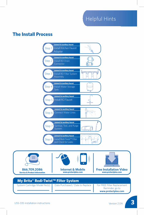
The Install Process
Step 1 Install Kitchen Faucet Adapter
connect to auxiliary faucet
Install RO Drain Connector
connect to auxiliary faucet
Step 2
Install RO Filter System Assembly
connect to auxiliary faucet
Step 3
Install Water Storage Tank
connect to auxiliary faucet
Step 4
Step 5 Install RO Faucetconnect to auxiliary faucet
Connect Water Linesconnect to auxiliary faucet
Step 6
4
Please wear safety glasses to protect eyes when drilling.
CAUTION!
Operation / Maintenance DataThese units are intended for non-commercial use. They should be used only in ambient air temperature of between 40 degrees F / 4.4 degrees C and 100 degrees F / 37.7 degrees C. Placement of these units in direct sunlight or use of electrical heating equipment on these units must be avoided. Replace filter cartridge when and as directed in the installation / operation instructions included with each cartridge. Replacement filter cartridges are available at retail outlets.
Please read all instructions, specifications, and precautions before installing and using your water filter system.
Because of the product’s limited service life and to prevent costly repairs or possible water damage, we strongly recommend that the head of the filter be replaced every five years. If the head of the filter has been in use for longer than this period, it should be replaced immediately. Date the top of any new head to indicate the next recommended replacement date.
DO NOT DRILL THROUGH AN ALL-PORCELAIN OR CAST IRON SINK. If installing on an all-porcelain or cast iron sink, the faucet must be mounted in a pre-drilled sprayer hole or through the countertop next to the sink. If the countertop must be drilled, make certain that the area below the drilling location is free of wiring and pipes. Also, make sure that there is sufficient room to make the proper connections to the bottom of the faucet mount. DO NOT DRILL THROUGH COUNTER TOPS MORE THAN 1” IN THICKNESS OR COUNTERTOPS MADE OF TILE, MARBLE, GRANITE, OR SIMILAR SUBSTANCE. Consult with a plumber or the countertop manufacturer for assistance.
NOTICE
This filter must be protected from freezing, which can cause cracking of the filter and water leakage.
Precautions: for cold water use only.
Consult your local plumbing codes and install accordingly.
WARNING: Be sure that all electrical appliances and outlets are turned off at the circuit breaker before working in the cabinet area.
WARNING
• These filters are not water purifiers. Do not use with water that is microbiologically unsafe or of unknown quality without adequate disinfection before or after the system. Systems certified for Cyst reduction may be used on disinfected water that may contain filterable Cysts.
• This system is not intended to convert waste water or raw sewage into drinking water.
• This unit is not designed to filter sulfur odor (rotten egg odor) caused by hydrogen sulfide. Use of carbon filters to treat sulfur odor may intensify taste/odor problems.
• Please comply with all state and local regulations regarding the installation of water treatment devices.
• The contaminants or other substances reduced by the water filter device are not necessarily in your water.
Filtration Facts!
Before You Begin
5Version 2.0AUSS-335 installation instructions
HOT COLD
Packaged ItemsShown in White
Storage Tank
1/4” line to Tank
1/4” line to Faucet
3/8” line to Drain
1/4” line to Air Gap1/4” line to Filter
Drain Adapter
KitchenFaucet Adapter
1/4" white tubing to filter1/4" red tubing to membrane drain
3/8" red tubing to drain
3/8" white tubing to faucet
3/8" white tubing to tankDrain
Connector
Plan Your Installation: It is recommended to read through the entire manual before beginning your installation. Follow all steps exactly. Reading this manual will also help you get all the benefits from your system. Your Reverse Osmosis Drinking Water System can be installed under a sink or in a remote location. Typical remote sites are a basement, laundry room, or utility room. Review the location options below and determine where you are going to install your system.
Under the Sink Location: The Reverse Osmosis Filter Assembly and storage tank are normally installed in a kitchen or bathroom sink cabinet. See top diagram. A suitable drain point is needed for reject water from the Reverse Osmosis Filter.
Remote Location: You can also locate the Reverse Osmosis Filter Assembly and storage tank in a remote location away from the Reverse Osmosis Faucet. You will need a nearby water source and drain point. See bottom diagram. Note: Ensure the location is heated. Cold incoming water will adversely affect RO flow rate.
Check Space Requirements: Check size and position of items for proper installation into location chosen. Before starting, close the cold water shut-off valves. Temporarily place tank and filter assembly into cabinet. Double check position of items and space required for proper installation. Remove tank and filter from cabinet and set aside. Note: You must check and comply with all local plumbing codes.
NOTE: DO NOT CONNECT 3/8" RED DRAIN TUBING TO DRAIN WITH A GARBAGE DISPOSAL.
Plan Your Installation
66
Introduction
Thank you for your recent purchase of the Brita® Reverse Osmosis (RO) Filtration System. You have purchased a filtration system with a technology that has proven itself effective for filtering ultra-fine water contaminants. This method of filtration is the most common water treatment technology used by premium bottled water companies.
The system uses pressure and a membrane with very fine pores wrapped around a core. Pressure is used to force water through many layers of the membrane. Because of this small pore size and the many layers of the membrane the water has to travel through, this RO system is capable of reducing many kinds of contaminants that many traditional carbon block filters are unable to reduce. Contaminants like Chromium (VI), Arsenic (V), and Nitrites/Nitrates. For a complete listing of all contaminants this sytem removes, please refer to the Performance Data Sheet included with this sytem.
This system is rated to produce around 19 gallons per day of filtered water. That is why there is a pressurized water tank that comes with this sytem. The system is always working to produce filtered water to keep the storage tank filled with filtered water. The system also comes with two carbon block filters to help improve the taste of water as well.
The system, once properly installed, is fully automatic. It continues to filter water until the tank is full. As the tank is drained from use, it again starts to filter water to fill the tank. There is also another automatic function of this filter - a back-flush. The membrane uses a cross flow to sweep away rejected contaminants from the water left behind in the membrane. These contaminants are flushed down the drain through the drain adapter. You will sometimes hear a gurgling sound coming from the faucet - this is to let you know the RO is flushing the membrane. All of this of course helps to optimize the life of the membrane. The 12 month filter life would be considerably less without this feature.
All of this works off the natural pressure supplied by your home's household water lines. Pressure should be between 40 PSI and 100 PSI (maximum). This system is complex. Be sure to read the set-up instructions and perform all maintenance procedures to enjoy RO filtered water from your system.
If you would like to learn more about Reverse Osmosis, please visit our website or scan the MS Tag at the bottom of this page. And remember, our experienced Customer Service team is available to answer any questions you may have.
Thank you and enjoy!Sincerely,Brita and Protect Plus Water Filtration Team
7Version 2.0AUSS-335 installation instructions
• Locate cold water line in sink cabinet. Turn off the cold water supply to sink.
• Turn on kitchen faucet to allow water to completely drain from line.
• Disconnect cold water line from 1/2" threaded stem on bottom of kitchen faucet.
• Holding Kitchen Faucet Adapter in an upright position (see diagram), screw onto threaded faucet stem.
• Connect the cold water supply line to the Kitchen Faucet Adapter. Firmly tighten the nut.
Note: If rigid plumbing pipe (metal or plastic) is used, you may need to shorten supply pipe using a hacksaw or pipe cutter to accomodate the Kitchen Faucet Adapter.
materials and tools needed
CAUTION
safety glasses
Step 1 Install Kitchen Faucet Adapter
connect to auxiliary faucet
COLD WATER VALVE
WARNING
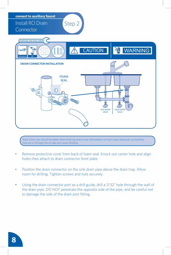
• Remove protective cover from back of foam seal. Knock out center hole and align holes then attach to drain connector front plate.
• Position the drain connector on the sink drain pipe above the drain trap. Allow room for drilling. Tighten screws and nuts securely.
• Using the drain connector port as a drill guide, drill a 7/32" hole through the wall of the drain pipe. DO NOT penetrate the opposite side of the pipe, and be careful not to damage the side of the drain port fitting.
Note: Extra care should be taken when entering drains near dishwashers or food waste disposals, as backflow may occur through the air gap and cause flooding.
materials and tools needed
safety glasses drill
DRAIN CONNECTOR INSTALLATION
Step 2Install RO Drain Connector
connect to auxiliary faucet
8
WARNINGCAUTION
FOAM SEAL
9Version 2.0AUSS-335 installation instructions
• Choose an easy-to-access area under the sink to mount RO System Head.
• Mark holes for mounting screws on the wall surface using the built-in bracket on back of the RO System Head as a guide.
• Drill two pilot holes for the mounting screws. Insert mounting screws into the wall with a phillips screwdriver, leaving approximately 3/8" of each mounting screw exposed.
• Hang the RO System Head on the mounting screws.
Note: To allow adequate space for filter changes, allow a minimum clearance of 4" to 6" below the filter to the floor. The filter System Assembly must be mounted in a vertical position.
Note: Mount Filter System Head to a solid cabinet wall or wall. If a solid surface is not available, use hollow-wall anchor bolts or toggle bolts (not included) to secure to the wall.
Mount the Reverse Osmosis Filter System Assembly Head using the two mounting screws. The mounting screws allow you to lift the RO Filter System Assembly without any hardware removal.
Step 3 Install RO Filter System Assembly
connect to auxiliary faucet
materials and tools needed
WARNING
4-6" FROM BOTTOM
Mount to cabinet in
vertical position
safety glasses drill phillipsscrewdriver
10
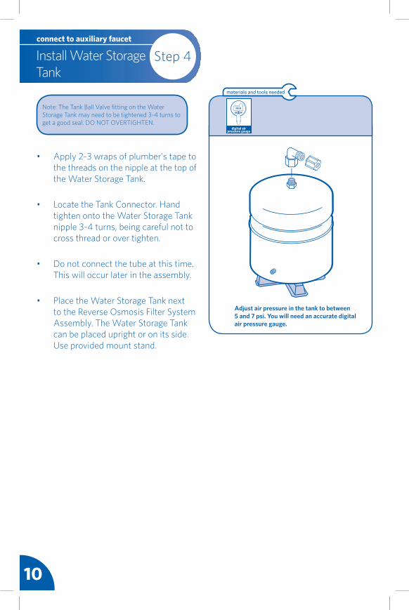
Step 4Install Water Storage Tank
connect to auxiliary faucet
Adjust air pressure in the tank to between 5 and 7 psi. You will need an accurate digital air pressure gauge.
• Apply 2-3 wraps of plumber's tape to the threads on the nipple at the top of the Water Storage Tank.
• Locate the Tank Connector. Hand tighten onto the Water Storage Tank nipple 3-4 turns, being careful not to cross thread or over tighten.
• Do not connect the tube at this time. This will occur later in the assembly.
• Place the Water Storage Tank next to the Reverse Osmosis Filter System Assembly. The Water Storage Tank can be placed upright or on its side. Use provided mount stand.
materials and tools needed
Note: The Tank Ball Valve fitting on the Water Storage Tank may need to be tightened 3-4 turns to get a good seal. DO NOT OVERTIGHTEN.
10
000.00
digital air pressure gauge
11Version 2.0AUSS-335 installation instructions
DO NOT DRILL THROUGH AN ALL-PORCELAIN OR CAST IRON SINK. If installing on an all-porcelain or cast iron sink, the faucet must be mounted in a pre-drilled sprayer hole or through the countertop next to the sink. If the countertop must be drilled, make certain that the area below the drilling location is free of wiring and pipes. Also, make sure that there is sufficient room to make the proper connections to the bottom of the faucet mount. DO NOT DRILL THROUGH COUNTER TOPS MORE THAN 1” IN THICKNESS OR COUNTERTOPS MADE OF TILE, MARBLE, GRANITE, OR SIMILAR SUBSTANCE. Consult with a plumber or the countertop manufacturer for assistance.
CAUTION!
• Determine where you are going to install your RO Faucet Body.
• Check to ensure the RO Faucet Body will mount flat against the mounting surface.
• Visually review the routing of the tubes from the RO System Head to the RO Faucet Body. Check to ensure there is adequate tube routing space between the RO Faucet Body and RO System Head.
• If drilling is needed, drill a 1-3/8" diameter hole in the mounting surface.
Step 5 Install RO Faucetconnect to auxiliary faucet
Select Location of Reverse Osmosis Faucet Mounting Hole. You will need to select the location of the Reverse Osmosis Faucet. You have three options to choose from:• Use an existing sink top hole. This
may be blank. This is for the spray hose or soap dispenser (must be between 1-3/8" and 1-5/8" in diameter).
• Drill a new hole in the sink.• Drill a new hole in the countertop
next to the sink.
Step 5 continued on next page >>
safety glasses drill
COLD
1/4” line to Tank
1/4” line to Faucet
3/8” line to Drain
1/4” line to Air Gap1/4” line to Filter
Drain Adapter
E
materials and tools needed
1/4" white tubing to filter
1/4" red tubing to membrane drain
3/8" red tubing to drain
3/8" white tubing to faucet
3/8" white tubing to tankDrain Connector
WARNING
12
<< Step continued from previous page
Step 5Install RO Faucetconnect to auxiliary faucet
• Locate and organize your RO Faucet install parts. See list on page 2.
• Attach 3/8" white tube to RO Faucet Body.
• Route the 3 tubes attached to the RO Faucet Body through the RO Faucet Base, but don't connect the RO Faucet Body to the RO Faucet Base yet. Then route the 3 tubes through the hole in the sink until 12" of tubing remains above the sink. Lay RO Faucet Body on the counter top.
• Push the toggle bolts on the RO Faucet Body through the sink hole until the RO Faucet Body is flat against the sink surface. Position the toggle bolts to catch under the lower surface of the sink or counter. Ensure that they will not obstruct the
materials and tools needed
faucet stem from sitting in place. Tighten the toggle bolts until the RO Faucet Base is mounted loosely to the surface. TIP: Make sure to keep the "wings" of the toggle bolts free to allow all tubing and faucet stem room. Install the faucet base with the bolts at 5 & 11 o'clock positions to have the handle positioned at 90 degrees to the right.
• Firmly mount the RO Faucet Body to the RO Faucet Base by turning 1/4 clockwise to lock. Ensure the RO Faucet Body Handle is positioned to your liking. TIP: If there is not enough clearance for the tubing and stem, the toggle wings may need to be adjusted to create more clearance.
• Turn the RO Faucet Body 1/4 turn counter-clockwise and remove the faucet enough to tighten the RO Faucet Base toggle bolt screws firmly. DO NOT OVER-TIGHTEN.
• Mount the RO Faucet Body to the RO Faucet Base and turn 1/4 turn clockwise until it locks.
• Mount the RO Faucet Spout to the RO Faucet Body by screwing spout nut to body.
mounting surface
hole
3/8" red tube
3/8" white tube
1/4" red tube
WARNING
13Version 2.0AUSS-335 installation instructions
Step 6 Connect Water Linesconnect to auxiliary faucet
• Determine lengths of 1/4" plastic tubing needed to connect to both inlet port to Auxiliary Faucet Adapter and outlet port to Auxiliary Faucet.
• Cut 1/4" plastic tubing squarely on both ends to length.
• Avoid extra long lengths that may create kinks in the line.
• Insert all tubing into push-to-fit connectors as illustrated.
materials and tools needed
CAUTION
safety glasses
Install 1/4" Plastic Tubing for Water Supply Line from Kitchen Faucet Adapter to System Head Inlet
• Determine lengths of 1/4" plastic tubing needed to connect to both inlet port to Auxiliary Faucet Adapter and outlet port to Auxiliary Faucet.
• Cut 1/4" plastic tubing squarely on both ends to length.
• Avoid extra long lengths that may create kinks in the line.
• Insert all tubing into push-to-fit connectors as illustrated.
Install 3/8" Plastic Tubing for Water Supply Line from System Head Outlet to RO Faucet
INLET
FAUCET TANK
WARNING
Step 6 continued on next page >>
14
Step 6Connect Water Linesconnect to auxiliary faucet
Air Gap from Faucet to RO Assembly
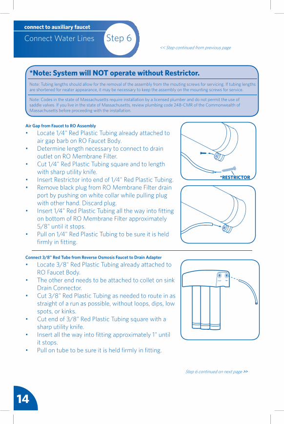
• Locate 1/4" Red Plastic Tubing already attached to air gap barb on RO Faucet Body.• Determine length necessary to connect to drain outlet on RO Membrane Filter.• Cut 1/4" Red Plastic Tubing square and to length with sharp utility knife.• Insert Restrictor into end of 1/4" Red Plastic Tubing.• Remove black plug from RO Membrane Filter drain port by pushing on white collar while pulling plug with other hand. Discard plug.• Insert 1/4" Red Plastic Tubing all the way into fitting on bottom of RO Membrane Filter approximately 5/8" until it stops.• Pull on 1/4" Red Plastic Tubing to be sure it is held firmly in fitting.
Note: Tubing lengths should allow for the removal of the assembly from the mouting screws for servicing. If tubing lengths are shortened for neater appearance, it may be necessary to keep the assembly on the mounting screws for service.
Note: Codes in the state of Massachusetts require installation by a licensed plumber and do not permit the use of saddle valves. If you live in the state of Massachusetts, review plumbing code 248-CMR of the Commonwealth of Massachusetts before proceeding with the installation.
*Note: System will NOT operate without Restrictor.
*RESTRICTOR
Connect 3/8" Red Tube from Reverse Osmosis Faucet to Drain Adapter
• Locate 3/8" Red Plastic Tubing already attached to RO Faucet Body.• The other end needs to be attached to collet on sink Drain Connector.• Cut 3/8" Red Plastic Tubing as needed to route in as straight of a run as possible, without loops, dips, low spots, or kinks.• Cut end of 3/8" Red Plastic Tubing square with a sharp utility knife.• Insert all the way into fitting approximately 1" until it stops.• Pull on tube to be sure it is held firmly in fitting.
FAUCET TANK
Step 6 continued on next page >>
<< Step continued from previous page
15Version 2.0AUSS-335 installation instructions
materials and tools needed
utility knife
<< Step continued from previous page
Step 6 Connect Water Linesconnect to auxiliary faucet
Connect Tubing from RO System Head to Water Storage Tank
• Use remaining 3/8" White Tubing and determine length necessary to connect Tank outlet (labeled "TANK") on RO System Head to Water Storage Tank.• Cut 3/8" White Plastic Tubing square with a sharp utility knife.• Wet end of tubing and insert into compression nut of Tank Connector fitting (which was connected to tank previously).• Tighten compression nut to secure tubing to Tank Connector.• Insert other end of 3/8" White Plastic Tubing into outlet of RO System Head (labeled "TANK") approximately 5/8" until it stops.
HOT COLD
Packaged ItemsShown in White
Storage Tank
1/4” line to Tank
1/4” line to Faucet
3/8” line to Drain
1/4” line to Air Gap1/4” line to Filter
Drain Adapter
KitchenFaucet Adapter
1/4" white tubing to filter1/4" red tubing to membrane drain
3/8" red tubing to drain
3/8" white tubing to faucet
3/8" white tubing to tankDrain
Connector
WARNINGCAUTION
16
• Make sure water supply to RO Filter System Assembly is off.
• Open the RO Faucet. If Water Storage Tank is not already empty, allow the watrer to completely empty.
• Find eyedropper included in package and common household bleach (5.25%).
• Disconnect 3/8" White Plastic Tubing from Water Storage Tank by unscrewing nut from Tank Connector fitting.
• Add 3 ml. of bleach into open end of Water Storage Tank 3/8" White Plastic Tubing. Handle bleach according to manufacturer's instructions.
• Reconnect Water Storage Tank and 3/8" White Plastic Tubing to Tank Connector fitting.
• Sanitizing RO Filter System Assembly will be completed during pressure test and purging following steps on Page 17.
materials and tools needed
Sanitizing is recommended immediately after installation of the RO Filter System Assembly. It's also recommended after servicing inner parts. It is important that the person installing or servicing the system have clean hands while handling inner parts of the system. Complete the following steps to sanitize the system.
Sanitize the System
Note: The bleach must be completely removed from system before drinking RO water. See purging instructions below.
Step 7 continued on next page >>
Step 7Sanitize, Test and Purge System
connect to auxiliary faucet
WARNING
17Version 2.0AUSS-335 installation instructions
Step 7 Sanitize, Test and Purge System
connect to auxiliary faucet
<< Step continued from previous page
Pressure Test the System (IMPORTANT: Complete sanitizing procedures on Page 16 before pressure testing.)
• Open cold water supply valve to RO Filter System Assembly.
• Open kitchen faucet. This will purge air from plumbing system. Close kitchen faucet when water runs smooth.
• Ensure RO Faucet is closed.
• Pressure will start to build in RO Filter System Assembly in about 2 hours. Carefully inspect all fittings and connections while the RO Filter System Assembly builds pressure. Check for leaks and fix if any are found by ensuring all tubing is cut square and fully iserted. Also ensure tubing doesn't have a scratch, dent, or notch at the end. If so, cut 1" off squarely and re-insert. If problems exist, refer to the troubleshooting chart or call the toll free number.
Note: When RO Filter System Assembly is first pressurized, water may "discharge" from faucet air gap hole until air is passed from RO Filter System Assembly.
Purge the System
• Open the RO Faucet and let water flow through the system for a 24 hour period. Water will flow heavily until tank becomes empty, and then it will be a slow drip for the balance of 24 hours.
• Close RO Faucet after 24 hour purge is complete.
• Your Reverse Osmosis system is ready for use when purge is complete.
Note: Flow rate will be very slow during the purge.
Review the following operating features before using your Reverse Osmosis System:
You will not have filtered water immediately. It will take 1-3 hours to completely fill the storage tank to create liberal flow from the faucet. The flow rate from the RO system will be less than your kitchen faucet. Water will run to the drain while the RO is filtering water, even when you are not using it. You may hear water going to the drain - this is normal. Water going to the drain will automatically stop when the storage tank is at capacity.
18
Install Redi-Twist™ Filters and Test for Leaks
Step 8connect to auxiliary faucet
LOCK
LOCK
1/4 turn
Align ArrowLOCK
* Membrane filter cartridge ALWAYS in this position
1st S
tage
Carb
on F
ilter
2nd
Stag
eM
embr
ane
Filte
r
3rd
Stag
eCa
rbon
Filt
er
LOCK
LOCK
LOCK
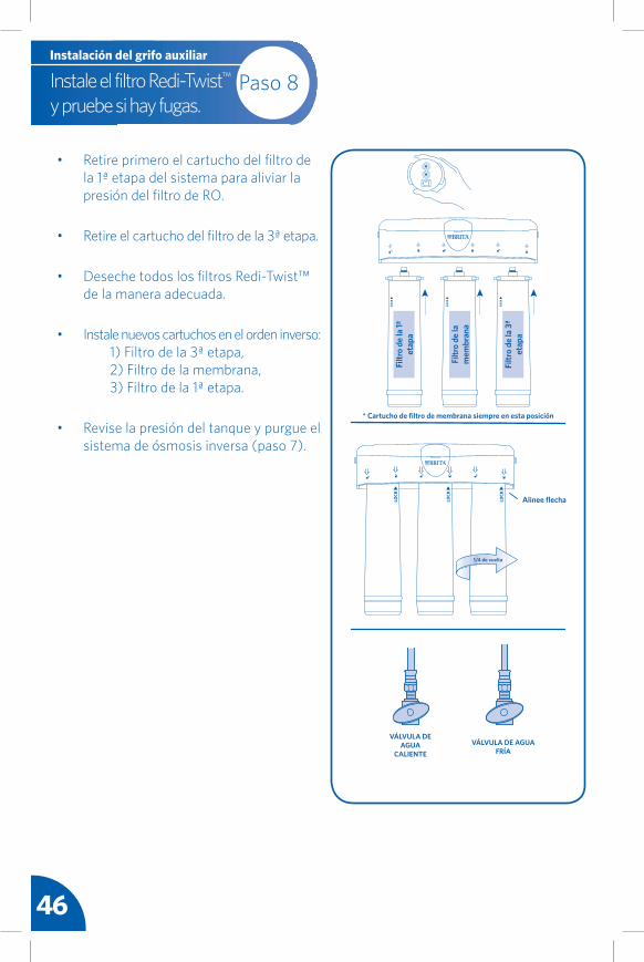
• Remove the 1st Stage filter cartridge first from the system to relieve pressure on the RO filter.
• Remove the 3rd Stage filter cartridge.
• Discard all of the Redi-Twist™ filters in a proper manner.
• Install new filters in reverse order: 1) 3rd Stage filter, 2) Membrane filter, 3) 1st Stage filter.
• Check tank pressure, and purge the Reverse Osmosis System (Step 7).
19Version 2.0AUSS-335 installation instructions
Filter Replacement(every 12 months)
connect to auxiliary faucet
RE
PLACE EVERY
TWELVE MONTH
S
For FREE Filter Replacement Reminder, go to www.protectplus.com
Note: Place paper towels or rag under the filter system to catch any water drips.
Note: The 1/4" plastic tubing does not need to be disconnected for general routine maintenance and filter replacement. However, plastic tubing may be easily disconnected. Simply turn off the water supply to the filter system. Press in the gray collar around the fitting while pulling the plastic tubing out with the other hand.
LOCK
1/4 turn
LOCK
1st S
tage
Carb
on F
ilter
3rd
Stag
eCa
rbon
Filt
er
LOCK
LOCK
Filter Replacement(every 6 months)
connect to auxiliary faucet
RE
PLACE EVERY
SIX M ONTHS
LOCK
1/4 turn
2nd
Stag
eM
embr
ane
Filte
r
• Remove the Redi-Twist™ pre-filter cartridge from the system by turning it to the left.
• Remove the Redi-Twist™ post-filter cartridge from the system by turning it to the left.
• Discard the Redi-Twist™ filters in a proper manner.
• Install new Redi-Twist™ filters in reverse order: 1) 3rd Stage filter, 2) Membrane filter, 2) 1st Stage filter.
• Purge the RO System per the instructions in Step 7.
1st Stage and 3 Stage Filter Replacement: Membrane Filter Replacement:
20
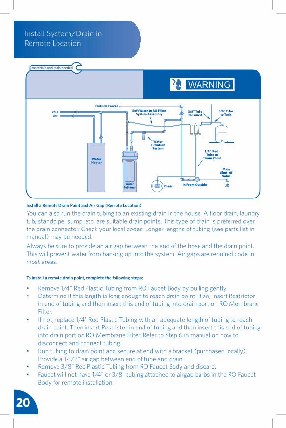
You can also run the drain tubing to an existing drain in the house. A floor drain, laundry tub, standpipe, sump, etc. are suitable drain points. This type of drain is preferred over the drain connector. Check your local codes. Longer lengths of tubing (see parts list in manual) may be needed.Always be sure to provide an air gap between the end of the hose and the drain point. This will prevent water from backing up into the system. Air gaps are required code in most areas.
materials and tools needed
WARNING
Install a Remote Drain Point and Air Gap (Remote Location)
Install System/Drain in Remote Location
• Remove 1/4" Red Plastic Tubing from RO Faucet Body by pulling gently.• Determine if this length is long enough to reach drain point. If so, insert Restrictor in end of tubing and then insert this end of tubing into drain port on RO Membrane Filter.• If not, replace 1/4" Red Plastic Tubing with an adequate length of tubing to reach drain point. Then insert Restrictor in end of tubing and then insert this end of tubing into drain port on RO Membrane Filter. Refer to Step 6 in manual on how to disconnect and connect tubing.• Run tubing to drain point and secure at end with a bracket (purchased locally). Provide a 1-1/2" air gap between end of tube and drain.• Remove 3/8" Red Plastic Tubing from RO Faucet Body and discard.• Faucet will not have 1/4" or 3/8" tubing attached to airgap barbs in the RO Faucet Body for remote installation.
To install a remote drain point, complete the following steps:
21Version 2.0AUSS-335 installation instructions
SPECIFICATIONS - QUALIFIED SYSTEM PERFORMANCE
1 Industry standards measure RO Membranes performance with no back pressure on the product water, at 60 psig (414kPa) and 77°F (25°C). Further conditions on the above are 250 ppm TDS and a 30.6% recovery rate. Production rate and TDS reduction figures are for a new Membrane that has been rinsed for 24 hours. The production rate of a new Membrane can decrease by 10% per year or more, depending upon the scaling and fouling tendencies of the Feed Water.2 Measured at 50 psi, 77° ± 2°F, and 717 mg/l TDS per NSF/ANSI Standard 58.
3 Efficiency rating means the percentage of the influent water to the system that is available to the user as reverse osmosis treated water. Under operating conditions that approximate daily usage.4 Recovery rating means the percentage of the influent water to the membrane portion of the system that is available to the user as reverse osmosis treated water when the system is operated without a storage tank or when the storage tank is bypassed.
Non-potable Water Sources: Do not attempt to use this product to make safe drinking water from non-potable water sources. Do not use the system on microbiologically unsafe water, or water of unknown quality without adequate disinfection before or after the system. This system is certified for cyst reduction and may be used on disinfected water that may contain filterable cysts.
Arsenic Reduction: This system shall only be used for arsenic reduction on chlorinated water supplies containing detectable residual free chlorine at the system inlet. Water systems using an inline chlorinator should provide a one minute chlorine contact time before the reverse osmosis system.
Nitrate/Nitrite Test Kit: This system is acceptable for treatment of influent concentrations of no more than 27 mg/L nitrate and 3 mg/L nitrite in combination measured as N. It is certified for nitrate/nitrite reduction only for water supplies with a pressure of 280 kPa (40psig) or greater. This sytem is supplied with a nitrate/nitrite test kit. Product water should be monitored periodically according to the instructions provided with the test kit.
Installations in The Commonwealth of Massachusetts: The Commonwealth of Massachusetts requires installation be performed by a licensed plumber and do not permit the use of saddle valves. Plumbing code 248-CMR of the Commonwealth of Massachusetts must be followed in these cases.
Product Water Testing: The Reverse Osmosis System contains a replaceable membrane cartridge critical for the effective reduction of total dissolved solids (TDS).
Replacement of the reverse osmosis membrane cartridge: The reverse osmosis system contains a replaceable membrane cartridge critical to the efficiency of the system.This membrane should be replaced every 12 months, or more often based on your local water. Only replace the reverse osmosis membrane with a part approved for use in your DuPont Reverse Osmosis system.
Specifications
Membrane Production1
Membrane TDS Reduction1
System Production2
TDS Reduction2
Maximum TDSMaximum Water Hardness @ 6.9pHMaximum Chlorine in WaterSupply Water pH LimitsDrain (reject water) FlowEmpty Storage Tank PrechargeStorage Tank Capacity2
Supply Water Pressure LimitsSupply Water Temperature LimitEfficiency3
The pre-filter and post-filters are replaceable activated carbon cartridges, Brita™ Redi-Twist™ USF-201. They are located in the 1st and 3rd positions of the 3-stage system. It is recommended to replace the pre-filter and post-filter cartridges at least every 6 months of product water use. The pre-filter and post-filter ARE BOTH Brita™ Redi-Twist™ USF-201 cartridges. You may need to replace these filters more often with a great deal of use or a high level of incoming sediment. This will protect the RO membrane from being destroyed by chlorine and plugging with sediments. You may notice a slower output of product water as the pre-filter and post-filters build up with sediments. Replace the pre-filter and post-filter cartridges when this occurs. See below for instructions.
RO Membrane Cartridge MaintenanceThe Reverse Osmosis cartridge (Brita™ Redi-Twist™ USF-205) is a tightly wound membrane located in the center position of the 3-stage system. The membrane reduces the dissolved solids and organic matter. The life of the Reverse Osmosis membrane cartridge depends on the pH and hardness of the supply water (see specifications). Membrane life is shorter with higher pH. For example, if supply water pH is under 7.5, the cartridge may last up to 12 months. However, cartridge life may be as short as 6 months if the pH is higher than 8.0. Higher pH weakens the cartridge membrane and causes pin-hole leaks. It's time to replace the Reverse Osmosis cartridge when the production rate and quality of the output water drops. The output water may begin to taste different, indicating solids and organics are passing through the RO membrane. See Reverse Osmosis cartridge replacement.
The Reverse Osmosis cartridge output and flow rate is generally determined by three factors: 1. Temperature of incoming water. The lower the temperature is directly proportional to the slower flow rate. All Reverse Osmosis membranes are tested at 77° Fahrenheit. However, incoming water should not exceed 100° Fahrenheit. You need to ensure that the Reverse Osmosis system is placed in a climate controlled area and does not have the potential to freeze. 2. TDS (total dissolved solids) present in the incoming water. More TDS requires more time for the membrane to filter and remove. Ensure incoming TDS does not exceed 2000 ppm. 3. Incoming water puressure is one of the key factors determining the flow rate of the RO membrane. Higher pressure will enable a higher flow rate. Pressure must be above 40 PSI for proper operation. You may need to install a Booster Pump or Permeate Pump if your pressure is below 40 PSI.
Drain Flow Restrictor:The drain flow restrictor is vital for proper operation of the RO membrane cartridge. The restrictor keeps water flowing through the membrane at the proper rate. This is to ensure the system produces the best quality water. Periodically check the restrictor assembly to be sure it is clean and unrestricted. If the drain flow assembly requires service, review Step 6. Disassemble and assemble as shown.
Check Valve: The check valve is vital for proper operation of the Reverse Osmosis system. The check valve ensures that the product water is flowing in the proper direction, and does not allow it to flow backwards. If the check valve requires service, disassemble by removing the (5) screws and assemble as shown.Automatic Shut-Off: The automatic shut-off conserves water when the storage tank is full by turning the system off until more product water is needed. If the automatic shut-off requires service, disassemble by removing the (5) screws and assemble as shown.Change Quick Connect Collet and O-Ring:1. Remove the collet and o-ring from the fitting with a small screwdriver. Be careful not to scratch the internal walls of the collet port.2. Clean collet port, lubricate and insert the o-ring seal into the bottom of the port.3. Push the collet inward until it locks in place.
Prefilter/PostfilterMaintenance
connect to auxiliary faucet
23Version 2.0AUSS-335 installation instructions
Low Water Quantity
TroubleshootingGuide
connect to auxiliary faucet
POSSIBLE CAUSE SOLUTION
Incoming water temperature is cold.
Incoming water has extremely high level of Total Dissolved Solids (TDS).
Low incoming water pressure.
Feed water valve is plugged or closed.Carbon pre-filter is clogged.Reverse Osmosis Membrane is fouled.
Air pressure in holding tank is incorrect.
Air bladder in holding tank is ruptured.No water to drain. Drain flow restrictor is clogged.No water to drain. Air gap faucet is clogged.
Check valve on RO Membrane Housing is stuck.The automatic shut-off valve is malfunctioning.
The water temperature is one of the key factors in the performance of the RO membrane. The higher the temperature, the higher the flow rate, and vice versa. All RO Membrane elements are tested and rated at 77° Fahrenheit. Ensure the RO is installed in a heated area of the home.Incoming TDS Level is one of the key factors determining the flow rate of the RO membrane. More TDS requires more time for the membrane to remove - no solution is required. Ensure incoming TDS does not exceed 2000 ppm.Incoming water pressure is one of the key factors determining the flow rate of the RO membrane. Higher pressure will enable a higher flow rate. Pressure must be above 40 PSI for proper operation. You may need to install a Booster Pump or Permeate Pump if your pressure is below 40 PSI.Open valve or unclog.Replace filter with Brita model number USF-201.Make sure incoming water pressure is within operating limits. Make sure drain line is not clogged. Correct cause of fouling or replace RO membrane.Empty water from holding tank. Air pressure in valve stem should be between 5-7 PSI. Increase PSI similar to adding air to bicycle tire.Replace holding tank. Call Customer Service for replacement.Remove tubing from membrane drain port, cut 1" length off end of tubing and add new restrictor.
Remove faucet body from faucet base and disconnect drain 3/8" tubing. Ensure the drain connector is properly aligned with the hole in the drain pipe. Ensure there are no obstructions - clear them out. Remove faucet body from faucet base and disconnect air gap 1/4" tubing. Ensure there are no obstructions - clear them out. Replace Air Gap Faucet.Replace whole check valve assembly. Refer to maintenance section.
Replace automatic shut-off valve. Refer to maintenance section.
Air pressure in holding tank is incorrect. (THIS IS THE #1 REASON FOR LOW FLOW FROM REVERSE OSMOSIS FAUCET)
Carbon post-filter is clogged.
Heavy water use. Holding tank is empty.
Low Water Production.
Open faucet and empty water from holding tank. Shut off feed water to system and remove holding tank from under sink (the tak is easier to work on). Locate the air valve stem (just like on a car or bicycle tire) and add air. If there is still water in the tank, continue to add air until all the water is removed. Once all the water is removed, continue to add air and pressurize to 5-7 psi. Reinstall the tank under the sink, turn on the feed supply to the system and allow the tank to fill.
Replace post-filter with Brita™ Redi-Twist™ USF-201.
Allow holding tank to refill.
See previous section on Low Quantity of Water from Holding Tank.
POSSIBLE CAUSE SOLUTION
Low Water Pressure from Dispensing Faucet
24
TroubleshootingGuide
connect to auxiliary faucet
POSSIBLE CAUSE SOLUTION
Clogged pre-filter.Low incoming water pressure.Reverse Osmosis membrane is expended.
Product water and drain water lines are reversed.No water to drain. Drain flow restrictor is clogged.No water to drain. Air gap faucet is clogged.
The automatic shut-off valve is not closing.New carbon post-filter has not been rinsed completely.The incoming feed water TDS has increased.
Replace pre-filter with Brita™ Redi-Twist™ USF-201.Incoming water pressure must be above 40 psi. Install a Booster Pump or Permeate Pump.If membrane life is unusually short, find and correct the problem (average life is 1-2 years). Replace RO Membrane.Correct plumbing according to installation instructions.
Remove tubing from membrane drain port, cut 1" length off end of tubing and add new restrictor.
Remove faucet body from faucet base and disconnect air gap 1/4" tubing. Ensure there are no obstructions - clear them out. Replace air gap faucet. Remove faucet body from faucet base and disconnect drain 3/8" tubing. Ensure the drain connector is properly aligned with the hole in the drain pipe. Ensure there are no obstructions - clear them out.Repair or replace automatic shut-off valve. Refer to maintenance section.
Drain holding tank twice to rinse new carbon post-filter. TDS.
An increase in feed water TDS will also give an increase in Product Water TDS.
Product Water is High in Total Dissolved Solids (TDS)
POSSIBLE CAUSE SOLUTION
Water leaks from faucet spout.
Leaks from connection to the faucet.
Ensure the faucet spout is projerly seated. Repair or replace the faucet.
Check and fix compression fittings to faucet. Repair or replace the faucet. Turn off the cold water shut-off valve to the Filter System to release pressure in the system. Loosen and remove the compression nut on the faucet for filtered water stem. Check the 1/4" plastic tubing to see if it is cut squarely. Make sure the 3/8" plastic tubing is placed firmly into the end of the faucet stem; retighten the compression nut securely by hand; then tighten 1/2 turn with an adjustable wrench. Make sure tube insert is inside the tubing and the ferrule is in proper orientation. Turn the cold water shut-off valve back on and turn on the faucet for filtered water.
Faucet Connect Fittings Leak
25Version 2.0AUSS-335 installation instructions
POSSIBLE CAUSE SOLUTION
TroubleshootingGuide
connect to auxiliary faucet
LOCK
LOCK
LOCK
Air gap is clogged.
Drain line is clogged.
Drain flow rate is too high.
Remove faucet body from faucet base and disconnect air gap 1/4" tubing. Ensure there are no obstructions - clear them out.Remove faucet body from faucet base and disconnect drain 3/8" tubing. Ensure the drain connector is properly aligned with the hole in the drain pipe. Ensure there are no obstructions - clear them out.Replace flow restrictor.
Tubing is crimped or bent at connection.
Tubing is not cut squarely.
Tubing does not enter fitting at 90° angle - not enough tubing.
O-ring inside fitting is damaged.
Collet inside wall is damaged.
Remove tubing, cut 1" off squarely - making sure to not crimp. Use a very sharp exacto or utility knife. It is not recommended to use side-cutting or diagonal-cutting pliers. Wet the tubing end and insert 5/8" until fully inserted.Remove tubing, cut 1" off squarely - making sure to not crimp. Use a very sharp exacto or utility knife. It is not recommended to use side-cutting or diagonal-cutting pliers. Wet the tubing end and insert 5/8" until fully inserted.Re-route tubing to allow it to enter fitting at a straight 90° angle. If not enough tubing to allow, remove tubing and use a longer piece. Remove by pressing in the white collar while pulling the Plastic Tubing out with your other hand.Replace o-ring by removing collet with smal screwdriver. Be careful not to scratch the internal walls of the collet. Ensure new o-ring is properly lubricated.Replace collet by removing with small screwdriver. Be careful not to damage the o-ring.
POSSIBLE CAUSE SOLUTION
Carbon post-filter is exhausted.There is foreign matter in holding tank.Product water and drain water lines are reversed.Dissolved gases in feed water.Increase in Product Water TDS.
Replace filter with Brita™ Redi-Twist™ USF-201.Follow the clean, flush, and sanitize procedures. Replace all filters.Correct plumbing according to installation instructions.
Pre-treat feed water to remove gasses.See High TDS in Product Water Section.
POSSIBLE CAUSE SOLUTION
Tastes and Odors in Product Water
Leak from Air Gap Hole in Faucet
Quick Connect Fittings Leak
26
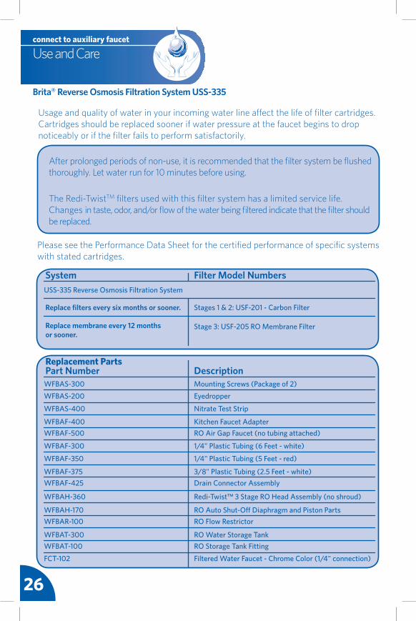
Usage and quality of water in your incoming water line affect the life of filter cartridges. Cartridges should be replaced sooner if water pressure at the faucet begins to drop noticeably or if the filter fails to perform satisfactorily.
After prolonged periods of non-use, it is recommended that the filter system be flushed thoroughly. Let water run for 10 minutes before using.
The Redi-TwistTM filters used with this filter system has a limited service life. Changes in taste, odor, and/or flow of the water being filtered indicate that the filter should be replaced.
Please see the Performance Data Sheet for the certified performance of specific systems with stated cartridges.
System Filter Model NumbersUSS-335 Reverse Osmosis Filtration System
Stages 1 & 2: USF-201 - Carbon Filter
Stage 3: USF-205 RO Membrane Filter
Part Number DescriptionWFBAS-300 Mounting Screws (Package of 2)WFBAS-200 Eyedropper
WFBAH-360 Redi-Twist™ 3 Stage RO Head Assembly (no shroud)
WFBAH-170 RO Auto Shut-Off Diaphragm and Piston PartsWFBAR-100 RO Flow Restrictor
WFBAT-300 RO Water Storage TankWFBAT-100 RO Storage Tank Fitting
FCT-102 Filtered Water Faucet - Chrome Color (1/4" connection)
Replace filters every six months or sooner.
27Version 2.0A
28
Instrucciones de instalación del USS-335
CONNECT TO AUXILIARY FAUCET
NSF/ANSI StandardsSistema probado y certificado por NSF internacional según la norma NSF/ANSI 42 para cloro estético, sabor y olor, y partículas clase III. Sistema probado y certificado por NSF internacional según la norma NSF/ANSI 58 para quistes, plomo, nitritos/nitratos, arsénico pentavalente, cadmio,
selenio, cromo trivalente, y sólidos totales disueltos (TDS). Sistema probado y certificado por NSF internacional según la norma NSF/ANSI 372 para la conformidad y bajo contenido de plomo.Refiérase a la Hoja de datos del rendimiento para la información completa sobre los componentes que disminuye.
Sistema de filtración por ósmosis inversa Redi-Twist Modelo USS-335
Reverse Osmosis Filtration System
Paso 1
Paso 2
Paso 3
Paso 4
Paso 5
Paso 6
Paso 7
CONECTE AL GRIFO AUXILIAR
1/4 turn
LOCK
LOCK
LOCKPaso 8
30
Tornillos de montajeAdaptador de grifo de cocinaTubería blancaTubería rojaBanda para prueba de nitratoGoteroSello de espumaTornillos y tuercas
Cabezal de sistema de filtro con soporte incorporadoFiltro Redi-Twist™: (2) filtro de carbón y (1) membranaEl grifo llave de aguaTanque de almacenaje de aguaConector de drenajeConector del tanqueReductor
Tanque de almacenaje de agua
Tubería blanca (3/8" y 1/4")
Tubería roja (3/8" y 1/4")
Base del grifo
Banda para prueba de nitrato
Conector de drenaje
Gotero
Tapa de compresión (para conector del rociador de manguera del grifo de cocina)Taladro con brocas de 1/4” y 9/16” o 5/8”Pernos de anclaje o pernos acodados para pared huecaSegueta (para los tubos de metal) Cinta de plomería acoples que debe adquirir
Conectador del tanque
Reductor
Sello de espuma Tornillos y tuercas
Sacador de centro
000.00
Casquillo de la compresión Lima
Implementos y materiales necesarios
Componentes principales Componentes secundarios
Contenido del paquete
implementos necesarios para la
instalaciónCabezal del sistema de filtración
1st e
tapa
de
filtr
o de
car
bón
3rd
etap
a de
fil
tro
de c
arbó
n
2nd
etap
a de
fil
tro
de m
embr
ana
Filtro Redi-Twist™ (1st, 2nd, y 3rd etapa)
El grifo llave de agua
Principal:
secundarios: artículos opcionales:
Tornillos de montajeAdaptador de grifo
de cocina
Destornillador Phillips
Broca para tal-adro de 1/8”
Llave ajustable
Cuchilla multiuso
1 2 3
30’
Cinta para medir
Gafas de seguridad
Taladro
31Version 2.0AUSS-335 installation instructions
Desinfecte, pruebe y purgue el sistema
Instalación del grifo auxiliar
Paso 7
1/4 turn
LOCK
LOCK
LOCK
Instale el filtro Redi-Twist™ y pruebe si hay fugas
Instalación del grifo auxiliar
Paso 8
Consejos útiles
El Proceso de Instalación
Paso 1 Instale el adaptador del grifo de cocina
Instalación del grifo auxiliar
Instale el conector de desagüe de ósmosis inversa
Instalación del grifo auxiliar
Paso 2
Instale el ensamble del filtro RO
Instalación del grifo auxiliar
Paso 3
Instale el tanque de almacenaje
Instalación del grifo auxiliar
Paso 4
Paso 5 Instale el grifo llave de agua RO
Instalación del grifo auxiliar
Conecte las tuberías de agua
Instalación del grifo auxiliar
Paso 6
Sistema de filtración My Brita® Redi-Twist™Número de modelo del sistema Fecha de compra / Fecha de cambio Para recordatorios GRATIS de
cambio del filtro, ingrese a www.protectplus.com
Información del producto y servicioVideo de instalación gratuitoInternet y móvil866.709.2086
32
Use gafas de seguridad para proteger los ojos cuando taladre.
PRECAUCIÓN!
Información de funcionamiento/mantenimientoEstas unidades no están destinadas para uso comercial. Deben utilizarse sólo en ambientes donde la temperatura del aire está entre 35 grados F / 2 grados C y 100 grados F / 38 grados C. Debe evitar colocar estas unidades en la luz solar directa o el uso de equipo de calefacción. Cambie el cartucho del filtro como y cuando lo indiquen las instrucciones de instalación/operación que se incluyen con cada cartucho. Los cartuchos de reemplazo del filtro están a disposición en las tiendas al detal.
Lea todas las instrucciones, especificaciones y precauciones antes de instalar o utilizar su sistema de filtración de agua.
Debido a la vida de servicio limitada del producto y para evitar reparaciones costosas o posible daño originado por el agua, recomendamos enfáticamente reemplazar el cabezal del filtro cada diez años. Si el cabezal del filtro ha estado en uso por un período mayor, debe reemplazarse de inmediato. Coloque la fecha en la parte superior de cualquier cabezal nuevo para indicar la próxima fecha de reemplazo recomendada.
NO TALADRE EN UN FREGADERO TOTALMENTE ELABORADO EN PORCELANA O HIERRO FUNDIDO. Si instala en un fregadero totalmente elaborado en porcelana o hierro fundido, el grifo deberá estar montado en un agujero previamente taladrado para el rociador o a través de la encimera al lado del fregadero. Si es necesario taladrar la encimera, compruebe que el área debajo del lugar donde va a taladrar no tenga cableado ni tubos. Asimismo, compruebe que exista suficiente espacio para hacer las conexiones adecuadas a la parte inferior del soporte del fregadero. NO PERFORE ENCIMERAS QUE TENGAN MÁS DE UNA PULGADA (2.5 cm) DE ESPESOR NI LAS DE BALDOSAS, MÁRMOL, GRANITO O MATERIALES SIMILARES. Consulte con un plomero o con el fabricante de la encimera para obtener asistencia.
AVISO
Este filtro deberá estar protegido del congelamiento, lo cual puede ocasionar la rajadura del filtro y goteo de agua.
Precauciones: para uso con agua fría únicamente.
Consulte la normativa local de plomería e instale de acuerdo con ella.
ADVERTENCIA: Verifique que todos los electrodomésticos y los tomacorrientes estén desconectados en el interruptor de circuito principal antes de trabajar en el área del gabinete.
ADVERTENCIA
• Estos filtros no son purificadores de agua. No utilice con agua que sea microbiológicamente insegura o de calidad desconocida sin la adecuada desinfección antes o después del paso por el sistema. Los sistemas certificados para la disminución de quistes pueden ser utilizados en aguas desinfectadas que puedan contener quistes filtrables.
• Este sistema no está diseñado para convertir aguas residuales o aguas negras en agua potable.
• Esta unidad no está diseñada para filtrar el olor a azufre (olor a huevos podridos) que ocasiona el sulfuro de hidrógeno. Utilizar filtros de carbón para tratar el olor a azufre puede intensificar los problemas de sabor/olor.
• Cumpla con todas las regulaciones estatales y locales relacionadas con la instalación de las unidades para tratamiento de agua.
• Los contaminantes u otras sustancias que disminuye esta unidad de filtración de agua no están necesariamente en el agua de su vivienda.
Datos sobre la filtración!
Antes de comenzar
33Version 2.0AUSS-335 installation instructions
HOT COLD
Packaged ItemsShown in White
Storage Tank
1/4” line to Tank
1/4” line to Faucet
3/8” line to Drain
1/4” line to Air Gap1/4” line to Filter
Drain Adapter
KitchenFaucet Adapter
1/4" white tubing to filter1/4" red tubing to membrane drain
3/8" red tubing to drain
3/8" white tubing to faucet
3/8" white tubing to tankDrain
Connector
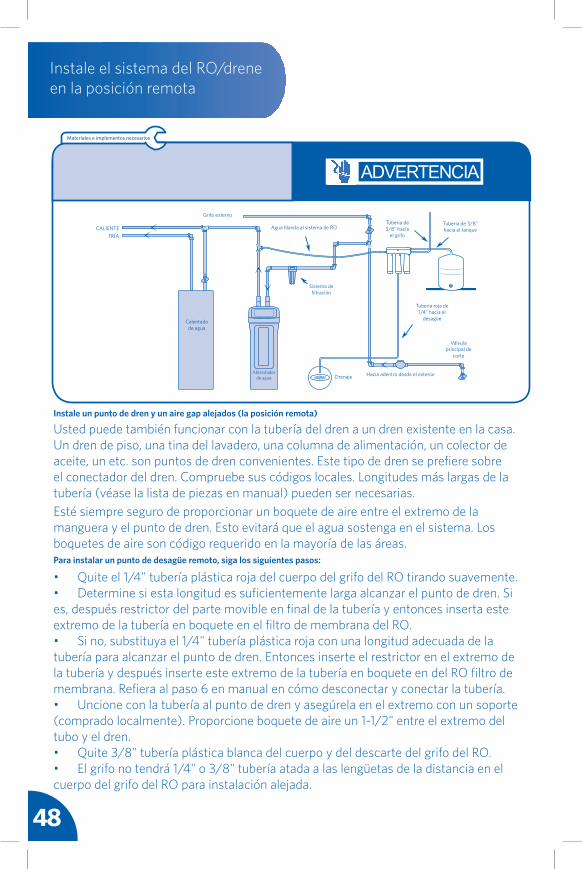
Planifique su instalación: Se recomienda que lea completament el manual antes de comenzar la instalación. Siga todos los pasos exactamente. Leer este manual también contribuirá a brindarle todos los beneficios que ofrece el sistema. Su sistema de agua potable por ósmosis inversa puede instalarse debajo de un fregadero o en una ubicación a distancia. Los lugares comunes a distancia son un sótano, un lavadero o una habitación multiuso. Revise las opciones de ubicación que se indican y determine donde va a instalar su sistema.
Ubicación debajo del fregadero: El ensamble de filtro de ósmosis inversa y el tanque de almacenaje están normalmente instalados en un gabinete de la cocina o el baño. Consulte la parte superior del diagrama. Es necesario establecer un punto adecuando para el drenaje del agua que desecha el filtro de ósmosis inversa.
Ubicación a distancia: También puede ubicar el ensamble del filtro por ósmosis inversa y el tanque de almacenaje en un lugar a distancia del grifo de ósmosis inversa. Necesitará disponer de suministro de agua y punto de drenaje. Consulte la parte inferior del diagrama. Nota: Cerciórese de que la ubicación disponga de calefacción. El agua fría entrante afectará negativamente el índice de flujo RO.
Verifique los requisitos relacionados con el espacio: Revise el tamaño y la posición de los artículos para la instalación adecuada en el ubicación elegida. Antes de comenzar, cierre las válvulas de corte de agua fría. Coloque temporalmente el tanque y el ensamble del filtro en el gabinete. Vuelva a revisar la posición de los elementos y el espacio necesario para una instalación adecuada. Retire el tanque y el filtro del gabinete y déjelos aparte. Nota: Deberá verificar y cumplir con toda la normativa local sobre plomería.
Planifique su instalación
NOTA: No conecte la tubería de drenaje roja de 3/8" a un triturador de desperdicios.
CALIENTE FRÍA
Adaptador de grifo de cocina
Tubería de roja 3/8" hacia el desague
Conector de drenaje
Tubería de blanca 1/4" hacia el filtroTubería de roja de 1/4" hacia el espacio vacio
Tubería de blanca 3/8" hacia el grifo
Tubería de blanca 3/8" hacia el tanque
Tanque de almacenaje de agua
CALIENTEFRÍA
Grifo externo
Calentado de agua
Ablandador de agua
Agua blanda al sistema de RO
Sistema de filtración
Drenaje Hacia adentro desde el exterior
Tuberia roja de 1/4" hacia el
desagüe
Válvula principal de
corte
Tuberia de 3/8" hacia el tanque
Tuberia de 3/8" hacia
el grifo
Los artículos del paquete se ilustran
en blanco
3434
Introducción
Gracias por su reciente compra del sistema de filtración por ósmosis inversa (RO) Brita®. Usted ha adquirido un sistema de filtración con una tecnología cuya efectividad ha sido probada para la filtración de contaminantes extremadamente finos presentes en el agua. Este método de filtración es la tecnología de tratamiento de agua más común que utilizan las empresas de agua embotellada de primera.
El sistema utiliza la presión y una membrana con poros muy finos enrollada alrededor de un núcleo. Se utiliza la presión para forzar el agua a través de muchas capas de la membrana. Debido al tamaño pequeño de los poros y las diversas capas de la membrana a través de las cuales pasa el agua, este sistema de RO es capaz de disminuir numerosas clases de contaminantes que muchos filtros de bloque de carbón no pueden disminuir. Contaminantes tales como el cromo (VI), arsénico (V) y los nitritos/nitratos. Para un listado completo de todos los contaminantes que elimina este sistema, consulte la Hoja de datos de rendimiento que se incluye con este sistema.
Este sistema está clasificado para producir aproximadamente 19 galones de agua filtrada al día. Esa es la razón por la cual el sistema viene con un tanque de agua presurizado. El sistema siempre está trabajando para producir agua filtrada a fin de conservar el tanque de almacenamiento lleno con agua filtrada. El sistema también viene con dos filtros de bloque de carbón para contribuir a mejorar el sabor del agua.
Una vez que se instala adecuadamente el sistema, es totalmente automático. Continúa filtrando agua hasta que el tanque se llene. A medida que el tanque se vacía con el uso, comienza a filtrar agua nuevamente para llenar el tanque. El filtro también realiza otra función automática, la circulación de retorno. La membrana utiliza un flujo cruzado para barrer los contaminantes rechazados del agua que queda detrás de la membrana. Estos contaminantes se descargan por el desagüe a través del adaptador del desagüe. A veces escuchará un sonido de gorgoteo que viene del grifo, esto le indica que la RO está purgando la membrana. Todo esto, naturalmente, contribuye a optimizar la vida de la membrana. Los 12 meses de vida del filtro pueden disminuir considerablemente sin esta función.
Todo esto funciona con la presión natural que suministran las tuberías de agua domésticas de su vivienda. La presión debe estar entre 40 psi y 100 psi (máximo). Este sistema es complejo. Lea las instrucciones de instalación y lleve a cabo todos los procedimientos de mantenimiento para disfrutar del agua filtrada por ósmosis inversa de su sistema.
Si desea conocer más sobre la ósmosis inversa, visite nuestro sitio web o escanee la etiqueta MS que se encuentra en la parte inferior de esta página. Y recuerde, nuestro equipo experimentado de Servicio al cliente está a su disposición para responder cualquier pregunta que pueda tener.
¡Gracias y que lo disfrute!
Atentamente,El equipo de filtración de agua de Brita y Protect Plus.
35Version 2.0AUSS-335 installation instructions
• Ubique la tubería de agua fría en el gabinete del fregadero. Cierre el suministro de agua fría al fregadero.
• Abra el grifo de la cocina para aliviar la presión y permita que el agua de la tubería drene completamente.
• Desconecte la tubería de agua fría del vástago roscado de 1/2" en la parte inferior del gabinete de cocina.
• Sosteniendo el adaptador del grifo de cocina en posición vertical (refiérase al diagrama) enrosque en el vástago roscado del grifo.
• Conecte la tubería de suministro de agua fría al adaptador del grifo de cocina. Apriete firmemente la tuerca.
Nota: Si se utiliza tubería rígida de plomería (metal o plástico), es posible que necesite acortar el tubo de suministro utilizando una segueta o cortador de tubos para acomodar el adaptador del grifo de cocina.
Paso 1 Instale el adaptador del grifo de cocina
Instalación del grifo auxiliar
COLD WATER VALVE
CALIENTE
Materiales e implementos necesarios
Gafas de seguridad
PRECAUCIÓN
ADVERTENCIA
VÁLVULA DE
AGUA CALIENTE
VÁLVULA DE
AGUA FRÍA
VÁLVULA DE
AGUA FRÍA
• Retire la cubierta protectora de la parte posterior del sello de espuma. Perfore el agujero central, alinee los agujeros y fije a la placa frontal de la conector de drenaje.
• Coloque la conector de drenaje en el tubo de drenaje del fregadero encima del codo de drenaje. Deje espacio para taladrar. Apriete los tornillos y tuercas de forma segura.
• Utilizando el puerto conector de drenaje como guía para taladrar, perfore un agujero de 7/32" (5,5 mm) a través de la pared del tubo de drenaje. NO penetre hasta el lado opuesto del tubo y tenga cuidado de no dañar el costado del acople del puerto de drenaje.
Nota: Se debe tener mucho cuidado al ingresar a los desagües que estén cerca de las máquinas lavaplatos o de los trituradores de desperdicios ya que puede ocurrir flujo de retorno a través del espacio de aire y ocasionar inundación.
LA CONECTOR DE DRENAJE MONTAJE
Paso 2Instale el conector de desagüe de ósmosis inversa
Instalación del grifo auxiliar
36
SELLO DE ESPUMA
Materiales e implementos necesarios
Gafas de seguridad Taladro
PRECAUCIÓN ADVERTENCIA
CALIENTE FRÍAVÁLVULA DE
AGUA CALIENTE
VÁLVULA DE
AGUA FRÍA
37Version 2.0AUSS-335 installation instructions
• Elija un área de fácil acceso bajo el fregadero para montar el cabezal del sistema de RO.
• Marque los agujeros de los tornillos de montaje en la superficie de la pared utilizando el soporte integrado que se encuentra en la parte posterior del cabezal del sistema de RO como guía.
• Perfore dos agujeros guía para los tornillos de montaje. Inserte los tornillos de montaje en la pared con un destornillador de estrella, dejando expuesto aproximadamente 3/8” (9.5 m) de cada tornillo.
• Coloque el cabezal del sistema en los tornillos.
Nota: Para permitir espacio adecuado para los cambios del filtro, deja una distancia mínima de 4" a 6" (10,2 cm a 15,2 cm) desde la parte inferior del filtro hasta el piso. El sistema del filtro deberá montarse en posición vertical.
Nota: Monte el sistema del filtro en la pared sólida de un gabinete o en la pared. Si no existe una superficie sólida, utilice los pernos de anclaje para pared hueca o pernos acodados (no se incluyen) para fijarlo a la pared.
Monte el cabezal del ensamble del sistema de filtración por ósmosis inversa utilizando los dos tornillos de montaje. Los tornillos de montaje le permiten levantar el ensamble del sistema de filtración RO sin retirar ningún herraje.
Paso 3 Instale el ensamble del filtro RO
Instalación del grifo auxiliar
(4 a 6" [10-2 cm a 15.2 cm] de la parte inferior)
Monte al gabinete
en posición vertical
Materiales e implementos necesarios
Gafas de seguridad Taladro Destornillador
Phillips
ADVERTENCIA
38
Paso 4Instale el tanque de almacenaje
Instalación del grifo auxiliar
Regule la presión de aire del tanque para que quede entre 5 y 7 psi. Necesitará un indicador digital de presión de aire que sea preciso.
• Aplique 2-3 vueltas cinta de los fontaneros a las roscas en el empalme en la parte superior del tanque.
• Ubique el conector de la tanque. Apriete a mano con 3-4 vueltas el conector de la tanque en el empalme del tanque, cuidando de no forzar la rosca ni apretar demasiado.
• No conecte el tubo en este momento. Lo hará posteriormente.
• Coloque el tanque de almacenaje al lado del ensamble de ósmosis inversa. El tanque puede colocarse verticalmente o de costado. Utilice el soporte de montaje que se suministra.
Nota: Es posible que el acople del tanque de suministro deba apretarse 3-4 vueltas para lograr un buen sello. No apriete demasiado.
38
Materiales e implementos necesarios
000.00
Casquillo de la compresión
39Version 2.0AUSS-335 installation instructions
• Determine adónde usted va a instalar su cuerpo del grifo de la ósmosis reversa.
• Compruebe que el grifo de ósmosis inversa se montará de forma plana contra la superficie de montaje.
• Revise visualmente la ruta de los tubos desde el ensamble del filtro de ósmosis inversa hasta el grifo. Compruebe que haya adecuado espacio para la tubería entre el grifo y el ensamble del filtro.
• Si es necesario taladrar, perfore un agujero de 1-3/8" (3,5 cm) de diámetro en la superficie de montaje.
Paso 5 Instale el grifo llave de agua RO
Instalación del grifo auxiliar
Elija la ubicación del agujero de montaje del grifo llave de agua del grifo de ósmosis inversa. Deberá elegir la ubicación del grifo de ósmosis inversa. Tiene tres opciones para elegir:• Utilice un agujero que ya exista en la
parte superior del fregadero. Es posible que esté vacío. Este es para la manguera rociadora o el dispensador de jabón (debe estar entre 1-3/8" y 1-5/8" en diámetro).
• Perfore un nuevo agujero en el fregadero.• Perfore un nuevo agujero en la encimera,
próximo al fregadero.
Paso 5 continúa en la página siguiente >>
COLD
1/4” line to Tank
1/4” line to Faucet
3/8” line to Drain
1/4” line to Air Gap1/4” line to Filter
Drain Adapter
E
Tubería de blanca 1/4" hacia el filtroTubería roja de 1/4" hacia el
espacio vacio
Tubería de roja 3/8" hacia el desague
Tubería blanca de 3/8" hacia el vestago del grifo
Tubería blanca de 3/8" hacia el tanqueConector de drenaje
NO TALADRE EN UN FREGADERO TOTALMENTE ELABORADO EN PORCELANA O HIERRO FUNDIDO. Si instala en un fregadero totalmente elaborado en porcelana o hierro fundido, el grifo deberá estar montado en un agujero previamente taladrado para el rociador o a través de la encimera al lado del fregadero. Si es necesario taladrar la encimera, compruebe que el área debajo del lugar donde va a taladrar no tenga cableado ni tubos. Asimismo, compruebe que exista suficiente espacio para hacer las conexiones adecuadas a la parte inferior del soporte del fregadero. NO PERFORE ENCIMERAS QUE TENGAN MÁS DE UNA PULGADA (2.5 cm) DE ESPESOR NI LAS DE BALDOSAS, MÁRMOL, GRANITO O MATERIALES SIMILARES. Consulte con un plomero o con el fabricante de la encimera para obtener asistencia.
PRECAUCIÓN!
Fría
Materiales e implementos necesarios
Gafas de seguridad Taladro
ADVERTENCIA
40
<< Paso viene de la página anterior
Paso 5Instale el grifo llave de agua RO
Instalación del grifo auxiliar
• Ubique y organice las partes para la instalación de su grifo de RO. Refiérase a la lista de empaque de la página 30.
• Instale tubería blanca de 3/8" al grifo. Dirija los 3 tubos que se fijan al cuerpo del grifo a través de la base del grifo a través de la base del grifo, pero no conecte todavía el cuerpo del grifo a la base. Luego dirija los 3 tubos a través del agujero del fregadero hasta que queden 12" (30,5 cm) de tubería en el fregadero. Coloque el cuerpo del grifo en la encimera.
• Monte el cuerpo del grifo en el agujero del fregadero presionando los pernos acodados a través del agujero hasta que la base del grifo quede plana contra la superficie del fregadero. Coloque los pernos acodados para que enganchen bajo la superficie inferior del fregadero o encimera, pero cerciórese de que no obstruyan el vástago del grifo e impidan que se sitúe en su lugar. Apriete moderadamente los pernos acodados hasta que la base quede montada holgadamente en la superficie. Consejo Práctico: Cerciórese de conservar libres las "mariposas" de los pernos acodados para permitir que quede espacio en toda la tubería y el vástago del grifo. Instale la base del grifo con los pernos en las posiciones de 5 y 11 en punto para tener la manija ubicada a 90 grados a la derecha.
• Sostenga la base del grifo firmemente y monte el cuerpo del grifo en la base girando 1/4 de vuelta en el sentido horario para que tranque. Cerciórese de que la manija del grifo esté ubicada de acuerdo a su preferencia. Consejo Práctico: Si no hay suficiente espacio libre para la tubería y el vástago, las mariposas de los pernos acoda dos deberán ajustarse para crear más espacio libre.
• Gire el cuerpo del grifl 1/4 de vuelta en el sentido antihorario y retire el grifo lo suficiente para apretar firmemente los tornillos del perno acodado de la base toggle del fregadero. No apriete demasiado.
• Monte el cuerpo del grifo en la base y gire 1/4 de vuelta en el sentido horario hasta que tranque.
• Monte el surtidor del grifo en el cuerpo del grifo atornillando la tuerca del canalón al cuerpo.
superficie de montaje
agujero
Tubería roja de 3/8"
Tubería blanca de 3/8"
Tubería roja de 1/4"
Materiales e implementos necesarios
ADVERTENCIA
41Version 2.0AUSS-335 installation instructions
Paso 6 Conecte las tuberías de agua
Instalación del grifo auxiliar
• Determine la longitud de la tubería plástica de 1/4” necesaria para conectar el puerto de entrada al adaptador del grifo auxiliar y el puerto de salida al grifo auxiliar.
• Corte la tubería plástica de 1/4" en ángulo recto en ambos extremos y al largo adecuado.
• Evite dejar la tubería a un largo excesivo que pudiera crear torceduras.
• Inserte todas las tuberías en los conectores de inserción como se ilustra.
Coloque una tubería plástica de 1/4" para suministro de agua desde el adaptador del grifo de la cocina hasta la entrada del cabezal del sistema
Coloque una tubería plástica de 1/4" para suministro de agua desde la salida del cabezal del sistema hasta el grifo RO
INLET
FAUCET TANK
Paso 6 continúa en la página siguiente >>
• Determine la longitud de la tubería plástica de 1/4” necesaria para conectar el puerto de entrada al adaptador del grifo auxiliar y el puerto de salida al grifo auxiliar.
• Corte la tubería plástica de 1/4" en ángulo recto en ambos extremos y al largo adecuado.
• Evite dejar la tubería a un largo excesivo que pudiera crear torceduras.
• Inserte todas las tuberías en los conectores de inserción como se ilustra.
VÁLVULA DE AGUA
CALIENTE
VÁLVULA DE AGUA FRÍA
Materiales e implementos necesarios
Gafas de seguridad
PRECAUCIÓN
ADVERTENCIA
42
Paso 6Conecte las tuberías de agua
Instalación del grifo auxiliar
Espacio vacío desde el grifo hasta el ensamble RO
• Ubique la tubería roja de 1/4" ya fijada al conector dentado de espacio vacío en cuerpo del grifo.• Determine la longitud necesaria conectar con el enchufe del dren en el filtro del RO.• Corte el tubo a escuadra y al largo con una cuchilla multiuso afilada.• Inserte el reductor en el extremo de la tubería roja de 1/4".• Quite el enchufe negro de boquete del filtro de membrana del RO empujando en no manual mientras que tira del enchufe con la otra mano. Deseche el enchufe.• Inserte 1/4" tubería plástica roja hasta el final en la guarnición en la parte inferior del filtro de membrana del RO aproximadamente 5/8" hasta que pare.• Hale la tubería roja de 1/4" para estar seguro de que está agarrado firmemente en el acople.
Nota: Las longitudes de la tubería deben permitir la remoción del ensamble desde los tornillos de montaje para prestarle servicio. Si las longitudes de las tuberías se acortan para lograr una mejor apariencia, es posible que sea necesario conservar el ensamble en los tornillos de montaje para prestar servicio.
Nota: La normativa del estado de Massachusetts tiene como requisitos que la instalación la efectúe un plomero con licencia y no se permite el uso de válvulas tipo de montura. Si vive en el estado de Massachusetts, revise la normativa de plomería 248-CMR de la Comunidad de Massachusetts antes de proceder con la instalación.
*Nota: El sistema NO funcionará sin un reductor.
*REDUCTOR
Conecte el tubo rojo de 3/8" del grifo de ósmosis inversa al adaptador del drenaje
• Localice el 3/8" tubería plástica roja atada ya al cuerpo del grifo del RO.• Que el otro extremo necesita ser atado al collar en el conectador del dren de fregadero.• Corte 3/8" tubería plástica roja tan necesaria encaminar adentro tan derecho de un funcionamiento como sea posible, sin lazos, inmersiones, puntos bajos o torceduras.• Cortó el final del 3/8" cuadrado plástico roja de la tubería con un cuchillo agudo de la utilidad.• Hasta el final en la guarnición aproximadamente 1" hasta que pare.• Tirón en el tubo a estar seguro que está sostenido firmemente en la guarnición.
FAUCET TANK
Paso 6 continúa en la página siguiente >>
<< Paso viene de la página anterior
43Version 2.0AUSS-335 installation instructions
<< Paso viene de la página anteriorPaso 6 Conecte las tuberías
de agua
Instalación del grifo auxiliar
Conecte la tubería desde el sistema hasta el tanque
• Utilice la 3/8" tubería blanca restante y determine la longitud necesaria conectar el enchufe del tanque (etiquetado "el TANQUE") en la cabeza del sistema del RO con el tanque de almacenaje del agua.• Corte 3/8" cuadrado plástico blanco de la tubería con un cuchillo agudo de la utilidad.• Mojaron el extremo de la tubería
y del parte movible en la tuerca de la compresión de la guarnición del conectador del tanque cuál era conecte con el tanque previamente.
• Aprietan la tuerca de la compresión para asegurar la tubería al conectador del tanque.
• El otro final de 3/8" tubería plástica blanca en el enchufe del approximatley 5/8" de la cabeza del sistema del RO (etiquetada el "TANQUE") hasta que pare.
HOT COLD
Packaged ItemsShown in White
Storage Tank
1/4” line to Tank
1/4” line to Faucet
3/8” line to Drain
1/4” line to Air Gap1/4” line to Filter
Drain Adapter
KitchenFaucet Adapter
1/4" white tubing to filter1/4" red tubing to membrane drain
3/8" red tubing to drain
3/8" white tubing to faucet
3/8" white tubing to tankDrain
Connector
FríaCaliente
Adaptador de grifo de
cocina
Tubería de blanca 1/4" hacia el filtroTubería de roja 1/4"
hacia el espacio vacio
Tubería de roja 3/8" hacia el desague
Conector de drenaje
Tubería de blanca 3/8" hacia el grifo
Tubería de blanca 3/8" hacia el tanque
Tanque de almacenaje de agua
Los artículos del paquete se ilustran
en blanco
Materiales e implementos necesarios
Cuchilla multiuso
PRECAUCIÓN ADVERTENCIA
44
• Cerciórese de que el suministro de agua al sistema de ósmosis inversa esté cerrado.
• Abra el grifo de RO. Si el tanque no est vacío aún, deje que se vacíe el agua completamente.
• Busque el gotero que se incluye en el empaque y un blanqueador doméstico común (5,25%).
• Desconecte la tubería de 3/8" del tanque desenroscando la tuerca del acople.
• Añada 3 ml de cloro en el extremo abierto de la tubería del tanue. Utilice el blanqueador de acuerdo con las instrucciones del fabricante.
• Vuelva a conectar el tanque de almacenaje del agua y 3/8" tubería plástica blanca a la guarnición del conectador del tanque.
• La desinfección del sistema se efectuará durante la prueba de presión y la purga siguiendo los pasos que se indican a continuación.
Se recomienda desinfectar inmediatamente después de la instalación del sistema de ósmosis inversa. También se recomienda después de prestarle servicio a las partes internas. Es importante que la persona que instala o presta servicio al sistema tenga las manos limpias cuando manipula las partes internas del sistema. Ejecute los siguientes paso para desinfectar el sistema.
Disinfecte el sistema
Nota: El blanqueador deberá eliminarse completamente del sistema antes de beber el agua RO. Refiérase a las instrucciones de purga que se indican.
Paso 7 continúa en la página siguiente >>
Paso 7Desinfecte, pruebe y purgue el sistema
Instalación del grifo auxiliar
Materiales e implementos necesarios
ADVERTENCIA
45Version 2.0AUSS-335 installation instructions
Paso 7 Desinfecte, pruebe y purgue el sistema
Instalación del grifo auxiliar
<< Paso viene de la página anterior
Haga una prueba de presión del sistema (IMPORTANTE: Lleve a cabo los procedimientos de desinfección de la página 44 antes de hacer la prueba de la presión).
• Abra la válvula de suministro de agua fría del sistema de ósmosis inversa.
• Abra el grifo de la cocina. Esto purgará el aire del sistema de plomería. Cierre el grifo de cocina cuando el agua corra libremente.
• Cerciórese de que el grifo RO esté cerrado.
• La presión comenzará a acumularse en el sistema RO en aproximadamente 2 horas. Inspeccione cuidadosamente todos los acoples y conexiones mientras el sistema acumula presión. Revise si hay fugas y arréglelas si encuentra alguna, cerciorándose de que todos los tubos estén cortados a escuadra y completamente insertados. También cerciórese de que la tubería no tenga raspones, abolladuras ni muescas en el extremo. En ese caso, corte 1" (2,5 cm) a escuadra y vuelva a insertarlo. Si encuentra dificultades, refiérase a la tabla de solución de problemas o llame al número gratis.
Nota: Cuando el sistema se presuriza por primera vez, es posible que "salga" agua del agujero de espacio vacío del fregadero hasta que pase el aire del sistema de RO.
Purga del sistema
• Abra el grifo de RO y deje que el agua fluya a través del sistema durante 24 horas. El agua fluirá intensamente hasta que el tanque se vacíe y luego se convertirá en un goteo lento por el resto de las 24 horas.
• Cierre el grifo de RO después de terminar la purga de 24 horas.
• Su sistema de ósmosis inversa está listo para usar cuando termine la purga.
Nota: El índice de flujo será muy lento durante la purga.
Revise las siguientes características de funcionamiento antes de utilizar su sistema de ósmosis inversa:
No tendrá agua filtrada inmediatamente. Tomará de 1 a 3 horas llenar completamente el tanque de almacenaje para que se produzca un flujo abundante del grifo. El índice de flujo del sistema de ósmosis inversa será menor que el del grifo de su cocina. El agua correrá hacia el desagüe mientras el filtro de RO esté filtrando agua, incluso cuando no lo esté utilizando. Es posible que escuche la circulación del agua hacia el desagüe - eso es normal. El agua que circula hacia el desagüe se detendrá automáticamente cuando el tanque de almacenaje se haya llenado hasta su capacidad.
46
Instale el filtro Redi-Twist™ y pruebe si hay fugas.
Paso 8Instalación del grifo auxiliar
LOCK
LOCK
LOCK
* Cartucho de filtro de membrana siempre en esta posición
Filtr
o de
la 1ª
et
apa
Filtr
o de
la
mem
bran
a
Filtr
o de
la 3
ª et
apa
LOCK
LOCK
LOCK
• Retire primero el cartucho del filtro de la 1ª etapa del sistema para aliviar la presión del filtro de RO.
• Retire el cartucho del filtro de la 3ª etapa.
• Deseche todos los filtros Redi-Twist™ de la manera adecuada.
• Instale nuevos cartuchos en el orden inverso: 1) Filtro de la 3ª etapa, 2) Filtro de la membrana, 3) Filtro de la 1ª etapa.
• Revise la presión del tanque y purgue el sistema de ósmosis inversa (paso 7).
VÁLVULA DE AGUA
CALIENTEVÁLVULA DE AGUA
FRÍA
Alinee flecha
1/4 de vuelta
47Version 2.0AUSS-335 installation instructions
Reemplazo del filtro (cada 12 meses)
Instalación del grifo auxiliar
REM
PLAZO CADA
DOCE MONTHS
Nota: Coloque toallas de papel o un paño debajo del sistema de filtración para recoger un posible goteo.
Nota: No es necesario desconectar la tubería plástica de ¼” para el mantenimiento general de rutina o el reemplazo del filtro. Sin embargo, la tubería plástica puede desconectarse fácilmente. Simplemente cierre el suministro de agua al sistema de filtración. Presione la anilla gris alrededor del acople mientras hala la tubería de plástico hacia fuera con la otra mano.
LOCK
LOCK
Filtr
o de
la 1ª
et
apa
Filtr
o de
la 3
ª et
apa
LOCK
LOCK
Reemplazo del filtro (cada 6 meses)
Instalación del grifo auxiliar
LOCK
Filtr
o de
la
mem
bran
a
• Retire el cartucho del prefiltro Redi-Twist™ del sistema girándolo hacia la izquierda.
• Retire el cartucho del postfiltro Redi-Twist™ del sistema girándolo hacia la izquierda.
• Deseche los filtros Redi-Twist™ de la manera adecuada.
• Instale nuevos filtros Redi-Twist™ en el orden inverso: 1) Filtro de la 3ª etapa, 2) Filtro de la membrana, 3) Filtro de la 1ª etapa.
• Purgue el sistema de RO de acuerdo con las instrucciones del paso 7.
Reemplazo del filtro de la 1ª y 3ª etapa: Reemplazo de la membrana del filtro:
REEM
PLAZO CADA
SEIS MESES
Para recordatorios GRATIS de cambio del filtro, ingrese a www.protectplus.com
1/4 de vuelta1/4 de vuelta
48
Usted puede también funcionar con la tubería del dren a un dren existente en la casa. Un dren de piso, una tina del lavadero, una columna de alimentación, un colector de aceite, un etc. son puntos de dren convenientes. Este tipo de dren se prefiere sobre el conectador del dren. Compruebe sus códigos locales. Longitudes más largas de la tubería (véase la lista de piezas en manual) pueden ser necesarias.Esté siempre seguro de proporcionar un boquete de aire entre el extremo de la manguera y el punto de dren. Esto evitará que el agua sostenga en el sistema. Los boquetes de aire son código requerido en la mayoría de las áreas.
Instale un punto de dren y un aire gap alejados (la posición remota)
Instale el sistema del RO/drene en la posición remota
• Quite el 1/4" tubería plástica roja del cuerpo del grifo del RO tirando suavemente.• Determine si esta longitud es suficientemente larga alcanzar el punto de dren. Si es, después restrictor del parte movible en final de la tubería y entonces inserta este extremo de la tubería en boquete en el filtro de membrana del RO.• Si no, substituya el 1/4" tubería plástica roja con una longitud adecuada de la tubería para alcanzar el punto de dren. Entonces inserte el restrictor en el extremo de la tubería y después inserte este extremo de la tubería en boquete en del RO filtro de membrana. Refiera al paso 6 en manual en cómo desconectar y conectar la tubería.• Uncione con la tubería al punto de dren y asegúrela en el extremo con un soporte (comprado localmente). Proporcione boquete de aire un 1-1/2" entre el extremo del tubo y el dren.• Quite 3/8" tubería plástica blanca del cuerpo y del descarte del grifo del RO.• El grifo no tendrá 1/4" o 3/8" tubería atada a las lengüetas de la distancia en el cuerpo del grifo del RO para instalación alejada.
Para instalar un punto de desagüe remoto, siga los siguientes pasos:
CALIENTEFRÍA
Grifo externo
Calentado de agua
Ablandador de agua
Agua blanda al sistema de RO
Sistema de filtración
Drenaje Hacia adentro desde el exterior
Tuberia roja de 1/4" hacia el
desagüe
Válvula principal de
corte
Tuberia de 3/8" hacia el tanque
Tuberia de 3/8" hacia
el grifo
Materiales e implementos necesarios
ADVERTENCIA
49Version 2.0AUSS-335 installation instructions
ESPECIFICACIONES - RENDIMIENTO DEL SISTEMA CALIFICADO 1 Las normas de la industria miden el desempeño de las membranas RO sin contrapresión en el agua tratada, a 60 psig (414 kPa) y 77°F (25°C). Otras condiciones adicionales a lo anterior son 250 ppm TDS y un índice de recuperación del 28%. El índice de producción y la disminución de los números de TDS son para membranas nuevas que han sido enjuagadas durante 24 horas. El índice de tratamiento de una membrana nueva puede disminuir en 10% por año o más, dependiendo de las incrustaciones y la contaminación del agua que ingresa.2 Medida a 50 psi, 77°±2°F, y 717 mg/l TDS según la Norma NSF/ANSI 58.
3 La clasificación de eficiencia significa el porcentaje de agua afluente al sistema que está a disposición para el usuario como agua tratada a través de RO bajo condiciones de funcionamiento que se aproximan al uso común diario.4 La clasificación de recuperación significa el porcentaje de agua afluente a la porción de la membrana del sistema que está disponible para el usuario como agua tratada a través de RO cuando el sistema funciona sin un tanque de almacenaje o cuando se le hace una derivación al tanque de almacenaje.
Fuentes de agua no potable: No intente utilizar este producto para convertir en agua potable segura el agua que provenga de fuentes de agua no potable. No utilice el sistema con agua que no sea segura desde el punto de vista microbiológico, o con agua de calidad desconocida sin una adecuada desinfección antes o después del paso por el sistema. Este sistema está certificado para disminución de quistes y puede ser utilizado en agua desinfectada que pueda contener quistes filterables.
Disminución de arsénico: Este sistema deberá utilizarse únicamente para disminución de arsénico en agua clorada que contenga cloro libre residual detectable en la entrada del sistema. Los sistemas de agua que utilizan un clorador en la tubería deben proporcionar un tiempo de contacto para la cloración de un minuto antes del sistema de RO.
Kit de prueba de nitrato/nitrito: Este sistema es aceptable para tratamiento de concentraciones afluentes de no más de 27 mg/L de nitrato y 3 mg/L de nitrito en combinaciones medidos como N. Está certificado para la disminución de nitrato/nitrito sólo para suministro de agua con una presión de 280 kPa (40 psig) o mayor. Este sistema se suministra con un kit de prueba de nitrato/nitrito. El agua tratada debe monitorizarse periódicamente de acuerdo con las instrucciones que se suministran con el kit de prueba. Kits de prueba TDS: Los kits de prueba TDS están a disposición llamando al 1-866-709-2086 o revisando la sección de prueba de agua de su directorio telefónico local.
Instalaciones en Comunidad de Massachusetts: La normativa de la comunidad del estado de Massachusetts tiene como requisito que la instalación la efectúe un plomero con licencia y no se permite el uso de válvulas tipo de montura. La normativa de plomería 248-CMR de la Comunidad de Massachusetts deberá observarse en estos casos.
Prueba del agua tratada: EL sistema de RO contiene un cartucho de membrana reemplazable que es vital para la disminución efectiva de los sólidos totales disueltos (TDS, por sus siglas en inglés).
Reemplazo del cartucho de la membrana de RO: El sistema de RO contiene un cartucho de membrane reemplazable que es crucial para la eficiencia del sistema. Esta membrana deberá reemplazarse cada 12 meses o más a menudo en base al agua de su localidad. Sólo reemplace la membrana de RO con un repuesto aprobado para ser usado en su sistema de RO.
Especificaciones
Tratamiento de la membrana1
Reducción de TDS (Sólidos disueltos totales, SDT) de la membrana1
Producción del sistema2
Reducción de TDS2
Máximo TDSMáxima dureza del agua a 6.9pHCloro máximo en el aguaLímites de pH del agua de suministroFlujo de drenaje (agua desechada)Precarga del tanque de almacenaje vacío
Capacidad del tanque de almacenaje2
Límites de presión del agua de suministro
Límite de temperatura del agua de suministro
Eficiencia3
Recuperación4
35 ± 7 gpdMínimo 96.6%19.4 gpdTípica 97.5%+2000 ppm10 gpd3.0 ppm4-103–5 x flujo de agua tratada
El prefiltro y el postfiltro son cartuchos reemplazables de carbono activado, Brita™ Redi-Twist™ USF-201. Están ubicados en la primera y tercera posición del sistema de 3 etapas. Se recomienda reemplazar los cartuchos de prefiltro y postfiltro al menos cada 6 meses de uso para el tratamiento del agua. TANTO el prefiltro como el postfiltro son cartuchos Brita™ Redi-Twist™ USF-201. Es posible que deba reemplazar estos filtros más a menudo si se utilizan con una frecuencia mayor o si hay un alto nivel de ingreso de sedimentos. Esto protegerá la membrana RO evitando que el cloro la destruya o que se obstruya con sedimentos. Puede observar que el agua tratada sale más lentamente cuando el prefiltro y el postfiltro tienen acumulación de sedimentos. Reemplace los cartuchos de prefiltro y postfiltro cuando esto ocurra. Refiérase a las instrucciones.
Mantenimiento del cartucho de la membrana ROEl cartucho de ósmosis inversa (Brita™ Redi-Twist™ USF-205) es una membrana bobinada ceñidamente que está ubicada en la posición central del sistema de 3 etapas. La membrana disminuye los sólidos disueltos y la materia orgánica. La vida del cartucho de la membrana de RO depende del pH y de la dureza del agua del suministro (refiérase a las especificaciones). La vida de la membrana se acorta con un pH más alto. Por ejemplo, si el pH del agua de suministro es inferior a 7,5, el cartucho puede durar hasta 18 meses. Sin embargo, la vida del cartucho puede ser tan corta como 6 meses si el pH es superior a 8,0. El pH más alto debilita la membrana el filtro y ocasiona fugas minúsculas. Cuando el índice de agua tratada y la calidad del agua disminuyen es el momento de reemplazar el cartucho de RO. El agua puede comenzar a tener un sabor diferente, indicando que las partículas sólidas y orgánicas están pasando a través de la membrana de RO. Refiérase al reemplazo del cartucho de RO.
La salida y el índice de flujo del cartucho de RO está determinada en gran medida por tres factores: 1. Temperatura del agua que ingresa. La temperatura más baja es directamente proporcional a un índice de flujo más lento. Todas las membranas de RO se prueban a 77° Fahrenheit (25°C). Sin embargo, el agua que ingresa no debe exceder de 100° Fahrenheit (37,8°C). Debe cerciorase de que el sistema de RO se coloque en un área de clima controlado y no tenga el potencial de sufrir congelamiento.2. TDS (sólidos totales disueltos) presentes en el agua que ingresa. Cuando están presentes más TDS se necesita más tiempo para que la membrana los filtre y los elimine. Cerciórese de que los TDS entrantes no excedan de 2000 ppm. 3. La presión del agua entrante es uno de los factores claves para determinar el índice de flujo de la membrana RO. Una mayor presión permitirá un mayor índice de flujo. La presión deberá ser superior a 40 psi para un funcionamiento adecuado. Es posible que deba instalar una bomba auxiliar o una bomba de permeado si la presión es inferior a 40 psi.
Reductor de flujo del drenaje:El reductor de flujo del drenaje es vital para el funcionamiento adecuado el filtro de la membrana de RO. El reductor conserva el agua fluyendo a través de la membrana al índice adecuado. Esto es para lograr que el sistema produzca agua tratada de la mejor calidad. Revise periódicamente el ensamble del reductor para cerciorarse de que el agujero pequeño a través de él esté limpio y sin restricciones. Si el ensamble del flujo del desagüe necesita servicio, revise el Paso 6.
Válvula de cheque: La válvula de cheque es vital para la operación apropiada del sistema de RO. La válvula de cheque se asegura de que el agua del producto esté fluyendo en la dirección apropiada, y no permite que fluya al revés. Si la válvula de cheque requiere servicio, desmonte quitando (5) los tornillos y monte como se muestra.
Cierre automático: El cierre automático conserva el agua cuando el tanque de almacenaje es lleno apagando el sistema hasta que más agua del producto sea necesaria. Si el cierre automático requiere servicio, desmonte quitando (5) los tornillos y monte como se muestra.
El cambio aprisa conecta el collar y el anillo:1. Quite el collar y el anillo o de de la guarnición con un pequeño destornillador. Tenga cuidado de no rasguñar las paredes internas del puerto del collar.2. Limpie el puerto del collar, lubrique e inserte el sello del anillo o en la parte inferior del puerto.3. Empuje el interior del collar hasta que se trabe en el lugar.
Mantenimiento del prefiltro/postfiltro
Instalación del grifo auxiliar
51Version 2.0AUSS-335 installation instructions
Cantidad del agua baja
Guía de localización y solución de problemas
Instalación del grifo auxiliar
Causa posible Solución
Agua entrante a una temperatura fría
El agua entrante tiene un nivel extremadamente alto de sólidos no disueltos (TDS)
Baja presión de agua entrante
La válvula de alimentación de agua está obstruida o cerradaEl prefiltro de carbono está obstruido
La membrana de RO está sucia
La presión de aire en el tanque de almacenaje es incorrecta.
La burbuja de aire del tanque de almacenaje está fisurada.No hay agua en el desagüe. El reductor del flujo de drenaje está obstruido.No hay agua en el desagüe. El grifo con espacio vacío está obstruido.
La válvula reguladora de la carcasa de la membrana de RO está obstruida.La válvula de corte automático no funciona adecuadamente.
La temperatura del agua es uno de los factores clave en el desempeño de la membrana RO. Mientras más alta la temperatura, más alto será el flujo de agua y viceversa. Todos los elementos de la membrana RO se prueban y clasifican a 77°F (25°C). Cerciórese de que la RO se instale en un área de la casa que tenga calefacción.El nivel de TDS entrante es uno de los factores clave para determinar el índice de flujo de la membrana de RO. Mientras más TDS existan mayor tiempo necesita la membrana para eliminarlos-no se necesita ninguna solución. Cerciórese de que los TDS entrantes no excedan de 2000 ppm.La presión del agua entrante es uno de los factores clave para determinar el índice de flujo de la membrana de RO. Una mayor presión permitirá un mayor índice de flujo. La presión deberá ser superior a 40 psi para un funcionamiento adecuado. Es posible que deba instalar una bomba auxiliar o una bomba de permeado si la presión.Abra la válvula o destape.
Reemplace el filtro Brita™ Redi-Twist™ USF-201.
Cerciórese de que la presión del agua entrante esté dentro de los límites de funcionamiento. Cerciórese de que la tubería de drenaje no esté obstruida. Corrija la causa de la suciendad o reemplace la membrana RO. Vacíe el agua del tanque de almacenaje. La presión de aire en el vástago de la válvula debe estar entre 5 y 7 psi. Aumente las psi de la misma forma que añade aire a un neumático de bicicleta.Reemplace el tanque de almacenaje. Llame al servicio al cliente para obtener un reemplazo.
Quite la tubería de boquete de la membrana, corte 1" longitud del extremo de la tubería y agregue el nuevo reductor.Retire el cuerpo del grifo de su base y desconecte la tubería de 1/4" con espacio vacío. Cerciórese de que no existan obstrucciones - elimínelas. Vuelva a colocar el grifo con espacio vacío. Quite el cuerpo del grifo de base del grifo y desconecte tubería del 1/4" del boquete de aire. Cerciórese de que no existan obstrucciones - elimínelas. Vuelva a colocar el grifo con espacio vacío.Cambie la válvula reguladora. Refiérase a la sección de mantenimiento.
Reemplace la válvula de corte automático. Refiérase a la sección de mantenimiento.
La presión de aire en el tanque de almacenaje es incorrecta. ESTA ES LA RAZÓN N° 1 PARA QUE HAYA POCO FLUJO EN EL GRIFO DE ÓSMOSIS INVERSA.
El postfiltro de carbono está obstruido.Uso muy frecuente del agua. El tanque de almacenaje está vacío.Poca producción de agua.
Abra el grifo y vacíe al agua del tanque de almacenaje. Cierre el agua que alimenta el sistema y retire el tanque de almacenaje de debajo del fregadero (es más fácil trabajar con el tanque). Ubique el vástago de la válvula de aire (como en un neumático de carro o de bicicleta) y añada aire. Si aún hay agua en el tanque continúe añadiendo aire hasta que se elimine toda el agua. Una vez que haya eliminado toda el agua, continúe añadiendo aire y presurizando a 5-7 psi. Vuelva a instalar el tanque bajo el fregadero, abra el suministro de alimentación al sistema y permita que se llene el tanque.Reemplace el postfiltro Brita™ Redi-Twist™ USF-201.Permita que el tanque de almacenaje se rellene.
Refiérase a la sección anterior sobre poca cantidad de agua en el tanque de almacenaje.
Causa posible Solución
Baja presión de agua en el grifo dispensador
52
Guía de localización y solución de problemas
Instalación del grifo auxiliar
Causa posible Solución Prefiltro obstruidoBaja presión de agua entrante
La membrana de RO está gastada
El agua tratada y las tuberías de desagüe están invertidasNo hay agua en el desagüe. El reductor del flujo del drenaje está obstruido.No hay agua en el desagüe. El grifo con espacio vacío está obstruido.
La válvula de corte automático no está obstruido.
El postfiltro de carbono no se ha enjuagado completamente
El TDS del agua de alimentación entrante ha aumentado
Reemplace el filtro Brita™ Redi-Twist™ USF-201.La presión de agua entrante deberá ser superior a 40 psi. Instale una bomba auxiliar o una bomba de permeado.Si la vida de la membrana es inusualmente corta, busque la causa y corrija el problema (la vida promedio es de 1 a 2 años). Reemplace la membrana de RO.Corrija la plomería de acuerdo con las instrucciones de instalación.
Quite la tubería de boquete de la membrana, corte 1" longitud del extremo de la tubería y agregue el nuevo reductor.Retire el cuerpo del grifo de su base y desconecte la tubería de 1/4" espacio vacío. Cerciórese de que no existan obstrucciones - elimínelas. Vuelva a colocar el grifo con espacio vacío. Quite el cuerpo del grifo de base del grifo y desconecte tubería del dren 3/8". Asegúrese que el conectador del dren esté alineado correctamente con el agujero en el tubo de desagüe. Asegúrese que no haya obstrucciones - claras ellos hacia fuera.Repare o reemplace la válvula de corte automático. Refiérase a la sección de mantenimiento.
Drene el tanque de almacenaje dos veces para enjuagar el nuevo postfiltro de carbono. TDS.
Un aumento de TDS en el agua de alimentación entrante también dará un aumento de TDS del agua tratada.
El agua tratada es alta en sólidos totales disueltos (TDS)
Causa posible Solución
Gotea agua del surtidor del grifo
Goteo en la conexión al grifo
Cerciórese de que el surtidor del grifo esté adecuadamente asentado. Repare o reemplace el grifo.Revise y fije los acoples de compresión al grifo. Repare o reemplace el grifo. Apague la válvula de cierre de la agua fría al sistema del filtro a la presión del lanzamiento en el sistema. Afloje y quite la tuerca de la compresión en el grifo para el vástago filtrado del agua. Compruebe el 1/4" tubería plástica para ver si se corta en ángulo recto. Cerciórese de el 3/8" la tubería plástica se coloca firmemente en el extremo del vástago del grifo; vuelva a apretar la tuerca de la compresión con seguridad a mano; entonces apriete la vuelta del 1/2 con una llave ajustable. Cerciórese de que parte movible del tubo esté dentro de la tubería y la virola está en la orientación apropiada. Devuelva la válvula de cierre de la agua fría encendido y gire el grifo para el agua filtrada.
Los acoples de conexión del grifo gotean
53Version 2.0AUSS-335 installation instructions
Causa posible Solución
Guía de localización y solución de problemas
Instalación del grifo auxiliar
LOCK
LOCK
LOCK
El espacio vacío está obstruido
La tubería de desagüe está obstruida
El índice de flujo del drenaje es demasiado alto.
Retire el cuerpo del grifo de su base y desconecte la tubería de espacio vacío de 1/4". Cerciórese de que no existan obstrucciones - elimínelas.Retire el cuerpo del grifo de su base y desconecte la tubería de desagüe de 3/8". Cerciórese de que el conector del drenaje esté adecuadamente alineado con el agujero en el tubo de drenaje. Cerciórese de que no existan obstrucciones - elimínelas.Reemplace el reductor de flujo.
La tubería está doblada o torcida en la conexión
La tubería no está cortada a escuadra
La tubería no entra al acople a un ángulo de 90° - no hay suficiente tubería
La junta tórica que se encuentra dentro del acople está dañada
El collar dentro de la pared se dañada
Retire la tubería, corte 1" (2,5 cm) a escuadra - cerciorándose de no doblarla. Utilice un exacto afilado o una cuchilla multiuso. No se recomienda utilizar alicate de corte lateral o diagonal. Moja el extremo de la tubería e inserte 5/8" (1,6 cm) hasta que quede totalmente insertado.Retire la tubería, corte 1" (2,5 cm) a escuadra - cerciorándose de no doblarla. Utilice un exacto afilado o una cuchilla multiuso. No se recomienda utilizar alicate de corte lateral o diagonal. Moje el extremo de la tubería e inserte 5/8" (1,6 cm) hasta que quede totalmente insertado.Redireccione la tubería para permitir que entre al acople a un ángulo recto de 90°. Si no hay suficiente tubería para permitirlo, retire la tubería y utilice uno más largo. Retire presionando en la anilla gris mientras hala la tubería de plástico hacia fuera con la otra mano.Reemplace la junta tórica retirando el collarín con un destornillador pequeño. Tenga cuidado de no rayar las paredes internas del collarín. Cerciórese de que la junta tórica esté adecuadamente lubricada. La pared interna del collarín está dañada. Reemplace el collarín retirándolo con un destornillador pequeño. Tenga cuidado de no dañar la junta tórica.Substituya el collar quitando con pequeño destornillador. Tenga cuidado de no dañar el anillo o.
Causa posible Solución
El postfiltro de carbono está desgastadoHay una materia extraña en el tanque de almacenajeEl agua tratada y las tuberías de desagüe están invertidasGases disueltos en el agua de alimentaciónAumento de TDS en el agua tratada
Reemplace el filtro Brita™ Redi-Twist™ USF-201.Siga los procedimientos para limpieza, enjuague y desinfección. Reemplace todos los filtros.
Corrija la plomería de acuerdo con las instrucciones de instalación.
Trate previamente el agua de alimentación para retirar los gases.Refiérase a TDS altos en la sección de agua tratada.
Causa posible Solución
Sabor y olor en el agua tratada
Fuga en el espacio vacío del grifo
Los acoples de conexión rápida gotean
54
El uso y la calidad del agua de su tubería de alimentación de agua afectan la vida de los cartuchos del filtro. Los cartuchos deben cambiarse con mayor frecuencia si la presión del agua del filtro comienza a disminuir notablemente o si el filtro no funciona satisfactoriamente.
Después de períodos prolongados sin uso, se recomienda purgar completamente el sistema de filtración. Deje correr el agua durante 10 minutos antes de usar.
El filtro Redi-Twist™ que se utiliza con este sistema de filtración tiene una vida de servicio limitada. Los cambios en el sabor, olor y/o flujo del agua que se filtra indican que debe cambiar el filtro.
Consulte la Hoja de Datos de rendimiento para el rendimiento certificado de sistemas específicos con los cartuchos indicados.
Sistema Números de modelo de los filtrosSistema de filtración por ósmosis inversa (RO) USS-335
Etapas 1 y 2: USF-201 - filtro de carbón
Etapas 3: USF-205 - membrana de RO
Número de pieza DescripciónPiezas de repuesto
Sistema de filtración por ósmosis inversa (RO) Brita® USS-335
Uso y cuidadoInstalación del grifo auxiliar
WFBAS-300 Tornillos de montaje (paquete de 2)WFBAS-200 Gotero
WFBAS-400 Banda para prueba de nitrato
WFBAF-400 Adaptador de grifo de cocina
WFBAF-300 6' (1.8 m) de tubería blanca de 1/4"
WFBAF-350 5' (1.5 m) de tubería roja de 1/4"
WFBAF-375 2.5' (76 cm) de tubería roja de 3/8"WFBAF-425 Conector de drenaje
WFBAH-360 Ensamble de RO con soporte integrado
WFBAH-170 Diafragma de cierre automático de ósmosis inversa y partes del pistónWFBAR-100 Reductor de flujo de ósmosis inversa
WFBAT-300 Tanque de almacenaje de aguaWFBAT-100 Conectador del tanque
FCT-102 Grifo para agua filtrada - color cromado (1/4" [6.35 mm])
WFBAF-500 Grifo con espacio de aire de ósmosis inversa (no tiene tubos conectados)