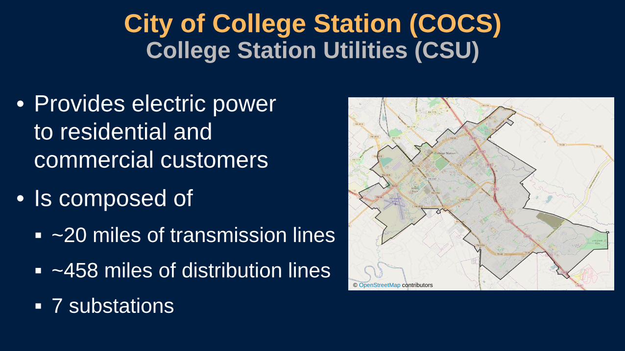
• Two buses electrically connected via normally open tie breaker
• Four feeders per bus supplied from main breaker
• Electromechanical relays
• No bus differential protection
• No breaker failure backup
• No automatic source transfer
• Challenge coordinating for simultaneous fault conditions
Traditional 13.2 kV Distribution Substation
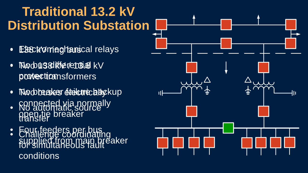
13.2 kV Distribution
Substation for Special Protection
and Control Scheme (SPCS)
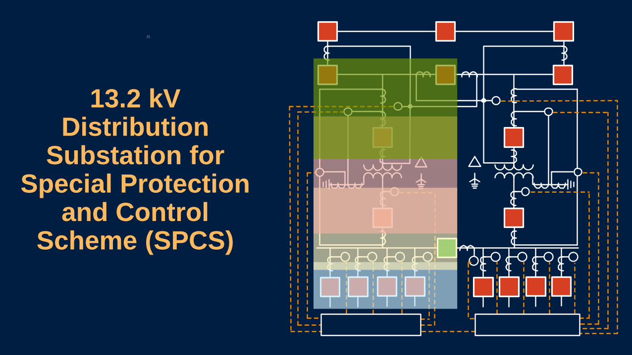
Information Flow Diagram
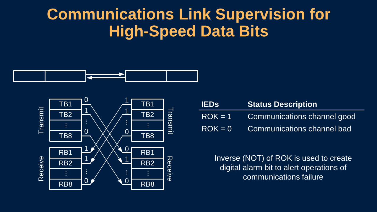
Communications Link Supervision for High-Speed Data Bits
IEDs Status DescriptionROK = 1 Communications channel goodROK = 0 Communications channel bad
Inverse (NOT) of ROK is used to create digital alarm bit to alert operations of
communications failure
TB1TB2
...
TB8
RB1RB2
...
RB8
TB1TB2
...
TB8
RB1RB2
...
RB8
Tran
smit
Rec
eive
Transmit
Receive
01
0
11
0
......
11
0
01
0
......
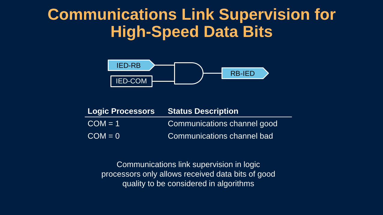
Communications Link Supervision for High-Speed Data Bits
Communications link supervision in logic processors only allows received data bits of good
quality to be considered in algorithms
Logic Processors Status DescriptionCOM = 1 Communications channel goodCOM = 0 Communications channel bad
IED-COMRB-IED
IED-RB
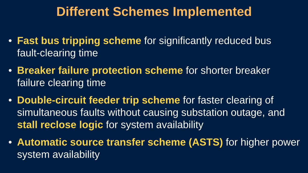
• Fast bus tripping scheme for significantly reduced bus fault-clearing time
• Breaker failure protection scheme for shorter breaker failure clearing time
• Double-circuit feeder trip scheme for faster clearing of simultaneous faults without causing substation outage, and stall reclose logic for system availability
• Automatic source transfer scheme (ASTS) for higher power system availability
Different Schemes Implemented
SCPS Six Major Design Criteria
Dependability Security Selectivity
Resilience Speed Cost
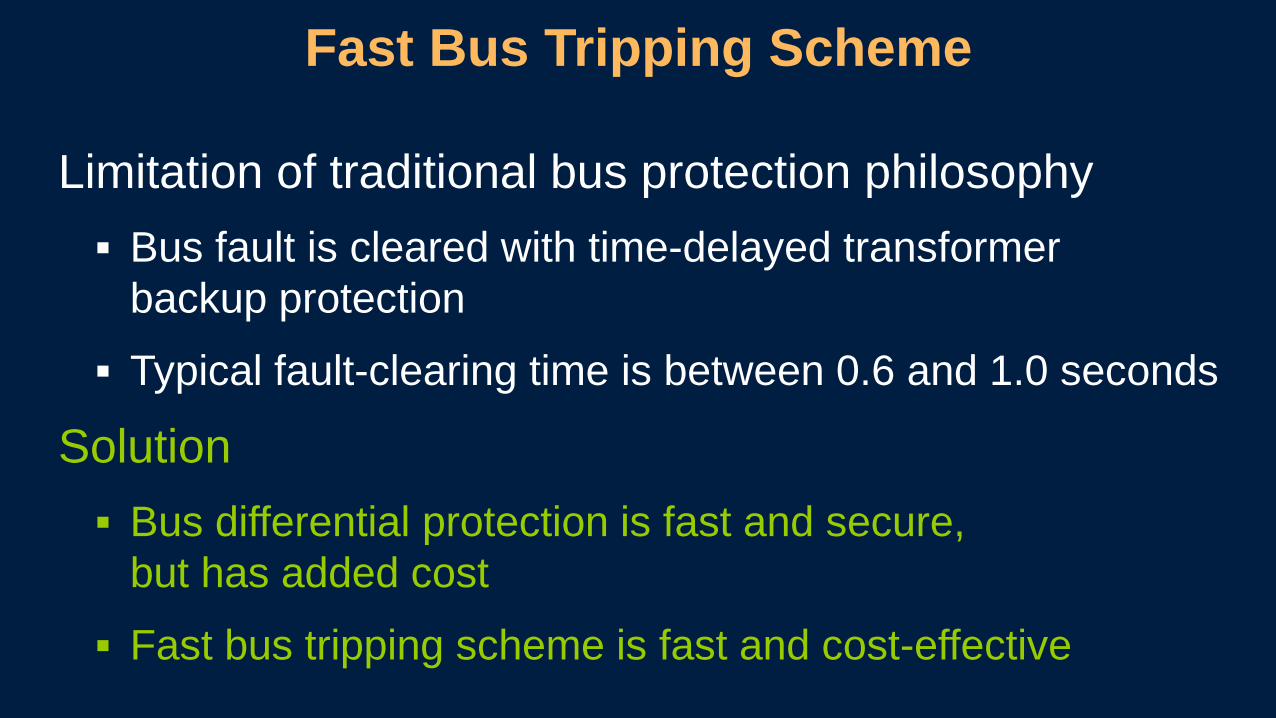
Limitation of traditional bus protection philosophy Bus fault is cleared with time-delayed transformer
backup protection
Typical fault-clearing time is between 0.6 and 1.0 seconds
Solution Bus differential protection is fast and secure,
but has added cost
Fast bus tripping scheme is fast and cost-effective
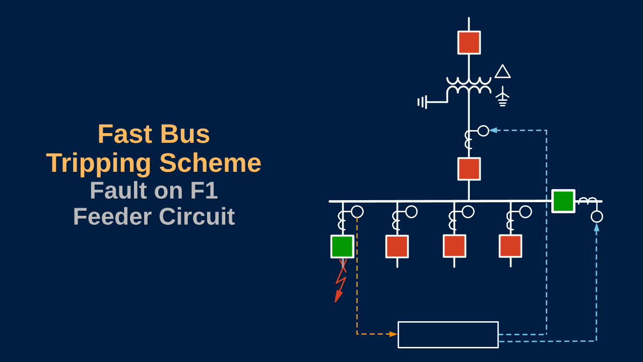
Fast Bus Tripping Scheme
Fast Bus Tripping Scheme
Fault on Bus 1
Fast Bus Tripping Scheme
Fault on F1 Feeder Circuit
Limitation of traditional breaker failure protection philosophy Fault is cleared with upstream inverse-time overcurrent
protection
Long fault-clearing times lead to equipment damage or reduced equipment lifespan
Solution Dedicated, fast breaker failure protection scheme using existing
IEDs and communications backbone
Low implementation cost with minimal wiring
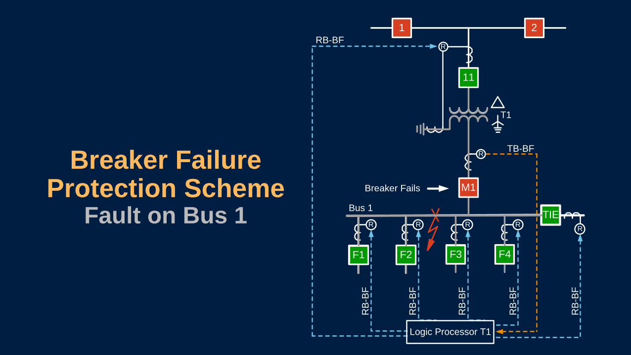
Breaker Failure Protection Scheme
RB
-BF
RB
-BF
RB
-BF
RB
-BF
RB
-BF
RB-BF
Breaker Failure Protection Scheme
Fault on Bus 1 Bus 1
R
RRRR
Logic Processor T1
R
T1
F1 F2 F3 F4
TIE
M1
11
21
R
Breaker Fails
F1 F2 F3 F4
TB-BF
M1
11
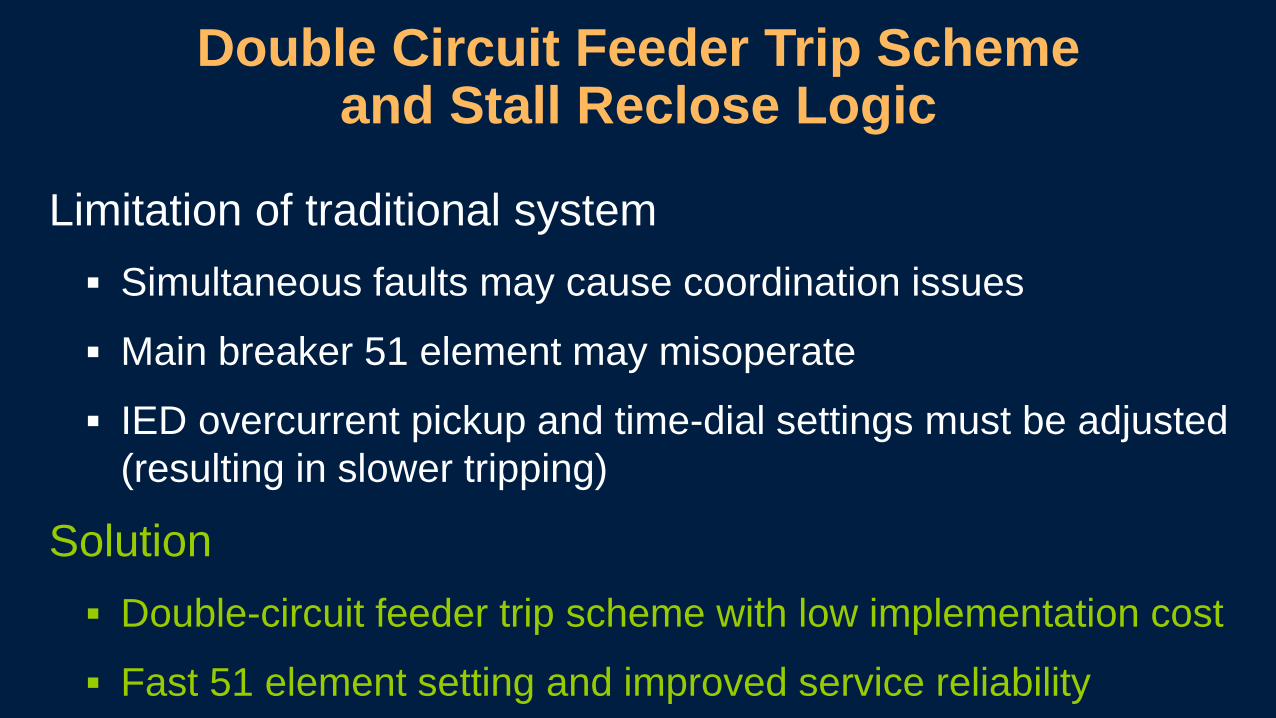
Limitation of traditional system Simultaneous faults may cause coordination issues
Main breaker 51 element may misoperate
IED overcurrent pickup and time-dial settings must be adjusted (resulting in slower tripping)
Solution Double-circuit feeder trip scheme with low implementation cost
Fast 51 element setting and improved service reliability
Double Circuit Feeder Trip Scheme and Stall Reclose Logic
RB
-PU
RB
-PU
RB
-PU
RB
-PU
RB
-PU
RB
-PU
RB
-PU
RB
-PU
RB-PU
TB-P
U
TB-P
U
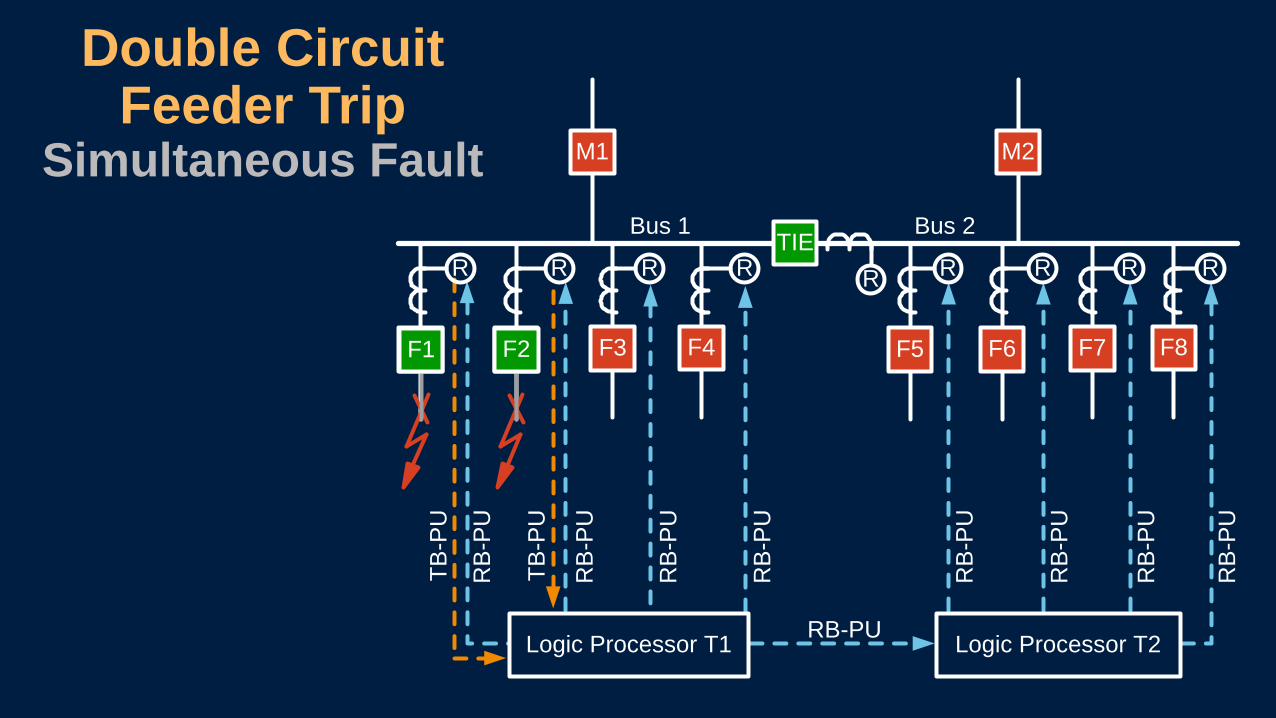
Double Circuit Feeder Trip
Simultaneous FaultBus 2
M2
R
M1
Bus 1TIE
F5
R
F6
R
F7
R
F8
R
F4
R
F3
R
F1 F2
RR
Logic Processor T2Logic Processor T1
F1 F2
TB-S
R
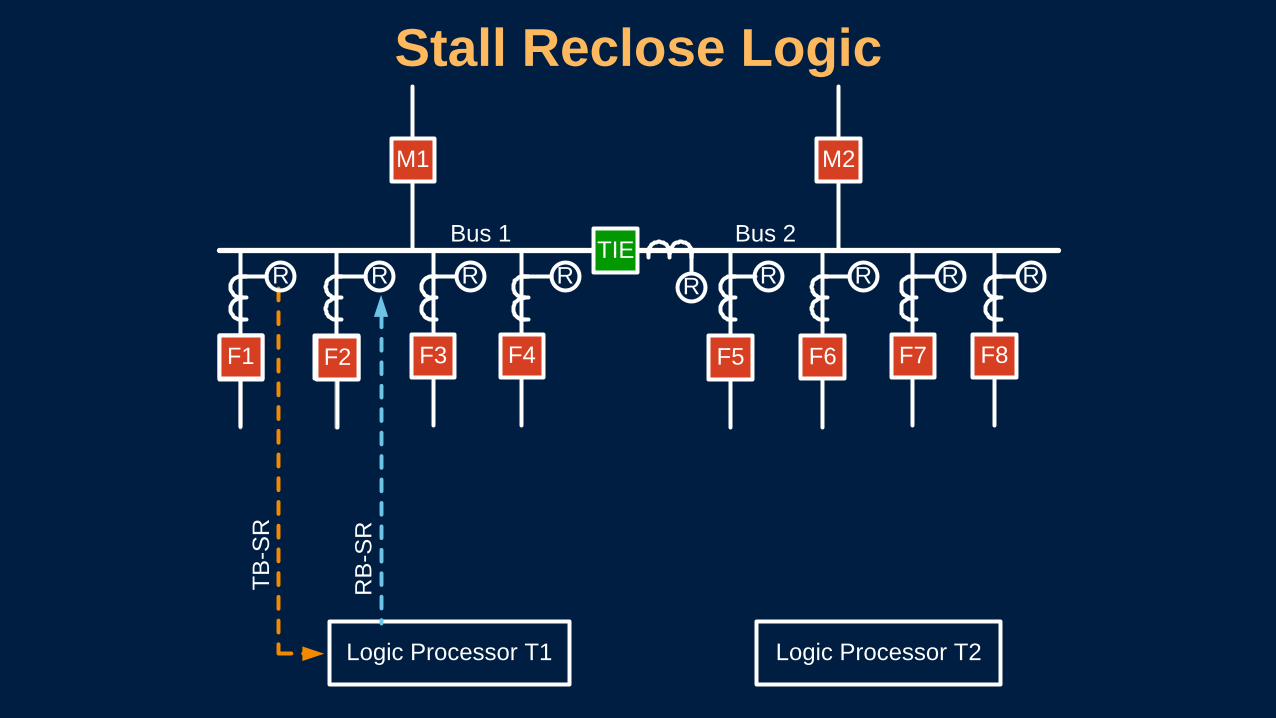
Stall Reclose Logic
Bus 2
M2
R
M1
Bus 1TIE
F5
R
F6
R
F7
R
F8
R
F4
R
F3
R
F1 F2
RR
Logic Processor T2Logic Processor T1
RB
-SR
F1 F2
Limitation of traditional system Less power system availability with more disruption
Long restoration times
Solution ASTS that automatically switches from primary source
to alternate source
Short restoration times to improve power system availability
ASTS
RB
-CLO
SE TB
-NO
FA
ULT
TB-F
AU
LT
SCADA ASTS ENABLE
TB-5
2ATB
-52A
TB-5
2A
ASTSTransformer Fault
Bus 1TIE
11
M1
R
R
Bus 2
22
M2
R
R
Logic Processor T2Logic Processor T1
F2 F3 F4F1 F5 F6 F7 F8
T2T1R
11
M1
F2 F3 F4F1
TIETIE
F2 F3 F4F1
M1
• Multiple SPCSs run in parallel and coordinate with each other as complete, integrated solution
• Other control logic is implemented to improve system availability and dependability Hot-line mode