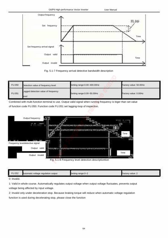
G6/P6 High-performance Vector Inverter User Manual
Excellent performance Control mode VVV/F control mode: Startup torque: 1Hz 120% rated torque Speed adjustment range: 1:120 Speed stabilization precision: ±0.5% Vector control mode: Precise speed sensorless vector control technology realizes AC motor decoupling, enabling the DC motorization of operation control. Startup torque: 0.35Hz 150% rated torque Speed adjustment range: 1:150 Speed stabilization precision: ±0.5% Excellent control performance under speed sensorless vector control mode Realizing AC motor decoupling, enabling the DC motorization of operation control. Figure 1 indicates the four-quadrant operation of motor under speed sensorless vector control. Torque,current,rotating, speed and DC bus voltage have quick response,and motor has stable operation. 0.1s command acceleration/deceleration is realized with rated motor load. Upon the zero-crossing switching of the motor (forward/reverse switching), the current has no phase mutation or oscillation, and the rotating speed has no pulsation. The bus voltage is under stable control. Quick and reliable braking can be realized when decelerating under the condition of braking without power consumption. It is especially suitable for: The reciprocating equipment, such as digital control machine tool, fountain control machine, weaving machine and jacquard.
Torque
Output current
Speed
DC bus voltage
Fig. 1 Quick acceleration/deceleration four-quadrant running in the form of 0Hz→Forward running
50Hz→0Hz→Reverse running 50Hz→0Hz
Realizing real tripless operation With excellent current and voltage control technology, repetitive and alternate acceleration and deceleration is
2
G6/P6 High-performance Vector Inverter User Manual
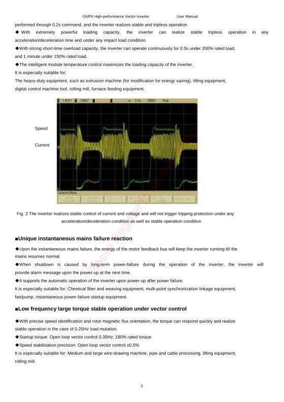
performed through 0.2s command, and the inverter realizes stable and tripless operation.
With extremely powerful loading capacity, the inverter can realize stable tripless operation in any
acceleration/deceleration time and under any impact load condition.
With strong short-time overload capacity, the inverter can operate continuously for 0.5s under 200% rated load,
and 1 minute under 150% rated load.
The intelligent module temperature control maximizes the loading capacity of the inverter.
It is especially suitable for:
The heavy-duty equipment, such as extrusion machine (for modification for energy saving), lifting equipment,
digital control machine tool, rolling mill, furnace feeding equipment.
Speed
Current
Fig. 2 The inverter realizes stable control of current and voltage and will not trigger tripping protection under any
acceleration/deceleration condition as well as stable operation condition
Unique instantaneous mains failure reaction Upon the instantaneous mains failure, the energy of the motor feedback bus will keep the inverter running till the mains resumes normal.
When shutdown is caused by long-term power-failure during the operation of the inverter, the inverter will
provide alarm message upon the power-up at the next time.
It supports the automatic operation of the inverter upon power-up after power failure.
It is especially suitable for: Chemical fiber and weaving equipment, multi-point synchronization linkage equipment,
fan/pump, instantaneous power-failure startup equipment. Low frequency large torque stable operation under vector control With precise speed identification and rotor magnetic flux orientation, the torque can respond quickly and realize stable operation in the case of 0.25Hz load mutation.
Startup torque: Open loop vector control 0.35Hz; 180% rated torque
Speed stabilization precision: Open loop vector control ±0.5%
It is especially suitable for: Medium and large wire-drawing machine, pipe and cable processing, lifting equipment,
rolling mill.
3
G6/P6 High-performance Vector Inverter User Manual
Current
Fig.3 Abrupt increase to full load operation at 0.25Hz under speed sensorless vector control
Unique quick DC braking Within the range of 0 to 60Hz, the inverter can realize back electromotive force elimination and quick DC
braking within 0.3s.
DC current is input in the most efficient way to improve the braking capacity.
There is no initial waiting time for the DC braking.
Special function code setting is provided to cancel the initial waiting time for DC braking.
It is especially suitable for: Lifting equipment, invertible roll table for rolling mill, weaving machine, paper making
production line.
Unique rotating speed tracing function No special hardware detection circuit or special function code setting is needed. Within the range of 0 to 60Hz,
the inverter can complete the identification of the motor rotating speed, rotating direction and phase angle within
0.2s, and start the smooth tracing on the freely rotating motor.
Tracing mode 1: Quick and smooth tracing on the free rotating speed of the motor without any impact.
It is especially suitable for: Fan/pump, the equipment whose operation shall be traced upon the power recovery
after instantaneous power failure.
Current
Rotating speed
Fig. 4 Quick and impactless rotating speed tracing upon the free rotation of the motor
4
G6/P6 High-performance Vector Inverter
High reliability design
Meeting the relevant international product standards
IEC61800-2
IEC61800-3
IEC61000-6
IEC61800-5-1
UL508C
User Manual
General requirements-Rating specifications for low voltage adjustable frequency a.c. power drive systems
EMC product standard including specific test methods
Safety requirements -Electrical, thermal and energy
UL Standard for Safety for Power Conversion Equipment Integrated design Integrated design of hardware interface: The control board, button type operating panel are integrated to
facilitate the operation and maintenance of the user.
Integrated design of software protocol: Terminal 485, universal expansion port SPI protocols are
integrated
(Modbus protocol).
Integrated design of main circuit terminals: 0.75G .to 15G integrated, 18.5G to 75G integrated, to facilitate the
operation and maintenance of the user.
Built-in braking unit design: 0.75G to 15G as standard, 18.5G to 75G as option, to reduce the cost and the
card/communication adapter card, meeting the industry application requirement.
Full series standard common DC bus design: The standard common DC bus scheme can be realized without
modifying the product or adding peripheral circuit. It is applicable to such industry applications as paper making,
chemical fiber, metallurgy and EPS.
Adaptability design Independent duct design: The full series supports the application demand of mounting heatsink out of the cabinet, and is applicable to the applications of spinning machine, wire-drawing machine where there is too much
cotton batting or dust.
Compact structure design: With complete thermal emulation and unique cold plate process, the product has
compact structure, meeting the demand of OEM customers.
Complete system protection design: Based on the complete system design scheme, the PCB adopts protective
coating, the copper bus adopts galvanization, the full series of product adopts sealed key components, the button
type operating panel with potentiometer offers accessories meeting the IP54 requirement, which greatly improve
the protection capacity of the system. It is applicable to the applications with dusty and corrosive environment,
such as wire-drawing machine, printing and dyeing and ceramics.
Wide voltage range design: the DC operating voltage range is DC 360−720V, with mains voltage fluctuation
recording function.
Precise current detection and protection: The full series adopts precise Hall sensor to detect the output current,
meeting the quick real time control and protection requirement of software and hardware, ensuring the
performance and reliability of the system.
Independent power supply for control: The system provides independent switching power DC input port.
External UPS power supply can be realized through option card. It is applicable to the applications of oilfield,
chemical industry and printing and dyeing industry.
Power-up self-detection function: It realizes the power-up detection on the peripheral circuit, such as
motor
grounding, disconnection, greatly improving the reliability of the system.
Comprehensive system protection function: Software/hardware current limiting protection, overcurrent and
5
G6/P6 High-performance Vector Inverter User Manual
overvoltage protection, grounding short circuit protection, overload protection, IGBT short circuit protection,
abnormal current detection protection, abnormal relay contact protection.
Perfect terminal protection function: short circuit and overload protection for the +24V and +10V power supply of
the control terminals, operating panel cable reverse connection protection, input signal cable disconnection and
abnormal analog input protection.
Over-temperature prealarm protection function: Automatic adjustment will be made according to the
temperature to ensure the reliable operation of the product, and maximum operating temperature will be recorded.
Comprehensive switching power protection function: Including switching power output short circuit protection,
overload protection, power-up soft start function, open loop self-locking and voltage limiting protection function,
ensuring the reliability of the system.
6
G6/P6 High-performance Vector Inverter User Manual
Rich and flexible functions Multiple frequency given modes, flexible and convenient for the operation Operating panel setting (digital given). The operating panel can be used to conduct ∨/∧ adjustment on the frequency given. Terminal reference
1) Analog AI1/AI2: 0~10V or 0~20mA; 2) Pulse frequency X8/DI: 0.2Hz~50kHz; 3) Xi terminal: Up/Dn mode independent, able to superpose with any other frequency reference mode.
Communication mode given: International standard Modbus protocol. The above given modes can be switched online. Multiple channels for given input and feedback Under the open loop or analog feedback close loop mode, the given input can define the main and auxiliary calculation relation:
1) Main given input + auxiliary given input; 2) Max (main given input, auxiliary giveninput) 3) Min (main given input, auxiliary given input)
Under the analog feedback close loop mode, the feedback value can also define the main auxiliary calculation relation before it enters the process PID for adjustment control. It is especially suitable for: The continuous and automatic production lines, including paper making, printing and dyeing, packaging and printing, and the temperature difference and pressure difference applications, including the chilled water control of the central air conditioner, the water supply system. Digital operating panel Button type standard TIP connection. The button layout complies with the human engineering principle. One-button function code access and exit, making it easy for the operation. With unique multifunctional button M, the following functions can be defined:
1) JOG; 2) FORWARD 3) REVERSE
Upper computer communication Terminals provide 485 ports, the communication protocol is Modbus, and upper computer monitoring software is provided. Master slave communication control among several inverters can be realized. Parameter upload and download can be realized.
7
G6/P6 High-performance Vector Inverter
Customized functions
Multiple function code display modes FU group menu can displays all the function codes.
Users can self-define the function codes for inquiry and modification
User Manual
Multiple function code encryption modes (to protect the intellectual property of the
customers) Users can set function parameter password protection.
User self-defined parameter display function Users can choose the common parameters displayed by the operating panel and use keyto switch such parameters.
Users can define the parameters displayed upon running and stopping respectively.
Users can define such parameters as voltage,givenfrequency,current.
Users can make secondary development Universal expansion port is provided as standard. Physical port SPI bus, software protocol Modbus.
The ports provide +24V/500mA power supply.
The CPU expansion scheme can realize PLC function.
It supports programming by user to realize process control.
Enhanced function The software filtering time for the AI1, AI2 analog input is settable to enhance the anti-interference capacity. Independent multi-section modification can be made on the AI1, AI2 analog input curve.
Sulti-step speed setting is provided, with 15 speeds as standard.
Standard output frequency is 600Hz,with a maximum output frequency of 2000Hz, it is applicable to such
equipment as vacuum pump, grinding machine, female thread extrusion machine.
With the acceleration/deceleration time up to 10 hours, it is applicable to the bobbiner and other equipment of
the textile industry.
It supports the overload protection with motor temperature feedback.
Independent high-speed pulse input and output ports are provided to realize high-speed pulse cascade
function.
8
G6/P6 High-performance Vector Inverter User Manual
Typical industry applications Digital control machine Compact structure: The size is equal to 70% of the inverter of the same power. Low speed precise processing: The excellent low-frequency torque performance can meet the processing demand of the machine main shaft in low speed condition (when it is operating in motoring state, it can realize a frequency as low as 0.35Hz and output 180% rated torque) Torque and rotating speed index: It can meet the sudden loading and unloading requirement upon the cutting processing, with the dynamic torque response time <20ms and speed stabilization precision of ±0.3%. Special function for wire-drawing machine Operation without swing link: It adopts open loop tension control to realize operation without swing link under speed sensorless control mode. Operation with swing link: The user does not need to adjust the position of the swing link manually. When the system starts up, the swing link will get to the proper position automatically. Powerful tensile capacity: It is suitable for the applications of large and medium wire-drawing machine. It features large torque upon low frequency operation and high speed stabilization precision. Double conversion scheme: It can realize the inverter application of the same power class with precise current control and does not need to upgrade the level. Environment adaptability: Independent duct design, protective coating treatment, high-temperature operation, and digital protection function. Special function for textile Traverse operation function: It can effectively lead the yarn into the yarn carrier on the yarn and chemical fiber equipment to prevent the overlapping of the yarn and facilitate the unreeling. Constant line speed mode: It can effectively prevent the uneven tightness of the yarns from the high speed cone winder to maintain the constant tension. Fixed length calculation: It is convenient for the user to calculate the thread length. When the thread length reaches the preset value, the equipment will be shut down automatically. Extrusion machine energy saving Extrusion machine interface board: It can realize best flow and pressure distribution relation in different processes by receiving the extrusion machine feedback signal to realize optimized energy saving control of motor. Customized process curve: The user does not need to change the inverter parameter when replacing the moulds. The process curve memory can be easily realized. Wide range torque output: Within the set range of pressure and flow, the motor torque output is stable to ensure the quality of the workpiece. Tripless: With extremely powerful loading capacity, the inverter can realize stable tripless operation in any acceleration/deceleration time and under any impact load condition. Green output: It adopts advanced power module drive mode to reduce the interference to the extrusion machine control circuit and sensor. Lifting control Step torque response: It can quickly follow the equipment load change to prevent the runaway situation and ensure the safe production. Four quadrant operation: It can smoothly and quickly switch the forward and reverse motoring and generating
9
G6/P6 High-performance Vector Inverter User Manual
state of the equipment.
Torque monitoring: It can adjust, limit, display and switch the torque output, so as to monitor the operating state
of the equipment.
10
G6/P6 High-performance Vector Inverter User Manual
Unpacking check Check whether wearout was made to packingcase during transport.After unpacking, please check the following items:
Check whether the products coincide with the packing list or not.
Check if any damage was made to the inverter during transport (damage or gap on the body).
Review the inverter's nameplate and check if it is the right model you've ordered.
If you have ordered selected accessories, please also check the accessories.If any damage of the inverter or
the accessories was found, please contact you supplier promptly or directly call 09327444043 / 09824692665.
Inverter use announcements Motor insulation check Motor insulation check should be conducted first, before first long time laydown then reuse and periodic inspection,
in order to prevent inverter from damage due to motor winding insulation failure. Make sure that motor cable is
disconnected from inverter when do isulation check, 500V voltage type megohmmeter is recommended, and
should guarantee the measured resistance is no less than 5 megohm.
Thermal protection of motor
If the capacity of the chosen motor does not match with rated capacity of inverter, especially if inverter's rated
capacity is larger than motor's rated capacity,be sure to adjust motor protection parameters in inverter,or add
thermal relay before the motor in order to protect motor.
Running above power frequency
The inverter's output frequency range is 0Hz~600Hz, If customers need to run inverter above 50 Hz, please
consider the mechanical devices' bearing capacity.
Mechanical devices' vibration
At some output frequencies, inverter may reach the mechanical resonance point of the load device, then avoid by
setting the parameters of the jump frequency.
Motor heat and noise
The inverter outputs PWM voltage wave, with a certain amount of harmonics, so that motor temperature rise,
noise and vibration will increase slightly comparing with running under power frequency condition.
Voltage sensitive devices and capacitors to improve power factor are prohibited.
The innverter outputs PWM wave, if voltage sensitive devices and capacitors to improve power factor are
connected to the output circuit, it will bring about instantaneous large current or even damage to inverter, please
do not use.
Contactor installed between the inverter input and output is not allowed to be used to control start/stop of
inverter. When it is necessary to be used to control start /stop of inverter, there should be an interval of no less
than an hour. Frequently charge and discharge may reduce the life of the capacitors in inverter. If switching
devices such as contactors are equipped between inverter output end and motor, should ensure that the inverter
with no output when on/off operation is conducted, otherwise may easily lead to the inverter inner module
damage.
Use beyond rated voltage
Our inverters are not suitable for usage beyond the allowable operating voltage range which is stipulated by the
manual, otherwise the inverter inner components might be easy to damage.If it is necessary, please use the
appropriate boost or buck units to achieve.
Three-phase input used as two-phase input
Do not allow to use three-phase inverter of this series as two-phase input, otherwise fualt may occur or the
inverter might be damaged. 11
G6/P6 High-performance Vector Inverter User Manual
Lightning surge protection
The series inverters have built-in lightning over-current protection device, with a certain degree of self-protection
capability for lightning. Customers in areas where lightning occurs frequently should install protection devices
before inverter.
Altitude and derating use
For altitude above 1000m areas, the heat dissipation get worse due to the thin air, it is necessary to use by
derating.Please consult our company if you encounter this kind of situation.
Some special use
If customers need to use wiring methods other than the recommended wiring diagram provided in this manual,
such as the common DC bus, please consult our company.
Inverter scrap announcements
) Electrolytic capacitors in the inverter may explode when burn.
) Plastic, rubber and other matierals of inverter may give out harmful poisonous gases when burn, please take
special care.
) Dispose inverter as industrial waste.
Adaptive motor
) Please choose four-pole squirrel cage induction motor as standard adaptive motor,otherwise please be sure to
choose inverter according to motor's rated current. For occasions of driving permanent magnet synchronous
motor, please consult us.
) Cooling fan of the non-inverter motor and rotor shaft are coaxially connected, so fan's cooling effect reduces
as speed decreases,therefore, exhaust fan should be equipped when motor overheating occurs or replaces with
variable-frequency motor.
) The inverter has already built in standard parameters of adaptive motor. According to actual situation, there is
need of doing motor parameter recognization or personalization default values setting to line with the actual value,
otherwise it will affect performance and protective properties.
)Cable or motor inner short circuit may lead to inverter alarm, even blow up. Therefore, insulation short-circuit
test should be carried out on initial installation of the motor and cable, this test also need to be conducted in
routine maintenance.Note: Be sure to cut off the connection between inverter and testing parts before test.
Please read this manual carefully before use the inverter, comprehend every item in order to use correctly.
This manual is a random accessory, be sure to appropriately preserve after use, for viewing at any time.
12
G6/P6 High-performance Vector Inverter
Safety precaution
Description of safety marks:
User Manual
Danger: The misuse may cause fire, severe injury or even death.
Note: The misuse may cause medium or minor injury and equipment damage.
Use
Danger:
Do not use the damaged or uncompleted inverter, otherwise, injury may occur!
Please use the motor above isolation class B,otherwise,electric shock may occur!
This series of inverter is used to control the variable-speed operation of three-phase motor and cannot be used
for single-phase motor or other applications. Otherwise, inverter failure or fire may be caused.
This series of inverter cannot be simply used in the applications directly related to the human safety, such as
the medical equipment.
This series of inverter is produced under strict quality management system. If the inverter failure may cause
severe accident or loss, safety measures, such as redundancy or bypass, shall be taken. Goods acceptance
Note:
Check carefully whether damage or savage unloading was made to the goods,Ifsrews loose or lack parts is
found, the inverter cannot be installed. Otherwise, even bigger lose or accident may be caused. Installation environment
Note:
When inverter is installed in a control cabinet, the cabinet should equip with ventilation cooling fan meeting
inverter requirement,to ensure the inner temperature of the cabinet below 50. Must make internal hot air
smoothly discharge, and cold air inflow into the cabinet, so as to extend the service life and stable operation for
users' use!
Prevent cable cuts or screws entering the inverter, otherwise the inverter maybe damaged!
Please install on apyrous material like metal, keep away from flammable materials, otherwise, fire may occur! Wiring Danger: The wiring must be conducted by qualified electricians. Otherwise, electric shock mayoccur.
Inverter must be disconnected with power supply be breaker, otherwise, fire alarm may occur.
Please make sure the power supply is off before wiring, otherwise, electric shock may occur.
The grounding terminal ―Eǁ must be reliably grounded, otherwise, inverter shell may be electrified and exits the
risk of electric shock.
13
G6/P6 High-performance Vector Inverter User Manual
Main circuit terminals must be carefully checked. Wiring must be operated in accordance with the formal wiring standard.Shall not cheat on workmanship and materials or operate not according to the ruls. Avoid short circuit or
terminal contact undesirable caused fever leads to fire or damage to the equipment. Wiring
Note: The three-phase power supply cannot connect to output terminals U/T1, V/T2 and W/T3, otherwise, the inverter may be damaged.
It is forbidden to connect the output terminal of the inverter to the capacitor or LC/RC noise filter with phase
lead, otherwise, the internal components of the inverter may be damaged.
Please confirm that the power supply phases, rated voltage are consistent with that of the nameplate,
otherwise, the inverter may be damaged.
Do not perform dielectric strength test on the inverter, otherwise, the inverter may be damaged.
The wires of the main circuit terminals and the wires of the control circuit terminals shall be laid separately or in
a square-crossing mode, otherwise, the control signal may be interfered.
The wires of the main circuit terminals shall adopt lugs with insulating sleeves.
The inverter input and output cables with proper sectional area shall be selected according to the inverter
power.
When the length of the cables between the inverter and the motor is more than 100m, it is suggested to use
output reactor to avoid the inverter failure caused by the overcurrent of the distribution capacitor.
Inverter with standard configuration of DC reactor,must connect DC reactor between ⊕ 1, ⊕ 2
terminals,otherwise inverter will do not disply after power on.
Check before operation
Danger: Please confirm whether power source voltage coincides with the inverter voltage, input andoutput wiring is correct, and check carefully whether there is short in the peripheral circuit, the circuit is fastened, otherwise
inverter may be damaged!
Inverter needs no withstand voltage test which has been done before delivery, otherwise electric shock may
occur!
Make sure that all the peripheral accessories are connected according to the circuit diagram provided by the
manual, otherwise electric shock may occur!
Charged commissioning
Danger:
Close the cover board then power on, otherwise electric shock may occur! Power supply can only be connected after the wiring is completed and the cover is installed. It is forbidden to
remove the cover in live condition, otherwise,electric shock may occur.
When the inverter is powered on, even when it is in the stop state, the terminals of the inverter are still live. Do
not touch the inverter terminals, otherwise electric shock may be caused.
The failure and alarm signal can only be reset after the running command has been cut off. Otherwise, personal
injury may be caused. 14
G6/P6 High-performance Vector Inverter User Manual
Early on powering on, inverter carries out security detection to peripheral circuit automatically, at the moment, do not touch the U、V、W terminals or motor terminals, otherwise electric shock may occur! Note: When auto failure reset or power failure restart function is set, isolation measures shall betaken for the mechanical equipment, otherwise, personal injury may be caused.
When it is used on lifting equipment, mechanical contracting brake shall also be equipped.
Do not control the inverter's start/stop by connect/disconnect the power supply, otherwise equipments might be
damaged!
Do not touch the inverter terminals (including the control terminals), otherwise electric shock may occur!
If parameters recognition is needed, please note that the motor may hurt people during revolving, otherwise
accident may occur!
Do not chang factory parameters of the inverter at discretion, otherwise equipments might be damaged!
If restart function was chosen, please keep away from the machines, otherwise human injury may occur!
Do not touch the cooling fan or the discharge resistor, otherwise burn may occur!
In the applications with industrial frequency and variable frequency switching, the two contactors for controlling
the industrial frequency and variable frequency switching shall be interlocked.
Maintenance, inspection
Danger: In the power-on state, please do not touch the inverter terminals, otherwise, there exists therisk of electric shock.
If cover is to be removed, the power supply must be disconnected first.
Wait for at least 10 minutes after power off or confirm that the CHARGE LED is off before the maintenance and
inspection to prevent the harm caused by the residual voltage of the main circuit electrolytic capacitor to persons.
The components shall be maintained, inspected or replaced by qualified electricians. Note: The circuit boards have large scale CMOS IC. Please do not touch the board to avoid thecircuit board damage caused by static. Danger: It is forbidden to modify the inverter unauthorizedly, otherwise, personal injury may becaused.
1.2 Product model description ..................................................................................................................... 18
1.3 Series model description........................................................................................................................ 18
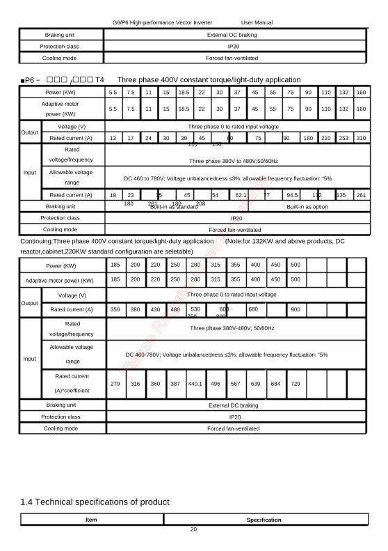
1.4 Technical specifications of product......................................................................................................... 20
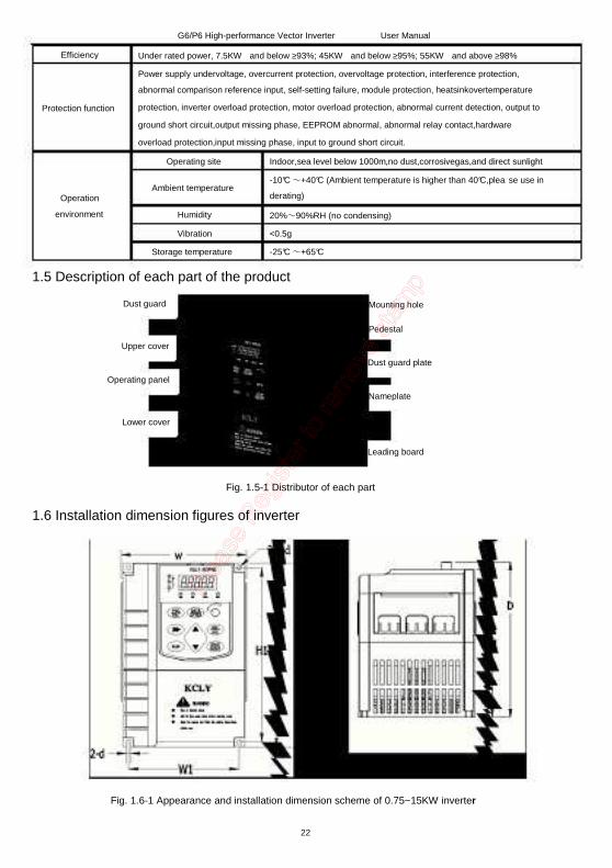
1.5 Description of each part of the product................................................................................................... 22
1.6 Installation dimension figures of inverter ................................................................................................ 22
1.7 Description of optional accessories........................................................................................................ 25
1.7.1 Option description of DC reator........................................................................................................... 25
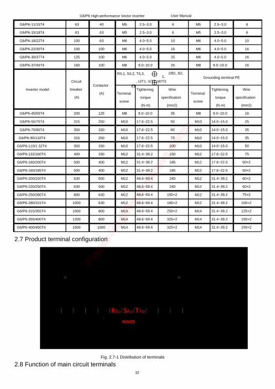
2.8 Function of main circuit terminals........................................................................................................... 32
2.9 Matters for attention for main circuit wiring ............................................................................................. 34
2.9.1 Power supply wiring............................................................................................................................ 34
2.9.2 Motor wiring........................................................................................................................................ 34
2.10.1Control circuit and main circuit connection ......................................................................................... 37
2.10.2 Arrangement sequence of the control circuit terminals....................................................................... 38
2.10.3 Description of control circuit terminals ............................................................................................... 38
2.10.4 Analog input terminals....................................................................................................................... 39
2.10.5 Wiring mode of the multi-functional input/output terminals ................................................................. 40
2.10.6 Wiring mode of digital output terminal adopts internal and external power supply .............................. 42
2.10.7 Description of control circuit jumper and other interfaces................................................................... 42
Chapter 3 Using Instructions of InverterOperation…………………………………………………………………………………………………………………………………………………………………………………….…………………………………………………….……………………..44
3.1 Introduction to operation panel............................................................................................................... 43
3.2 Descriptions of indicators....................................................................................................................... 43
3.3 Descriptions of keys function ................................................................................................................. 44
3.4 Nixie tube Display and character recognition.......................................................................................... 44
G6/P6 High-performance Vector Inverter User Manual
Chapter 4 List of Function code .................................................................................................................... 46
Chapter 5 Description of Function Code....................................................................................................... 57
5.2 Motor parameters .................................................................................................................................. 65
5.3 V/F curve setting and torque adjustment parameter ............................................................................... 65
5.5 Multi-step speed and simple PLC........................................................................................................... 75
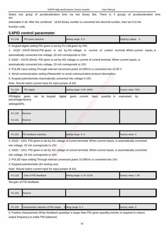
5.6 PID control paranmeter.......................................................................................................................... 78
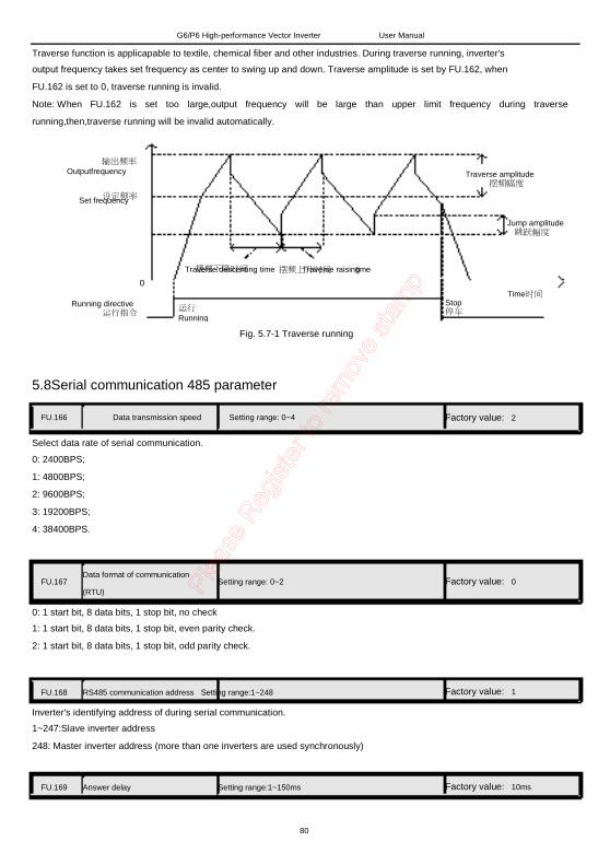
5.7 Traverse control parameter.................................................................................................................... 79
5.8 Serial communication 485 parameter..................................................................................................... 80
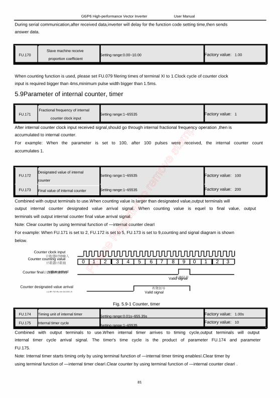
5.9 Parameter of internal counter, timer ....................................................................................................... 81
5.10 Missing phase protectionof input and output......................................................................................... 82
5.11 Password protection and initialization parameter .................................................................................. 82
Chapter 6 Fault Alarm and Countermeasures............................................................................................... 85
6.1 Fault and Alarm ..................................................................................................................................... 85
6.1.1 Fault indication and fault reset ............................................................................................................ 85
6.2 Fault alarm and contermeasures............................................................................................................ 85
6.3 Solutions of common fault...................................................................................................................... 87
6.3.1 No display after power on ................................................................................................................... 87
6.3.2 Motor does not run after inverter ran ................................................................................................... 87
Chapter 7 Serial 485 (MODBUS) Communication Protocol .......................................................................... 88
7.1 Composition of MODBUS communication.............................................................................................. 88
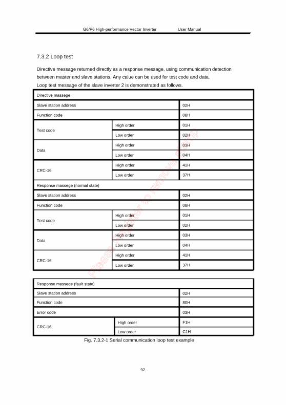
7.3.2 Loop test ............................................................................................................................................ 92
7.3.3 Write in of multiple memory registers .................................................................................................. 93
7.3.4 Data save directive ............................................................................................................................. 94
7.3.5 Broadcast sending data ...................................................................................................................... 94
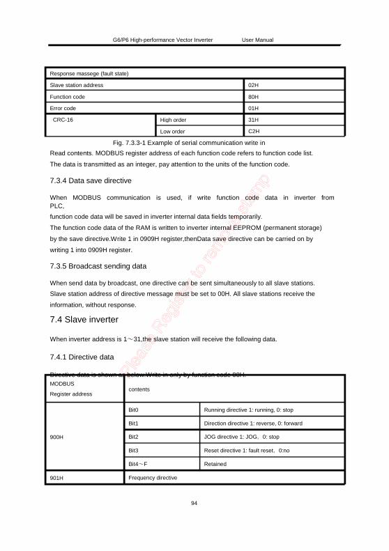
7.4.1 Directive data ..................................................................................................................................... 94
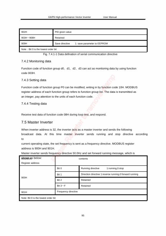
7.4.3 Setting data ........................................................................................................................................ 95
7.4.4 Testing data ........................................................................................................................................ 95
G6/P6 High-performance Vector Inverter User Manual
Chapter 1 Introduction to G6/P6 Series Inverter 1.1 Product nameplate description
Product model
Power class Input specification
Outputspecification
Product barcode
Marketing
MODEL:UVT-G6/P6-22/30T4
POWER: 22KW/30KW
INPUT: AC3PH 380V-480V50/60Hz 69A/86A
OUTPUT:AC3PH 0-380V
S/N:
0-300Hz 45A/60A
CE
UV TECH. PASSED
1.2 Product model description The digits and letters in the inverter model field on the nameplate indicate such information as brand code, product series, power supply class, power class and software/hardware versions.
UVT - G6/P6- 22/30T4 - Rx - Yx
UVtech G: Heavy-duty type P: Light-dutytype Z:Extrusion machine type V:Spinning type Q:Lifting type 6:Software upgrade version, open-loop vector control
compensation(speed compensation),auto voltage regulation( AVR),
speed tracking start function,DC braking when start,DC braking when
stop,restart after instantaneous power failure,auto fault reset,overcurrent
compression when accelerating,overcurrent descent frequency function
at constant speed,overvoltage compression when decelerating,jump
frequency function, carrier frequency automatic adjustment,automatic
economic running,simple one drive two water supply function,16 steps
multi-step speed running,simple PLC program running,traverse function
for spinning,closed-loop PID adjustment control.
3 kinds of control mode:keypadcontrol,analog terminal control,serial
communication control
Digital set,analog voltage set,analog current set,pulse input set,serial
communication port set; through various method to combination switch.
8 digital input terminals,up to 25 kinds of self-defined function,Compatible
with active PNP input or NPN input,one can be used as a high speed
pulse input;
2 analog analogterminals,can receive voltage signals (0~10V) or current
signal (0~20mA);
2 open-collector output terminals,up to 16 kinds of self-defined function;
2 relay output terminals,up to 20 kinds of self-defined function
2 analog output terminals,up to 10 kinds of self-defined function;can
output voltage signals (0~10V) or current signal (0~20mA);
21
G6/P6 High-performance Vector Inverter User Manual
Efficiency
Protection function
Under rated power, 7.5KW and below ≥93%; 45KW and below ≥95%; 55KW and above ≥98% Power supply undervoltage, overcurrent protection, overvoltage protection, interference protection,
No special instructions Inverter models Customers can add by their own Inverter models
1.7.2 Braking resistor selection guideline When the control device driven by inverter needs to brake quickly, braking unit should be used to release the power back to DC bus when motor braking.
Braking resistor selection of different voltage classes and different power classes inverters is shown as below
G6/P6 High-performance Vector Inverter User Manual
1.8Connection description of extrusion machine's signal Board UV TECH is anIO expansion optional component of extrusion machine promoted by our company, matingwith G6/P6 series inverters.It can directly inputs 0~1ADC current signals(through CI~COM terminals)or 0~24VDC voltage signals (through VI~COM terminals). After opto-couplersisolation processing, the signals can be converted into 0~10V voltage signal then internally connecting to inverterVCIinterface directly through row cable, users don't need to additionally connect analog signalcable. Note: When extrusion machine signal board is used, external analog input of AI1, AI2can not be used.
Fig. 1.8-1Connection of extrusion machine signal board
Wiringdescription of extrusionmachine:
One of the two connection mathods can be used,but cannot be used at the same time.
1. Control board of the extrusion machine outputs 0~24V voltage to injection molding signal board, VI connects
positive voltage end, COM connects negative voltage end.
2. Control board of the extrusion machine outputs 0~1A current to injection molding signal board, CI connects
current inflow end(Relative to signal board of extrusion machine), COM connects current outflow end(Relative to
the signal board of extrusion machine).
27
G6/P6 High-performance Vector Inverter User Manual
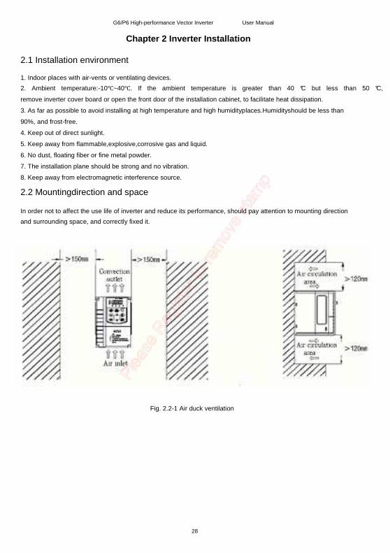
Chapter 2 Inverter Installation 2.1 Installation environment 1. Indoor places with air-vents or ventilating devices. 2. Ambient temperature:-10~40. If the ambient temperature is greater than 40 °C but less than 50 °C, remove inverter cover board or open the front door of the installation cabinet, to facilitate heat dissipation. 3. As far as possible to avoid installing at high temperature and high humidityplaces.Humidityshould be less than 90%, and frost-free. 4. Keep out of direct sunlight. 5. Keep away from flammable,explosive,corrosive gas and liquid. 6. No dust, floating fiber or fine metal powder. 7. The installation plane should be strong and no vibration. 8. Keep away from electromagnetic interference source.
2.2 Mountingdirection and space In order not to affect the use life of inverter and reduce its performance, should pay attention to mounting direction and surrounding space, and correctly fixed it.
Fig. 2.2-1 Air duck ventilation
28
G6/P6 High-performance Vector Inverter User Manual
2.3Removal and mounting of operating panel and cover 2.3.1 Removal and mounting of operating panel
Fig. 2.3.1-1 Removal of operating panel Fig.2.3.1-2 Mounting of operating panel
2.3.2 Removal and mounting of covers of inverter with plastic enclosure
Fig.2.3.2-1 Removal of lower cover Fig.2.3.2-2 Removal of upper cover
Fig.2.3.2-3 Mounting of upper coverFig.2.3.2-4 Mounting of lower cover
29
G6/P6 High-performance Vector Inverter
2.4 Connection peripheral devices
User Manual
AC Power supply
Circuit breaker or
leakage circuit breaker
AC Contactor
Input
AC reactor
Input AC Noise filter DC reactor
Inverter
Grounding
Output AC Noise filter Braking resistor
Output AC reactor
Motor
Grounding
30
G6/P6 High-performance Vector Inverter User Manual
2.5 Description of peripheral devices for main circuit
The capacity of the circuit breaker shall be 1.5 to 2 time of the rated current of the inverter. Circuit breaker
Leakage circuit
breaker
Contactor
Input AC reactor
or DC reactor
Input noise filter
Thermal protection
relay
Output noise filter
Output AC reactor
The time features of the circuit breaker shall fully consider the time features of the inverter overload
protection.
Because the inverter output is the high-frequency pulse output, there will be high-frequency leakage
current. Special leakage circuit breaker shall be used when installing leakage circuit breaker at the input
end of the inverter.
It is suggested that B type leakage circuit breaker be used, and the leakage current value shall be set
as
300mA.
Frequent open and close of contactor will cause inverter failure, so the highest frequency for the open and
close of contactor shall not exceed 10 times/min.
When braking resistor is used, to void the overtemperature damage of the braking resistor,
thermal
protection relay with braking resistor overtemperature detection shall be installed to disconnect
the
contactor at the contact control power side of the thermal protection relay.
1. The inverter power supply capacity is more than 600kVA or 10 times of the inverter capacity.
2. If there is switch type reactive-load compensation capacitor or load with silicon control at the same power
node, there will be high peak current flowing into input power circuit, causing the damage of the
rectifier
components.
3. When the voltage unbalancedness of the three-phase power supply of the inverter exceeds 3%, the
rectifier component will be damaged.
4. It is required that the input power factor of the inverter shall be higher than 90%.
When the above situations occur, install the AC reactor at the input end of the inverter or DC reactor to the
DC reactor terminal.
The noise input from the power end to the inverter or output from the inverter to the power end can
be
reduced.
Although the inverter has motor overload protection function, when one inverter drives two or more motors
or multi-pole motors, to prevent the motor overtemperature failure, thermal protection relay shall
be
installed between the inverter and each motor, and the motor overload protection parameter P9.16 shall be
set as ―2ǁ (motor protection disabled).
When the output end of the inverter is connected with noise filter, the conduction and radiation interference
can be reduced.
When the cable connecting the inverter and the motor is longer than 100m, it is suggested to install
AC
output reactor to suppress the high-frequency oscillation to avoid the damage to motor insulation, large
leakage current and frequent inverter protective action.
Terminal name and function description Three-phase AC input terminal
DC reactor connecting terminal, short circuited with copper bus upon delivery. DC power input terminal; DC output terminal of external braking unit Three-phase AC output terminal Grounding terminal PE
Internal braking unit option for G6/P6-18.5/22T4~G6/P6-75/90T4
R/L1 S/L2 POWER
T/L3 B1 B2 OPTION
U/T1
E
V/T2 MOTOR
W/T3
Terminal symbol R/L1, S/L2, T/L3
B1, *
Terminal name and function description Three-phase AC input terminal
DC power supply input terminal *
B1, B2 *
U/T1, V/T2, W/T3
Connecting terminal of braking resistor Three-phase AC output terminal Grounding terminal PE
*
Note:Products with tandard built-in braking unit can realize DC bus and braking function at the same time, if DC
reactor and braking function are needed to be realized at the same time,please contact the
manufacturer.Meanwhile, main circuit terminals B1,B2,are correspondingly changed to ⊕1,⊕2/B1,B2.
33
G6/P6 High-performance Vector Inverter
G6-90T4~G6-400T4 and P6-110T4~P6-450T4
User Manual
G6-90T4~G6-400T4 and P6-110T4~P6-450T4inverters employ top in bottom out wiring
type
POWER
R/L1 S/L2 T/L3
⊕1 ⊕2 OPTION
U/T1 V/T2 MOTOR
W/T3
Terminal symbol R/L1, S/L2, T/L3 ⊕1,⊕2
⊕2, U/T1、V/T2、W/T3
Terminal name and function description Three-phase AC input terminal Connecting terminal of DC reactor;if don't connectreactor,inverter do not display after power on DC power supply input terminal;DC output terminal of external braking unit
Three-phase AC output terminal
Grounding terminal PE
2.9 Matters for attention for main circuit wiring 2.9.1 Power supply wiring It is forbidden to connect the power cable to the inverter output terminal, otherwise, the internal components of the inverter will be damaged. To facilitate the input side overcurrent protection and power failure maintenance, the inverter shall connect to the power supply through the circuit breaker or leakage circuit breaker and contactor. Please confirm that the power supply phases, rated voltage are consistent with that of the nameplate, otherwise, the inverter may be damaged. 2.9.2 Motor wiring It is forbidden to short circuit or ground the inverter output terminal, otherwise the internal components of the inverter will be damaged. Avoid short circuit the output cable and the inverter enclosure, otherwise there exists the danger of electric shock. It is forbidden to connect the output terminal of the inverter to the capacitor or LC/RC noisefilter with phase lead, otherwise, the internal components of the inverter may be damaged. When contactor is installed between the inverter and the motor, it is forbidden to switch on/off the contactor during the running of the inverter, otherwise, there will be large current flowing into the inverter, triggering the inverter protection action. Length of cable between the inverter and motor If the cable between the inverter and the motor is too long, the higher harmonic leakage current of the output end will cause adverse impact on the inverter and the peripheral devices. It is suggested that when the motor cable is longer than 100m, output AC reactor be installed. Refer to the following table for the carrier frequency setting.
34
G6/P6 High-performance Vector Inverter User Manual
Length of cable between the
inverter and motor
Carrier frequency (PA.00)
2.9.3 Grounding wiring
Less than 50m Less than 15kHz
Less than 100 m Less than 10kHz
More than 100m Less than 5kHz
The inverter will produce leakage current. The higher the carrier frequency is, the larger the leakage current will
be. The leakage current of the inverter system is more than 3.5mA, and the specific value of the leakage current is
determined by the use conditions. To ensure the safety, the inverter and the motor must be grounded.
The grounding resistance shall be less than 10ohm. For the grounding wire diameter requirement, refer to
2.6lectotype of main circuit peripheral devices.
Do not share grounding wire with the welding machine and other power equipment.
In the applications with more than 2 inverters, keep the grounding wire from forming a loop.
Correct Wrong
Fig. 2.9.3-1 Correct and wrong connection of grounding wiring 2.9.4 Countermeasures for conduction and radiation interference
Inverter
Input filter Filtering cable
Fig. 2.9.4-1 Conection of onduction and radiation interference solutions
When the noise filter is installed, the wire connecting the filter to the inverter input power end shall be as short
as possible.
The filter enclosure and mounting cabinet shall be reliably grounded in large area to reduce the back flow
impedance of the noise current Ig.
The wire connecting the inverter and the motor shall be as short as possible. The motor cable adopts 4-core
cable, with the grounding end grounded at the inverter side, the other end connected to the motor enclosure. The
motor cable shall be sleeved into the metal tube.
The input power wire and output motor wire shall be kept away from each other as long as possible.
The equipment and signal cables vulnerable to influence shall be kept far away from the inverter.
Key signal cables shall adopt shielding cable. It is suggested that the shielding layer shall be grounded with
360-degree grounding method and sleeved into the metal tube. The signal cable shall be kept far away from the
35
G6/P6 High-performance Vector Inverter User Manual
inverter input wire and output motor wire. If the signal cable must cross the input wire and output motor wire, they
shall be kept orthogonal.
When analog voltage and current signals are adopted for remote frequency setting, twinning shielding cable
shall be used. The shielding layer shall be connected to the grounding terminal PE of the inverter, and the signal
cable shall be no longer than 50m.
The wires of the control circuit terminals RA/RB/RC and other control circuit terminals shall be separately
routed.
It is forbidden to short circuit the shielding layer and other signal cables and the equipment.
When the inverter is connected to the inductive load equipment (e.g. electromagnetic contactor, relay and
solenoid valve), surge suppressor must be installed on the load equipment coil, as shown in Fig.3-5.
压敏
电阻 感性
load 负载
Inductive 感性 load 负载
Inductive Inductive 感性
load 负载
DC 24V AC 220V AC 220V
Fig. 2.9.4-2 Application of inductive load surge suppressor
36
r o
t
s i s
e r o
z
e i P
G6/P6 High-performance Vector Inverter
2.10 Terminal wiring
2.10.1Control circuit and main circuit connection
User Manual
37
G6/P6 High-performance Vector Inverter 2.10.2Arrangement sequence of the control circuit terminals
User Manual
2.10.3 Description of control circuit terminals
Type Terminal Terminal function
symbol description
+10V
AI1
Analog 10V power supply
Analog frequency setting 1
Analog
input AI2
GND
X1/RUN
X2/REV
X3
Input terminal X4
X5 Digital
input X6/JOG
X7/RST
X8/DI
+24V
COM
AO1
Analog frequency setting 2
Analog common port Multi-function input terminal
X1/RUN Multi-function input terminal
X2/REV Multi-function input terminal
X3 Multi-function input terminal
X4 Multi-function input terminal
X5 Multi-function input terminal
X6/JOG Multi-function input terminal
X7/RST Multi-function input terminal
X8/DI DC24V power supply positive
end DC24V power supply negtive
end
Analog monitoring output 1
Technical specification Output capacity: below 50mA DC: 0~10V or 0.20 mA (resolution
Analog monitoring output 2 Analog monitoring common
port
Voltage or current output; Leave
factory setting:output frequency Voltage or current output; Leave
factory setting:output current
0V
Output capacity:
Voltage: 0~10V, below
2mA;
Current: 0~20mA,
below 10V
38
G6/P6 High-performance Vector Inverter
Photo coupler
output 1 Photo coupler
output 2 Photo coupler output common
port
User Manual
Y1
Digital
output Y2
COM
Leave factory setting: inverter running
Leave factory setting: running
frequency reaches set value
0V
Open collector output; Photo coupler output
capacity:
DC36V,below 50mA .
Relay
output
RA1RA2 A node output RB1RB2 B node output
RC1RC2
+24V
Power supply
PW
Communication
+485 -485 GND
Node point output common
port DC24V power supply positive
end
Multi-function input common
port
RS485 communication port + RS485 communication port - 485 common port
Leave factory setting: shutdown fault
occur during running
RA—RC: Normally closed
RB—RC: Normally open
Node capacity:
AC250V, below 2A ;
DC30V,below 1A.
Leave factory standard: +24V short circuit with PW by short circuit plate
Output capacity: below
500mA; +24V short circuit with PW by short
circuit plate when leave
factory.
RS485 interface for MODBUS
communication use
MEMOBUS protocol
Max38.4kBPS
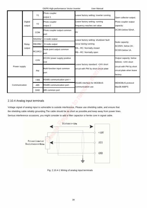
2.10.4 Analog input terminals Voltage signal of analog input is vulnerable to outside interference, Please use shielding cable, and ensure that the shielding cable reliably grounding.The cable should be as short as possible,and keep away from power lines.
Serious interference occasions, you might consider to add a filter capacitor or ferrite core in signal cable.
Fig. 2.10.4-1 Wiring of analog input terminals
39
G6/P6 High-performance Vector Inverter User Manual
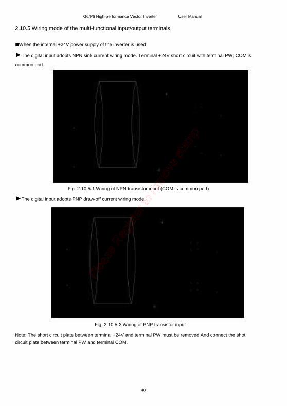
2.10.5 Wiring mode of the multi-functional input/output terminals When the internal +24V power supply of the inverter is used
The digital input adopts NPN sink current wiring mode. Terminal +24V short circuit with terminal PW; COM is
common port.
Fig. 2.10.5-1 Wiring of NPN transistor input (COM is common port)
The digital input adopts PNP draw-off current wiring mode.
Fig. 2.10.5-2 Wiring of PNP transistor input Note: The short circuit plate between terminal +24V and terminal PW must be removed.And connect the shot
circuit plate between terminal PW and terminal COM.
40
G6/P6 High-performance Vector Inverter
When the external power supply is used
User Manual
The digital input adopts NPN sink current wiring mode.External 24V power supply is used, terminal COM is common port.
Fig. 2.10.5-3 Wiring of NPN transistor input Note: The short circuit plate between terminal P24 and terminal PLC must be removed.
When PNP draw-off current wiring mode is adopted,negative end of external power supply connects to
terminal PW;Positive end of the external power supply is common port.Voltage range of external power supply is
9~30V.
Fig. 2.10.5-4 Wiring of NPN transistor inputdraw-off current
41
G6/P6 High-performance Vector Inverter User Manual
2.10.6 Wiring mode of digital output terminal adopts internal and external power supply
Wiring mode of digital output when open-collector output Y1,Y2 adopts internal +24V
Fig.2.10.6-1Digital output adopts internal power supply
Wiring mode of digital output when open-collector output Y1,Y2 adopts external power supply
Fig. 2.10.6-1 Digital output adopts external power supply
Note: When external power supply is adopted,please connect negative end of external power supply with terminal
COM.Maximun current of open-collecter output is 50mA.If external load is relay, please parallel a fly-wheel diode
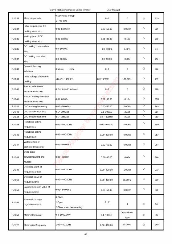
with it. Please correctly install the fly-wheel diode, otherwise inverter internal panel and DSP can be damaged. 2.10.7 Description of control circuit jumper and other interfaces
Function description Select AI1 analog input quantity:V voltage 0~10V; I current 0~20mA Select AI2 analog inputquantity:V voltage 0~10V; I current 0~20mA Select AO1 to output analog quantity:V voltage 0~10V; I current 0~20mA Select AO2 to output analog quantity:V voltage 0~10V; I current 0~20mA Keypad interface Dedicated interface for extrusion
Fig. 2.10.7-1Description of control circuit jumper and other interfaces
42
Leave factory setting 0-10V 0-20mA 0-10V 0-20mA
G6/P6 High-performance Vector Inverter User Manual
Chapter 3 Using Instructions of InverterOperation 3.1 Introduction to operation panel
3.2 Descriptions of indicators
Symbol of indicator
Hz
A
V
Hz+A Hz+V
Name
Frequency indicator
Current indicator
Voltage indicator
speed indicator
PID mode indicator
Inverter temperature value
indicator Hz+A+V
RUN Running status indicator
DIR Run reverse indicator
LOCAL
TRIP
Running command given
mode indicator
Fault alarm indicator
State description On: Current display parameter is set frequency
Flash: Current display parameter is running frequency
On: Current display parameter is current
On: Current display parameter is voltage
Flash: Current display parameter is DC bus voltage
On: Current display parameter is speed
On: Current given mode is PID closed-loop given
Flash: Current feedback mode is PID closed-loop feedback
On: Current detected temperature value of inverter inner On: Inverter is in running or JOG state
Flash: Inverter is decelerating to stop
Off: Inverter is in stop state On: Inverter is in reverse state
Flash: Inverter is forward & reverse switching
Off:IInverter is in forward state On: Operation panel control mode (local control)
Off: Terminals or serial communication control mode On: Minor fault prealarm (overcurrent, overvoltage)
Off: Outputcurrent of inverter and bus voltage are normal.
43
r o t
a c i
d n i
t i n
U
r o t
a c i
d n i
s u t
a t S
G6/P6 High-performance Vector Inverter
3.3 Descriptions of keys function
Key Name
Monitoring key/Exit
key
User Manual
Function 1.Used for switching system to monitoring state 2.Exit to the previous page 3.Clear alarm when the inverter is in alarm state
Data key/Confirm 1. Enter each level of menu
key
Shift key
UP key DOWN key
Multi-function key
Run key
Stop key/Reset key
2. Confirm the modified data 1. Under quick monitoring mode,switch the monitoring parameter 2. When modify data, switch bit; 3. Add by decade when modify function code (only valid for P0 group.)
Increase function code or data. Decrease function code or data. According to function code (FU.114) to realize one of the following functions: 1.Unsed 2.Change inverter running direction 3. When inverter is in JOG state, loose the key, JOG stop. Under keypad control mode, the key start inverter running. 1. When inverter is in normal running state, stop inverter running. 2. When inverter is in fault state, reset the fault. According function code can realiza emergency stop function.(Equal to external fault input)
3.4 Nixie tube Display and character recognition It is comprised of 5 6-bit nixie tubes,to display set data value. The relationship between LED displayed symbols and characters are as follows:
LED
display
Symbol
meaning LED display
Symbol
meaning LED display
Symbol
meaning LED display
Symbol
meaning
0 1 2 3 4 5 6 7 8 9
A b C c d E F G H h
I J L N n O o P q r
S T t U V y - 8. .
44
G6/P6 High-performance Vector Inverter
3.5 Operation approch
Inverter has 5 kinds of operation state in all,as shown below:
Operation state
M
Quick monitoring
Function code setting
Information inquiry
User Manual
Main contents
Multi-function key, function state is set by FU.114.
Quick monitor 13 kinds of running state, including set frequency,output frequency,outputcurrent.
Modification of function code.FU function group of first level menu.
Inquiry of inverter information,running state. FE function group of first level menu.
Fault alarm reset Inverter fault alarm display and reset.
Quick modifying of keypad digital
setting
When frequency setting source adopts keypad digital setting,quik modifying set frequency.( UP,DOWN function)
45
G6/P6 High-performance Vector Inverter User Manual
Chapter 4 List of Function code
of modification item indicates cannot be modified during running; while indicates that can be modified during running. The address item is register address of MODBUS protocol.
Code
Basic function
FU.000
Function code name Function code selection Setting range Factory setting
modifiable Address
Type setting
FU.001 Speed control mode
0:G 1:P 0:VVVF control 1:Open-loop vector control 2:Reserve 3:Reserve 0:Keypad control
0~1 0 00H
0~3 0 01H
Running directive given 1:Analog terminal control
mode FU.002 0~2 0 02H
FU.003 Frequency A directive selection
FU.004 Frequency directive B selection
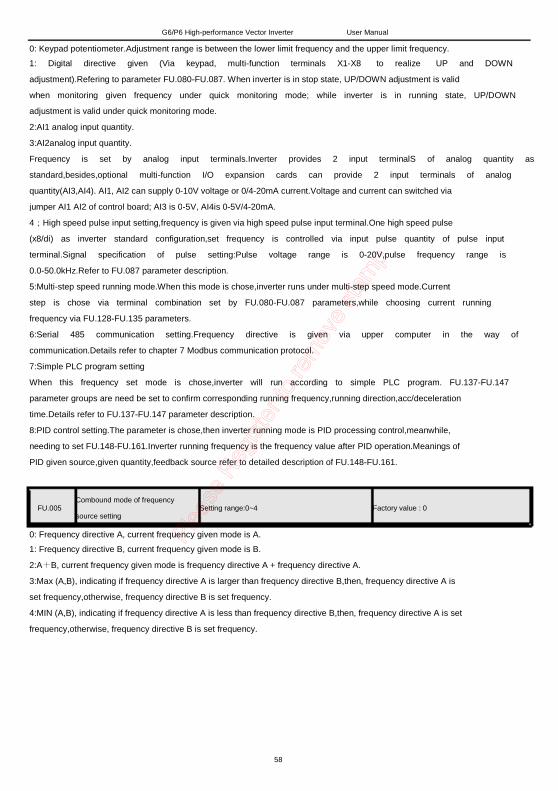
FU.005 Combound mode of frequency source setting
FU.006
FU.007
FU.008
FU.009
Gain of frequency directive A Gain of frequency directive B Frequency setting of digital keypad UP/DOWN digital given speed
2:Serial 485 communication control 0:Keypad analog potentiometer 1:Digital given (keypad,terminal UP/DOWN) 2:AI1 3:AI2 4:Pulse input 5:Multi-step speed 6:RS485 setting 7:PLC running 8:PID 0:A frequency directive 1:B frequency directive 2:A+B 3:MAX (A,B) 4:MIN (A,B) 0.10~10.00
0~8 0 03H
0~8 0 04H
0~4 0 05H
0.1~10 1.00
0.10~10.00 0.1~10 1.00
0.00~400.00Hz 0.00~600 50Hz
0.01~100Hz/S 0.01~100 1.00Hz/S
06H
07H
08H
09H
FU.010 Valid selection of UP/DOWN function key
0:Invalid 1:Valid,don't save after power off 2:Valid,save after power off
0~2 1 0AH
46
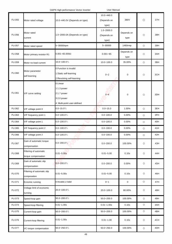
FU.011
FU.012
FU.013
FU.014
Upper limit of running frequency Lower limit of running frequency Running mode when upper limit frequency is lower than lower limit frequency Acceleration time 1
G6/P6 High-performance Vector Inverter
0.00Hz~400.00Hz
User Manual
0~400 50.00Hz
0.00Hz~400.00Hz 400~0 0.00Hz
0BH
0CH
0:Running at lower limit frequency 1:Standby (0Hz output)
0~1 0 0DH
0.1~3000.0s 0.1~3000
FU.015
FU.016 FU.017 FU.018 FU.019 FU.020 FU.021 FU.022
FU.023
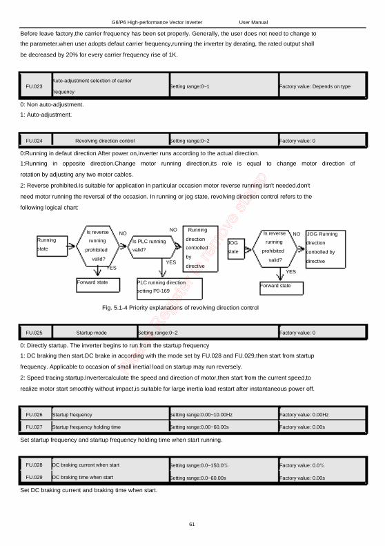
FU.024
Deceleration time 1
Acceleration time 2 Deceleration time 2 Acceleration time 3 Deceleration time 3 Acceleration time 4 Deceleration time 4 Carrier frequency Auto-adjustment selection of carrier frequency Revolving direction control
Startup frequency Startup frequency holding time DC braking current when start DC braking time when start Acc/deceleration mode selection S curve acceleration characteristic time S curve deceleration characteristic time
0:Non auto-adjustment 1:Auto-adjustment 0:Running in defaut direction 1:Running in opposite direction 2:Reverse prohibited 0:Start from startup frequency 1:DC braking then start 2:Speed tracking is valid 0.00~10.00Hz
0~1
Depends on type
Depends on type 20s 20s 20s 20s 20s 20s
Depends on type
Depends on type
0EH
0FH
10H 11H 12H 13H 14H 15H 16H
17H
0~2 0 18H
0~2 0 19H
0.00~10.00 0Hz
0.00~60.00s 0.00~60.00 0.00s
0.0~100.0% 0.0~100.0 0.00%
0.0~60.00s
0:Linear 1:S curve 0.2~2.0s
0.0~60.00s 0.00s
0~1 0
1AH
1BH
1CH
1DH
1EH
0.2~2.0 0.5s
0.2~2.0s 0.2~2.0 0.5s
1FH
20H
47
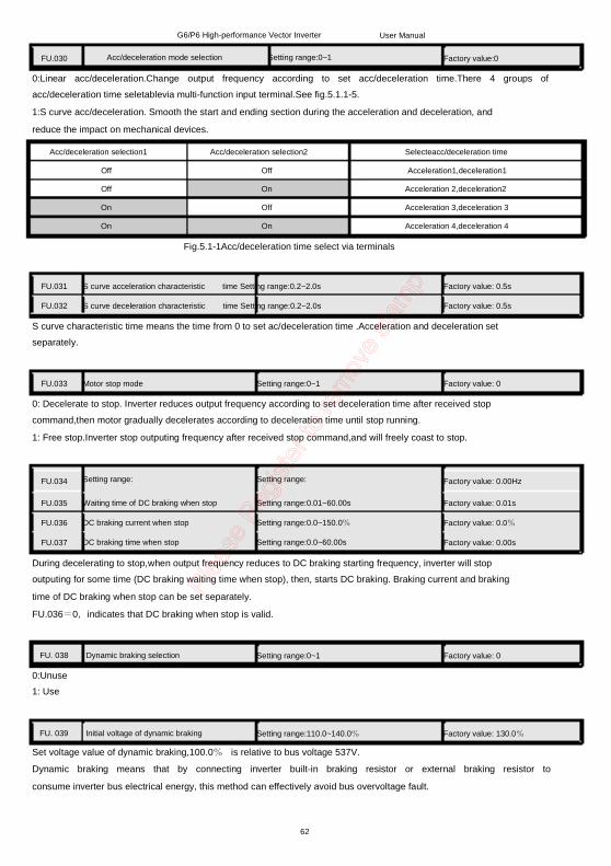
FU.033
FU.034
FU.035
FU.036
FU.037
FU.038
FU.039
FU.040
FU.041
FU.042 FU.043 FU.044 FU.045
FU.046
FU.047
FU.048
FU.049
FU.050
FU.051
FU.052
Motor stop mode
Initial frequency of DC braking when stop Waiting time of DC braking when stop DC braking current when stop DC braking time when stop Dynamic braking selection Initial voltage of dynamic braking Restart selection of instantaneous stop Restart waiting time after instantaneous stop JOG running frequency JOG acceleration time JOG deceleration time Prohibited setting frequency 1 Prohibited setting frequency 2 Width setting of prohibited frequency Dead zone betweenfarward and reverse Detection width of frequency arrival Detection value of frequency level Lagged detection value of frequency level Automatic voltage regulation output
0:Close 1:Open 2:Close when decelerating 0.4~1000.0KW
0.00~50.00 0.00Hz
31H
32H
33H
0~2 2 34H
0.4~1000.0
FU.054 Motor rated frequency 1.00~400.00Hz 1.00~400.00
Depends on type
50.00Hz
35H
36H
48
G6/P6 High-performance Vector Inverter
FU.055 Motor rated voltage 10.0~440.0V (Depends on type)
User Manual 10.0~440.0
(Depends on type)
1.0~2000.0 (Depends on
type) 5~30000
380V 37H
FU.056 Motor rated current
1.0~2000.0A (Depends on type)
FU.057 Motor rated speed 5~30000rpm
Depends on type
1460rmp Depends on
type 35.00%
38H
FU.058 Motor primary resistor R1 0.001~65.000Ω
10.0~100.0%
0:Function is invalid 1:Static self-learning 2:Revolving self-learning 0:Linear 1:1.3 power 2:1.7 power 3:2.0 power 4: Multi-point user-defined 0.0~15.0% 0.0~100.0%
0.0~100.0% 0.0~100.0%
0.0~100.0%
0.0~200.0%
0.001~65
FU.059 Motor no-load current
FU.060 Motor parameter self-learning
FU.061 V/F curve setting
FU.062 FU.063
FU.064 FU.065
FU.066
FU.067
FU.068
FU.069
FU.070
FU.071
FU.072
FU.073 FU.074
FU.075
V/F voltage point 0 V/F frequency point 1 V/F voltage point 1 V/F frequency point 2
V/F voltage point 2 Gain of automatic torque compensation Filtering of automatic torque compensation Gain of automatic slip compensation Filtering of automatic slip compesation Ecnomic running Voltage limit of economic running Speed-loop gain Speed-loop filtering Current-loop gain
10.0~100.0
39H
3AH
3BH
0~2 0 3CH
0~4 0 3DH
0.0~15.0 0.0~100.0
0.0~100.0 0.0~100.0
0.0~100.0
1.00% 0.00%
0.00% 0.00%
0.00%
3EH 3FH
40H 41H
42H
0.0~200.0 100.00%
0.01~5.00s 0.01~5.00 0.10s
0.0~200.0% 0.0~200.0 0.00%
0.01~5.00s 0.01~5.00 0.10s
0:Invalid;1;Valid
20.0~100.0%
50.0~200.0%
0.01~1.00s
50.0~200.0%
0.01~1.00s
50.0~250.0%
0~1 0
43H
44H
45H
46H
47H
20.0~100.0 80.00%
50.0~200.0 0.01~1.00s
50.0~200.0
100.00%
0.10s
100.00%
FU.076
FU.077
Current-loop filtering
VC torque compensation
0.01~1.00
50.0~250.0
0.10s
100.00%
48H
49H 4AH
4BH
4CH
4DH
49
G6/P6 High-performance Vector Inverter
gain VC slip compensation gain Filtering coefficient of multi-function terminal Function selection of programmable terminal X1/RUN
User Manual
FU.078
FU.079
FU.080
50.0~250.0% 50.0~250.0 100.00%
FU.081
Function selection of programmable terminal X2/REV
FU.082
Function selection of programmable terminal X3
FU.083
Function selection of programmable terminal X4
FU.084
Function selection of programmable terminal X5
FU.085
Function selection of programmable terminal X6/JOG
FU.086
Function selection of programmable terminal X7/RST
FU.087
Function selection of programmable terminal X8/DI
1~10
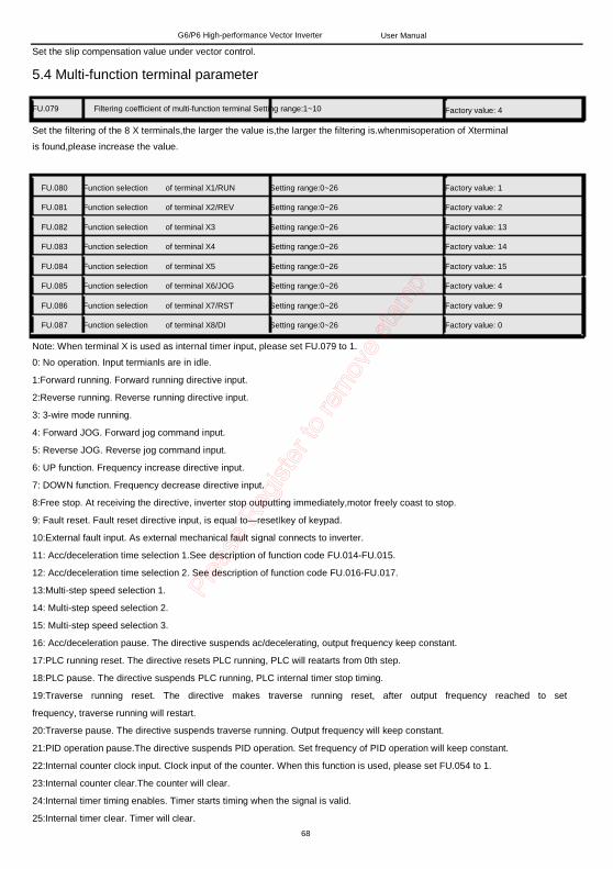
0:No operation 1:Forward running 2:Reverse running 3: 3-wire mode running 4: Forward JOG 5: Reverse JOG 6: UP 7: DOWN 8:Free stop 9:Fault reset 10:External fault 11:Acc/deceleration time selection1 12: Acc/deceleration time selection 2 13: Multi-step speed selection 1 14: Multi-step speed selection 2 15: Multi-step speed selection 3 16: Acc/deceleration pause 17:PLC reset 18:PLC pause 19:Traverse reset 20:Traverse pause 21:PID pause 22:Internal counter clock input 23:Internal counter clear 24:Internal timer timing enables. 25:Internal timer clear. 26:retain 27:frequency source switched to A frequency order 28:frequency source switched to B frequency order 29:frequency source switched to A+B frequency order 30-31:retain Note: X8 is default for pulse input by software.If is programmed as other function,pulse input is
50
1~10 4
4EH
4FH
0 50H
0 51H
0 52H
0 53H
0 54H
0~25
0 55H
0 56H
0 57H
G6/P6 High-performance Vector Inverter invalid.
User Manual
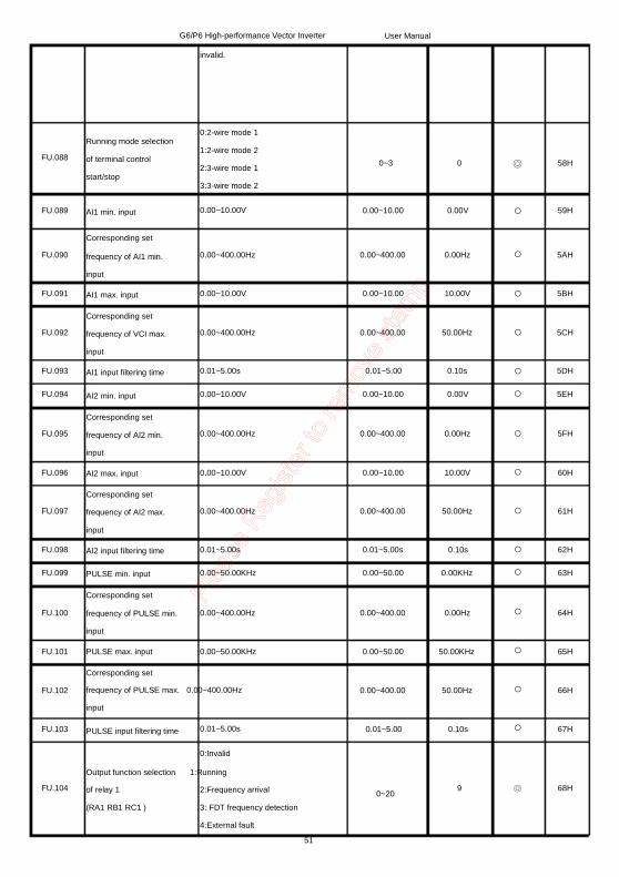
FU.088
Running mode selection of terminal control start/stop
FU.089
FU.090
FU.091
FU.092
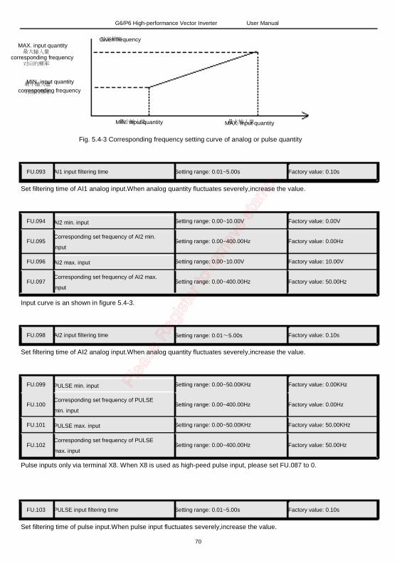
FU.093 FU.094
FU.095
FU.096
FU.097
FU.098 FU.099
FU.100
FU.101
AI1 min. input
Corresponding set frequency of AI1 min. input AI1 max. input Corresponding set frequency of VCI max. input AI1 input filtering time AI2 min. input Corresponding set frequency of AI2 min. input AI2 max. input Corresponding set frequency of AI2 max. input AI2 input filtering time PULSE min. input Corresponding set frequency of PULSE min. input PULSE max. input Corresponding set
FU.102 frequency of PULSE max. 0.00~400.00Hz input
PULSE input filtering time 0.01~5.00s
0:Invalid
0.00~400.00 50.00Hz
FU.103 0.01~5.00 0.10s
59H
5AH
5BH
5CH
5DH 5EH
5FH
60H
61H
62H 63H
64H
65H
66H
67H
Output function selection 1:Running
of relay 1 (RA1 RB1 RC1 )
2:Frequency arrival 3: FDT frequency detection 4:External fault
51
FU.104 9 0~20
68H
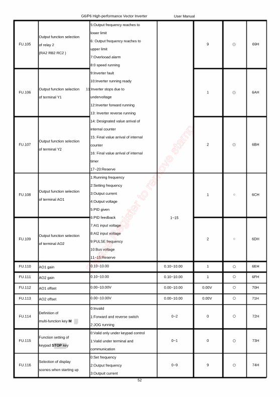
G6/P6 High-performance Vector Inverter 5:Output frequency reaches to
Output function selection of relay 2 (RA2 RB2 RC2 )
lower limit 6: Output frequency reaches to upper limit 7:Overlooad alarm 8:0 speed running 9:Inverter fault 10:Inverter running ready
User Manual
FU.105 9 69H
Output function selection 11:Inverter stops due to
of terminal Y1 FU.106 1 6AH
FU.107 Output function selection of terminal Y2
FU.108 Output function selection of terminal AO1
FU.109 Output function selection of terminal AO2
FU.110 FU.111 FU.112
FU.113
AO1 gain AO2 gain AO1 offset
AO2 offset
FU.114 Definition of multi-function key M
FU.115 Function setting of keypad STOP key
FU.116 Selection of display scenes when starting up
undervoltage 12:Inverter forward running 13: Inverter reverse running 14: Designated value arrival of internal counter 15: Final value arrival of internal counter 16: Final value arrival of internal timer 17~20:Reserve 1:Running frequency 2:Setting frequency 3:Output current 4:Output voltage 5:PID given 6:PID feedback 7:AI1 input voltage 8:AI2 input voltage 9:PULSE frequency 10:Bus voltage 11~15:Reserve 0.10~10.00 0.10~10.00
0.00~10.00V
0.00~10.00V 0:Invalid 1:Forward and reverse switch 2:JOG running 0:Valid only under keypad control 1:Valid under terminal and communication 0:Set frequency 2:Output frequency 3:Outpuit current
52
2 6BH
1 6CH
1~15
2 6DH
0.10~10.00 0.10~10.00 0.00~10.00
0.00~10.00
1
1 0.00V
0.00V
6EH 6FH 70H
71H
0~2 0 72H
0~1 0 73H
0~9 9 74H
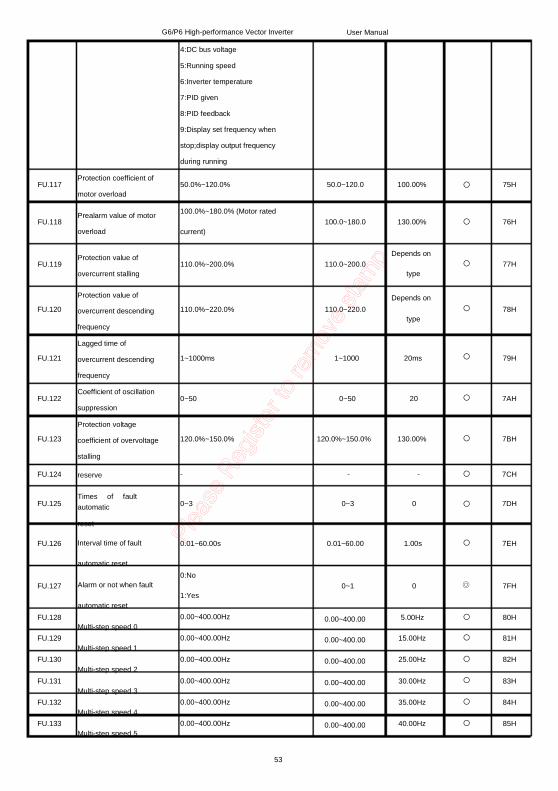
G6/P6 High-performance Vector Inverter 4:DC bus voltage 5:Running speed 6:Inverter temperature 7:PID given 8:PID feedback 9:Display set frequency when stop;display output frequency during running
Protection coefficient of motor overload Prealarm value of motor overload Protection value of overcurrent stalling Protection value of overcurrent descending frequency Lagged time of overcurrent descending frequency Coefficient of oscillation suppression Protection voltage coefficient of overvoltage stalling reserve Times of fault
automatic reset Interval time of fault automatic reset
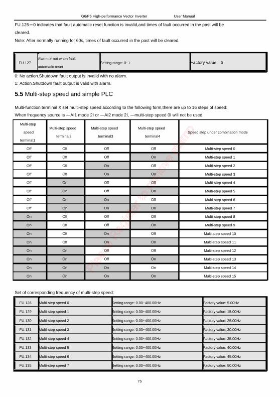
Alarm or not when fault automatic reset Multi-step speed 0
Multi-step speed 1
Multi-step speed 2
Multi-step speed 3 Multi-step speed 4
Multi-step speed 5
50.0%~120.0%
User Manual
FU.117
FU.118
FU.119
FU.120
FU.121
FU.122
FU.123
FU.124
FU.125
FU.126
FU.127
FU.128 FU.129
FU.130
FU.131 FU.132 FU.133
50.0~120.0 100.00%
75H
100.0%~180.0% (Motor rated current)
100.0~180.0 130.00% 76H
110.0%~200.0% 110.0~200.0
110.0%~220.0% 110.0~220.0
Depends on
type
Depends on
type
77H
78H
1~1000ms 1~1000 20ms
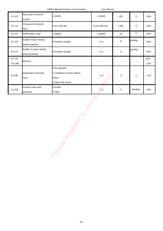
0~50 0~50 20
120.0%~150.0% 120.0%~150.0% 130.00%
- - -
0~3 0~3 0
0.01~60.00s 0.01~60.00 1.00s
0:No 1:Yes 0.00~400.00Hz
0.00~400.00Hz
0.00~400.00Hz
0.00~400.00Hz 0.00~400.00Hz
0.00~400.00Hz
0~1 0
79H
7AH
7BH
7CH
7DH
7EH
7FH
0.00~400.00 0.00~400.00
0.00~400.00
0.00~400.00 0.00~400.00 0.00~400.00
5.00Hz 15.00Hz
25.00Hz
30.00Hz 35.00Hz 40.00Hz
80H 81H
82H
83H 84H 85H
53
FU.134 FU.135
Multi-step speed 6 Multi-step speed 7
FU.136 PLC running mode
G6/P6 High-performance Vector Inverter
0.00~400.00Hz
0.00~400.00Hz
0:Single cycle 1:Keep final value after single cycle 2:Singuler cycle
User Manual 0.00~400.00 0.00~400.00
45.00Hz 50.00Hz
0~2 0
86H 87H
88H
FU.137
FU.138
FU.139
FU.140
FU.141
FU.142
FU.143
FU.144
FU.145
FU.146
FU.147
Time unit of PLC running 0th step running time of PLC 1st srteprunning time of PLC 2nd step running time of PLC 3rd step running tine of PLC 4th step running time of PLC 5th step running time of PLC 6th step running time of PLC 7th step running time of PLC Acc/deceleration time setting of PLC Running direction setting of PLC
0:second 1:hour 0~1 0
0.0~6553.5s(h) 0.0~6553.5 0.0s
0.0~6553.5 0.0~6553.5s(h) 0.0s
0.0~6553.5 0.0v6553.5s (h) 0.0s
0.0~6553.5 0.0~6553.5s (h) 0.0s
0.0~6553.5 0.0~6553.5s (h) 0.0s
0.0~6553.5 0.0~6553.5s (h) 0.0s
0.0~6553.5 0.0~6553.5s (h) 0.0s
0.0~6553.5 0.0~6553.5s (h) 0.0s
0~65535 (Binary conversion)
FU.148 PID given selection
FU.149
FU.150
PIDdigital given
Reserve
0~255 (Binary conversion)
0:Digital given 1:AI1 2:AI2 3:PULSE input 4:RS485 given 5:Keypad potentiometer 0.0~100.0%
0~65535 (Binary conversion)
0~255 (Binary conversion)
0
0
89H
8AH
8BH
8CH
8DH
8EH
8FH
90H
91H
92H
93H
0~5 0 94H
0.0~100.0 50.00%
150
95H
FU.151 Reserve 150
96H
97H
FU.152 PID feedback selection
0:AI1 1:AI2 2:PULSE input 3:Keypad potentiometer (for test
9BH 1: PID output is negative characteristic 0.00~10.00 0.00~100.00s
0.00~100.00s 0.01~10.00s
0.0~100.0%
0.01~10.00 0.0%~100.0% (Relative to set frequency) 0.0%~50.0% 0.1~3200.0s
9CH 9DH
9EH 9FH
A0H
A1H
A2H
A3H A4H
A5H
FU.166
FU.167 Data format of communication (RTU)
FU.168
FU.169
FU.170
FU.171
FU.172
RS485 communication address Answer delay Slave receive proportioncoefficient Fractional frequency of internal counter clock input Designated value of internal counter
2:9600bps 3:19200bps 4:38400bps 0:1 start bit,8 data bits,1 stop bit,nocheck 1:1 start bit,8 data bits,1 stop bit,even parity check 2:1 start bit,8 data bits,1 stop bit,odd parity check 1~247,0 are broadcast address,248 is main machine address 1~150ms
0~4 2 A6H
0~2 0 A7H
1~248 1
1~150 10ms
0.00~10.00 0.00~10.00 1
pending
A8H
A9H
AAH
1~65535 1~65535 1
1~65535 1~65535 100
ABH
ACH
55
FU.173
FU.174
FU.175
FU.176
FU.177
FU.178
~ FU.198
Final value of internal counter Timing unit of internal timer Internal timer cycle Enable of input missing phase protection Enable of output missing phase protection Reserve
G6/P6 High-performance Vector Inverter
1~65535
User Manual
1~65535 200
0.01s~655.35s 0.01s~655.35s 1.00s
1~65535 1~65535 10
0 0:Prohibit 1:Enable 0~1
pending pending
-
ADH
AEH
AFH
B0H
0:Prohibit 1:Enable 0~1 0
FU.199 Initialization of function code
FU.200 Function code write protection
-
0:No operation 1: Initialized to factory default values 2:Clear fault record 0:Invalid 1:Valid
- -
B1H
B2H~ C6H
0~2 0 C7H
0~1 0 pending C8H
56
G6/P6 High-performance Vector Inverter User Manual
Chapter 5 Description of Function Code This chapter introduces function code setting.FE,Fd function group is for inverter information inquiry.
5.1 Basic functional parameter
FU.000 Type seeting Setting range :0~1 Factory value: 0
0: G Type Suitable for heavy-duty devices (Generally for plastic packaging machinery and drawing machine).
1: P Type Suitable for heavy-duty devices (Generally forfans and water pumps).
FU.001 Speed control mode Setting range:0~1 Factory value: 0
0:Open-loop VVV/Fcontrol,VVV/Fcontrol is suitable for when high control precision is not required,as well as the
occasion that one inverter drives multiple motors.
1:Open-loop vector control, indicates without encoder,isapplicapbale to universal occasion of high-performance
without encoder,one inverter only drives one motor.such as CNC machine, centrifugal machine,lifting,extrusion
machine and so on.Before this control mode is used,please carry out FU.060 motor parameter self-learning.
Note: Function group FU.061 V/F curve parameter is also valid under vector control.
FU.002 Running directive given mode Setting range:0~2 Factory value: 0
There are up to 3 kinds of running directive given modes seletable.
0:Running directive given via operating keypad,via keys of RUN,STOP/RESET,multi-function M FU.114.
1:Running directive given via terminals, X1/RUN is for defaut forward running, X2/REV is fordefaut reverse
running,X6/JOG is for JOG,X7/RST.
2: Running directive given via serial 485communication,to achieve inverter run,stop, forward/reverse runand other
operation.Refer to Modbus communication protocol.
Note: Switch to local control (keypad control) through―running directive given modeǁ terminal.
State of running directive control terminal X1/RUN Invalid Invalid
Invalid
Invalid Valid Valid
Valid
FU.002software state setting
0
0
1
2 0
1
2
Running directive given mode in-sevice
0
0
1
2 0
0
0
Fig.5.1-1 Description of command resource switch
Running and JOG commands separately control set frequency, it will be in in running state when both of them are
valid.
FU.003 FU.004
Frequency A directive selection Setting range:0~8 Frequency directive B selection Setting range:0~8
Factory value: 0 Factory value:0
57
G6/P6 High-performance Vector Inverter User Manual
0: Keypad potentiometer.Adjustment range is between the lower limit frequency and the upper limit frequency.
1: Digital directive given (Via keypad, multi-function terminals X1-X8 to realize UP and DOWN
adjustment).Refering to parameter FU.080-FU.087. When inverter is in stop state, UP/DOWN adjustment is valid
when monitoring given frequency under quick monitoring mode; while inverter is in running state, UP/DOWN
adjustment is valid under quick monitoring mode.
2:AI1 analog input quantity.
3:AI2analog input quantity.
Frequency is set by analog input terminals.Inverter provides 2 input terminalS of analog quantity as
standard,besides,optional multi-function I/O expansion cards can provide 2 input terminals of analog
quantity(AI3,AI4). AI1, AI2 can supply 0-10V voltage or 0/4-20mA current.Voltage and current can switched via
jumper AI1 AI2 of control board; AI3 is 0-5V, AI4is 0-5V/4-20mA.
4;High speed pulse input setting,frequency is given via high speed pulse input terminal.One high speed pulse
(x8/di) as inverter standard configuration,set frequency is controlled via input pulse quantity of pulse input
terminal.Signal specification of pulse setting:Pulse voltage range is 0-20V,pulse frequency range is
0.0-50.0kHz.Refer to FU.087 parameter description.
5:Multi-step speed running mode.When this mode is chose,inverter runs under multi-step speed mode.Current
step is chose via terminal combination set by FU.080-FU.087 parameters,while choosing current running
frequency via FU.128-FU.135 parameters.
6:Serial 485 communication setting.Frequency directive is given via upper computer in the way of
communication.Details refer to chapter 7 Modbus communication protocol.
7:Simple PLC program setting
When this frequency set mode is chose,inverter will run according to simple PLC program. FU.137-FU.147
parameter groups are need be set to confirm corresponding running frequency,running direction,acc/deceleration
time.Details refer to FU.137-FU.147 parameter description.
8:PID control setting.The parameter is chose,then inverter running mode is PID processing control,meanwhile,
needing to set FU.148-FU.161.Inverter running frequency is the frequency value after PID operation.Meanings of
PID given source,given quantity,feedback source refer to detailed description of FU.148-FU.161.
FU.005 Combound mode of frequency source setting
Setting range:0~4 Factory value : 0
0: Frequency directive A, current frequency given mode is A.
1: Frequency directive B, current frequency given mode is B.
2:A+B, current frequency given mode is frequency directive A + frequency directive A.
3:Max (A,B), indicating if frequency directive A is larger than frequency directive B,then, frequency directive A is
set frequency,otherwise, frequency directive B is set frequency.
4:MIN (A,B), indicating if frequency directive A is less than frequency directive B,then, frequency directive A is set
frequency,otherwise, frequency directive B is set frequency.
58
G6/P6 High-performance Vector Inverter
Figure description of terminals:
Selection terminal AI1 of frequency directive A
Valid Invalid
Selection terminal AI2 of frequency directive B
Invalid Valid
User Manual
Frequency source in-sevice
0 1
Valid Valid
A>B B>A A<B B<A
2(A) 2(B) 3(A) 3(B)
Fig. 5.1-2Description of selection terminal of frequency source
FU.006 FU.008
Gain of frequency directive A Gain of frequency directive B
Setting range:0.10~10.00 Setting range:0.10~10.00
Factory value:1.00 Factory value:1.00
Set gain of frequency directive.0.10 means 0.1 times;10.00 means magnifying 10 times.
FU.008 Frequency setting of digital keypad Setting range:0.00~400.00Hz Factory value:50.00Hz
Set frequency value of keypad digital setting.
FU.009 UP/DOWN digital given speed Setting range:0.01~100.00Hz/S Factory value:1.00Hz/S
Set response speed of digital given value of keypad or multi-function terminal.
FU.010 0: Invalid.
Valid selection of UP/DOWN function key Setting range:0~2 Factory value:1
1:Valid,do not store after power off. After set frequency FU.008 was modified via UP/DOWN, when power
off,FU.008 will not be stored in EPP
2: Valid. After set frequency FU.008 was modified via UP/DOWN, when power off, FU.008 will be stored in EPP.
FU.011
FU.012
Upper limit of running frequency
Lower limit of running frequency
Setting range:0.00~400.00Hz
Setting range:0.00~400.00Hz
Factory value:50.00Hz
Factory value:0.00Hz
Set maximum output frequency value and minimum output frequency of inverter.
Note: Set upper and lower limit frequency is mainly to prevent misoperation of field personnel, and avoid probable
heat due to motor running frequency too low, or machinery wear caused due to running frequency is too high.
FU.013 Running mode when upper limit frequency is lower than lower limit frequency
Setting range:0~1 Factory value:1
The function is for running state when set frequency is lower than lower limit frequency, validwhen the lower
frequency is higher than 0.
0:Run at lower limit frequency.
1:Standby,when set frequency is lower than lower limit frequency,inverter free stop;Whensetfrequency is large or
equal to upper limit frequency again,inverter will run automatically.
59
G6/P6 High-performance Vector Inverter User Manual
FU.014 Acceleration time 1 Setting range:0.1~3000.0s
FU.015
FU.016 FU.017 FU.018 FU.019 FU.020 FU.021
Deceleration time 1
Acceleration time 2 Deceleration time 2 Acceleration time 3 Deceleration time 3 Acceleration time 4 Deceleration time 4
Function selection of terminal X1/RUN Function selection of terminal X2/REV Function selection of terminal X3 Function selection of terminal X4 Function selection of terminal X5 Function selection of terminal X6/JOG Function selection of terminal X7/RST Function selection of terminal X8/DI
0th step running time of PLC 1st srtep running time of PLC 2nd step running time of PLC 3rd step running tine of PLC 4th step running time of PLC 5th step running time of PLC 6th step running time of PLC 7th step running time of PLC 8th step running time of PLC 9th srtep running time of PLC 10th step running time of PLC 11th step running tine of PLC 12th step running time of PLC 13th step running time of PLC
After internal counter clock input received signal,should go through internal fractional frequency operation ,then is
accumulated to internal counter.
For example: When the parameter is set to 100, after 100 pulses were received, the internal counter count
accumulates 1.
FU.172
FU.173
Designated value of internal counter Final value of internal counter
Setting range:1~65535
Setting range:1~65535
Factory value: 100
Factory value: 200
Combined with output terminals to use.When counting value is larger than designated value,output terminals will
output internal counter designated value arrival signal. When counting value is equel to final value, output
terminals will output internal counter final value arrival signal.
Note: Clear counter by using terminal function of ―internal counter clearǁ
For example: When FU.171 is set to 2, FU.172 is set to 5, FU.173 is set to 9,counting and signal diagram is shown
below.
Counter clock input 计数器时钟输入
Counter counting value 计数器计数值
Counter final计数器终值到达 value arrival
0 1 2 3 4 5 6 7 8 9 0 1 2 3
Valid signal
有效信号 Valid signal
Fig. 5.9-1 Counter, timer
Setting range:0.01s~655.35s Setting range:1~65535
有效信号
Counter designated value arrival
计数器指定值到达
FU.174 FU.175
Timing unit of internal timer Internal timer cycle
Factory value: 1.00s
Factory value: 10
Combined with output terminals to use.When internal timer arrives to timing cycle,output terminals will output
internal timer cycle arrival signal. The timer's time cycle is the product of parameter FU.174 and parameter
FU.175.
Note: Internal timer starts timing only by using terminal function of ―internal timer timing enablesǁ.Clear timer by
using terminal function of ―internal timer clearǁ.Clear counter by using terminal function of ―internal counter clearǁ .
81
G6/P6 High-performance Vector Inverter User Manual
For example: When FU.174 is set to 0.1s, FU.175 is set to 5,time cycle of timer is 0.1s ×5=0.5s.Timing and signal
diagram is shown below.
Timer timing enable signal
定时器计时使能信号
Timer timing
value arrival 定时器计时值
Timer cycle arrival
定时器周期到达
有效信号
Fig. 5.9-2 Timing function diagram
5.10 Missing phase protectionof input and output
Valid signal
FU.176 Enable of input missing phase protection
Setting range:0~1
0
有效信号
0.0 0.1 0.2 0.3 0.4 0.5 0.0 0.1 0.2 0.3
Valid signal
Factory value:
0: Prohibited
1: Enable
FU.176 Enable of output missing phase protection
Setting range:0~1 Factory value:
0: Prohibited
1: Enable
FU.176 FU.198
Reserve
5.11Password protection and initialization parameter
FU.199 Initialization of function code Setting range:0~2 Factory value: 0
0: No operation.
1:Initialized to factory defaut value. Function group restore to factory state.2: Clear fault record.
FU.200 Function code write protection
Setting range:0~1 Factory value: 0
0:Invalid.Function group FU can be changed.
1: Valid. Function group cannot be changed.
82
FE.OOO FE.OO1 FE.OO2
FE.OO3 FE.OO4
FE.OO5
FE.OO6 FE.OO7
FE.OO8
FE.OO9
FE.O10 FE.O11
FE.O12
FE.O13 FE.O14
G6/P6 High-performance Vector Inverter
FE Fault factors
current fault type
current fault type output frequency
current fault type output current
current fault type busbar voltage
current fault type move direction
last fault type
last fault type output frequency
last fault type output current
last fault type busbar voltage
last fault type move direction
The first two fault type
The first two fault type output frequency
The first two fault type output current
The first two fault type busbar voltage
The first two fault type move direction
User Manual
0(No Fault)~18
0.00~400.00Hz 0.00~2000.0A
0.00~1000V
0(No Fault)~18
0.00~400.00Hz 0.00~2000.0A
0.00~1000V
0(No Fault)~18
0.00~400.00Hz 0.00~2000.0A
0.00~1000V
DDH DEH DFH
EOH E1H
E2H
E3H E4H
E5H
E6H
E7H E8H
E9H
EAH EBH
FD human-computer interface display factor
frequency setting
input frequency
input current
input voltage
current voltage
operating speed
frequency inverter temperature
PID
PID Feedback
input pulse frequency
VIC input voltage
CCI input voltage
input terminal status
AO1 output voltage
AO2 output voltage
output terminal status
0.00~400.00Hz
0.00~400.00Hz 0.1~2000.0A 0.1~2000.0V
100~1000V
0~30000rmp
0~100 celsius degree 0.00~10.00V
0.00~10.00V
0.01~50.00KHz 0.00~10.00V
0.00~10.00V
Fd.000 Fd.001 Fd.002 Fd.003
Fd.004
Fd.005
Fd.006 Fd.007
Fd.008
Fd.009 Fd.010
Fd.011
Fd.012 Fd.013 Fd.014
Fd.015
0.00~10.00V
0.00~10.00V
ECH EDH EEH EFH
FOH
F1H
F2H F3H
F4H
F5H F6H
F7H
F8H F9H FAH
FBH
83
Fd.016 Fd.017
Fd.018
Fd.019 Fd.020
G6/P6 High-performance Vector Inverter
accumulated running hours
software edition No.
Retain
Retain
Retain
User Manual 0~65535h FCH
FDH
FEH
FFH 100H
84
G6/P6 High-performance Vector Inverter User Manual
Chapter 6 Fault Alarm and Countermeasures 6.1 Fault and Alarm Fault and alarm are both abnormal states. But there is obvious difference between them. Inverter self-monitors during running. If fault occurs, inverter will display fault code, and cut off inverter output to make motor in free running state and stop revolving; while if alarm occurs,inverter will display alarm code, inverter do not cut off output under alarm state, motor is still controlled by inverter. 6.1.1 Fault indication and fault reset 1~15 are for fault indication. There are a number of ways of inverter fault reset: keyboard "reset button", terminal reset function, or, if necessary, fault reset can also be achieved by turning off the main power supply for some time. If fault has disappeared, inverter will resume normal operations; otherwise inverter will trip again. Note: If start command is valid, fault reset will start transmission equipment. 6.2 Fault alarm and contermeasures
Fault Code
No. English Abbr.
Type Fault causes Countermeasures
Ac/deceleration time is too short. Prolong ac/deceleration time.
Inverter power is too small. Grid voltage is too low Ac/deceleration time is too short. Output side of inverter is short. Power module is damaged. External interference. Deceleration time is too short,
Choose one level bigger inverter Check input voltage. Prolong ac/deceleration time. Check motor insulation. Seek for support. Check whether peripherals are with strong interference source. Prolong deceleration time.
1 oc Overcurrent fault
2 Sc Power module fault
3 ou Bus overvoltage fault
regeneration energy is too large. Check input voltage.
Grid voltage is too high. Choose one level bigger inverter.
85
G6/P6 High-performance Vector Inverter User Manual
4 Lu Bus undervoltage
fault
Load inertia is too large,
regeneration energy is too large.
Grid voltage is too low.
Grid voltage is too low.
Load inertia is too large.
5 oL Motor overload fault Motor rated current setting
wrong.
Inverter power is too small.
Check input voltage.
Check input voltage.
Check load, adjust torque boost
quantity.
Reset motor rated current.
Choose one level bigger inverter.
Ambient temperature is too high. Check whether ambient
Poor ventilation of inverter.
Cooling fan fault.
Temperature inspection circuit
fault. Soft start circuit or contactor is
damaged.
3-phase AC input missing phase.
Current of 3-phase input side is
asymmetric. External fault signal input
temperature meets requirement.
Improve ventilation.
Check whether cooling fan run.
Seek for support.
Seek for support.
Check input power supply and the
cable. Check output cable and motor
insulation.
6 oH Inverter overheating
fault
7 cno
8 ILP
9 OLP
Soft start fault Input missing phase
fault Output missing
phase fault
External equipment terminal acting.
fault 10 EF
11 tA
12 cdE
Lifetime arrival fault. Current detecting
circuit fault.
13 EEP EEPROM read-write
fault
―STOPǁ key of keypad is set to
emergency stop. Lifetime set by manufacturer
arrival. Current detecting component
damaged.
Control panel component
damaged.
External interference.
Check external fault cause.
Check keypad ―stopǁ key setting.
Contact manufacturer
Seek for support.
Seek for support.
Check if peripherals are with
strong interference source.
Deviation between test results Confirm motor is under no load
14 AUE Motor parameter
inspection fault and theoretical value is too large. state.
Motor parameter set wrong Check motor parameter
setting.
86
G6/P6 High-performance Vector Inverter User Manual
12 EIF CPU disturbed fault External interference. Check if peripherals are with strong interference source.
6.3 Solutions of common fault Inverter may encounter several of the following failure in use, please follow the steps as below to do simple fault analysis: 6.3.1 No display after power on 1. With a multimeter check whether the input power source of inverter is consistent with the rated voltage of inverter. 2. Check inverter bus voltage with a multimeter, determine whether three-phase rectifier is good. 3.Check if the ―CHARGEǁ light is lit. 4. If the above are OK, fault may exist in switching power supply section. Please seek service. 6.3.2 Motor does not run after inverter ran 1. For motors with band-type brake, please make sure that the motor is not in band-type braking state. 2. Disconnecting inverter and motor, runninginverter at 50Hz, and with a multimeter, check whether there is balanced voltage among three-phase output u, v, w. Note that since that among u, v, w arehigh frequency pulses,analog voltage meter(range: AC 500V) should be used. If voltage is unbalanced or there is no voltage, the inverter module is damaged.Please seek service. 3. If the above are OK, please seek service 09327444043 / 09824692665.
87
G6/P6 High-performance Vector Inverter User Manual
Chapter 7 Serial 485 (MODBUS) Communication Protocol The inverter supports Modbus protocol, RTU format, Broadcast address 0, master address 248, slave address ―1-247ǁ.
7.1 Composition of MODBUS communication 7.1.1 Interface mode RS485: asynchronous, half duplex, LSB sending priority. Low byte is after the high byte. Inverter communication port: terminal RS485+/-, default data format: 8-N-1, 9600 bps.
485 communication
converter/PC
Fig.7.1.1-1 Wiring of 485 interface
7.1.2 Communication network mode
MODBUS communication is composed by 1 master station and up to 31 slave
stations at most,andtakes the form of master station sending directives and slave station
responding. Each time master station takes serial communication with one slave station.
Therefore, assign address number in advance for each station, main station directives
conduct signal communicates in accordance with the number. After Received instruction
from main station, slave station performs assigned functions, to respond to the main
station.
The following intervals must be kept between the messages:
88
G6/P6 High-performance Vector Inverter User Manual
Fig. 7.1.2-1 Serial communication
7.2 Message Format MODBUS communication takes the form of master station sending directives and slave station
responding. Massage format of sending and receive is composed as shown in fig. 7.2-1,data
length changes along with different directive (function) contents.
Slave station address Function code
Data Error inspection
Fig. 7.2-1 Serial communication message format
1. Slave station address
Inverter address range is (0~C7Hex).If it is set to 0, master station sends to all the slave
stations, but slave stations do not respond.
2. Function code
Function
(Hex) 03H 08H
10H
Directive message Response message
Mini.(byte) Max.(byte) Mini.(byte) Max.(byte)
8 8
11
8 8
41
7 8
8
37 8
8
80H
Function
Read the contents of register Loopback test Multiple memory registers
write in Slave register receive data
error 5 5
Fig. 7.2-2serial communication function code explanation
3. Data
89
G6/P6 High-performance Vector Inverter User Manual
Memory register number (test code when number) and its datenverbund constitute a series of
data. Data length changes according to the directive content. 4. Error detection
CRC-16 (CRC: Cyclic Redundancy Check, checksum method) is used to check out errors in
communication. Check and operation results are saved in a data (16 bits), the start value is FFFFH.
Put the data packet that is to be sent (slave station address, function code and data) and fixed
value A001H together to conduct oxr and shift operation. After the operation is finished,
checksum value is included in the data.
Check and operation proceed in accordance with the following methods:
1) Start value of the 16-bit data used for operation must be set to start FFFFH.
2) Must conduct xor operation by using start value and slave station address.
3) Must right shift the result until the overflow bit turn out to be 1.
4) When the overflow bit turns out to be 1, must conduct oxr operation by the third step
result and fixed value A001H.
5) After 8 times shift operations (whenever the overflow bit becomes 1, it must, as
described in step 4 carry on oxr operation), carry on oxropereation with the last operation
result and the next data packet (8-Bit function code) . The result must execute 8 times shift
operations again, when the overflow bit becomes 1, needs to carry out oxr operation with the
fixed value A001H.
6) To process the data in the same procedure. The high byte is processed first, and then
the low byte, until all of the data processing is completed.
7) The operation result is checksum, consisting of a high byte and a low byte.
Note: When add checksum into data frame, add low byte first, then add the high byte.
7.3 MODBUS massege example
7.3.1 Read register contents
At most 16 inverters'momery register contents can be read each time. Firstly,the directive message must contain the start address of the first register to read and the
quantity of the registers to read.Response message will contain the contents of the registers to
read.The contents of memory register is divided into the high 8 bits and the low 8
bits,becoming data of response massege in numerical order.
Read message from 000H, 001H registers of slave inverter 2, which is shown as below.
90
G6/P6 High-performance Vector Inverter User Manual
Directive massage Slave station address Founction code
Start address High order Low order
02H 03H 00H 00H
quantity
CRC-16
High order Low order High order Low order
00H 02H C4H 38H
Response massege (normal state) Slave station address Function code
Test code
Data
CRC-16
High order Low order High order Low order High order Low order
02H 08H 01H 02H 03H 04H 41H 37H
Response massege (fault state) Slave station address Function code Error code
CRC-16 High order Low order
02H 80H F1H C1H 03H
Fig. 7.3.1-1 Serial communicationread command example
91
G6/P6 High-performance Vector Inverter User Manual
7.3.2 Loop test Directive message returned directly as a response message, using communication detection between master and slave stations. Any calue can be used for test code and data.
Loop test message of the slave inverter 2 is demonstrated as follows. Directive massege
Slave station address Function code
Test code
Data
CRC-16
High order Low order High order Low order High order Low order
02H 08H 01H 02H 03H 04H 41H 37H
Response massege (normal state) Slave station address Function code
Test code
Data
CRC-16
High order Low order High order Low order High order Low order
02H 08H 01H 02H 03H 04H 41H 37H
Response massege (fault state) Slave station address Function code Error code
CRC-16 High order Low order
02H 80H 03H F1H C1H
Fig. 7.3.2-1 Serial communication loop test example
92
G6/P6 High-performance Vector Inverter User Manual
7.3.3 Write in of multiple memory registers At most 16 inverter memory registers can be writedin.Begin with the assigned number, write the assigned data into assigned quantity of memory registers.Write in data must conduct in
accordance with numbered order of the Registers, respectively, in order of high 8 bits and low
8 bits aligned in directive message.
From PLC modify 000H, 001H registers' messages of slave inverter,which is shown as follows: directive mesage
Slave station address Function code
Start address
quantity
High order Low order High order Low order
The number of data
Start data
The next data
CRC-16
High order Low order High order Low order High order Low order
Response massege (normal state) Slave station address Function code Start address
Quantity
CRC-16
High order Low order High order Low order High order Low order
02H 10H 00H 00H 00H 02H 51H 9FH
93
G6/P6 High-performance Vector Inverter User Manual
Response massege (fault state) Slave station address Function code Error code CRC-16 High order
Low order
02H 80H 01H 31H C2H
Fig. 7.3.3-1 Example of serial communication write in
Read contents. MODBUS register address of each function code refers to function code list.
The data is transmitted as an integer, pay attention to the units of the function code. 7.3.4 Data save directive When MODBUS communication is used, if write function code data in inverter from PLC,
function code data will be saved in inverter internal data fields temporarily.
The function code data of the RAM is written to inverter internal EEPROM (permanent storage)
by the save directive.Write 1 in 0909H register,thenData save directive can be carried on by
writing 1 into 0909H register. 7.3.5 Broadcast sending data When send data by broadcast, one directive can be sent simultaneously to all slave stations.
Slave station address of directive message must be set to 00H. All slave stations receive the
information, without response.
7.4 Slave inverter
When inverter address is 1~31,the slave station will receive the following data. 7.4.1 Directive data Directive data is shown as below.Write in only by function code 00H. MODBUS
G6/P6 High-performance Vector Inverter User Manual
902H 903H~908H 909H
PID given value Retained Save directive 1: save parameter to EEPROM
Note:Bit 0 is the lowest order bit
Fig. 7.4.1-1 Data defination of serial communication directive
7.4.2 Monitoring data
Function code of function group d0、d1、d2、d3 can act as monitoring data by using function
code 003H.
7.4.3 Setting data
Function code of function group P0 can be modified, writing in by function code 10H. MODBUS
register address of each function group refers to function group list. The data is transmitted as
an integer, pay attention to the units of each function code.
7.4.4 Testing data
Receive test data of function code 08H during loop test, and respond. 7.5 Master Inverter When inverter address is 32, the inverter acts as a master inverter and sends the following
broadcast data. At this time master inverter sends running and stop directive according
to
current operating state, the set frequency is sent as a frequency directive. MODBUS register
address is 900H and 901H.
Master inverter sends frequency directive 50.0Hz and set forward running message, which is
shown as below: MODBUS
Register address
contents
900H
901H
Bit 0 Bit 1 Bit 2 Bit 3~F Frequency directive
Running directive 1:running,0:stop
Direction directive 1:reverse running,0:forward running Retained Retained
Note: Bit 0 is the lowest order bit
95
G6/P6 High-performance Vector Inverter User Manual
Directive message Slave station address Function code
Start addree
Quantity
High order Low order High order Low order
The number of data
Start data
The next data
CRC-16
Fig. 7.5-1 Serial command example when inverter is master station
7.6 MODBUS communication error code
When slave inverter receives error data, will answer data fram of function code 80H, error code
is shown as below:
Error code 01H 02H
High order Low order High order Low order High order Low order
Contents Do not allowed to write in the data during running Data overflow
1. MODBUS address out of range.
2. Number of data out of range.
3. When writing data, the data contents exceed the upper and lower limits. Function code overflow
Fig. 7.6-1 serial communication error code
7.7 No Response Fault Inspection of Slave Machine Under the following condition, salve station ignore directive message of master station, does not sent response message. 1. Transmission error is checked out in directive message (over adjustment, framing, parity, CRC-16)
96
G6/P6 High-performance Vector Inverter User Manual
2. Slave address in directive message is not accordance with the slave address of inverter
side.
3. When time interval between data and data that constitutes message exceeds 24 bits.
97
G6/P6 High-performance Vector Inverter User Manual
Chapter 8 Repair and Maintenance 8.1 Periodic Inspection As a result of inverter use environment changes, such as temperature, humidity, smog and so on, as well as aging of inverter internal parts, kinds of faults may occur. Therefore, in the course of storage and use, daily inspection and periodic maintenance should be carried on.
Inspection Items Terminal screws
Heatsink
PCB(printed circuit board) Cooling fan
Inspection contents Whether the screws are loosen
Whether there is dust
Power component
Bus aluminum electrolytic capacitor
Whether there is dust
Whether there is abnormal noise, abnormal vibration. Whether there is dust Is there color change, strange smell, bubble or leak.
Solutions Screw up by screwdriver. Blow the dust off with 4~6kg/cm 2dried compressed air Blow the dust off with 4~6kg/cm 2dried compressed air. Replace the cooling fan. Blow the dust off with 4~6kg/cm 2driedcompressed air.
Replace aluminum electrolytic capacitor.
Fig. 8.1-1 Inverter periodic inspection
8.2 Components replacement agelimit
Fansand bus aluminum electrolytic capacitors are easy to damage parts of inverter, to ensure
long-term security work of inverter, please replace periodically. Under condition of ambient
temperature below 30, 80% rated load, running time of 12 hours/day, replacement time is as
follows:
1. Fan: should be replaced after 3 years.
2. Aluminum electrolytic capacitor:should be replaced after 5 years.
8.3 Warranty Description
Calculating from the date of leaving factory, the warranty period is 18 months. Manufacturer is
responsible only for quality issues due to improperdesign and productive process, not for the
damage caused by transport or unpacking. Regarding incorrect installation and use, such as
temperature, dust, corrosion, which do not comply with the prescribed working conditions, as
well as damage caused by overload running, manufacturer is irresponsible.