11
UW - Madison Thermal Hydraulics Laboratory Facilities Mark Anderson UNIVERSITY OF WISCONSIN 1

UW-Madison Thermal Hydraulics Laboratory Facilities
Mark Anderson
UNIVERSITY OF WISCONSIN 1

• 4 rod bundles capability at 100kW/rod• 400 KW cooling capacity• Option of visualization of low pressure flows• High speed video of CHF and flow oscillations at low pressures• Pressures from ambient to 3600psi• Mass flux up to 3000 kg/m2S• Fluid temps to 550 C• Pressures up to 3600 psi (25MPa)• Can run supercritical water heat transfer conditions with a four rod simulated reactor bundle. • Able to run cosine profile and uniform profile heat flux from simulated fuel pins • 2 meter heated length – 3 meter overall test section height. • Secondary side can also run low pressure transparent CHF and heat transfer up to 9 MW/m2 heat flux
Heat transfer and CHF test facility
2
TEST CONDITIONSPressure: Atm – 25 Mpa (3600 psi)Temperature: 25 – 650°C Mass Flux: 500 – 1500 kg/m2s
Visualization of boiling and CHF

Operation to 650CIn house designed and constructed EM pump (current project to optimize EM pump end effects)Full diagnostic loop to control and measure O2 concentration (cold trap, plugging meter, vanadium wire)Used to study materials, thermal striping and thermal stratificationFacility equipped with sodium scrubber and fire protectionUp to 300 gallons of sodium flow loop testing capability
Sodium testing facilities (SFR’s)
3
• 1 inch diameter flow loop• 10 m/s flow in test section – 14 GPM at 15 psi head• Able to run 12 flat samples and 10 stressed C-samples• O2 control (cold trap) with a plugging O2 sensor (20ppm)• EM - flow meter calibrated against high temp vortex• 650 C operation temp ~ 1 gallon total Na inventory

4
Air and water RCCS facilities (HTR)
¼ scale water cooled system30kW of heat input2 phase flow sensors Ability to do tank depletion tests, RCCS heat removal and fundamental multiphase flow heat transfer
¼ scale air cooled systemHoused in a 24 foot dia x 40ft tall concrete silo with control room in adjacent laboratory. 30kW heater input power5 ton overhead crane to allow modification to the facility
42 ft (13m)
Two concrete experimental silos with a 24 foot diameter 40 feet tall and up to 1MW electrical power

UW Flibe natural convection loop
Glassy carbon –counterMoly – Working/quasi-reference
• High spatial resolution distributed fiber temperature measurements• Online redox measurement• Corrosion and TH testing
• 1 inch tube • 10 kW of input power• Flows on the order of 0.1 m/s

On going work:
LWR – bundle test loop• CHF tests from 18-22 Mpa• Bundle heat transfer tests in SCWR 25MPa• Bundle heat transfer with sCO2 • CHF of accident tolerant fuel.RCCS (Air and water):• Some two-phase flow stability experiments with high fidelity diagnosticsSodium loops:• Thermal stripping and thermal stratification testing• EM-pump testing with (ALIP and moving magnet)Flibe NC loop• Thermal hydraulic testing• Material testing• Redox control.
Flibe purification facility Other salt flow loops – nitrate salt testingsCO2 test facilities (PCHE testing)Nuclear reactor – instrumentation testing
Access facility: [email protected]
6UNIVERSITY OF WISCONSIN

AlF3 BaF2 CaF2 CrF2 MgF2 MnF2 NiF2 KF NaF SrF4 TiF4 0
100
200
300
400
500
Part
s Per
Mill
ion
FLiBe/ fluoride/chloride Purification facility
Corrosion Products (less stable)
Salt Constituents (more stable)
HF Cylinder PurificationVessel
Wisconsin fluoride-salt purification
Impurity removal: Hydrofluorination purification
Receiving Vessel
Off-GasMonitoring
Purified FLiBe salt composition
Inductively coupled plasma – optical emission spectroscopy (ICP-OES)
66 ± 3 mol. % LiF33 ± 1 mol. % BeF20.14 ± 0.01 mol. % Impurity Metals
B. C. Kelleher, “Purification and Chemical Control of Molten Li2BeF 4 for a Fluoride Salt Cooled Reactor,” Ph.D., The University of Wisconsin - Madison, United States -- Wisconsin, 2015.
Flibe purification system
• Capable of HF/H2 purification with Be reduction of up to 70kg of salt at a time• Salt chemical and redox analysis

sCO2 HX and Regenerator test facility
8
CSM – GPROMs model
• Up to 550 C and 3000 psi• Flows up to • Measure effectiveness, thermal stress, components
Header weldsBefore welding
diffusion bond piece
solid pieces
heat affected zone in
diffusion bond
Etch-mask penetration defects
Bond inclusions in alloy 617 [1]
1 mm

In Core reactor instrumentation testing
UNIVERSITY OF WISCONSIN 9
Underwater housing for testing instrumentation • Temperatures to 1200 C• Neutron flux to 1013 n/cm2
• Multiple ports for testing up to ½ probes• Fast ramp and cool down rates.
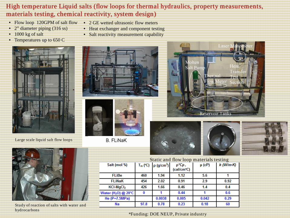
High temperature Liquid salts (flow loops for thermal hydraulics, property measurements, materials testing, chemical reactivity, system design)
Study of reaction of salts with water and hydrocarbons
Static and flow loop materials testing
Large scale liquid salt flow loops
*Funding: DOE NEUP, Private industry
• Flow loop 120GPM of salt flow • 2” diameter piping (316 ss) • 1000 kg of salt • Temperatures up to 650 C
• 2 GE wetted ultrasonic flow meters• Heat exchanger and component testing• Salt reactivity measurement capability

Thermal Striping ability to use distributed optical fibers
11
• Test section promotes thermal striping with two jets of sodium at different temperatures impinging upon one another at a 90 degree angle.
• 3 optical fibers installed concentric to each tube of the junction as seen in figure. 5mm spatial temperature resolution


