94
V-30/40 ɊɍɄɈȼɈȾɋɌȼɈ ɉɈɅɖɁɈȼȺɌȿɅə ȼȿɊɋɂə: IM-V051800 ʋ: P20ABEV34A
V-30/40
VER:IM-V051800NO:P20ABEV34A
: IM-V051800 : P20ABEV34A

CONTENT PAGES
PREFACE, INTRODUCTION, COPYRIGHT
1. SAFETY PRECAUTIONS
2. MACHINE FEATURE
3. TRANSPORTATION
4. INSTALLATION
5. KEY PARTS FEATURES
5-1 PNEUMATIC SYSTEM
5-2 COOLANT SYSTEM
, , ................................................................................ I, II, III 1. 1-1 ....................................................................................................... 1-1 1-2 ............................................................................... 1-3 1-3 ........................................................ 1-5 1-4 ............................................................................................................................................... 1-9 2. 2-1 ….. ....................................................................................................................................... 2-1 2-2 ……………………………………………......................................... 2-3 2-3 ............................................................................................................ 2-7 3. 3-1 ....................................................................................................................... 3-1 3-2 …............................................ 3-2 3-3 ................................................................................................ 3-4 4. 4-1 ....................................................................................................................... 4-1 4-2 ........................................................................... 4-1 4-3 .................................................................................................................................... 4-3
5. 5-1 ................................................................................................................. 5-1 5-1-1 …..…………………................................................................................ 5-1 5-1-2 ..................................................... 5-2 5-1-3 ...................................................................... 5-3 5-1-4 ...........................…..................................................... 5-4 5-1-5 ...........................…..................................................... 5-5 5-2 ........................................................................................................................... 5-7 5-2-1 ................................................................................... 5-7 5-2-2 ......................................................................................................... 5-7 5-2-3 ........................................................................................ 5-7 5-2-4 ............................................................................................................................................... 5-7 5-2-5 ........................................................................................... 5-8 5-2-6 …………............................................................................................................................... 5-8 5-2-7 ........................................................................ 5-8

5-3 SPINDLE OIL COOLER SYSTEM
5-4 LUBRICATION SYSTEM
5-5 HEAT EXCHANGER SYSTEM
6 OPERATION
7 CLEAN AND MAINTENANCE
5-3 ....................……................................................... 5-9 5-3-1 …........................................................................................................................... 5-9 5-3-2 …………................................................................................................................................... 5-9 5-3-3 ..................................................................................................................... 5-10 5-3-4 ........................................................................................... 5-10 5-3-5 ............................................................................................................ 5-11 5-3-6 ....................................................................... 5-12 5-4 …………....................................................................................................................... 5-13 5-4-1 …............................................................................................................................ 5-13 5-4-2 ...................................................................................... 5-13 5-4-3 ………………………….......................................................... 5-16 5-4-4 …………………………........................................................... 5-17 5-5 ………………………………………………….......................................... 5-17 5-5-1 …………………………............................................ 5-17 5-5-2 ……………………………………………..........................................… 5-17 5-5-3 …………...........................................…. 5-17 5-5-4 ………………………………………...........................................… 5-18
6 6-1 (M / M ) ................................................................................... 6-1 6-2 (S /S ) ..........….................................................. 6-1 6-3 (T /T ) .............................................................................. 6-1 6-4 (F ) .................................................................................... 6-1 6-5 (G ) .................................................................................................... 6-2 6-6 ....................................................................................................................................................... 6-2 6-7 ................................................................................................................................... 6-3 6-8 (MDI)…............................................................ 6-5 6-9 (MDI)............................................................... 6-7 6-10 ............................................................................................. 6-9 6-11 ..................................................................................................................…................................. 6-16 7. 7-1 ..................................................................................... 7-1 7-2 ................................................................................ 7-2 7-3 , ................................................... 7-2 7-4 ........................................................................................ 7-3 7-5 .......................................................................... 7-3 7-6 ............................................................................................................................. 7-3 7-7 .................................................................................................................................. 7-4 【 】I - M II - G III - : .

- I -
PREFACE
Leadwell dealer local agent
. Leadwell ,
. ,
(V-40) , . -
, Leadwell.

- II -
BRIEF INTRODUCTION OF LEADWELL LEADWELL
Leadwell CNC Machines Mfg., Corp., 1980 , .
Leadwell , .
Leadwell , ,
, ( ), , , 5- ,
( ). 1993 Leadwell -
, ISO 9001. , Leadwell .
1997 Leadwell , . , ,
. 1999 : Leadwell CNS 14001
.
Leadwell « - »;
, .
, 1 .
- III -
CHANGES AND COPYING
Leadwell ,
.
Leadwell. Copyright 2005 Leadwell CNC Machine Mfg., Corp. .

1-1
1 SAFETY PRECAUTIONS
1-1 SAFETY RULES However, safe operation cannot be ensured if operators use a CNC Machine Center improperly or do not follow safety rules properly. Failure to comply with these rules may result in death, injury, or damage to the machine and/or products. In addition to the safety information in this manual, common sense tells us there are many "Don'ts" when operating a machine. Unless an operation is specifically stated in this instruction manual, consider that operation a "Don't".
1-1-1 The basic conditions given below must always be strictly followed.
1.
, , . .
, . . ,
.
1-1
, .
, / .
, , , « »,
. : , , « » , « ».
1-1-1 .
.
, ,
. .
, ,
, , .
, (
), , . .
.
, .
, , .
, ,
, .
,
.

1-2
, .
.
, . . , .
, - ,
. , - , ,
.
, . , , .
, , ,
, .
1-3
1-2 GENERAL SAFETY INSTRUCTIONS 1-2-1 CAUTIONS OF OPERATING MACHINE:
emergency stop
1-2
1-2-1
.
, , . .
, ,
.
, .
,
.
, , , .
.
,
.
, .
, .
.
,
.
, .
, , , ,
. , .
. .
,
. . , .

1-4
1-2-2 ROUTINE INSPECTIONS:
1-2-3 WARM UP AND PREPARATION:
1-2-2
.
, .
, , .
, .
:
, , . ,
. , .
, , - .
,
, .
, .
. ,
.
, .
.
1-2-3
, , .
, , 10-20 50% 1/3
, .
.
.
.

1-5
1-3 THE DIAGRAMS AND DRAWINGS OF SAFETY
1-3-1 WARNING SIGNS AND LABELS:
DANGER
WARNING
CAUTION
LABELS
1-3 1-3-1
. . , .
DANGER ( ): ,
, , .
WARNING ( ):
, , , .
CAUTION ( ): ,
, , .
LABLES ( ):
.
, . ( , - ) .
. , . ,
, , .
. , ,
. , , .
, .

1-6
1-3-2 WARNING SIGNS AND LABELS:1-3-2 ( )
, -
.
2
. . ( R32)
. .
(1) . . . .
· . 20° 1000 / ;
5° .
· 20° 20° . · , ,
, . · 8000 /
2,5u.
(2) .
( . 100% / )
( )
1. 2. 3. . . 20°
72
1. 2. 3. . . 20°
1. 2. 3. . . 20°
- , ,
. - . . / - : 115 (4,5")/80 (3,1")
. : 8 (17,6 )
. 190 : 150 (6")
- : 40-1 (450) - , -
.

1-7
1-3-3 WARNING SIGNS AND LABELS: 1-3-3
!
! -
2.
,
.
: 1. :
/
-
. . ( . )
. . ( . )
. .
-
-
- ,
, , Z
.

1-8
1-3-4 WARNING SIGNS AND LABELS: 1-3-4
:
.
::
:
:

1-9
1-4 DANGER AREAS1-4 1-4-1
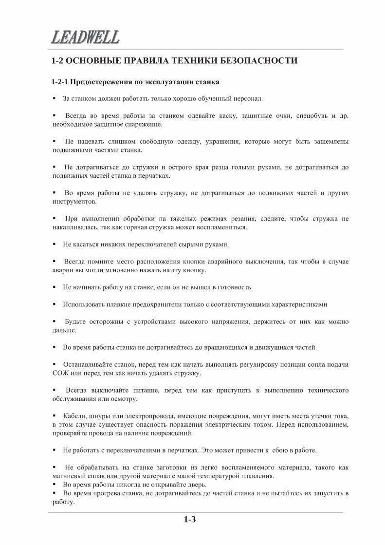
. - , , ,
X, Y Z, , ,
, . .
, . , .
, , .
1-10
1-4-1

2-1
2 MACHINE FEATURE:
2-1 NOMENCLATURE: V-30
ITEM DESCRIPTION
1 COLUMN UNIT
2 SPINDLE HEADSTOCK UNIT
3 SPINDLE UNIT
4 TABLE UNIT
5 SADDLE UNIT
6 BASE UNIT
7 DUAL COIL TYPE CHIP CONVEYOR
8 SHEET METAL ENCLOSURE GUARDS UNIT
9 OPERATION CABINET UNIT
10 THREE AXES TRANSMISSION UNIT & TELESCOPIC COVERS
11 POWER CABINET UNIT
12 COOLANT TANK UNIT
2. 2-1

2-2
V-40
ITEM DESCRIPTION
1 AUTOMATIC TOOL CHANGER UNIT
2 BASE UNIT
3 SADDLE UNIT
4 TABLE UNIT
5 SPINDLE HEADSTOCK UNIT
6 SPINDLE UNIT
7 SHEET METAL ENCLOSURE GUARDS UNIT
8 OPERATION CABINET UNIT
9 THREE AXES TRANSMISSION UNIT & TELESCOPIC COVERS
10 COLUMN AND BALANCE WEIGHT UNIT
11 POWER CABINET UNIT
12 COOLANT TANK UNIT

2-3
2-2 MACHINE OUTLINE DIMENSION: 2-3 :
V-30 VW01002900

2-4
V-40 VW01003000

2-5
MACHINE OUTLINE DIMENSION (OPTION) ( )
V-30 VW01002901 ( : )

2-6
V-40 VW01003001 ( : )

2-7
2-3 SPECIFICATION OF MACHINE: V-30
Capacity X-axis travel mm(in) 760(30)
Y-axis travel mm(in) 410(16)
Z-axis travel mm(in) 410 (16)
Distance from table(pallet) top to spindle end mm(in) 130-540(5.1-21.3)
Distance from column front to spindle center mm(in) 438(17)
Table Size of working surface mm(in)xmm(in) 890x400(35x15.7)
Permissible mass of workpiece kg(lb) 300(660)
Table working surface configuratin mm(in) 18Tx125x3
Height from floor to table top mm(in) 830(32.6)
Spindle Spindle speeds min-1 8000
Number of spindle speed ranges 1
Spindle nose(nominal size,NO.) 7/24 Taper,NO40
Spindle bearing inner diameter mm(in) 70 (2.75)
Ratios 1:1
Max. spindle torque N.M(ft.lbf) 95.5(70.4)
Transmission H.T.D Belt
Tool clamping force Kg(lb) 800 (1760)
Feedrate Rapid traverse m/min(IPM) 20/20/15(66/66/50)
Feedrate m/min(IPM) 5(16.6)
Jog feedrate mm/min(IPM) 1260(49.6)
A.T.C Drum type Arm type Tool shank(nominal size,NO.) BT-40
Retention knob(nominal size,NO.) MAS-P40T-I JIS-B-6339
Tool storage capacity 20 24
Max. tool diameter(with adjacent tools) mm(in) 95(3.7) 80(3.15)
Max. tool diameter(without adjacent tools) mm(in) 150(5.9) 110(4.3)
Max. tool mass kg(lb) 7(15.4) 7(15.4)
Max. tool length mm(in) 250(9.8) 250(9.8)
Tool change time tool to tool sec 7.5 3
Tool change time chip to chip sec 13 10
Tool selection Random
2-3
X
Y
Z
( )
-
( , )
.
( )
( )
( )
( )
( )
( )
( )
( )
( )
-1
( )
. ( . . )
( )
/ ( / )
/ ( / )
/ ( / )
7/24 40
HTD
.
( , )
( , )
. ( )
. ( )
( )
.
( )
.
.
( )
( )
( )
( )

2-8
A.P.C Number of pallets
Method of pallet change
Pallet changing time sec
MAG drive method
Motors FANUC Motor typeSpindle motor 30min/cont KW(HP) 7.5(10) p12/8000i
X-axis feed motor KW(HP) 1.2(1.6) c8/2000i
Const torque Nm 8
Thrust force Kgf 410
Ball screw mm 36xP10x1248L
Goo-G G 0.23
Y-axis feed motor KW(HP) 1.2(1.6) c8/2000i
Const torque Nm 8
Thrust force Kgf 410
Ball screw mm 40xP10x888L
Goo-G G 0.23
Z-axis feed motor KW(HP) 1.8(2.4) c12/2000i
Const torque Nm 12
Thrust force Kgf 610
Ball screw mm 40xP10x1120L
Goo-G G 0.175
Hydraulic pump motor KW(HP)---
Lubricant pump motor W4
Coolant pump motor KW(HP)50HZ-0.5(0.67) / 60HZ-0.76(1)
Guide way X guide way LG24-35-1640L-2
Width mm(in) 334 (13.1)
Guide distance mm(in) 472 (18.5)
Y guide way LG24-35-1000L-2
Width mm(in) 694 (27.3)
Guide distance mm(in) 445.5 (17.5)
Z guide way LG24-35-1080L-2
Width mm(in) 434 (17)
Guide distance mm(in) 464 (18.2)
Power sources Electrical power supply KVA 25
(30 / .)
Y
Z
( )
( )
( )
( )
( )
( . .)
( )
( )
( )
( )
( )
( )
Z
Y
*
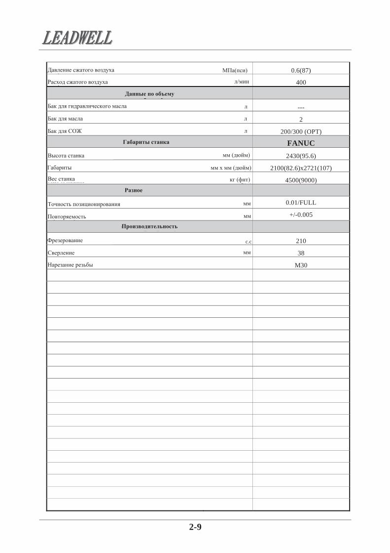
2-9
Compressed air pressure Mpa psi 0.6(87)
Compressed air flow rate L/min 400
Capacity Hydraulic oil tank L ---
Lubricant tank L 2
Coolant tank L 200/300 (OPT)
Machine size FANUC Height of machine mm(in) 2430(95.6)
Floor space mmxmm(in) 2100(82.6)x2721(107)
Mass of machine Kg(lb) 4500(9000)
Miscellaneous Positioning accuracy mm 0.01/FULL
Repeatability mm +/-0.005
Cutting capacity
Milling c.c 210
Drilling mm 38
Tapping M30
( )
/
( )
( )
( )

2-10
2-3 SPECIFICATION OF MACHINE: V-40
Capacity X-axis travel mm(in) 1020(40.2)
Y-axis travel mm(in) 510(20.1)
Z-axis travel mm(in) 510 (20.1)
Distance from table(pallet) top to spindle end mm(in) 160-670(6.3-26.4)
Distance from column front to spindle center mm(in) 515(20)
Table Size of working surface mm(in)xmm(in) 1200x510(4721x19.7)
Permissible mass of workpiece kg(lb) 500(1100)
Table working surface configuratin mm(in) 18Tx100x5
Height from floor to table top mm(in) 830(32.6)
Spindle Spindle speeds min-1 8000
Number of spindle speed ranges 1
Spindle nose(nominal size,NO.) 7/24 Taper,NO40
Spindle bearing inner diameter mm(in) 70 (2.75)
Ratios 1:1
Max. spindle torque N.M(ft.lbf) 114.6(84.5)
Transmission H.T.D Belt
Tool clamping force Kg(lb) 850 (1870)
Feedrate Rapid traverse m/min(IPM) 20/20/15(66/66/50)
Feedrate m/min(IPM) 5(16.6)
Jog feedrate mm/min(IPM) 1260(49.6)
A.T.C Drum type Arm type Tool shank(nominal size,NO.) BT-40
Retention knob(nominal size,NO.) MAS-P40T-I JIS-B-6339
Tool storage capacity 20 24
Max. tool diameter(with adjacent tools) mm(in) 95(3.7) 80(3.15)
Max. tool diameter(without adjacent tools) mm(in) 150(5.9) 110(4.3)
Max. tool mass kg(lb) 7(15.4) 7(15.4)
Max. tool length mm(in) 250(9.8) 250(9.8)
Tool change time tool to tool sec 7.5 3
Tool change time chip to chip sec 13 10
Tool selection Random
2-3
X
Y
Z
( )
( )
( )
( )
( )
( )
( )
( )
( )
( )
-
( , )
.
( )
. ( . . )
( )
-1
7/24 40
HTD
/ ( / )
/ ( / )
/ ( / )
( , )
( , )
. ( )
. ( )
.
.
( )
( )
( )
( )
( )
( )
.
.
2-11
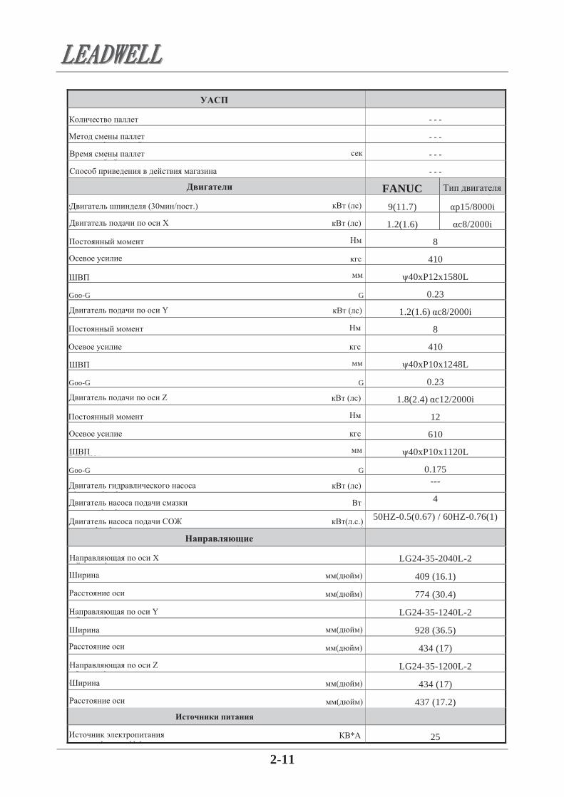
A.P.C Number of pallets
Method of pallet change
Pallet changing time sec
MAG drive method
Motors FANUC Motor typeSpindle motor 30min/cont KW(HP) 9(11.7) p15/8000i
X-axis feed motor KW(HP) 1.2(1.6) c8/2000i
Const torque Nm 8
Thrust force Kgf 410
Ball screw mm 40xP12x1580L
Goo-G G 0.23
Y-axis feed motor KW(HP) 1.2(1.6) c8/2000i
Const torque Nm 8
Thrust force Kgf 410
Ball screw mm 40xP10x1248L
Goo-G G 0.23
Z-axis feed motor KW(HP) 1.8(2.4) c12/2000i
Const torque Nm 12
Thrust force Kgf 610
Ball screw mm 40xP10x1120L
Goo-G G 0.175
Hydraulic pump motor KW(HP)---
Lubricant pump motor W4
Coolant pump motor KW(HP)50HZ-0.5(0.67) / 60HZ-0.76(1)
Guide way X guide way LG24-35-2040L-2
Width mm(in) 409 (16.1)
Guide distance mm(in) 774 (30.4)
Y guide way LG24-35-1240L-2
Width mm(in) 928 (36.5)
Guide distance mm(in) 434 (17)
Z guide way LG24-35-1200L-2
Width mm(in) 434 (17)
Guide distance mm(in) 437 (17.2)
Power sources Electrical power supply KVA 25
(30 / .)
( )
( )
Y
( )
Z
( )
( . .)
( )
Y
Z
( )
( )
( )
( )
( )
( )
*

2-12
Compressed air pressure Mpa psi 0.6(87)
Compressed air flow rate L/min 400
Capacity Hydraulic oil tank L ---
Lubricant tank L 2
Coolant tank L 200/300 (OP)
Machine size FANUC Height of machine mm(in) 2585(101)
Floor space mmxmm(in) 2990(117.7)x2929(115)
Mass of machine Kg(lb) 5400(11880)
Miscellaneous Positioning accuracy mm 0.01/FULL
Repeatability mm +/-0.005
Cutting capacity
Milling c.c 210
Drilling mm 38
Tapping M30
( )
/
( )
( )
( )

3-1
3. TRANSPORTATION:
3-1 PRECAUTION:
3. 3-1
1. , , .
2. , , , ,
. . ( . ).
3. , - .
. 4. . 5. - , ,
. 6. .
, . 7. , ,
, - . 8. , , ,
. , .
9. ,
.
. .

3-2
3-2. TRANSPOTATION DRAWING
3-2 5
= 4500
V-30
V-30
5
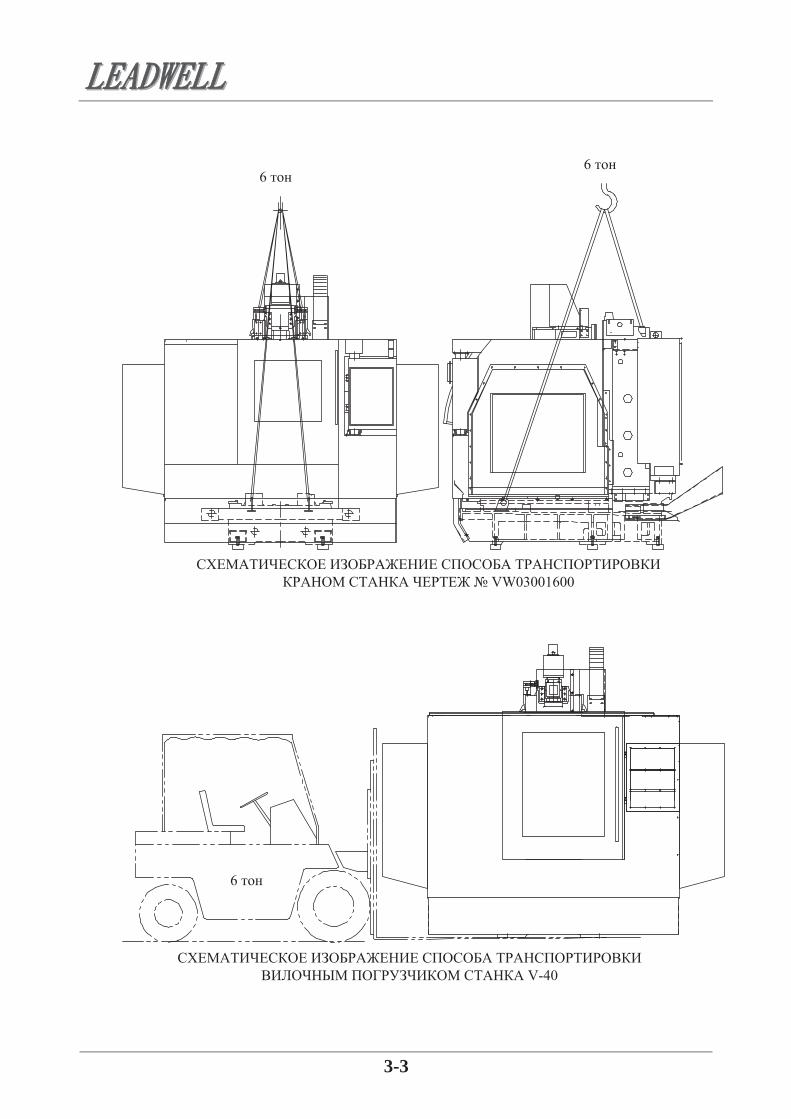
3-3
6 6
VW03001600
V-40
6
3-4
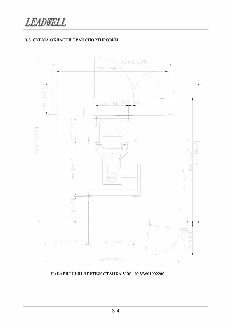
3-3. TRANSPORATION-FLOOR DRAWING 3-3.
V-30 VW01002200

3-5
V-40 VW01002100

4-1
4. INSTALLATION AND PREPARTION:
4-1 PRECATION:
4-2. ENVIRONMENTAL REQUIREMENT:
4. 4-1
(1) , , .
(2) , .
(3) , , . (4) . (5) . (6) ,
. (7) , .
. (8) , ,
. , .
4-2
(1) . 0 400 .
(2)
. 75% . (3) ,
, - . (4) . (5) , . ( ) 5000 / 2. (6) ,
. (7) .
100 , . (8) , , 85 . (9) , .
.

4-2
4-3 THE PRECEDURE OF INSTALLATION MACHINE: 4-3 1. . 2.
.
( 24)
( 24)
VW2001800
4-3
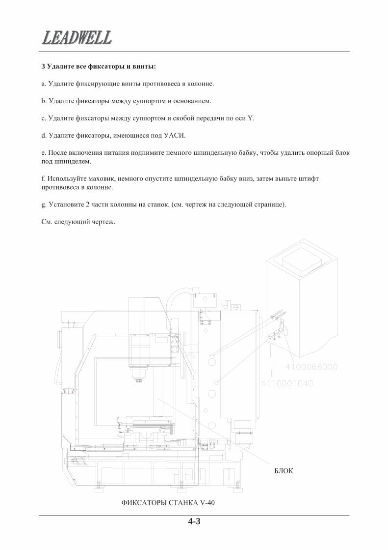
3. Remove all the fixed blocks and screws: 3 : a. .
b. . . Y. d. , . . ,
. f. , ,
. g. 2 . ( . ).
. .
V-40

4-4
, .
V-40

4-5
4. Install the accessaries:
5. Replace the z-axis motor on transmission housing, if is removed:
4 : a. y. b. . c. . d. . e. , .
5. Z , : a. S1 Z. b. S2 Z. ( . ). c. 3 , .
( 10 )
( 6 )
Z V-40

4-6
6. THE PROCEDURE OF ADJUSTING LEVEL :6. : 1. . 2. , . 3. , .
4. X 510 Y -255 . , . 0,01 .
5. Y -510 ( V-40), , 0,01 (V1) / 0.04 (V2).
6. Y -255 , X 1020 . 0,05 (V1) / 0.04 (V2).
7. .

4-7
7. Correct the drum type tool changing position: 7. : a. Z . b. , / ,
0,6-0,8 ( ).
a. , M19. b. ,
. c. . d. M21, M22
. e. , ,
. f. Z
, , 1850 (Z) 21MB/18MC, Fanuc. g.
, , .
h. , , .

4-8
7-1. ( ): (a) Z . (b) , / ,
0,6-0,8 ( ).
(c) MPG ( ). (d) SPDL ORIEN ( ). (e) DGONS PARAM ( ). (f) ( . ). (PARAM). (g) ( . “PAGE”). ( ). (h) MDI. (i) l. [ (PWO=0 ( ), PWO=1 ( )]. (j) INPUT. ( 100).

4-9
SP
(k) DGONS PARAM ( ). (l) ( . ) (DGNOS) ( ). (m) NO L Q P. (n) 5, 2, 5. ( D0525 10000000). (o) INPUT ( ). (p) 1 0 1 1 0 0 0 0. (q) INPUT. ( D0525 10000000).
(r) ( , .) MPG, SP.
(s) ( CYCLE, , ). (t) ,
( 5,90+0,05 , 3,3+0,05 ). ( , D0526 00100000 D0526 00100001
CYCLE START ( ). ( ,, ).
(u) DGNOS “D0525 10000000” “D0526 00100000” PARAM “PWO=0”. (v) MDI M 6 /.# EOB (
.

5-1
5. KEY PARTS FEATURES
5-1 PNEUMATIC SYSTEM : 5-1-1. FRL UNIT :
5. 5-1 5-1-1
( ) MY
5-2
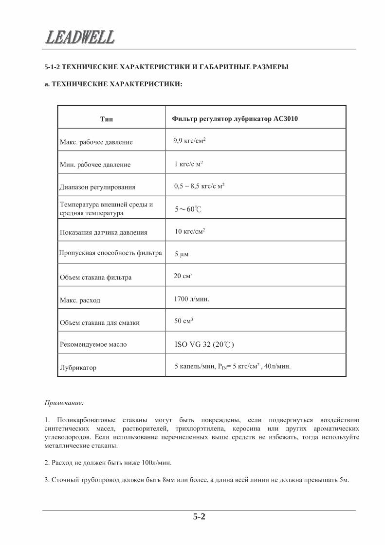
5-1-2. TECHNICAL DATA AND OUTLINE DIMENSION :
a. TECHNICAL DATA :
TYPE AC3010 FILTER REGULATOR LUBRICATOR
NOTE :
5-1-2 a. :
AC3010
.
.
.
5 / , PIN= 5 / 2 , 40 / .
9,9 / 2
1 / 2
0,5 ~ 8,5 / 2
10 / 2
5 μ
20 3
1700 / .
50 3
: 1. ,
, , , . , .
2. 100 / . 3. 8 , 5 .

5-3
b. OUTLINE DIMENSION :
5-1-3. THE SETTING METHOD OF FRL UNIT :
b. :
-
( )
5-1-3
a. , . b. . , , ( . ).
. : , - - . d. . . , , - , ( ) .
5-4
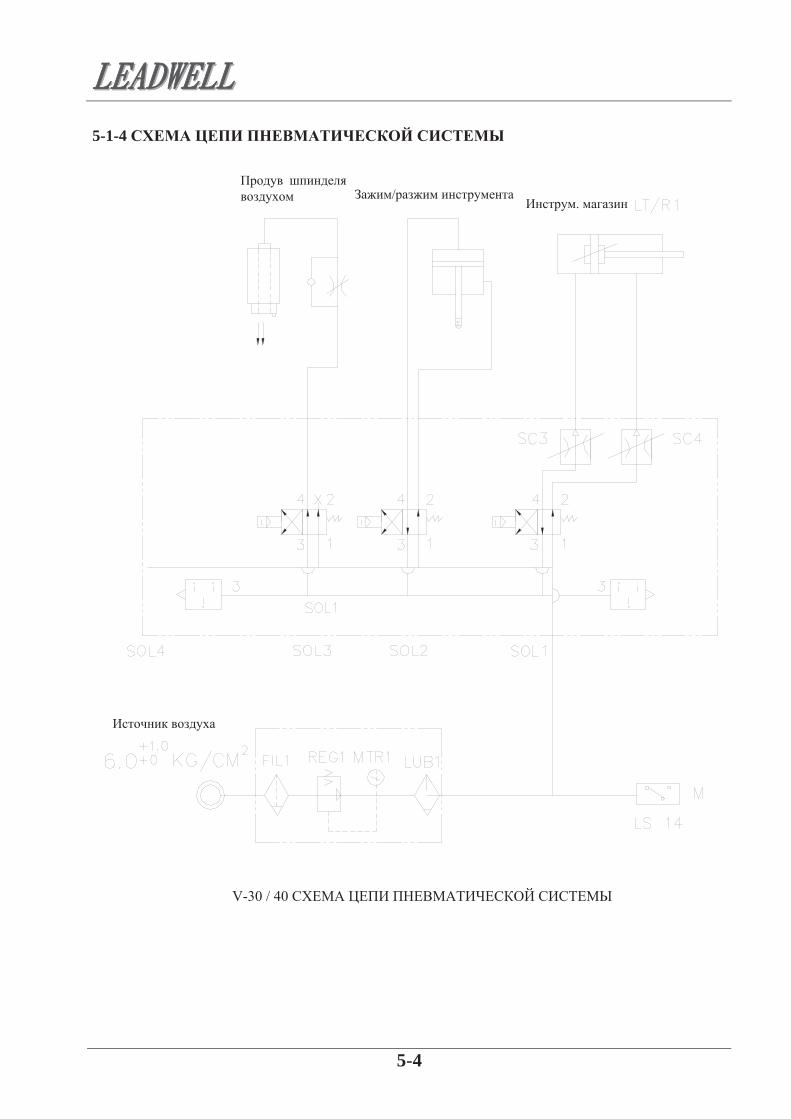
5-1-4. THE LOOP SKETCH OF PNEUMATIC SYSTEM :5-1-4
.
/
V-30 / 40
5-5
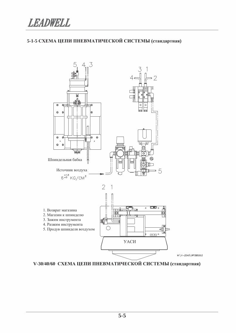
5-1-5 THE ROUTE SKETCH OF PENUMATIC SYSTEM(STANDARD) 5-1-5 ( )
1. 2. 3. 4. 5.
V-30/40/60 ( )

5-6
5-1-6 OPTION FOR AUTOMATIC TOOL LENGTH MESUREMENT 5-1-6
1. 2. 3. 4. 5. 6.
V-30/40/60 ( )

5-7
5-2 COOLANT SYSTEM:
5-2-1 OUTLINE DIMENTION OF COOLANT PUMP:
5-2-2 TECHNICAL DATA :TYPE GRUNDFOS CH4-20
5-2-3 POSITION OF TERMINAL BOX :
5-2-4 PIPEWORK :
5-2 5-2-1
5-2-2
. . .
. 10 (00 - +400 ) 6 (+410 - +900 )
. 0,7 (200 /50 ) 0,68 (200 /60 )
5-2-3
00, 900, 1800. .
5-2-4 a. , , ,
. , ,
. b.
, . c. ,
. d. ,
, , .

5-8
5-2-5 ELECTRICAL CONNECTIONS :
NOTE :
5-2-6 PHASE OF THE PUMP :
NOTE :
‘
5-2-7 TROUBLE SHOOTING :FAULT CAUSE
5-2-5 a. . b. , . c. .
: , .
5-2-6 a. (1 110/220 , 60 )
. , , .
b. , , .
: 1. ,
. 2. ,
. 3. ,
, . 4. ,
.
5-2-7
, , .
.
. .
. .
, . . .
. .
.
( ). .
. .
.
.

5-9
5-3 SPINDLE OIL COOLER SYSTEM
5-3-1 OUTLINE DIMENSION:
5-3-2 CIRCUIT DIAGRAM:
5-3 5-3-1
: CO-4PT (L050250t20)
½”pt
½”pt
5-3-2
.

5-10
5-3-3 WIRE CONNECTION:
“ ”
5-3-4 GENERAL CAUTION:
5-3-3
1. , RST , . 2. . 3. 23 250 . 4. « ». 5. , RST
.
5-3-4
. , ,
.
,
50
,
60 - , .
- .
3. 22-32 . , , ,
, , , , , ,
. 3. , , . 4. , ,
. 5. , 4 - 8 / 2. 6. 3 / 2.

5-11
5-3-5 MAINTENANCE :
. ( . ).
500 500
8. 100 150 ( 10-15 ).
. , ,
. 9. 10
. 10. , 3 . ,
- .
5-3-5
1. , .
2. , , , .
. 3. ,
. 4. . 5. .
5-12
5-3-6 TROUBLE SHOOTING:
SITUATION CAUSE REMEDY
NOTE :
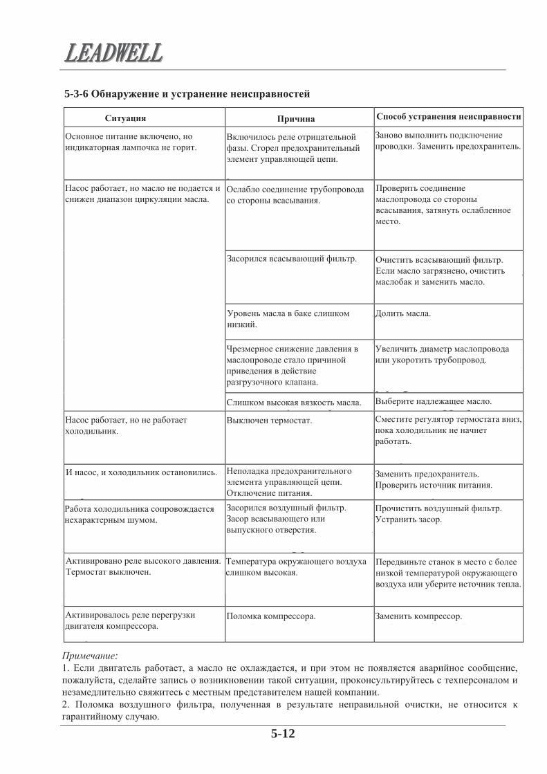
5-3-6
. .
, .
, .
, .
, .
.
.
.
.
.
.
.
.
.
.
.
.
. .
.
.
.
. .
, .
. ,
.
.
.
.
,
.
. .
. .
.
: 1. , , ,
, , .
2. , , .

5-13
5-4 LUBRICATION SYSTEM 5-4-1. OUTLINE DIMENSION:
5-4-2. FILL UP LUBRICATION OIL:
NOTE :
5-4
5-4-1.
CESM
-
5-4-2. a. ,
. b. . c. ,
, . . .
d. , -.
e. , , , . ,
- . f. ,
.
: 1. , , . 2. , , ,
Leadwell . 3. , MOBIL VACTRA OIL 2, SHELL OIL T68, ESSO FEBISK68 .

5-14
5-4-2-1 OIL RECOMMENDATION : 5-4-2-1 :
:

5-15
5-4-3 THE LUBRICATION SYSTEM SKETCHES OF AXES :5-4-3 :
Y
Y
Z
Z
V-40

5-16
5-4-4 THE LUBRICATION SYSTEM SKETCHES OF AXES :5-4-4 :
V-40 3
Z
Y

5-17
5-5 HEAT EXCHANGER SYSTEM :
5-5-1 OUTLINE DIMENSION OF HEAT EXCHANGER :
5-5-2 GENERAL CAUTION :
5-5-3 SPECIFICATION AND TECHNICAL DATA :
TYPE EA-5AR
5-5 : 5-5-1 :
-5 R ( )
5-5-2 :
1. , .
2. .
3. .
4. .
5-5-3 :
. ( /° )
. 220
350

5-18
5-5-4 BASIC MAINTENANCE : 5-5-4 :
1. . 2. , ,
. 3. , . 4. , , ,
- . 5. , , .(CP4) 6. , , . 7. , - .

6-1
6 OPERATION:
6-1 MISCELLANEOUS FUNCTION (M FUNCTION/M CODE) :
6-2 SPECIFYING THE SPINDLE SPEED (S FUNCTION/S CODE) :
NOTE 1 :
NOTE 2 :
6-3 TOOL NUMBER CODE (T FUNCTION/T CODE) :
NOTE :
6-4 SPECIFYING THE FEED RATE (F FUNCTION) :
6.
6-1 (M / M )
, , / , / , , , . ., M 2 . M , , .
6-2 (S / S )
, , 4 , S.
S45 45 /S4000 4000 /
: S500* M03* S3500* M05* M04* 300 /
1: S , .
2: M03
M04, . M05, .
6-3 (T / T )
2 , , 0 99. :
M06 T02* 2
: T, , . T
M06, .
6-4 (F )
a. 1 5000, F, ,
.

6-2
NOTE :
NOTE 1NOTE 2 :
6-5 PREPARATORY FUNCTION (G FUNCTION) :
6-6 PROGRAM
6-6-1 SEARCHING OR CALLING PROGRAMS :
Classification Function Key switch Setting PWE=1
Mode switch button
Function button
Operation
F ( / ) ( / )
b. ( ) : G01 X150.0 F80* G02 X200.0 Y300.0 R400* G03 X250.0 Y50.0 R100.0 F300* : “FXXXX” G01, G02 G03. c. “FXXXX” G00 ( ).
1: F / , / , .
2: “0”.
6-5 (G )
“GXX” , G, . .
6-6 6-6-1
.
PWE=1
EDIT( )
EDIT/AUTO ( -
/ - )
AUTO (
)
EDIT( )
OFFSET ( )
PROGRAM ( )
PROGRAM ( )
PROGRAM ( )
PROGRAM ( )
[ ]( )
[O] [ ]( )
[P/Q] [INPUT] ( )
[ ] ( )
[N]
[ ]( )

6-3
6-6-2 PROGRAM EDITING: Classification Function Key switch Setting
PWE=1Mode switch
button Function button
Operation
�
� �
�
�
��
��
��
6-7 COORDINATION SYSTEM : 6-7-1 PROGRAMMING ZERO POINT :
6-6-2
PWE=1 .
EDIT/AUTO ( -
/ - )
EDIT ( )
EDIT ( )
EDIT ( )
EDIT ( )
EDIT ( )
EDIT ( )
EDIT ( )
PROGRAM ( )
PROGRAM ( )
PROGRAM ( )
PROGRAM ( )
PROGRAM ( )
PROGRAM ( )
PROGRAM ( )
PROGRAM ( )
, New
date[insert]
[P] [ INPUT] ( )
[O] - 9999 [DELET] ( )
[O] [DELET]
[N] [INPUT] ( )
,
[DELET]
, New
date[ALTER]
6-7 6-7-1
, .
. , ,
.

6-4
6-7-2 COORDINATION SYSTEM :
6-7-3 THE FLOWCHART OF ATC OPERATION :
6-7-2
3 3 , .
6-7-3

6-5
6-8 MDI KEYBOARD & PANEL 6-8

6-6
OPERATION PANEL
SMALL PANEL

6-7
6-9 MDI KEYBOARD FUNCTIONS : 6-9 MDI ( )
, .
, ( ) .
, .
,
.
( ), ,
.
, , .
Shift , /
.
Input - ,
.

6-8
Message ,
.
.
, .
, .
.
, .
Offset setting
.
System ,
.
Custom graph .

6-9
6-10 FUNCTIONAL BUTTONS DESCRIPTION : 6-10 :
.
.
.
.
,
. ( ,
)

6-10

OPERATION SELECTION :
6-11
Z
, .
, “/” .
, 01,
.
, F
.
M, S, T B
.
,
, M, S, T, B.
,
.
.
Z

6-12
.
M, S,
T .
.
.
. ( )

6-13
FUNCTIONS OF SMALL PANEL :
.
.
MPG ( ),
,
. , ,
( CE ).
“Feedhold”, .
,
.
“MPG”, ,
.
6-14
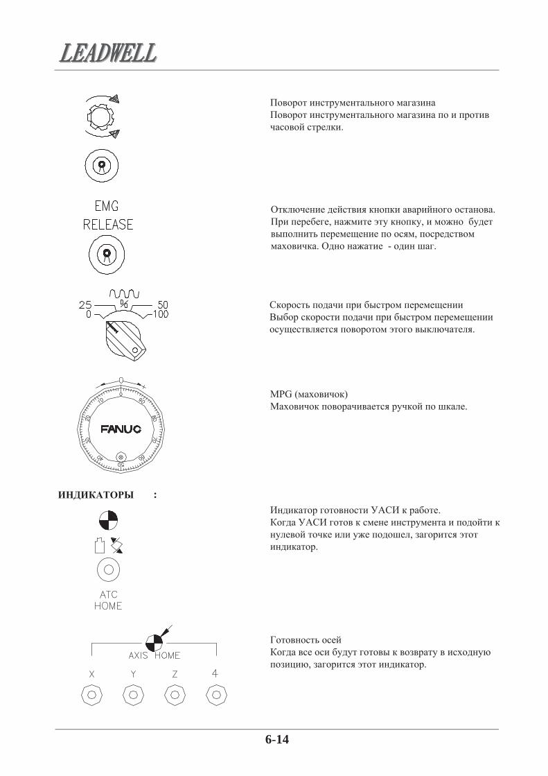
INDICATE LAMP :
.
. , ,
, . - .
.
MPG ( ) .
.
, .
, .

6-15
ALARM LAMP :
:
,
.
,
.
, ,
.
, ,
.
, ,
.
6-16
6-11 FUNCTION OPERATION : 6-11-1 POWER ON AND OFF :
6-11-2 MANUAL FEED :
6-11-3 RETURN TO REFERENCE POINT :
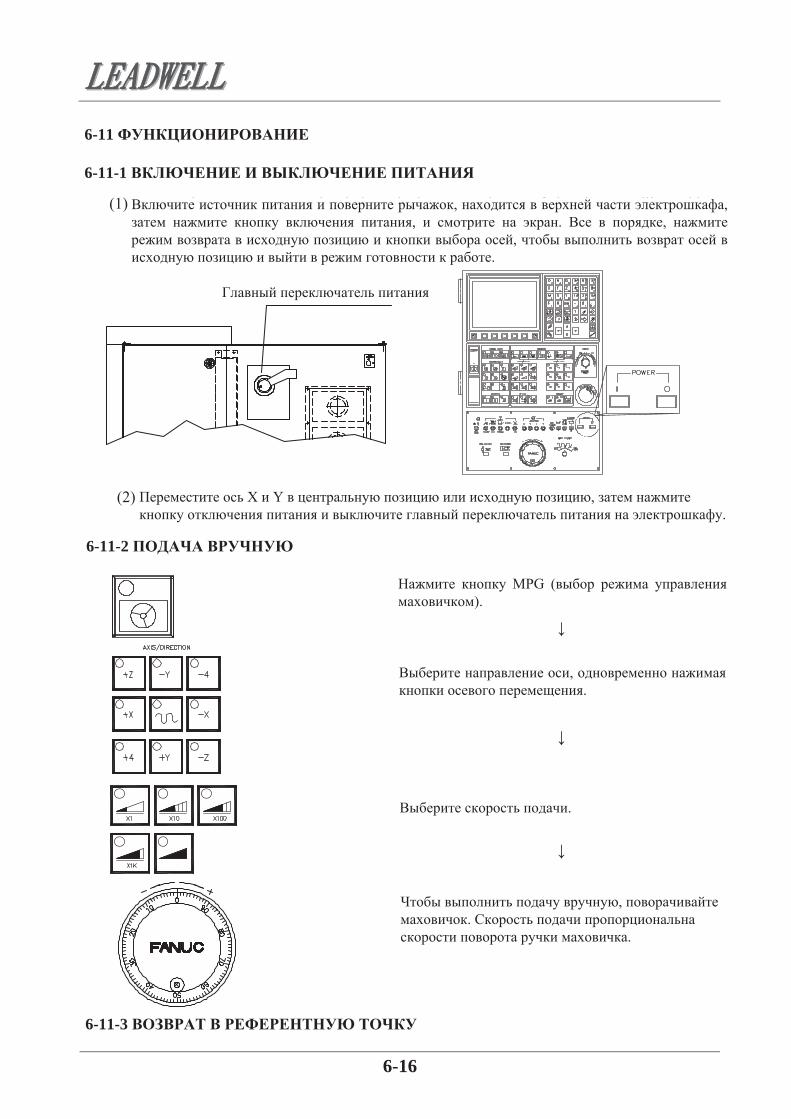
6-11 6-11-1
, , , . , ,
.
X Y , .
6-11-2
.
MPG ( ).
, .
, .
.
6-11-3

6-17
6-11-4 SPINDLE START :
, .
“HOME” ( ).
. ( ).
.
“Home Start”, .
6-11-4
,
. ( :
S.)
HOME, JOG,INCREASE JOG, MPG TEACH.
MDI ( ), (S ).
( - : CW-
, CWW - ).

6-18
6-11-5 INCREASE JOG FEED :
6-11-6 JOG FEED :
6-11-5 JOG
, , , .
.
INC JOG ( ).
.
. 0.001 0.01 0.1 1
6-11-6
JOG ( - ).
, . -
.
.

6-19
6-11-7 RAPID TRAVERSE :6-11-7
TRAVERSE ( )
: “+” “-“. , .
JOG ( ).
.
15 /
(100%)
X
Y
Z
20 /
20 /
7-1
7 CLEAN AND MAINTENANCECAUTION :
7-1 DAILY MAINTENANCE :
7-1-1 BEFORE POWER ON :
7-1-2 AFTER POWER ON :
7-1-3 AFTER FINISHING DAILY WORK :
1. - , .
, . 2. ,
- , .
7.
:
7-1 7-1-1
a. , .
b. , . c. , . d. , 0. e. , .
7-1-2
a. , .
b. . c. , . d. 6 / 2. e.
3-6 3/ . f. . g. , , . h. , ,
.
7-1-3
a. , . b. , . c. , . ,
.

7-2
7-2 WEEKLY MAINTENANCE :
7-3 SEMIANNUAL MAINTENANCE :
d. , , .
e. . f. - , .
( . ). .
V.
,
7-2
a. . b. . c. , . d. . e. . f. . g. .
7-3 , a. . b. , . c. , .
, , . .

7-3
7-4 ANNUAL MAINTENANCE :
7-5 ENVIRONMENTAL CLAIMS :
7-6 OUR GOAL :
d. . e. , . f. . g. , . h. , . i.
, .
j. , , .
7-4
a. , , . b. .
. c. , . d. .
, .
e. .
7-5
. Leadwell, ,
, . .
, , . ,
.
7-6 1. :
, ,
. , . 2. :
. , , , .

7-4
7-7 WASTE TREATMENT :
3. : . .
4. : ;
. , .
7-7 1.
a. : - ,
. , . , ,
, . , ,
. b. :
. . .
, . c. :
. .
2.
, : , ,
. , . , , , . . , ,
, , . . , .
, .

A-1-1
I - M
M
. .
.
.
. .
.
.
. 01
, .
. Z
.

A-1-2
M
4 4
4 . 4 4 . 4
4
.
. .
. . .
. . . Y
. . . 4
66

A-1-3
M
. .
. . .
. . . Y
. . . Z
. . . 4
/
/ 83: 84:
84: 83:
.- .- .
.- .- .
.- .- .
.- .- .
.- .- .

A-1-4
M : :
. . .
. . . .
Renishaw Renishaw

A-1-5
: :
M
4 4
.
. .
. . .
. . . Y
. . 4
5 5
Z . Z .
. .
. . 5
.

A-1-6
: :
M . . .
. . . Y
. . . 4
. . . 5
/
/
83: 84: 84: 83:
.- .-
.- .-
.- .-

A-1-7
II - G
G G
/ / ,
Y Z Y Z
Y Z
. .
+ -
1 2 3 4 5 6

A-1-8
G G
/
. . R
( 1) G G , .
( 2) G 00 . , .
( 3) G , G , G , , ( 010).
( 4) G , G .
( 5) 01, , G80. , G
01 G . ( 6) G .

����APPENDIX���� 【 】

Caution: Spindle Operation A. SPINDLE AIR PURGE
1.Set spindle air purge pressure at 1.2kg/cm2 1.5kg/cm2. Caution At power on for turning, check spindle air purge is functioning correctly. Caution Do not turn off spindle air purge or adjust pressure, it will lead to spindle
defected or damage of spindle.
B. SPINDLE OIL COOLER 1. Spindle shaft and quill with temperature difference may lead to spindle bearing
burns. Spindle oil cooler temperature set up have to 2°C higher than room temperature.
2. Rotary type of spindle oil cooler temperature is 25°C at initial. Pls. adjust according to machine site.
3. Digital spindle oil cooler will detect spindle room temperature, no more adjustment is required.
Caution At power on for turning, check spindle oil cooler is functioning correctly.
C. SPINDLE WARM UP To ensure spindle smooth rotation in long term and long lifetime, at machine, installation or daily turn on, follows spindle warm up operation.
D. SPINDLE TEMPERATURE INCREASE 1. This machine spindle was build up with high accuracy of spindle angular ball bearing of which add with high temperature endurable grease lubricator effective for maintain its accuracy with low temperature increasing at rotation. 2. If spindle temperature increased higher than 20°C of room temperature, this indicates abnormal of the spindle. Contact machine builder immediately for authorized engineer delicate for maintenance will be required. Caution None authorized personnel disassembling spindle is prohibited. In case this accident happened, any failure to the spindle is subject to customer’s obligation.
E. SPINDLE HIGH SPEED ROTATION TIME MANAGEMENT Ref. table 1
1. Extreme speed of spindle rotation do not exceeds 1/4 of daily working hours. 2. Spindle speed stay less than normal rotation speed 85% of extreme spindle
speed for machining. 3. Spindle run at normal continuous rotation speed do not exceed 8 hours a day.
Otherwise, lower normal rotation speed to 70% of spindle speed, or reduce spindle speed to minimum speed for 1 hour will be required.
. 1. 1,2-1,5 / 2
: : ,
. .
. 1. .
2 , . 2. 25 .
, , . 3.
, . : .
C.
, .
D. 1. , , .
, .
2. 20 , , .
.
: . , , .
. 1. ¼ . 2. 85% . 3. 85%
8 . , 70% , Min 1 .

4. Spindle speed less than minimum speed is not allowed. Table 1 Spindle specification
Extreme speed of Spindle rotation
Normal spindle rotation speed at
85% of Spindle peak
Minimum speed
8000rpm 8000rpm 7000rpm - 10000rpm 10000rpm 8500rpm 3000rpm 12000rpm 12000rpm 10000rpm 5000rpm 15000rpm 15000rpm 12000rpm 6000rpm
F. SPINDLE GUARANTEE 1. Spindle of normal operation, general spare parts will be guaranteed for 1 year.
2. Spindle bearing guaranteed for 2000hrs of rotation.
4. .
1
85%
F. 1. , ,
- 1 2. - 2000
8 000 / 8 000 / 7 000 /10 000 / 10 000 / 8 500 /
10 000 /12 000 / 12 000 /
12 000 /15 000 / 15 000 /
3 000 /
5 000 /6 000 /


![Modification of [8,8,8-(PPh (H)-9-(Py)-nido-8,7- 9], Py = …digital.csic.es/bitstream/10261/64831/4/Modification of 8,8,8.pdf · 5 [8,8,8-(PR 3) 3-nido-8,7-RhSB 9 H 10], separatory](https://static.documents.pub/doc/80x56/5bac5a2009d3f279368d83b6/modification-of-888-pph-h-9-py-nido-87-9-py-of-888pdf-5-888-pr.jpg)