AN ISO 9001 & 14001 COMPANY TENDER DOCUMENT TENDER No: NERO/CON/ASR/RADHANAGAR/292 Dated 28.02.2018 FOR TENDER FOR DESIGN, MANUFACTURE, SUPPLY, INSPECTION, INSTALLATION, TESTING AND COMMISSIONING OF PACKAGE TYPE SEWAGE TREATMENT PLANT (75 KLD) OF MBBR TECHNOLOGY AND DEVELOPMENT WORKS FOR ASSAM RIFLES BATTALION AT RADHANAGAR, TRIPURA. VOLUME–II NOTICE INVITING TENDER ADDITIONAL CONDITIONS OF CONTRACT TECHNICAL SPECIFICATIONS DRAWINGS
and other materials for proper layout of the work in accordance with the scheme
for bearing marks acceptable to the Owner. The Centre, longitudinal or face lines
and cross lines shall be marked by means of small masonry pillars. Each pillar
shall have distinct marks at the centre to enable a theodolite to be set over it. No
work shall be started until all these points are checked and approved by the
Engineer-in-Charge in writing but such approval shall not relieve the Contractor
of any of his responsibility. The Contractor shall also provide all labour, material
and other facilities, as necessary, for the proper checking of layout and
inspection of the points during construction. Pillars bearing geodetic marks
located at the sites of units of works under construction should be protected and
fenced by the Contractor. On completion of works, the Contractor must submit
the geodetic documents according to which the work was carried out.
8.0 Responsibility for level and alignment
The Contractor shall be entirely and exclusively responsible for the horizontal
and vertical alignment, the levels and correctness of every part of the work and
shall rectify effectually any errors or imperfections therein. Such rectifications
shall be carried out by the Contractor, at his own cost, when instructions are
issued to that effect by the Engineer-in-Charge. It is highly possible that there
shall be more than one agency working at the same time at the site. The
contractor shall at all times remain bound to co-ordinate with the agencies,
deployed by EPI for the above works, including providing free access and making
required provisions for them in execution of works pertaining to their portion of
works. He shall also remain bound to ensure uninterrupted progress of work by
these agencies in a peaceful and smooth manner. He shall also remain bound to
make the required changes/additions/alterations in the works done by him to
accommodate the items under the scope of work of such other agencies
deployed by EPI or the client. The contractor is deemed to have made the
estimated allowances in this respect while quoting his rates at the tendering
stage.
Even though EPI has taken all care to attach all the drawings as vetted by the
client it shall be the responsibility of the contractor to interpret the drawings for
completion of the works under this contract.
ACC NIT No. NERO/CON/ASR/RADHANAGAR/292 Page 10 of 18
The list of minimum tools, plant and machinery to be provided by the contractor
within the period mentioned against the respective item is given at Annexure-A.
9.0 The following shall also be read with clause number 13 of the GCC:
a) The bidder/contractor must have valid GSTIN
b) The bidder/contractor must submit as a compliance under GST Act, the
invoices in GST complaint format failing which the GST amount shall be
recovered/ adjusted without any prior notice from the next invoices or
available dues with EPI.
c) The bidder/contractor are required to update/upload the GST/Taxes data
periodically so as to avail ITC credit by EPI failing which it shall be
recovered/adjusted by EPI without any prior intimation.
The rates quoted by the contractor shall be deemed to be inclusive of all taxes,
duties, Cess etc. except GST which shall be reimbursed to him subject to raising
of tax invoice and filing of return and payment of tax as per GST law, failing
which EPI shall not be able to honour his claims for any payment. The contractor
has quoted his rates knowing fully well that submission of return and display of
the same on GSTN portal is mandatory.
However, any variation in taxes and duties after submission of due date of
submission of tender shall be to the owner’s account i.e. in case of any decrease
in the taxes and duties shall be passed on to the owner and any increase in
taxes and duties shall be borne by the Owner. Similarly, the imposition of any
fresh taxes and duties shall also be borne by the Owner.
All the above reimbursements shall be admitted to the extent these are admitted
by the Owner.
10.0 i. The following shall stand added to the clause no 20 of GCC:
The contractor shall keep EPI indemnified against all claims, damages,
compensation and expenses payable, if any, in consequence of any accident,
or injury sustained by any workman or any other person employed by the
contractor.
ii. The following shall stand added to the clause no 23.2 of GCC:
Further the contributions on part of employer shall be paid by the Contractor.
These contributions shall be reimbursed by EPI/DGAR to the Contractor
against documentary evidence subject to a limit of 3.4 % of the Contract Price.
ACC NIT No. NERO/CON/ASR/RADHANAGAR/292 Page 11 of 18
11.0 The following shall stand added to the clause no 27.0 including its sub
clauses of GCC of EPI:
The contractor, within 10 days of issuance of LOI (Letter of Intent) to him shall
depute at least one graduate civil engineer with 5 years of post-qualification
experience and one person having diploma in civil engineering with 10 years of
post-qualification experience. The contractor shall also depute at least one
graduate electrical engineer with 5 years of post-qualification experience or one
person having diploma in electrical engineering with 10 years of post-qualification
experience as and when instructed by the Engineer-charge. Should the
contractor fail to provide them within such period or as directed by the Engineer-
in-charge, EPI shall be at liberty to recover an amount @30,000.00 per month
person from any amount including the retention money due to the contractor.
12.0 The clause no 28.3 of the GCC shall stand deleted.
13.0 No secured advance shall be paid to the contractor and hence clause no.
35.0 of GCC shall stand deleted.
14.0 The clause no. 43.2 shall stand amended as below:
The contractor shall execute the works so as to complete the works within the
stipulated completion time. He shall remain bound to submit a programme of
completion of items.
15.0 The following shall stand added to clause no 45.0 of the GCC:
The contractor shall at all-time remain bound to provide the samples in quantity
and manner as instructed by EPI to be analysed or tested in an outside
laboratory or in the field laboratory at site. The cost of testing charges is included
in the prices of the contractor. EPI shall, however, be at liberty to get the
materials tested independent of the contractor and the contractor shall remain
bound to render all assistance to EPI in conductance of such tests including
making available the materials in sufficient quantity and in time and payment of
the testing charges. EPI/client shall at all times have full access to the works and
to all workshops and places where work is being prepared or from where
materials, manufactured articles or machinery. The contractor shall afford every
facility and assistance and cost in obtaining the right and visit to such access.
EPI shall have full powers to require the removal from the premises of all
materials which in their opinion are not in accordance with the specifications and
in case of default, EPI shall be at liberty to employ at the expense of the
contractor, other persons to remove such materials without being answerable or
accountable for any loss or damage that may happen or arise to such materials.
EPI shall also have full powers to require other proper materials to be substituted
ACC NIT No. NERO/CON/ASR/RADHANAGAR/292 Page 12 of 18
thereof and in case of default by the contractor, may cause the same to be
supplied and all costs which may require such removal and substitution shall be
to the contractor’s account.
16.0 The following shall be added to clause no 52.6 of GCC:
The field testing laboratory to be established by the contractor at his cost shall be
equipped with the minimum number of testing equipment as per Annexure-B. In
case the contractor fails to provide them EPI shall get them installed and debit
the cost to the contractor.
17.0 The following provisions shall supersede that of clause no 69 of GCC
wherever applicable:
No claim on account of extra / substituted / variation of items etc. pertaining to
the contractor’s portion of work save and except what is admitted and paid by
Owner, shall be entertained or admitted by EPI. Any claim by the contractor, if
not paid by the Owner, whatsoever be the reason shall not be admitted by EPI.
But under no circumstances contractor shall suspend the work on the non-
settlement of rates under this clause.
18.0 In case the project execution is delayed beyond the contractual scheduled
completion period due to reasons attributable to the contractor, the staff and site
expenses of EPI for extended period shall be paid by him to EPI at the rate of Rs.
10,000/- per month. This shall be in addition to the other recoveries, if applicable
as per clause no 72 (including its sub clauses) of GCC and Penalties etc. if any,
levied by Owner for the works pertaining to the contractor’s scope of work. The
decision of EPI in this regard shall be final & binding on the contractor.
19.0 The work executed by the contractor shall be subject to audit and quality control
checks from Quality Control Division & Technical Audit of EPI, Client, and
Inspecting Agency of the Client and Chief Technical Examiner of Central
Vigilance Commission, Govt. of India. In the eventuality of any defect/
substandard works as brought out in the report or noticed otherwise at any time
during execution, maintenance period etc., the same shall be made good by the
contractor without any cost to EPI. In case the contractor fails to rectify the
defect/sub-standard work within the time period stipulated by EPI, EPI shall get it
rectified at the risk and cost of the contractor and shall recover the amount from
the dues of the contractor.
Further all works Executed by the contractor shall be subject to third party testing
to be deployed by EPI for which the expenses shall be borne by the contractor
within his quoted rates.
ACC NIT No. NERO/CON/ASR/RADHANAGAR/292 Page 13 of 18
20.0 Execution of Work. Once the contract is awarded a work order will be issued to
the contractor and site handed over and in no case this will be issued on back
date. Time for completion will commence from the date of issue of work order.
Engineer in charge will be nominated by name and communicated to all
concerned and during his absence relief will be given by name. Following
procedures to be ensured: -
(a) A Testing Laboratory will be established by the Agency or suitable tie up done
with approved testing laboratory or consultancy for quality check.
(b) Following registers/documents will be maintained and produced when asked
for: -
i. Hindrance recording register.
ii. Stage passing register.
iii. Site order book.
iv. Inspection register.
v. Materials testing register.
vi. Contractor ledger.
vii. Labour license.
viii. CAR/EAR/MCI Policy with STPI, Earthquake & TPL.
(c) Monthly progress will be monitored and forwarded to all concerned.
(d) Time extension if required must be processed well in advance before existing
completion date supported by documents like newspaper cutting, letter from user
etc.
(e) If any willful delay from contractor is noticed suitable action taken as per
contract condition and work to be completed by due date by resorting to alternate
means specified in contract conditions.
(f) Quality checks to be carried out at each level to be laid down percentage wise
during the process of execution.
(g) If any unforeseen delay occurs the same must be resolved by coordinating
with all stakeholders.
21.0 Preparation of Running Account Register. Work carried out by the contractor
should be jointly measured and entered in to the measurement book. Any
mistakes in the MB will be scored and initialed. Following documents to be
submitted along with RAR:
(a) Measurement Book.
(b) Photographs of the work carried out duly signed by Agency and SO1 Wks.
(c) Quality test reports from approved laboratory.
ACC NIT No. NERO/CON/ASR/RADHANAGAR/292 Page 14 of 18
(d) Recommended Liquidity Damages for delayed works.
(e) RAR Movement slip.
22.0 Completion and Handing over of Assets to User. Once the work is completed
certificate will be obtained from user and work officer of the sector and then the
same will be intimated to Engineers branch for ordering Board to verify and take
over assets. All construction materials and tools lying in the site will be removed
and assets will be kept ready for handing over to user. A performance report of
the contractor will be forwarded to the Engineers branch and all warranty will be
documented and handed over to the works officer of the sector.
It is mandatory to adhere to the guidelines for executing the works pertaining to
Assam Rifles. Any deviation or failure will be treated as violation of MoU and due
penalty will be imposed on the Agency charges and denial of future works.
23.0 ARBITRATION: Clause no. 76.1 of GCC shall stand amended as below:
76.1 Before resorting to arbitration as per the clause given below, the parties
if they so agree may explore the possibility of conciliation as per the
provisions of Part III of the Arbitration and Conciliation Act, 1996 as
amended by Arbitration and Conciliation (Amendment) Act, 2015. When
such conciliation has failed, the parties shall adopt the following
procedure for arbitration:
i) Except where otherwise provided for in the contract, any disputes and
differences relating to the meaning of the Specifications, Design,
Drawing and Instructions herein before mentioned and as to the
quality of workmanship or materials used in the work or as to
any other questions, claim, right, matter or things whatsoever in any
way arising out of or relating to the Contract, Designs, Drawings,
Specifications, Estimates, Instructions, or these conditions or otherwise
concerning the works of the execution or failure to execute the same
whether arising during the progress of the work or after the completion
or abandonment thereof shall be referred to the Sole Arbitrator
appointed by the Chairman & Managing Director (CMD) of Engineering
Projects (India) Limited (EPI) or any other person discharging the
functions of CMD of EPI. The person approached for appointment as
Arbitrator shall disclose in writing circumstances, in terms of Sub-Section (1)
of Section (12) of the Arbitration and Conciliation Act, 1996 as amended by
Arbitration and Conciliation (Amendment) Act, 2015 as follows:
a) such as the existence either direct or indirect, of any past or present
relationship with or interest in any of the parties or in relation to the subject-
matter in dispute, whether financial, business, professional or other kind,
ACC NIT No. NERO/CON/ASR/RADHANAGAR/292 Page 15 of 18
which is likely to give rise to justifiable doubts as to his independence or
impartiality; and
b) which are likely to affect his ability to devote sufficient time to the arbitration
and in particular his ability to complete the entire arbitration within a period of
twelve months.
The Arbitrator shall be appointed within 30 days of the receipt of letter of
invocation of arbitration duly satisfying the requirements of this clause.
ii) if the arbitrator so appointed resigns or is unable or unwilling to act
due to any reason whatsoever, or dies, the Chairman & Managing
Director aforesaid or in his absence the person discharging the duties of
the CMD of EPI may appoint a new arbitrator in accordance with these
terms and conditions of the contract, to act in his place and the new
arbitrator so appointed may proceed from the stage at which it was
left by his predecessor.
iii) It is a term of the contract that the party invoking the arbitration shall specify
the disputes, differences or questions to be referred to the Arbitrator under this clause together with the amounts claimed in respect of each dispute.
iv) The Arbitrator may proceed with the arbitration ex-parte, if either party, in spite of a notice from the arbitrator, fails to take part in the proceedings.
v) The work under the contract shall continue as directed by the Engineer-In-
Charge, during the arbitration proceedings.
vi) Unless otherwise agreed, the venue of arbitration proceedings shall be at the venue given in the 'Memorandum' to the 'Form of Tender".
vii) The award of the Arbitrator shall be-final, conclusive and binding on both the
parties. viii) Subject to the aforesaid, the provisions of the Arbitration and Conciliation
Act, 1996 as amended by Arbitration and Conciliation (Amendment) Act, 2015 or any statutory modifications or re-enactment thereof and the Rules made there under and for the time being in force shall apply to the arbitration proceedings and Arbitrator shall publish his Award accordingly.
23.1 Clause no 76.2 & 76.3 of GCC shall remain un-changed.
24.0 EPI has awarded this contract on behalf of DGAR (Director General Assam
Rifles), Owner. In case EPI ceases to or exits from the project the right and
responsibility etc. of EPI in the contract shall get transferred to DGAR (Director
General Assam Rifles) or his nominated agency(ies).
ACC NIT No. NERO/CON/ASR/RADHANAGAR/292 Page 16 of 18
25.0 Completion and taking over:
As soon as the works are completed the contractor shall inform EPI and EPI in
turn shall inform DGAR who will nominate a board of officers for
checking/verification of completed work as per the contract for final taking over of
the project.
A final certificate of rectification of all defects pointed out during handing/taking
over by the nominated board of DGAR and /or during defect liability period shall
be obtain from the SO1(works) of the respective range prior to release of security
deposit.
a) Completion certificate issued by the Engineer-in-charge specifying the
handing over of the work including list of inventories (fitting & fixtures).
b) No claim certificate by the Contractor.
c) No claim certificate from the sub-agencies/vendors engaged by the
Contractor.
d) Detail required for preparing as built drawings.
e) Periodical services and measurement books.
f) Drawings for layout of underground cables and details showing location of
sluice valves, electric cable joints etc.
ACC NIT No. NERO/CON/ASR/RADHANAGAR/292 Page 17 of 18
ANNEXURE-A
LIST OF MINIMUM TOOLS, PLANT AND MACHINERY
SL. No.
Description Minimum numbers required
Period
1 Digital theodolite/Total station One no As and when instructed/required
2 Levelling Instruments/ Auto level One no 10 days
3 DG Set 25 KVA (Minimum) One no As and when instructed/required
4 5 HP Diesel pump Two nos. 10 days
5 Diesel concrete mixer with hopper& Weighing arrangement (Full bag capacity)
Two Nos 15 days
6 Concrete Vibrators with needles Two nos. 15 days
7 Shuttering (Ply/Steel) 50 Sqm Progressively by 30 days
8 Dumpers/trucks One no As and when instructed/required
9 Excavators (JCB/Poclaine) One no As and when instructed/required
10 Welding machines One no As and when instructed/required
11 2 HP Electric pump Two nos. As and when instructed/required
12 Utility vehicle One no -do-
13 Truck mounted water tanks One no -do-
14 Pipe Threading Machine Two nos. -do-
15 Pipe Bending Machine (Hydraulic) One no -do-
16 Portable Drilling Machine suitable for drilling of different sizes
Two nos. -do-
17 Power Hacksaw One no -do-
Notes:
1) The period mentioned above shall be reckoned from the date of start of
commencement of work as mentioned under this contract.
2) The quantities and list of equipment indicated are tentative and can be
increased/amended as per the requirement of work OR as per the direction of
Engineer-in-Charge. The above equipment list is indicative and not complete. The
contractor has to deploy all the required equipment to complete all the works within
stipulated specifications & time period as contract documents.
3) The contractor will not be allowed to take out equipment from the site without the
written permission of Engineer-in-Charge.
(Signature and seal of the Tenderer)
ACC NIT No. NERO/CON/ASR/RADHANAGAR/292 Page 18 of 18
ANNEXURE-B
LIST OF MINIMUM TESTING EQUIPMENT
Sl. No. Description Minimum numbers
required Period
1 Compressive Testing machine One no 20 days
2 Electrically operated Digital Weighing Machine (0-5 kg)
One no 10 days
3 Slump test apparatus One no 10 days
4 Set of sieves for grading of coarse aggregates
One set 10 days
5 Set of sieves for grading fine aggregates One set 10 days
6 Trays for sampling One set 10 days
7 150X150X150 CI Cube Moulds 12 nos. 10 days
8 Measuring Cylinders, 1000ml,500 ml 01 15 days
Notes:
1) The period mentioned above shall be reckoned from the date of start of
commencement of work as mentioned under this tender.
2) The quantities of equipment indicated are tentative and can be increased as per the
requirement of work OR as per the direction of Engineer-in-Charge. The above
equipment list is indicative and not complete. The contractor has to deploy all the
required equipment to complete all the works within stipulated specifications & time
period as per contract documents.
3) The contractor will not be allowed to take out equipment from the site without the
written permission of Engineer-in-Charge.
(Signature and seal of the Tenderer)
ANNEXURE-AA
Detail Technical Specification and Scope of 75 KLD STP for Assam Rifles at Radhanagar,
Tripura
Design, Manufacture, Inspection, Supply, Installation, Testing & Commissioning of Pre-Fabricated
Sewage Treatment Plant of 175 KLD based on MBBR Technology including allied Civil, Mechanical and Electrical works as described in Tender documents and Bill of Quantities. The scope of work will
also include Defect Liability & Maintenance for 1 Year after handing over of the completed work.
Scope of Work:
I. DESIGN & ENGINEERING
Following drawings/documents shall be submitted by the successful bidder within 15 days of award
of work:
1. P&I Drawings.
2. Sewage treatment plant layout.
3. General arrangement & Detail drawings for civil units of STP
4. Electrical arrangement & requisite load data.
4. Operation and maintenance manual.
II. ERECTION AND COMMISSIONING
1. Raw Sewage: From the outlet of Sewer collection network.
2. Treated water: At the outlet of Activated Carbon Filter.
3. Sludge: At the outlet of Filter Press.
4. Power: From the Panel provided near STP
III. OPERATION & MAINTANACE
Scope includes Operation and maintenance of the STP and its related services for a period of 1 (One) year
from the date of taking over of the completed work by owner (OTPC).
NOC from the Authority: - Owner shall provide NOC from Govt. Body if required.
Technical Details
A. Design Basis and Assumption
The Sewage Treatment Plant shall be adequate for the following sewage characteristics.
PARAMETERS UNIT RAW SEWAGE TREATED
SEWAGE
(FOR
REUSE ) Flow KLD 75 75
pH 6.5 – 7.5 6.5 – 7.5
BOD less than (< ) ppm 400 20
COD less than (<) ppm 800 100
TSS less than (<) ppm 400 10
O & G (<) ppm 50 10
The treatment scheme is for domestic sewage application with following parameters:
1. Plant is designed for COD, BOD, O&G, & TSS removal.
2. The oil present is in free-floating form.
4. Sewage shall consist domestic effluent from Toilets/Kitchens/Domestic washes etc. 5. Temperature Range: Max – 35 deg. C, Min – 15 deg. C.
B. Process Description
Screen: Raw sewage from the source is received into the screening chamber by gravity. Screen provided
will remove all floatables and big size matter such as plastic bottles, polythene bags, glasses, stones,
etc., which may otherwise choke the pipeline and pumps
Oil & Grease trap: Sewage generated from kitchen and canteen have higher concentrations of oil and
grease in the raw sewage. It needs to be removed before biological treatment as it otherwise may cause problems for biological treatment. A civil construction tank with a baffle wall is provided. The oil and
grease removed by gravity floats to the surface, which is removed manually.
Equalization Tank: Usually, sewage generation is more during morning hours and evening hours. Visually no sewage is generated during night hours. Any biological system needs constant feed for
bacteria to work efficiently. Hence, it is important to put an equalization tank to collect the excess flow
during peak hours and feed sewage in lean hours. A typical Equalization tank has a capacity of MINIMUM 6 (Six) hours of average flow rate. The tank is generally of civil construction. Provision of
air grid is to be made for thoroughly mixing the sewage to make it of homogenous quality and to keep
the suspended matter in suspension and to avoid septic conditions.
Biological Treatment: The main pollutants in the raw sewage are represented Chemical Oxygen
Demand (COD). The bacterial ability to synthesize the organic matter to harmless end products like
carbon dioxide and water molecules is utilized to treat the raw sewage. The bio-reactions are carried out in controlled environment in the bio-reactor. The bio-reactor comprises of a tank, fitted with aeration
grid. The bacterial activity needs dissolved oxygen, to synthesize the organic matter. This is supplied by passing air in form of small bubbles. The air is passed at the bottom of the tank, so that complete volume
of tank is utilized. Oxygen dissolves in liquid, which can now be used by the bacteria. The bacterial
population grows on specially designed carrier media, which forms an integral part of the reactor system.
The media is made of small polypropylene elements. A very large surface area is available for the bacterial population to grow. The bacteria growth on the plastic media, by using the organic content in
the raw sewage, and the dissolved oxygen available. Due to constant aeration, the media is set in whirling
motion, so that continuous mixing takes place. The bacterial layer growth on the media surface increases to a certain extent, and then gets sloughed off after a specific period. This phenomenon is called
sloughing. This creates new surface for further bacterial growth. Sloughing takes place only after
complete growth and subsequent dying – off of the bacterial layer and hence the sloughed off material is completely digested. The bacterial reaction is carried out in two stages, for maximizing the BOD
removal efficiency. Hence, two such reactors are provided in series. Within the reactors, arrangements
are made to retain the plastic media in place. Air supply is done through coarse bubble diffusers.
Tube Settler: Tube settlers and parallel plates increase the settling capacity of circular clarifiers and/or
rectangular sedimentation basins by reducing the vertical distance a floc particle must settle before
agglomerating to form larger particles. Tube settlers use multiple tubular channels sloped at an angle of 60° and adjacent to each other, which combine to form an increased effective settling area. This provides
for a particle settling depth that is significantly less than the settling depth of a conventional clarifier,
reducing settling times. Coagulated suspended matter settles down and clearer water flows up, which is drained out from the hopperbottom of tube settler in the form of thick sludge.
Disinfection: The treated sewage is then added with chlorine to kill the pathogens / E-Coli coliforms, so that it becomes fit for disposal in the lake / water ways. Chlorine being a very strong oxidizing agent,
a small dose of 3 – 4 mg /l is enough to achieve desired levels of dis-infection. Small residual chlorine
(of the order of 0.2 – 0.25 mg / l) also ensures that there is no re-growth of E-coli, till the final disposal
point. The treated sewage, now substantially free from organic contamination, free from coliform bacteria can be safely disposed off in the river, or in other water bodies. This water can also be re-used
for gardening / toilet flushing or for other secondary applications after suitable tertiary treatment.
Tertiary Treatment: Treated effluent is passed through DMF & ACF for further polishing.
Dual Media Filter (DMF): Dual media filter contains anthracite along with fine sand reinforced by
pebbles and gravels. This filter consists of a layer of anthracite resting on a layer of fine sand. Anthracite is coarse and has more dirt holding capacity as compared to fine sand. The media in a dual- media filter
are arranged so that the water moves through media with progressively smaller pores. The largest
particles are strained out by the anthracite. Then the sand traps the rest of the particulate matter though a combination of adhesion and straining.
Activated Carbon Filters (ACF): Activated carbon filters are generally employed in the process of
removing organic compounds and extracting free chlorine from water, thereby making the water suitable for discharge or use in manufacturing processes. Removes odor from the water.
Sludge Holding Tank: Sludge is transferred to a collection tank either by gravity or through pump depending on site condition. Sludge present in the tank is dispersed through private/municipal tankers
in regular intervals.
Filter Press:- We have offered Filter Press for dewatering of sludge. It requires less space than sludge-drying beds.
However, they offer a greater degree of operational control. They usually have to be preceded by a step,
in which chemicals are added to the liquid sludge to coagulate solids and improve drain ability. The
Filter press feed pumps will be screw pumps.
Flow Diagram:-
Scope of Supply: STP Components (Cost included in Item of STP)
PRETREATMENT
1 SCREEN
To arrest floatables from entering the biological
reactors and remove out oil and grease from the
incoming sewage.
1 No.
2 AIR GRID
To homogenize the sewage and increase the dissolved
oxygen in the water
to avoid skeptic degradation inside EQT & SHT.
1 Set
3 SEWAGE TRANSFER PUMP
For pumping sewage from receiving tank to the stilling
chamber with 100% standby.
Make: Kirloskar/Eqv.
1W+1S Nos.
AEROBIC TREATMENT
4 AIR BLOWERS
Rotary type twin Lobe air blower is provided for aeration
inside Equalization Tank, Sludge Holding Tank, and
MBBRs.
Make: Kay Int. /Eqv.
1W+1S Nos
5 MBBR MEDIA
Media helps in increasing protected surface area for
bacterial growth. Acts as a medium to keep bacteria in
suspended form. Also ensuring better oxygen contact.
1 Lot
6 MBBR CUM TS (PRE FABRICATED) (MSFRP)
SIZE: 5.81m x 1.97m x 2.5m(H) or as per site
2 Nos.
7 AIR DIFFUSERS MBBR
To homogenize the effluent and increase the dissolved
oxygen in the water to create aerobic degradation. Fine
bubble, Header & laterals type, with diffusers.
1 Set
CLARIFICATION SYSTEM
8 TUBE SETTLER MEDIA
These are multiple tubular channels sloped at angle of
45/60 degree adjacent to each other which combine to
form an increased and effective settling area.
1 Lot
9 WATER FLOW LAUNDER 1 Set
DISINFECTION SYSTEM
10 HYPO DOSING TANK
For Chlorine contact Tank
1 No
11 HYPO DOSING PUMP
For Chlorine dosing,
Electronic metering
type. Make: E-
DOSE/Eqv.
1 No
TERTIARY TREATMENT SYSTEM
12 FILTER FEED PUMP
Centrifugal, Horizontal, Monobloc Type.
Make: Kirloskar/Eqv.
1W+1S Nos
13 DUAL MEDIA FILTER
Filtration is achieved in 2 stages due to presence of 2
different beds of filtering media. Since both media (i.e. sand and anthracite) are employed, the dirt holding
capacity of these filters is twice that of pressure sand
filters.
1 Nos
14 ACTIVATED CARBON FILTER
Contains activated carbon as the principle media which is
highly porous in
nature. Thus has ability to absorb and reduce free
chlorine, colloidal organic matter and odor.
1 Nos
SLUDGE HANDLING SYSTEM
15 AIR GRID
To homogenize the sludge and increase the dissolved
Civil & Other Components (Cost included in Item of STP)
SL.
NO.
ITEM QTY SIZE MOC
1 Bar Screen 1 As per design to be submitted
by vendor & approved by
owner
RCC
2 Oil & Greese Trap 1 -Do- RCC
3 Equalization Tank 1 -Do- RCC
4 CCT CUM FET 1 -Do- RCC
5 Sludge Holding Tank 1 -Do- RCC
6 Foundation for
all the Units
For all
above
-Do- RCC
7 Connection with Sewer collection
network
1 Lot As per Site Layout NP2
8 Electrical connection with LT
Panel
1 Lot As per Site Layout XLPE
Armoured
The above scope of Supply may not comprehensive. Bidder may carefully check & include any
other components/services/materials/items whatsoever if required for complete and successful
commissioning of the STP and his cost shall deemed to be inclusive of any such item of work.
Nothing extra shall be paid by EPI.
All dimensions are tentative and are liable for change depending on detailed engineering and
prevailing site conditions.
Vendor will furnish GA & Detailed drawings on receiving order and get the drawings approved
from Owner.
Tentative Area available: 20.0 M x 12.0 M
Technical Specification
Mechanical Items(Cost included in Item of STP)
SL. NO. DESCRIPTION SPECIFICATION MOC
1 Screen Suitable MSEP
2 Air grid for Equalization Tank with
lateral pipe without diffuser.
Suitable UPVC
3 Sewage Transfer Pump from
Equalization Tank to MBBR
10 m3/hr. @ 12mwc CI casing, CI
Impeller
4 MBBR Tank CUM
Tube Settler Tank
5.81m x 1.97m x
2.5m(H) (2NOS.)
MSFRP
5 Air Blower for Equalization Tank,
Sludge Holding Tank & MBBRs
225.5 m3/hr. @ 4mwc CI Twin Lobe type
6 MBBR media Suitable CI Twin lobe Type
7 Air distribution grids ( SHT) Suitable Header &
laterals type
UPVC
8 Air Diffusers for MBBR Fine Bubble, Stick
type
Membrane:
EPDM
Pipe:
PVC 9 Tube-settler Media Suitable PVC
10 Hypo Dosing Tank for Chlorine
contact
Tank
100 Ltrs HDPE
11 DMF 800 mm DIA MSEP
12 ACF 900 mm DIA MSEP
13 Filter Feed Pumps 10 m3/hr. @ 30mwc CI casing, CI
Impeller
14 Interconnecting piping for Air
blower
Line
To Suit MSEP
15 Interconnecting valves for Air
blower
Line
To Suit CI
16 Interconnecting piping for
Sewage line
To Suit UPVC
17 Interconnecting valves for Sewage
Line
To Suit UPVC
18 Puddle Pipes &Flanges To Suit MSEP Electrical & Instrumentation (Cost included in Item of STP)
SL.
NO.
DESCRIPTION SPECIFICATION
1 Cable, Cable tray, Cable tie,
earthling strip, glands, lock nuts etc.
All industrial grade electrical items
2 Air Flow Meter Rota Meter Type
3 Pressure Indicator Gauge Type
4 Level Switch For Both High & Low Level Sensing 5 Control Panel 06 Nos. Feeders
Load Calculation (To be Furnished by Bidder)
SL. NO. DRIVE Connected Load
(KW)
Operating Load (KW)
1 Sewage feed pumps
2 Air Blowers
3 Filter feed pumps
4 Filter press feed pumps
5 Filter press hydraulic motor
6 Other (please specify)
Total:
(To be proposed by bidder in line with Owner’s list of approved makes enclosed in tender documents. For items whose makes are not available in Owner’s approved list, bidder shall propose the make he intends to use. The proposed make should be reputed, in compliance with BIS and acceptable to Owner)
SL. NO. DESCRIPTION MAKE
1 Screen
2 Effluent feed pump
3 Air Blower
4 Air diffuser
5 MBBR Media
6 TS Media
7 Water flow channels with V notches
8 Filter Feed Pump
9 PVC Pipes feetings and valves
10 MS Pipes and feetings
11 Metal valves
12 Pressure Gauge
13 Air Rota Meter
14 Water Rota Meter
15 Motors
16 Level switch
17 Control Panel
18 Filters
19 Cable
Civil- 1
SPECIFICATION FOR CIVIL WORKS 1.0 GENERAL 1.01 Unless otherwise specified in the nomenclature of individual item or in the specifications,
for all works mentioned in this tender, the specifications and mode of measurements shall be in accordance with C.P.W.D. specifications 2009 Volume I to VI with upto date correction slips upto the date of tender. For the item not covered under CPWD specifications mentioned above, the work shall be executed as per latest relevant standards / codes published by B.I.S (formerly ISI) inclusive of all amendments issued thereto or revision thereof, if any, upto the date of submission of tender.
All mandatory tests specified in CPWD specifications 2009 Volume I to VI with upto date correction slips shall be carried out from the approved laboratories as desired by Architect / Engineer in charge of EPI. Testing charges including cartage, conveyance etc what so ever shall be borne by the successful bidder. If after any such test and in the opinion of the Architect / Engineer In-charge of EPI any work is found defective or unsound, the same shall have to be dismantled and to be redone by the successful bidder at their own cost.
In case of BIS (formerly ISI) codes / specifications are not available for any item of work
the decision of the Engineer based on acceptable sound engineering practice and local usage shall be final and binding on the successful bidder.
1.02 The rates for different items of work shall be for all heights, lifts, leads and depths except
where otherwise specified in the item of work or in additional conditions appended with the tender.
1.03 The work shall be carried out in accordance with the approved drawings. The drawings
shall have to be properly co-related before executing the work. In case of any difference noticed between the drawings, final decision, in writing of the Engineer-in-Charge shall be obtained by the contractor. For items, where so required, samples shall be prepared before starting the particular items of work for prior approval of the Engineer and nothing extra shall be payable on this account.
1.04 Unless otherwise specified in the bill of quantities or drawings, the rates for all the items of
work shall be considered as inclusive of pumping out water if required for which no extra payment will be made. This will include water encountered from any source such as rains, floods, sub-soil water table being high or due to any other cause whatsoever.
1.05 Any cement slurry added over base surface (or) for continuation of concreting for bond the
cost for the same is deemed to have in built in the item unless otherwise / explicitly stated and nothing extra shall be payable or extra cement considered for consumption on this account.
1.06 The rates for all items in which the use of cement is involved in inclusive of charges for
curing.
Civil - 2
1.07 The contractor shall clear the site thoroughly of al scaffolding materials and rubbish etc. left out of his work dressed the site to the satisfaction of the Engineer before the work is considered as complete.
1.08 The rate quoted for all brick / concrete work shall be deemed to include making openings
and making good these with the same specifications as shown in drawings and / or as directed. No extra payment shall be made to the contractor on this account.
1.09 The quoted rate shall be for finished items and shall be complete in all respects including
the cost of all material, labour tools & plants, machinery etc. all taxes, duties, levies, octroi, royalty charges, statutory levies, cess etc. applicable from time to time and any other item required but not mentioned here involved in the operations described above. EPI shall not be supplying any materials, labour, plant etc. unless explicitly mentioned so.
1.10 Random Rubble Masonry retaining wall shall be constructed as per approve drawings
based on different heights at different locations and payment for the same shall be made as per the rates of respective items available in the Bill of Quantities.
1.11 Rate for plastering work (excluding washed stone grit plaster on external wall surface)
shall include for making grooves, bands etc. wherever required and nothing extra shall be paid for the same.
1.12 Rates for all concrete / plaster work shall include for making drip course molding, grooves
etc. wherever required and nothing extra shall be paid for the same. 2.0 SCOPE OF WORK
• RCC framed structure incorporating recommendations from latest CPWD Specifications / National Building Codes.
• RCC Raft foundation / isolated footing as per latest CPWD Specifications / National Building Codes.
• Infill to frame with First Class Brickwork as per CPWD Specification / relevant BIS Code.
• Random Rubble Masonry / Stone Masonry Work as per latest CPWD Specifications / National Building Codes.
3.0 CIVIL FINISHES
Civil finishes shall be as mentioned in the relevant drawings, specifications and schedule of finishes.
Civil - 3
3.1 The bidder shall be responsible for structural soundness of the building / project in all respect and a certificate thereon shall be furnished by the bidder to EPI on the completion of the work.
4.0 MATERIAL
All materials shall be of standard quality and from approved manufacturer, conforming to Indian Standards or equivalent and shall have IS Mark as far as possible unless otherwise approved by Engineer-in-Charge. The contractor shall get all materials approved by Engineer-in-Charge prior to procurement and use. The contractor shall furnish manufacturers certificates, for the material supplied by him when asked for. Further to that he shall get all the materials tested from an approved test house, if asked for by the Engineer-in-Charge. The cost for all tests and test certificates shall be borne by the contractor. No separate payment shall be made for the testing. The Engineer-in-Charge shall have the right to determine whether all or any material are suitable. If any material procured or brought to site found not conforming to specifications and satisfaction of Engineer-in-Charge, the contractor shall have to remove the same immediately from the site at his own expense and without any claim for compensation due to such rejection.
The contractor shall submit documentary evidence e.g. challans, bills etc. against the construction materials brought to site as a check to ensure that the required quantities as required for execution of works as per specification have been brought to site for incorporation in the work.
The contractor shall ensure that the bought out materials are brought to site in original sealed containers or packing bearing name of manufacturer and brand.
4.1 CEMENT
General: The cement shall be ordinary Portland cement of 43/53 grade conforming to IS: 8112 / IS: 12269 of approved manufacturer, as applicable for design and drawing.
4.1.1 TESTS AFTER DELIVERY
Each consignment of cement may, after delivery at site and at the discretion of the Engineer-in-Charge, be subjected to any or all of the tests and analysis required by the relevant Indian Standard Specifications. The contractor shall bear the cost of all such tests. Engineer-in-Charge may reject any cement as a result of any tests thereof, notwithstanding the manufacturer’s certificate.
4.2 REINFORCEMENT STEEL
General: Thermo Mechanically Treated bars conforming to IS : 1786 from approved manufacturers (BIS approved) shall be used.
Civil - 4
4.3 BRICKS
The bricks shall be of approved quality having a minimum compressive strength of 75 Kg / cm2, best quality locally available, well burnt, sound and of uniform quality and colour. These shall be free from salt and of standard size and shall conform to IS: 1077.
The water absorption shall not be more 20% of its dry weight when soaked in cold water for 24 hours, as per IS : 3102. The tolerance limit shall be 3% for absorption.
The brick sample taken at random from the lot shall be deposited with, and be approved by the Engineer-in-Charge before being used. All subsequent deliveries shall be upto the standards of the approved sample.
4.4 COARSE AGGREGATE
General: Aggregate of sizes between 4.75 mms to 150 mms will be termed as coarse aggregate. Coarse aggregate from approved quarries and conforming to IS: 383 will only be allowed to be used for the works. Coarse aggregate for reinforced concrete work shall consists of approved broken stone aggregate free from flat laminated or elongated pieces and shall be free from any organic material and shall be within the limits of the relative grading in IS – 383 table – II. Unless otherwise shown on the drawings all coarse aggregate in reinforced concrete shall be graded crushed stone aggregate of 20mm nominal size.
For plain cement concrete 40 mm down / 20 mm down coarse aggregate as per IS : 383 shall be used as per instructions of Engineer-in-Charge.
For damp proof coarse / screed concrete above roof slab 12 mm down coarse aggregate as per IS : 383 shall be used.
4.5 FINE AGGREGATE
Aggregate smaller than 4.75mm and within the grading limits and other requirements set in IS: 383 is termed as Fine aggregate or sand. Fine aggregate from approved sources and conforming to the above IS specification shall only be allowed to be used for the works.
For reinforced concrete, plain cement concrete, Brick work, damp proof coarse, screed concrete etc. sand of zone I & II shall only be used. Sand shall be clean river or pit sand of approved quality and shall be free from salts, earth dust or others impurities. It shall be washed with clean water and not more than 5% fine materials shall be allowed by settlement in water and passing through 10,000 mesh sieve.
For plasters sand of zone – II / zone – III shall be used as per instructions of Engineer-in-Charge.
4.6 Water: Water shall be clean and reasonably free from injurious deleterious materials,
generally potable water shall be used. 5.0 OTHER MATERIALS
Civil - 5
All materials not fully specified herein and which may be used in the work shall be approved by the Engineer-in-Charge and he shall have right to determine whether all or any of the materials offered or delivered for use in the work are suitable for the purpose. Contractor shall give the samples of materials to Engineer-in-Charge and shall get it approved before procurement and use.
6.0 PLAIN AND REINFORCED CONCRETE
This section of the specification deals with cement concrete plain or reinforced for general use and covers the requirements for concrete mix design, strength and quality, pouring at all levels, form work, protection, covering, finishing, admixtures, inserts, and other miscellaneous works. The provision of the latest version of IS : 456 shall be compiled with unless permitted otherwise and any other Indian Standard Code (Latest Revision) shall form part of the specification to the extent it has referred to or applicable within this specification.
6.1 GRADE OF CONCRETE
All reinforced concrete shall be either nominal mix concrete or design mix concrete and of grade M – 20 unless otherwise specified in drawing.
6.2 NOMINAL MIX CONCRETE
In proportioning concrete, the minimum quantity of cement shall be as specified in Table I of this specification and the amount to be actually used shall be determined by weight. The quantities of fine and coarse aggregates may be determined by volume, but preferably should be by weight. If fine aggregates are moist, allowance shall be made for bulking in case of volume batching in accordance with IS: 2386 (Part III). Allowance shall also be made for surface water present in the aggregates when computing the water content. The amount of surface water shall be determined by one of the field methods described in IS: 2386 (Part III). All the above data shall be maintained properly to the satisfaction of the Engineer-in-Charge.
The water cement ratio shall not be more than specified in IS : 456 (Latest edition) for respective grade of concrete. The cement in any nominal mix concrete proportion shall be increased if the quantity of water in a mix has to be increased to overcome the difficulties of placement and compaction so that the water cement ratio specified for a particular grade of concrete is not exceeded. No extra payment shall be made to the contractor for use of the extra cement. If nominal mix concrete made in accordance with the proportion given in IS : 456 for a particular grade dose not yield the specified strength and fails to satisfy the requirements of “Acceptance Criteria” for concrete as specified in IS : 456 the cement content shall be increased as directed by the Engineer-in-Charge to obtain the specified strength at no extra cost.
The use of richer mix shall be continued until the Engineer-in-Charge instructs otherwise.
Nominal mix concrete proportioned for a given specified grade including cases where the Engineer-in-Charge directs use of additional cement over the quantity specified for the
Civil - 6
particular grade, shall not, however, be placed in a higher grade on the ground that the test strengths are higher than the minimum specified for the desired grade.
6.3 MIX PROPORTIONS
The mix proportions for grades of concrete specified in drawings shall be designed to obtain strength corresponding to the values specified in IS : 456 for respective grades of concrete.
Preliminary tests, as specified in the IS code or as required by the Engineer-in-Charge, shall be carried out sufficiently ahead of the actual commencement of the work with different grades of concrete made from representative sample of aggregate and cement expected to be used on the job to ascertain the ratios by weight of cement to total aggregate, of fine to coarse aggregate and water cement ratio required to produce a concrete having specified strength and sufficient workability to enable it to be well consolidated and to be worked into corners of shuttering and around the reinforcement.
TABLE – I
MINIMUM CEMENT CONTENT SPECIFIED FOR DIFFERENT GRADES OF CONCRETE
Grade of Concrete Minimum cement content per Cum of finished concrete
M – 10 236 Kg. M – 15 310 Kg. M – 20 360 Kg. M – 25 410 Kg. M – 30 500 Kg.
LIMITS OF CONSISTENCY
Degree of Slump in mm, with Use for which concrete is suitable Workability standard code as per IS : 1199 Min. Max. Very Low 0 25 Vibrated concrete in roads or Large sections. Low 25 50 Simple reinforced sections with vibrations. Medium 50 100 Normal reinforced wall and Heavily reinforced sections With vibration.
Note: Not with standing the above, the slump to be obtained for work in progress shall be as per the instructions of the Engineer-in-Charge. 6.4 WORKMANSHIP
Civil - 7
All workmanship shall be according to the latest and best possible standard.
Before starting any pour the contractor shall obtain the approval of the Engineer-in-Charge. He shall obtain complete instruction about the materials and proportion to be used, slump, workability, quantity of water per unit weight of cement, number of test cubes to be taken, type of finishing to be done, any admixture to be added, any limitation on size of pour and stopping of in case of premature stopping of pours. Before pouring any concrete the reinforcement steel, shuttering, staging, inserts etc. are to be got checked by the Engineer-In-Charge of EPI, to be recorded in the stage passing register and to be got signed by Engineer-In-Charge of EPI. Quality of stone chips, sand etc. and availability of the same in adequate quantity shall also to be got checked by Engineer-In-Charge of EPI.
6.5 MIXING OF CONCRETE
All concrete shall be mixed in a mechanically operated mixer of minimum capacity of 14 / 10 and including mechanically operated hopper capable of ensuring of uniform distribution of the materials throughout the mass. The proportion of fine and course aggregate, cement and water shall be as determined by the mix design or according to the fixed proportions in case of nominal mix concrete and shall be approved by the Engineer-in-Charge. The quantities of cement, fine aggregate and course aggregates shall be determined by weight. The water shall be measured accordingly after giving proper allowance for surface water present in the aggregate for which regular check shall be made by the contractors. Water shall not be added to the mix until all the cement and aggregates constituting the batch are already in the drum and dry mixed for at least one minute. Mixing of each batch shall be continued until there is a uniform distribution of the materials but in no case shall mixing be done for less than two (2) minutes and at least forty (40) revolutions after all materials and water are in the drum. When absorbent aggregates are used or when the mix is very dry, the mixing time shall be extended as be directed by the Engineer-in-Charge. Mixer shall not be loaded above their rated capacity as it prevents through mixing. If there is segregation after unloading from the mixer the concrete should be remixed. The entire contents of the drum shall be discharged before the ingredients for the next batch are fed into the drum. No partly set or remixed or excessively wet concrete shall be used and it shall be immediately removed from the site. Each time the work stops, the mixer shall be thoroughly cleaned and when the next mixing commences, the first batch shall have 10% additional cement at no extra cost to the owner to allow for loss in the drum.
Civil - 8
6.6 PLACEMENT OF CONCRETE
Form work and reinforcement shall be approved in writing by the Engineer-in-Charge before concrete is placed. The forms shall be well wetted and all shavings, dirt and water that may have collected at the bottom shall be removed before concrete is placed. Concrete shall be deposited in its final position without segregation, re-handling or flowing. The interval between adding the water to the dry materials in the mixer and the completion of the final placing including compaction of the concrete shall be well within the initial setting time for the type of cement in use or as directed by the Engineer-in-Charge.
As far as possible, concrete shall be placed in formwork by means approved by the Engineer-in-Charge and shall not be dropped from a height or handled in a manner which may cause segregation. Any drop over 180 cm shall be approved by the Engineer-in-Charge. Once the concrete is deposited in its final position, it shall not be disturbed. Care should be taken to avoid displacement of reinforcement or movement of form work.
The placing of concrete shall be a continuous operation with no interruption in excess of 30 minutes between the placing of continuous portions of concrete.
After the concrete has been placed it shall be spreaded and thoroughly compacted by approved mechanical vibration to a maximum subsidence without segregation and thoroughly worked around reinforcement or other embedded fixtures to correct form and shape. Vibrators shall not be used for pushing and shoveling concrete into adjoining areas. Vibrators must be operated by experienced men and over-vibration shall not be permitted. Hand tamping in some cases may be allowed subject to the approval to ensure that the inserts, fixtures, reinforcement and form work are not displaced or disturbed during placing of concrete. No concrete shall be placed in open while washing of cement and sand, the concrete shall be entirely removed immediately. Suitable precautions shall be taken in advance to guard against rains before leaving the fresh concrete unattended. No accumulation of water shall be permitted on or around freshly laid concrete. Slabs, Beams and similar members shall be poured in one operation normally. In special circumstances with the permission of Engineer-in-Charge these can be poured in horizontal layers not exceeding fifty (50) cm in depth. When poured in layers, it must be ensured that the under layer, is not already hardened. Bleeding of under layer if any, shall be effectively removed. Moulding, throating, drip courses, etc., shall be poured as shown in the drawing or as desired by the Engineer-in-Charge. Holes shall be left in concrete as shown on the approved drawings or as directed by the Engineer-in-Charge. Whenever vibration has to be applied externally the design of formwork and the disposition of vibrators shall receive special consideration to ensure efficient compaction and to avoid surface blemishes.
6.7 CONSTRUCTION JOINTS
Whenever work is to be interrupted, the concrete shall be rebated at the joint to such shape and size as may be required by the Engineer-in-Charge or shown on the drawings. All vertical construction joints shall be made with stop boards, which are rigidly fixed and slotted to allow for the passage or reinforcement steel. If desired by the Engineer-in-Charge, keys and or dowel bars shall be provided if so specified on the drawings or desired by the Engineer-in-Charge. Constructions joints shall be provided in positions as shown or described, the joints shall be in accordance with following:
Civil - 9
i) In a column, the joint shall be formed about 75 mm below the lowest soffit of the beams framing into it.
ii) Concrete in a beam shall be placed throughout without a joint, but if the provision of a
joint is unavoidable, the joint shall be vertical and at the middle of the span. iii) A joint in a suspended floor slab shall be vertical, at one of the quarter points of the
span and at right angle to the principal reinforcement. iv) In forming a joint, concrete shall not be allowed to slope away to thin edge. The
locations of construction joints shall be planned by the contractor well in advance of pouring and shall be got approved from the Engineer-in-Charge.
v) Construction joints in foundation of any equipment shall not be provided without
specific concurrence of the Engineer-in-Charge. vi) Before fresh concrete is placed, the cement skin of the partially hardened concrete
shall be thoroughly removed and surface made rough by hacking, sand blasting, water jetting, air jetting or any other methods as directed by Engineer-in-Charge. The rough surface shall be thoroughly wetted for about two hours and shall be dried and coated with 1:1 freshly mixed cement sand slurry immediately before placing the new concrete. The new concrete shall be worked against the prepared surface before the slurry etc. Special care shall be taken to see that the first layer of concrete placed after a construction joint is thoroughly rammed against the existing layer. Old joints during pour shall be treated with 1:1 freshly made cement sand slurry only after removing all loose materials.
6.8 CASTING OF SUNKEN SLAB 12 mm long or 6 mm long polyester fibres of approved make shall be mixed with cement
@ 0.25% by weight of cement i.e. 125 gms per 50 Kg bag of cement while casting of RCC slab at sunken portion.
6.9 REPAIR AND FINISHES TO CONCRETE
All concrete surface either cast-on-situ or pre-cast shall have even, clean finish, free from honey combs, air bubbles, fine or other blemishes. The formwork, joint marks for concrete work exposed to view shall be rubbed out with carborundum stone and defects patched up with a paste of 1 part sand and 1 part cement and cured. The finish shall be made to the satisfaction of the Engineer-in-Charge.
Concrete surface to be subsequently plastered or where brickwork shall be build against it shall be adequately hacked as soon as the form is stripped off so that proper bond can develop.
Civil - 10
6.10 CURING AND PROTECTION OF CONCRETE
Newly placed concrete shall be protected by approved means from rain, sun & wind. Concrete placed below ground level shall be protected from falling earth during and after placing. Concrete placed in ground containing deleterious substances shall be kept free from contact with such ground or with water draining from such ground during placing of concrete for a period of at least three days or as otherwise instructed by the Engineer-in-Charge. The ground water around newly poured concrete shall be kept to an approved level by pumping or other approved means of drainage. Adequate steps shall be taken to protect immature concrete from drainage by debris, excessive loading, vibration etc., which may impair the strength and durability of the concrete.
All fresh concrete shall be covered with a layer of Hessian or similar absorbent materials, and kept constantly wet for a period of fourteen days or more from the date of placing of concrete as per directions of the Engineer-in-Charge. Curing can also be done by ponding. Concrete slabs and floors shall be cured by flooding with water of minimum 25 mm depth for the period mentioned above. Steps shall also be taken to protect immature concrete from damage by debris, excessive loading, vibrations, abrasion, deleterious ground water, mixing with earth or foreign materials, floatation etc. that may impair the strength and durability of the concrete. Approved curing compounds may be used in view of moist curing with the permission of the Engineer-in-Charge. Such compounds shall be applied to all the exposed surfaces of the concrete as soon as possible after the concrete has set.
6.11 TESTING AND ACCEPTANCE CRITERIA
The contractor shall carry out all sampling and testing in accordance with the relevant Indian Standards at his own cost, in a laboratory approved by the Engineer-in-Charge.
6.11.1 TESTING OF CONCRETE
a) Normally, only compression tests shall be performed but the Engineer-in-Charge may require other tests to be performed in accordance with IS: 516 (Latest Edition).
b) The minimum frequency of sampling for each grade of concrete shall be as follows:
Quantity of concrete Number of Samples in the work cu.m
1 – 5 1
6 – 15 2
16 – 30 3
31 – 50 4
51 & above 4 plus one additional sample for each additional 50 cum or part thereof. However at least one sample shall be taken from each shift.
Civil - 11
At least 6 (six) specimens per sample shall be taken and 3 (three) of these shall be tested at 7 (seven) days and the remaining at 28 days. Minimum compressive strength on 15 cm cubes of different grades of concrete at 7 days shall be as per table 5 of IS: 456-1978.
a) To control the consistency of concrete from every mixing plant, slump test and or compaction factor test in accordance with IS: 1199 shall be carried out by the contractor every two hours or as directed for the test specimens and shall be recorded for reference. The Engineer-in-Charge may, at his discretion, may waive the above tests for small and unimportant concreting.
6.11.2 ACCEPTANCE CRITERIA FOR CONCRETE
a) The acceptance criteria for concrete shall be in accordance with IS: 456 (Latest Edition). However, in exceptional circumstances, the Engineer-in-Charge may, at his discretion, accept a concrete of lower strength than specified and which is otherwise unacceptable according to IS: 456 (Latest Edition).
b) Payment for concrete which is normally unacceptable as per the criteria laid down in
IS: 456, but has been accepted by the Engineer-in-Charge shall be made at a reduced rate prorate to the strength obtained.
c) Concrete work found unsuitable for acceptance shall have to be dismantled and
replacement is to be done as per specification by the contractor. No payment shall be made for the dismantled concrete, the relevant formwork and reinforcement, embedded fixtures, etc. wasted in the dismantled portion. If any damage is done to the embedded portion or adjacent structures, the same shall be made good, free of charge by the contractor, to the satisfaction of the Engineer-in-Charge.
6.11.3 LOAD TEST OF CONCRETE
Load test on concrete, if desired by the Engineer-in-Charge, shall be carried out as soon as possible after expiry of 28 days from the time of placing of concrete as per IS : 456. Entire cost of load testing shall be borne by the contractor and if, any portion of the structure is found unacceptable under the relevant clause of IS: 456, the same shall be dismantled and replaced by a new structure as per specification at no extra cost. If the adjacent structure gets damaged, the same shall be made good free of charge by the contractor to the satisfaction of the Engineer-in-Charge.
6.11.4 CONCRETING AT SUNKEN PORTION OF WC / TOILET / KITCHEN Modified polyester fibre of approved make of 12 mm / 6 mm cut length is to be added in
the concrete of sunken portion (sunken slab and vertical wall portion) @ 0.25% by weight of cement used i.e. 125 grams per 50 kg bag of cement.
Civil - 12
7.0 FORMWORK
If it is so desired by the Engineer-in-Charge, the contractor shall prepare before commencement of the actual work, design and drawings for formwork and centering and get them approved by the Engineer-in-Charge. The formwork shall conform to the shape, line and dimensions as shown on the drawings. Formwork shall be of laminated shuttering plywood of minimum 12 mm thickness as per BIS for columns and beams etc. and of laminated shuttering plywood of minimum 12 mm thickness as per BIS and or welded steel plates of uniform pattern for slabs. Struts shall generally be of mild steel tubes and strong sal ballis 150 mm or above in diameter. Bamboos, small diameter ballis, etc., shall not be used unless approved by the Engineer-in-Charge in specific cases. Supports or props should not be put on any un-propped lower suspended floor or beam unless calculations are submitted to the Engineer-in-Charge to confirm the strength of the lower floor beam and no propping shall be taken out until the Engineer-in-Charge’s approval has been obtained.
The centering shall be true and rigid and thoroughly braced both horizontally and diagonally. The forms shall be sufficiently strong to carry without undue deformation, the dead weight load. Where the concrete is vibrated the form work shall be strong enough to withstand the effects of vibration without appreciable deflection, bulging, distortion or loosening of its components. The joints in the form work shall be sufficiently tight to prevent any leakage of mortar. The form work shall be such as to ensure a smooth uniform surface free from honeycombs, air bubbles, bulges, fins and other blemishes. Any blemish or defect found on the notice of the Engineer-in-Charge immediately and rectified free of charge as directed by him. To achieve the desired rigidity tie bolts, spacer blocks, the wires clamps as approved by the Engineer-in-Charge shall be used but they must in no way impair the strength of concrete or leaves stains or marks on the finished surface. Where there are chances of these fixtures being embedded, only mild steel or concrete of adequate strength shall be used. Bolts passing completely through liquid retaining walls/slabs for the purpose of security and aligning the form work should not be used. For exposed interior and exterior concrete surface of beams, columns and walls, plywood or other approved forms thoroughly cleaned and tied together with approved corrosion-resistant device shall be used. All floor and beam centering shall be crowned not less than 8 mm in all direction for every 5.0 meters span. Unless described on the drawing or to the contrary beveled strips 25 mm by 25 mm shall be provided, without any extra charge, to form angles and in corners of column and beam boxes for chamfering of corners. Temporary openings for cleaning, inspection and for pouring concrete shall be provided where they are necessary and as may be directed by the Engineer-in-Charge. The temporary opening shall be so formed that they can be conveniently closed when required and must not leave any mark on the concrete.
Civil - 13
7.1 CLEANING AND TREATMENT OF FORMS
All forms shall be thoroughly cleaned of old concrete, wood shaving, saw dust, dirt and dust sticking to them before they are fixed in position. All rubbish loose concrete, chippings, shavings, saw dust etc., shall be scrupulously removed from the interior of the forms before the concrete is poured as directed by the Engineer-in-Charge.
Before shuttering is placed in position, the form surface in contact with concrete shall be treated with approved non-staining oil or composition. Care shall be taken that the oil or composition does not come in contact with reinforcing steel or existing concrete surfaces. It shall not be allowed to accumulate at the bottom of the shuttering.
The form work shall be so designed and so erected that the forms for slabs and the sides of beams, columns and walls may be removed first, leaving the shuttering to the soffits of beams and their supports in position. Supporting of beams shall not be done except with the approval of the Engineer-in-Charge and props can be reinstated in anticipation of abnormal conditions. If form work for column is erected for the full height of the columns, one side shall be left open and built up in section as placing of concrete proceeds. Wedges, spacer bolts, clamps or other suitable means shall be provided to allow accurate adjustments of the form work and to allow it to be removed gradually without disturbing the concrete.
7.2 REMOVAL OF FORMS
The contractor shall begin the removal of form work only after approval of Engineer-in-Charge. He shall place on record the date on which the concrete is placed in different parts of the work and the date of the removal of form work there from. This record shall be checked and countersigned by the Engineer-in-Charge. The contractor shall be responsible for the safe removal of form work but the Engineer-n-charge may delay the time of removal if he considers it necessary. Any work showing signs of damage through premature removal of form work or loading shall be entirely removal of form work or loading shall be entirely reconstructed without any extra cost to owner. Forms for various types of structural components shall not be removed before the minimum periods specified in IS: 456 (latest edition) which shall also be subject to the approval of the Engineer-in-Charge. However, in any case, form work shall not be struck until the concrete has reached a strength at least twice the stress to which the concrete may be subjected at the time of removal of forms. The number of props left under, their sizes and disposition shall be such as to be able to safely carry the full dead load of the slab, beam or arch as the case may be together with any live load likely to accrue during or further construction. Where the shape of the element is such that the form work has re-entrant angles, the form work shall be removed as soon as possible after the concrete has set to avoid shrinkage cracks occurring due to the restraint imposed.
The form work shall be so made as to produce a finished concrete, true to shape, lines, levels, plumb and dimensions as shown in drawings.
Civil - 14
7.3 RE – USE OF FORMS
Before re – use all forms shall be thoroughly scrapped, cleaned, joints etc., examined and when necessary repaired and inside surface treated as specified herein before. Formwork shall not be used/ re-used if declared unfit or unserviceable by the Engineer-in-Charge.
8.0 FABRICATION AND PLACEMENT OF REINFORCEMENT STEEL
The contractor shall prepare and furnish to EPIL bar-bending schedule with working drawings for all R.C.C. works for review and approval by the Engineer-in-Charge. No work shall be commenced without the approval of the bar-bending schedule by the Engineer-in-Charge. The contractor shall supply, fabricate and place the reinforcement steel to shapes and dimensions as per drawings and specifications. Any adjustment of reinforcement to suit field conditions, construction joints other than those shown on drawings shall be subject to approval of the Engineer-in-Charge.
8.1 CLEANING
Before placing the concrete all steel for reinforcement shall be made free from loose scale, rust, oil, grease, paint or any other harmful matter which may effect its bond with concrete.
8.2 BENDING
Unless otherwise specified, reinforcing steel shall be bent in accordance with procedure specified in IS: 2520 and or as approved by the Engineer-in-Charge. Bends and shapes shall comply strictly with the dimensions given in the approved Bar Bending schedule. Bending schedule shall be rechecked by the contractor before bending and he shall be entirely responsible for its correctness. No reinforcement steel shall be bent when in position in the work without approval of Engineer-in-Charge, whether or not it is partially embedded in concrete. Bars shall not be straightened in manner that will injure the material. Re-bending can only be done if approved by the Engineer-in-Charge. Reinforcement bars shall be bent by machine or other approved means producing a gradual and even motion.
8.3 PLACING IN POSITION
All reinforcement shall be accurately fixed and maintained in position as shown on the drawings by such approved means as steel chairs and or concrete spacer blocks. Bars intended to be in contact at crossing points shall be securely bound together at all such points by two number No. 20G annealed soft iron wire.
Binders shall tightly embrace the bars with which they are intended to be in contact and shall be securely held. The vertical distance between successive layers of bars shall be maintained by provision of steel spacer bars. They should be so spaced that the main bars do not sag perceptively between adjacent spacers.
Civil - 15
The placing of reinforcement steel shall be completed well in advance of concrete pouring. Immediately before pouring, the reinforcement steel shall be checked by the Engineer-in-Charge for accuracy of placement and cleanliness and necessary corrections as directed by him shall be carried out. The concrete cover over the reinforcement shall be as shown on the approved drawings unless otherwise directed by the Engineer-in-Charge. Care should be taken to ensure that projecting ends of ties and other embedded metal do not encroach into the concrete cover. Where concrete blocks are used for ensuring the cover and positioning reinforcement, they shall be made of mortar 1:2 (one part cement: two parts sand) by volume and cured for at least 7 days. The sizes and locations of the concrete blocks shall be approved by the Engineer-in-Charge. Laps and anchorage lengths of reinforcing bars shall be in accordance with IS:456, unless otherwise specified. If the bars in a lap are not of the same diameter, the smaller will guide the lap length. The laps shall be staggered as far as practicable and as directed by the Engineer-in-Charge, and not more than 50% of bars shall be lapped at particular section.
9.0 BRICK WORK 9.1 SCOPE
This specification covers furnishing, installation, repairing, finishing, curing, protection, maintenance and handing over of masonry works for use in structures and at locations covered under the scope of the contract.
9.2 GENERAL
All masonry work shall be true to lines and levels as shown on drawings. All masonry shall be tightly built against structural members and mounded with dowels, inserts etc., as shown on drawings.
9.3 MORTAR
Mortar for brick work except for half brick or lower thickness walls shall generally be in 1 part cement and 5 parts sand by volume unless otherwise stated. Mortar for half brick and lower thickness brick walls shall be 1 part cement and 4 parts sand by volume unless stated otherwise. The unit of measurement for cement shall be a bag of cement weighing 50 Kg. and this shall be taken as 0.035 cu.m. Other ingredients in specified proportions shall be measured in boxes of suitable size. Sand shall be measured on the basis of its dry volume. In case of damp sand, its quantity shall be increased suitably to allow for bulkage. Cement and sand shall be mixed dry thoroughly on clean approved platform and water shall then be added to obtain a mortar of the consistency of a stiff paste, care being taken to add just sufficient water for the purpose. Mortar shall be used as early as possible after mixing and before it has begun to set and in any case within 30 minutes after water is added to dry mixture. Mortar unused for more than 30 minutes shall be rejected and removed from site of work.
Civil - 16
9.4 LAYING
Brick shall be soaked by submergence in clean water for at least 6 hours in approved vats before use. The contractor shall provide tanks of sufficient capacity to allow the specified immersion. Bricks shall be laid in water by hand and not thrown. The bricks shall not be too wet at the time of use, as they are likely to slip on the mortar bed and there will be difficulty in ensuring plumbness of the wall. Bricks shall be laid in English bond unless specified otherwise. Broken bricks shall not be used. Cut bricks shall be used if necessary to complete bond or as closers. Bricks shall be laid with frogs upwards over full mortar beds. Bricks shall be pressed into mortar and tapped into final positions so as to be embed fully in mortar. Inside faces shall be buttered with mortar before the next brick is placed and pressed against it. Thus all joints between bricks shall be fully filled with mortar. Mortar joints shall be kept uniformly 10 mm thick. All joints on face shall be raked to minimum 10 mm depth using raking tool while the mortar is still green to provide bond for plaster or pointing. Where plaster or pointing is not provided, the joints shall be struck flush and finished immediately. Brickwork of two bricks thick or more shall have both faces in true plane. All brickwork shall be built tightly against columns, floor slabs or structural parts, around window and door frames with proper distance to permit caulked joint.
In half brick work 02 Nos. 6 mm dia MS bar to be provided in every 4th course.
9.5 CURING OF MASONRY WORK
Masonry shall be cured by keeping it wet for seven days from the date of laying. In dry weather at the end of days work top surface of masonry shall be kept wet by ponding.
10.0 STONE WORK
10.1 STONE
The stone shall be of granite, trap, limestone, sandstone, quartzite etc. and shall be obtained from quarries approved by Engineer-in-Charge. Stone shall be hard, sound, durable and free from weathering decay and defects like cavities, cracks, flaws, sand holes, injurious veins, patches of loose or soft materials and others similar defects that may adversely affect the strength and appearance. As far as possible stone shall be of uniform colour and texture. Generally stones shall not contain crypst crystalline silica or chart, mica and other deleterious materials like iron –oxide, organic impurities etc.
10.2 SIZE OF STONE
Normally stone used should be small enough to be lifted and placed by hand. Unless otherwise indicated the length of stone shall not exceed 3 times the height and the breadth or base shall not be greater than three-fourth of the thickness of the wall or not less than 15 cm. The height of stone may be upto 30 cm.
10.3 LAYING
All stone shall be wetted before use. Each stone shall be placed closed to the stone already laid so that the thickness of the mortar joints at the face is not more than 20 mm. Face stone shall be arranged suitably to stagger the vertical joints and long vertical joints shall be avoided.
Civil - 17
10.4 BOND STONE
At least one bone stone or a set of bond stones shall be provided for every 0.5 sqm of area of wall surface. All the bond stones should be marked suitably with paint as directed by Engineer-in-Charege.
11.0 PLASTER WORK 11.1 SCOPE
This specification covers furnishing, installation, repairing, finishing, curing, testing, protection, maintenance till handing over, of plastering to masonry and concrete. Before commencing work on the finishing items the contractor shall obtain the approval of the Engineer-in-Charge regarding the scheduling of work to minimize damage by other contractors. He shall also undertake normal precautions to prevent damage or disfiguration to work of other contractors and other installations.
11.2 PREPARATION OF SURFACE
All joints in masonry walls be raked out to a depth of at least 10 mm with a hooked tool made for the purpose while the mortar is still green. Walls shall be brushed down with stiff wire brush, to remove all loose dust from the joints and thoroughly washed with water.
For all types of work the base cement concrete slab or masonry surface shall be roughened by chipping and cleaned of all dirt, grease or loose particles by hard brush and water. The surface shall be thoroughly moist to prevent absorption of water from the base course. Any excess of water shall be mopped up. Prior to commencement of actual work, the approval of the Engineer-in-Charge shall be taken as to the acceptability of the base.
11.3 MORTAR
Mortar for plastering shall be as specified in the drawings and in the schedule of finishes. For sand cement plaster, sand and cement in the specified proportion shall be mixed dry on a water tight platform and minimum water added to achieve working consistency. No mortar which has stood for more than half an hour shall be used, mortar that shows tendency to become dry before this time shall have water added to it.
11.4 INTERNAL WALL PLASTER
This plaster shall be laid in a single coat of 12 mm thickness with cement mortar 1:6 (1 cement : 6 fine sand). The mortar shall be dashed on the prepared surface with a trowel and finished smooth by trowel on the surface. Internal wall plaster shall be carried out on jambs, lintel and sill faces, top and undersides etc., as shown in the drawing or as directed by the Engineer-in-Charge.
11.5 INTERNAL CEILING PLASTER
Civil - 18
Ceiling plaster shall be laid in a single coat of 6 mm thickness with cement mortar 1:3 (1 cement : 3 fine sand) applied before wall plaster.
11.6 EXTERNAL PLASTER
Exterior plaster shall be carried out in 2 layers, the first layer being 12 mm thick and the second layer being 6 mm thick. The first layer shall be dashed against the prepared surface with trowel to obtain an even surface. The second layer shall then be applied and finished leaving an even and uniform surface, trowel finished unless otherwise directed by the Engineer-in-Charge. Modified polyester fibre of approved make of 6mm / 4.8 mm cut length is to be added with the cement mortar mix of the external plaster work @ 0.25% by weight of cement used i.e. 125 grams per 50 kg bag of cement.
11.7 APPLICATION OF PLASTER
Plaster when more than 12 mm thick, shall be applied in two coats, i.e., a base coat followed by the finishing coat. Thickness of the base coat, however, shall not exceed 12 mm in thickness. The lower coat shall be thicker than the upper coat. The overall thickness of the coat shall not be less than the minimum thickness shown on the drawings. The under coat shall be allowed to dry and shrink before applying the second coat of plaster. The under coat shall be scratched or roughened before it has fully hardened to form a mechanical key. The method of application shall be ‘thrown on’ rather than ‘applied to trowel’. To ensure even thickness and true surface, patches of plaster about 100 mm to 150 mm square or wooden screed 75 mm wide and of the thickness of the plaster shall be fixed vertically about 2000 mm to 3000 mm apart to act as gauges. The finished wall surface shall be true to plumb, and the contractor shall, without any extra cost to the owner, make up irregularity in the brick work with plaster. All verticals edges of brick pillars, door jambs etc., shall be chamfered or rounded off as directed by the Engineer-in-Charge. All drips, grooves, moldings and cornices as shown on the drawing or instructed by the Engineer-in-Charge shall be done with special care to maintain true lines, levels and profiles. After the plastering work is complete, all debris shall be removed and the area left clean. Any plastering that is damaged shall be repaired and left in good condition at the completion of the job.
12.0 FINISH
Where ever any special treatment to the plastered surface is indicated, the work shall be done exactly as shown on the drawings, to the entire satisfaction of the Engineer-in-Charge regarding the texture, colour and finish.
12.1 STANDARD FINISH
Civil - 19
Wherever punning is indicated, the interior plaster shall be finished rough. Otherwise the interior plaster shall generally be finished to a smooth surface. The exterior surface shall generally be finished with a wooden float.
12.2 NEAT CEMENT FINISH
Immediately after achieving a true plastered surface with the help of a wooden straight edge, the entire area shall be uniformly treated with a paste of neat cement at the rate of one Kg per sq.m. and rubbed smooth with a trowel.
12.3 CURING
Curing of plaster shall be started as soon as the applied plaster has hardened enough so as not to get damaged. The Engineer-in-Charge will give the decision as to when the plaster has hardened in. Curing shall be done by continuously applying water in a fine spray and shall be carried out at least 7 days. Each individual coat of plaster shall be kept damp continuously for a minimum two days.
12.4 WATER PROOFING ADMIXTURES
The contractor shall use approved water proofing admixtures made of approved manufacturer in the mortar for external plaster work. The quantity to be used etc., shall be in accordance with the manufacturer’s instructions, however, subject to approval of the Engineer-in-Charge. These admixtures shall not contain calcium chloride unless specifically allowed by the Engineer-in-Charge and shall conform to IS : 2645.
12.5 ACCEPTANCE CRITERIA
Finish to masonry and concrete shall fully comply with the drawings, specifications, approved samples and instructions of the Engineer-in-Charge with respect to lines, levels, thickness, colour, texture, pattern and any other special criteria as mentioned in the specification or as shown on the drawing.
13.0 FLOORING
13.1 40 mm thick marble chips flooring rubbed and polished to granolithic finish, under layer 25 mm thick cement concrete 1:2:4 (1 cement : 2 coarse sand : 4 graded stone aggregate 12.5 mm nominal size) and top layer 15 mm thick with white, black, chocolate, grey, yellow or green marble chips of sizes from 1 mm to 4 mm nominal size laid in cement marble powder mix 3:1 (3 cement : 1 marble powder) by weight in proportion of 4:7 (4 cement marble power mix : 7 marble chips) by volume including cement slurry etc complete with medium shade pigment with ordinary cement.
13.2 KOTA STONE FLOORING / SKIRTING
a) Material: All the kota stone slab shall be of selected quality, hard, sound, dense and homogenous in texture free from cracks, decay, weathering and flaws. They shall be hand or machine cut to be requisite thickness. They shall be of the colour indicate in the drawing or as instructed by the Engineer-in-Charge.
The slab shall have the top (exposed) face polished before being bought to site, unless
otherwise specified. The slab shall be conform to the size required. Before starting the work the successful bidder shall get the sample of slabs approved by Engineer-in-Charge.
Civil - 20
b) Laying: Mortar of specified mix shall be spread under the area of each slab, roughly to the
average thickness specified in the items. The slab shall be washed clean before laying. It shall be laid on top, pressed, tapped with wooden mallet and brought to the level with the adjoining slabs. It shall be lifted and laid aside. The top surface of the mortar then shall be corrected by adding fresh mortar at hollows. The mortar is allowed to harden a bit and cement slurry of honey like consistency shall be spread over the same at the rate of 4.4Kg of cement per sqm. The edges of the slab already paved shall be buttered with grey cement, with admixture of pigment to match the shade of the slab including polishing and finishing complete.
13.3 NON-SKID CERAMIC TILES
Tiles shall be of 1st quality conforming to IS: 15622, of minimum size 300 mm x 300mm minimum 7 mm thick unless otherwise indicated in the schedule of finishes and drawing. The tile shall be laid over 20 mm thick cement mortar 1:4 over neat cement slurry @ 3kg per sqm over RCC slab including filling joints with neat white cement slurry mixed with pigment to match the color of tiles. The color and shade of the tiles shall be as directed by Eingieer-in-Charge. The tile shall be of approved make.
13.4 GLAZED TILES IN SKIRTING / DADO
The tiles shall be 1st quality conforming to IS: 15622 of minimum thickness of 5 mm and of size as mentioned in the drawing / finishing schedule. The colour shall be got approved by Engineer-in-Charge of EPI. The tile shall be sound, true to shape, flat and free from flaws and other manufacturing defects affecting their utility. The tiles shall be laid over 12 mm thick bed of cement mortar 1:3 (1 cement : 3 coarse sand) and joining with grey cement slurry @ 3.3 kg / sqm including pointing in white cement mixed with pigment of matching shade.
14.0 PROPERTIES, STORAGE AND HANDLING OF COMMON BUILDING MATERIALS 14.1 SCOPE
The scope of this section is to specify the properties, storage and handling of common building materials unless otherwise mentioned in the drawings or schedule of items.
Civil - 21
14.2 GENERAL
The whole of the materials to be mobilized in connection with the permanent work of the contact must be new and of good quality and description of their respective kinds and shall be approved by the Engineer-in-Charge. Except where otherwise specified or permitted by the EPIL, all materials shall conform to the latest edition of the Bureau of Indian Standards. The initials ‘I.S./’BIS’ followed by a number in any of the contract document shall refer to the relevant Indian Standards and current at the date of tendering including all amendments published before that date.
Before ordering materials of any description, the bidders shall submit to the Engineer-in-Charge the names or suppliers proposed and shall obtain approval in writing from the Engineer-in-Charge of the supplier from whom he proposes to obtain such materials. Should the Engineer-in-Charge at any time be not satisfied with the methods of operations carried on at any supplier’s works or place of business, he shall have the power to cancel his previously given consent to obtaining any material from such suppliers.
15.0 WATER PROOFING TREATMENT ON ROOF SLAB 1. The water proofing treatment of roof slabs shall be as given below: a) For flat roof prior to water proof treatment grading of slope 1:80 is to be provided with
screed concrete 1:2:4 (1 cement : 2 coarse sand : 4 graded stone aggregate of 12 mm nominal size) with minimum thickness of 25 mm near rain water drainage pipe.
b) Inaccessible Roof: Providing and laying APP (Atactic Polypropylene Polymer) modified
pre fabricated five layer, 3-4 mm thick water proofing membrane black finished reinforced with polyester / glass fibre matt. The membrane to be laid over a coat of bitumen primer by using butane torch and finally painted with two coat of aluminum paint of approved make. The laying of the membrane to be done as per the specifications provided by the manufacturer.
Approved Manufacturers: Bitumat Co. Ltd., Pidilite, General Membrane, Tamko, STP
Ltd., Tixsa India Ltd. c) Accessible Roof: Providing and laying APP (Atactic Polypropylene Polymer) five layer, 3-
4 mm thick water proofing membrane black finished reinforced with polyester / glass fibre matt. The membrane to be laid over a coat of bitumen primer by using butane torch and finally overlaid with 40 mm thick concrete screed 1:2:4 (1 cement : 2 coarse sand : 4 graded stone aggregate of 12 mm nominal size). The laying of the membrane to be done as per the specifications provided by the manufacturer.
Approved Manufacturers: Bitumat Co. Ltd., Pidilite, General Membrane, Tamko, STP
Ltd., Tixsa India Ltd. d) Water proofing treatment for roof slab shall be carried out by an approved specialized firm.
Ten years guarantee shall be given by the specialized firm and the contractor on non-judicial stamp paper of Rs. 50.00 (Rupees fifty only) for the effectiveness of water proofing treatment.
16.0 WATER PROOFING TREATMENT ON SUNKEN PORTION
Civil - 22
Providing and laying water proofing treatment to vertical and horizontal surfaces of depressed portions of W.C., kitchen and the like consisting of:
i) 1st course of applying cement slurry @ 4.4 Kg/sqm mixed with water proofing
compound ‘Imperno’ of Snowcem or equivalent conforming to IS : 2645 in recommended portions.
ii) 2nd course of 20 mm cement plaster 1:3 (1 cement : 3 coarse sand) mixed with water
proofing compound in recommended proportion. iii) 3rd course of applying blown or residual bitumen applied hot at 1.7 Kg. per sqm of area. iv) 4th course of 400 micron thick PVC sheet. (Overlaps at joint of PVC sheet should be
100 mm wide and pasted to each other with bitumen @ 1.7 Kg/sqm.).
Water proofing treatment for sunken portion shall be carried out by a approved specialized firm. Ten years guarantee shall be given by the specialized firm and the contractor on non-judicial stamp paper of Rs. 50.00 (Rupees fifty only)
17.0 EXPANSION / ISOLATION / SEPARATION JOINTS 17.1 GENERAL
Expansion / Isolation / separation joints in concrete and masonry structure shall be provided at specified places, as per detail indicated in the drawings. The material and types of joints shall be as specified herein after. In case of liquid retaining structures, additional precautions shall be taken to prevent leakage of liquids as may be specified in the drawings or as directed by the Engineer-in-Charge. All materials are to be procured from reliable manufacturers and must have the approval of the Engineer-in-Charge. The Engineer-in-Charge may demand test certificates for the materials and or instruct the contractor to get them tested in an approved laboratory at no extra cost to the owner. Joints shall be formed true to line, level, shape, dimension and quality as per drawings and specifications. Prior approval of the method of forming the joints shall be obtained from the Engineer-in-Charge before starting the work.
Bitumen impregnated fibre board of approved manufacturer as per IS : 1838 may be used as filler for expansion joints. It must be durable and waterproof. It shall be compressible and possess a high degree of rebound. The dimensions of the board shall be equal to that of the joints being formed. It shall, preferably be manufactured in one piece, matching the dimensions of the joints and not prepared by cutting to size smaller pieces from larger boards at site.
If required, commercial quality of expanded polystyrene products commonly used for commercial insulations may also be used as filler materials in expansion joints. The thickness may vary from 12 mm to 50 mm. The material shall have to be procured from
Civil - 23
reliable manufacturers as approved by the Engineer-in-Charge. The method of installation shall be similar to that recommended by the manufacturers. A coat of Bitumen paint may have to be applied on the board against which concrete will be placed.
17.2.2 JOINT SEALING STRIPS
Joint sealing strips may be provided at the construction, expansion and isolation joints as a continuous diaphragm to contain the filler material and or to exclude passage of water or any other material into or out of structure. The sealing strips shall be either metallic like G.I. aluminum or copper, or non-metallic like rubber or PVC.
Sealing strips shall not have any longitudinal joint and shall be procured and installed in largest practicable lengths having a minimum number of transverse joints.
The material is to be procured from reputed manufacturers having proven record of satisfactory supply of joints strips of similar make and shape for other jobs. The jointing procedure shall be as per the manufacturer’s recommendations, revised if necessary by the Engineer-in-Charge. The contractor is to supply all labour and material for testing, protection etc.
17.2.3 METAL SEALING STRIPS
Metal sealing strips shall be either G.I., Aluminum or Copper and formed straight, U shaped, Z shaped or any other shape and of thickness as indicated in the drawings and schedule of finishes and or as instructed by the Engineer-in-Charge.
The transverse joints shall be welded using brass rods and approved fix and shall be tested by method approved by the Engineer-in-Charge to establish that it is leak proof. In case it is found that the joints can not be made leak proof, longer lap lengths and different method of brazing which will render it leak proof, shall be adopted by the contractor without any additional cost to the owner. The edges shall be neatly crimped and bent to ensure proper bond with the concrete.
17.2.4 G.I. STRIPS
G.I. Strips shall be minimum 18 gauge thick and 200 mm in width unless specified otherwise. The standards of galvanizing shall be as per relevant Indian Standard for heavy duty work. The strips shall be strong, durable, without any rust or grease. At the joints the over – lapping shall be for a minimum length of 50 mm.
Civil - 24
17.2.5 ALUMINUM STRIPS
Aluminum strips shall be minimum 18 swg thick 300 mm width unless specified otherwise and shall conform to IS: 737 of 19000 grade or 31000 grade (Designation as per IS: 6051). A minimum lap of 50 mm length, if required shall be provided at the joints.
17.2.6 COPPER STRIPS
The copper strips shall be minimum 18 swg in thickness and 300 wide unless specified otherwise and shall conform to relevant Indian Standards. It shall be cleaned thoroughly before use to expose fresh surface, without any reduction in gauge. A minimum lap of 50 mm in length, if required, shall be provided at the joints.
18.0 DAMP PROOF COURSE (DPC)
It shall consists of a layer of cement concrete of proportions 1:2:4 (1 cement : 2 course sand : 4 grades stone aggregate of 12 mm nominal size) and of thickness 40 mm.
Cement concrete shall be, admixed with integral water proofing compound in specified proportion as per manufactures instructions. The proportions of water proofing compound shall not exceed 3% by weight of cement. Cement concrete laying shall be thoroughly compacted to dense impervious mass, be cured at least 7 days.
19.0 PLINTH PROTECTION AND DRAIN
It shall be provided around the building as per drawing. 20.0 SYNTHETIC ENAMEL PAINT
Shall be made from synthetic designs and drying oil with rutile titanium dioxide and other selected pigments to give a smooth, hard, durable and glossy finish to all exterior and interior surfaces. The paint shall conform to IS : 2932 and IS : 2933.
21.0 WATER PROOF CEMENT PAINT
Shall be made from good quality white cement and lime resistant colours with accelerators, waterproofing agents and fungicides. The paint shall conform to IS : 5410.
22.0 ACRYLIC EMULSION PAINT
Shall be water based acrylic copolymer emulsion with rutile titanium dioxide and other selected pigments and fungicide. It shall exhibit excellent adhesion to plaster and cement surface and shall resist deterioration by alkali salts. The paint film shall allow the moisture in wall to escape without peeling or blistering. The paint, after it is dried, should be able to withstand washing with mild soap and water without any deterioration in colour or without showing flaking, blistering or peeling.
Civil - 25
23.0 OIL BOUND DISTEMPER
Oil bound distemper (IS: 428 -1969) of approved brand and manufacturer shall be used. The primer where used be cement primer or distemper primer. These shall be of same manufacturers as that of distemper. The distemper shall be diluted with prescribed thinner in a manner recommended by the manufacturer. Only sufficient quantity of distemper required for day’s work shall be prepared.
24.0 WHITE WASHING
Shall be done from pure shell lime or fat lime, or a mixture of both as instructed by the Engineer-in-Charge, and shall conform to IS: 712 latest edition. Samples of lime shall be submitted to the Engineer-in-Charge for approval and lime as per approved sample shall be brought to site in unslaked condition. After slaking it shall be allowed to remain in a tank of water for two days and then stirred up with a pole until it attains the consistency of thin cream. 100 grams of gum to 6 litres of white wash water and little quantity of indigo of synthetic ultramarine blue shall be added to the lime.
25.0 DOOR, WINDOW AND VENTILATOR 25.1 STEEL DOOR, WINDOW & VENTILATOR Steel door frames shall be manufactured form commercial mild steel sheet of 1.25 mm
thickness conformig to IS: 266 and IS: 435. Hot rolled steel section for fabrication of steel window and ventilator shall conforms to IS: 7452. Shapes, weight and designation of hot rolled sections shall be as per IS: 7452. The workshop for fabrication shall be got approved by Engineer-in-Charge.
Fabrication drawings shall be submitted by the contractor which shall also include the
weights of materials used and got approved from the Engineer-in-Charge. 25.2 GLAZED ALUMINUM DOOR, WINDOWS, FRAMES Work to be executed as per IS – 1948. All sections shall be approved by Engineer-in-
Charge before fabrication is taken up. Doors, Windows, Frames, Mullions, Transoms etc. shall be anodized in bath of sulfuric acid to provide a clear coating of minimum 15 micron (IS: 1968). The anodized materials shall then be sealed by immersing in boiling water for 15 minutes. A protective transparent coating shall be applied to the sections before dispatch from the factory.
Fabrication drawings shall be submitted by the contractor which shall be include the
weights of materials used and got approved from the Engineer-in-Charge. 26.0 GLASS AND GLAZING SCOPE
The work in general shall consists of supplying and fixing all glass and glazing including all chips, putty, mastic cement etc. wherever required as shown on drawings.
INSTALLATION
Civil - 26
The contractor shall supply and install all glass and glazing as required for various doors, windows, sashes, ventilators and fixed louvers, miscellaneous glazing having uniform refractive index and free from flaws, specks and bubbles. The glass be brought to site in the original packing from the manufacturer and cut to size at site. The cut edges shall be straight free from chips, spalls or any other damages. Clear glass shall be flat drawn sheet glass and shall be at least 4 mm thick. Sheet glass for doors shall be minimum 6.3 mm thick.
Wired glass shall be thick rolled glass with centrally embedded 24 g. wire mesh of Georgian type. This may be of clear or coloured glass, as shown in drawings.
Quick setting putty shall be used for windows and sashes except when glare reducing glass is used where it shall be of non-setting type of approved make conforming to IS : 419.
Neoprene gaskets with snap-fit glazing shall be fixed as per manufacture’s instructions and shall fit firmly against the glass to give a leak-proof installation.
27.0 CARPENTRY AND JOINERY 27.1 SCOPE
This shall include supply and fixing of door and window shutters, paneled and flush doors, partitions, wall paneling, shelves, furniture, cabinets, pelmets etc., as shown in drawings including a prime coat of approved paint, varnish/synthetic enamel paint or fixing of plastic laminate where called for in the schedule. This shall also include supply and fixing of all hardware and fittings shown in the drawings.
27.2 TIMBER
Unless otherwise specified all timber shall be best quality well seasoned second class hard wood free from larger loose knots, cracks, and other defects. Where specified timber shall be treated with approved wood preservative. Before starting the carpentry work, the contractor shall have the wood approved by the Engineer-in-Charge.
27.3 PLYWOOD
Plywood shall be commercial quality or with decorative surface veneer. Unless otherwise stated, the adhesive used in plywood shall be phenol formaldehyde resin of B.W.R. grade conforming to IS: 848.
27.4 FLUSH DOORS
Flush doors shall be block or solid core doors with commercial or decorative faces and hardwood edges. The core for solid core doors shall be of block board or wood particle board. The thickness shall be as specified in the ‘Schedule finishes’.
Flush doors and board shall be of the required size and thickness. Flush doors shall be ordered to a size little more in which to that after trimming, it fits the opening between
Civil - 27
rebates perfectly. Where shown in the drawings and the schedule, flush doors shall be surfaced with decorative laminates of required type and design. The laminate shall be glued to the panel with liquid synthetic phenol formaldehyde resin glue and kept in suitably pressed for at least 12 hours as per best trade practice.
27.5 PANELED AND GLAZED DOORS AND WINDOW SHUTTERS
The wood shall be accurately cut, planed and smoothened to hold full dimensions as shown in the drawings after finishing. The thickness of stiles and rails shall be as required for the shutters.
Stiles and rails shall be properly and accurately mortised and tounged. While assembling a leaf, stiles shall be left projecting as a horn. The stiles and rails shall have 12 mm groove or as specified in the drawings for the panel or glass to fit in.
27.6 FLY PROOF SHUTTER The wood shall be accurately cut, planed and smoothened to hold full dimensions as
shown in the drawings after finishing. The thickness of stiles and rails shall be as required for the shutters. Patching or plugging of any kind shall not be permitted except as provided. The stiles and rails shall be given a rebate to receive the wire gauge which shall from the panels.
24 gauge MS, wire Gauze conforming to IS: 1568 shall be used for fly proof shutter. 27.7 CABINET WORK
All cabinet work shall be a prime cost item. Cabinets shall be prepared at site as per best practices and techniques, machines, tools and craftsmen available in the furniture making industry. Sample of the work shall be approved by the Engineer-in-Charge.
Details shall be incorporated as shown in the drawings. Bottom shall be framed in to the drawer front, sides and back. Accurately aligned guides and proper clearance smoothly without bending. All joints and all work shall be glued together with phenol formaldehyde synthetic glue resin, the parts being clamped and pressed at least for 12 hours.
28.0 FITTINGS AND FIXTURES
Fixtures and fittings for doors, windows etc., shall be as shown on drawing and finishing schedule. These shall be heavy type, good quality and from approved manufacturer.
28.1 WORKMANSHIP 28.1.1 GENERAL
The work shall be done by skilled carpenters as per details shown on drawing or instructed by the Engineer-in-Charge. Farming timber and other work shall be close fitting with proper wood joinery, accurately set to required lines or levels and rigidly secured in place.
Civil - 28
The surface of frames etc., which will come in contact with masonry after fixing, shall be given two coats of approved paint before fixing. Mastic caulking shall be done after fixing external door and window frames. Special care shall be taken to match the grain of timber or plywood which will be subsequently polished. Screwing or nailing will not be permitted to the edge of plywood or chip board sheets. All exposed plywood edges shall be finished with teakwood lipping unless otherwise shown on drawings.
28.1.2 FINISH
All carpentry work after finishing shall be sand papered smooth. A prime coat of paint shall be given after inspection by the Engineer-in-Charge to all surfaces other than those which shall be subsequently polished or covered with laminated plastic sheet.
29.0 The successful bidder shall establish a field testing laboratory at site, equipped with the
minimum following equipments.
1. One no. compression testing machine of 100 tonne capacity suitable for testing concrete cube of 150 mm x 150 mm x 150 mm size.
2. One no. electronic weighing machine with maximum weight of 10 kg.
3. 24 nos. MS cube moulds of size 150 mm x 150 mm x 150 mm.
4. One no. slump cone.
5. One set of sieves for fine aggregate. (includes sieves of designation 4.75 mm, 2.36
mm, 1.18 mm, 600 microns, 300 microns, 150 microns).
6. One set of sieves for coarse aggregate. (includes sieves of designation 37.5 mm, 19 mm, 9.5 mm, 4.75 mm).
7. One no. silt testing jar.
8. One no. electric oven.
9. One no. vernier calliper.
10. One no. screw gauge.
Civil - 29
30.0 LIST OF APPROVED MAKES Sl. No. Material Manufacturer
7. Ordinary Portland Cement : ACC, Ultratech, Star, Lafarge, Dalmia, Ambuja, Amrit, Star, Valley Strong, Black Tiger,Taj conforming to IS for 43 / 53 grade as applicable of design and drawing.
16. Texture Paint : Berger, Spectrum or equivalent
17. White Glazed Fireclay Sinks : EID, Parry
18. Reinforcement Steel MS &
TMT : M.S. bar shall conform to IS: 2062. TMT bar shall
be as per IS: 1786 of grade Fe-415 / 500. Approved manufacturer for MS/TMT bar are SAIL/ TATA TISCON/ RINL/ SHYAM STEEL other reputed manufacturer with prior approval of the competent authority.
Civil - 30
19. Block Boards / Particle board
/ Ply Board : Century / Green Ply / Kitply/Fidayen
Note: The materials other than approved list shall also bear IS mark and/or to be approved by the Engineer-in-charge before the use. Required tests are to be conducted by the contractor before use at works. 31.0 I.S. CODE Some of the important relevant applicable IS codes are mentioned below:
IS: 1200 (Pertaining to respective work): Method of measurement of building and Civil
Engineering works. IS: 456 Code of practice for plain and reinforced concrete. IS: 1199 Method of sampling and analysis of concrete. IS: 1838 Preformed fillers for expansion joints in concrete non extruding and resilient type
(Bitumen impregnate filler) IS: 2386 (Part I to IV) Methods of tests for aggregates for concrete. IS: 2505 General requirements for concrete vibrators, immersion type. IS: 2506 Screed board concrete vibrators. IS: 2514 Concrete vibrating tables. IS: 3025 Code of practice for concrete structure for the storage of liquids. IS: 3350 Methods of tests for routine control for water used in industry. IS: 4565 From vibrators for concrete. IS: 9130 Admixture for concrete. IS: 516 Method of tests for strength of concrete. IS: 1786 High strength deformed bars for concrete reinforcement. IS: 1081 Code of practice for fixing and glazing of metal doors, windows and ventilators.
Civil - 31
IS: 2502 Code of practice of bending and fixing bars for concrete reinforcement. IS: 2571 Code of practice for welding and mild steel bars used for reinforced concrete
construction. IS: 2202 Specification for wooden flush door shutter. IS: 1661 Code of practice for cement and cement lime plaster finish on walls and ceilings. IS: 4101 Code of practice for external facing and veneers. IS: 6248 Metal rolling shutter and rolling grills. IS: 3548 Code of practice for glazing in building. IS: 1081 Code of practice for fixing and glazing metal doors, windows and ventilators. IS: 1038 Specifications for steel doors, windows and ventilators.
Sanitary & Plumbing - 1
SPECIFICATION FOR SANITARY, WATER SUPPLY & PLUMBING 1.0 GENERAL 1.1 The scope of work comprises supply, installation, testing and commissioning of the
facilities for water supply, sewerage and drainage, sanitary fixtures & fittings etc. The scope of work includes supply of all materials as per specifications and drawings, laying, fitting, fixing, installation, commissioning and testing of the same.
1.2 For all items of works the rates shall be comprehensive and all inclusive. The rate shall
include for all matters and things necessary for satisfactory completion and maintenance of the work in proper working order and to the satisfaction of the Engineer, including testing, making samples etc. and all that have been indicated in the specifications or other tender documents either directly, or indirectly, and cover all obligations of the contractor under the contract. No claim for additional payment shall be allowed for any error or misunderstanding by the contractor of the work involved.
1.3 Unless otherwise mentioned in the description of the item, this BOQ shall be applicable for
work in any height, position or condition. 1.4 Unless otherwise stated, method of measurement as described in the latest editions of IS:
1200 with its parts corresponding to different sections of work shall be followed. In case of any dispute in this matter, the decision of Engineer shall be final, binding and conclusive.
1.5 All the water supply, drainage and sanitary works shall be carried out strictly as per
Central PWD specifications, 1996 Vol. (Two), 2002 Edition with upto date corrections slips for sanitary installation, water supply, drainage and miscellaneous works.
1.6 All the water supply and sanitary works shall be carried out by the licensed plumbers
approved by the local authorities and skilled workmen, experienced in the trade. 1.7 All works shall be completely concealed within shaffs or chases or in fills and dropped
ceilings unless specifically shown in the drawings or required otherwise. 1.8 All works shall be adequately protected, to the satisfaction of the Engineer, so that the
whole work is free from damage throughout the period of construction upto the time of handing over.
1.9 No work shall be covered without approval of the Engineer. 1.10 The contractor shall be responsible for coordinating the work with works of other trades
sufficiently ahead of time to avoid unnecessary hold-ups. Hangers, sleeves, recesses, etc. shall be left in time as the work proceeds whether or not these are shown in drawings.
1.11 All clamps, screws, brackets, hangers and all miscellaneous steel work needed in the
work shall be fully galvanized. 1.12 Only specified brand of materials will be used subject to approval of the sample.
Sanitary & Plumbing - 2
1.13 Before the work is handed over, the contractor shall clean all fixtures, removing all plasters, stickers, rust stains and other foreign matter of discoloration of fixtures leaving every part in acceptable condition and ready for use to the satisfaction of the Engineer.
1.14 All sanitary-ware and fittings shall conform to respective BIS standards. The contractor
shall submit samples of all fittings and fixtures proposed to be used to the Engineer for his approval.
1.15 The approved samples shall remain with the Engineer till the completion of the work. 2.0 SCOPE OF WORK
The contractor shall carry out and complete the work under this contract in every respect in conformity with the rules and regulations of the local authority. The contractor shall furnish all labour, supply and install all materials, appliances, equipments necessary for complete installation and testing of the whole plumbing services as specified and as per the relevant BIS codes and as shown on the drawings. This also includes all materials, appliances, equipment etc. not specifically mentioned herein or noted on the drawings but which are necessary and customary to make a complete installation as per the drawings or described herein, properly connected and in working order.
In general, the work to be performed under this contract shall comprise of the following:
1. All incidental jobs connected with plumbing services installation, such as excavation in
trenches and back filling, cutting chases in concrete and brick work and making good, cutting / drilling holes through walls, floors and grounding for fixing of fixtures equipment etc.
2. Furnish and install a complete working, plumbing services installations shown on the
drawings and described in this specification and as per the latest BIS specification. 3. Complete installation of internal and external water supply system. 4. Complete installation of the sewerage and sewerage appurtenances internally as well
as around the buildings. 5. Complete installation of all sanitary and plumbing fixtures. 6. Repair of all damages done to the premises as result of this installations and removal
of all debris left by those engaged in these installations. 7. Clean all plumbing fixtures, and ensure a satisfactory performance of all the fixtures at
the time of testing and commissioning. 8. It is the responsibility of the contractor to take care of all the fixtures fitted until the time
of handing over to the owner in working condition. 9. Painting of all the concealed and expose pipes, as specified.
Sanitary & Plumbing - 3
3.0 Fee, Permits and Tests
The contractor shall pay all fees and obtain permits required for the installations of this work.
On completion of the work, the contractor shall obtain and deliver to the owner, certificates of final inspection and approval by the local authority. The EIC shall have full power to demand the materials or work to be tested by an independent agency at the contractor’s expenses in order to prove their soundness and adequacy.
4.0 Drawings and Specifications
The drawings and specifications shall be considered as part of this contract and any work or materials shown on the drawings and not called for in the specifications and vice versa, shall be executed as if specifically called for in both. The drawing indicate the extend and general arrangement of the fixtures, drainage system, etc. and are essentially diagrammatic. The drawings indicate the points of supply and termination of pipelines and broadly suggest the routs to be followed.
The work shall be installed as indicated on the drawings. However, any minor changes found essential to co-ordinate this work with other trades shall be made without any additional cost. The data given herein and on the drawings is as exact as could be secured, but its complete accuracy is not guaranteed. The drawings and specifications are for the assistance and guidance of the contractor and exact locations, distances and levels will be governed by the building drawings and approval of the Engineer-in-charge herein after referred to as EIC shall be obtained before commencement of work.
At the completion of the work, contractor shall furnish necessary information like invert levels and layout of pipeline, for the preparation of final completion drawings, to the EIC.
5.0 Manufacturer’s Instructions
Where manufacturers have furnished specific instructions, relating to the materials used in this job, covering points not specifically mentioned in the documents, these instructions shall be followed in all cases.
6.0 Changes in Dimensions
If the size of the fixtures mentioned is not available, then the nearest available size shall be fixed with due consent of the EIC.
7.0 Materials
1. Unless otherwise specified all the materials shall conform to the respective Bureau of Indian Standards.
2. All the materials shall be as per the list of approved brand of manufacturers and
sample for the same shall be got approved before placing order. The approved samples shall be deposited with the EIC.
Sanitary & Plumbing - 4
8.0 Sewerage Line
Providing and laying sewerage line Non presence NP2 class (light duty) RCC pipe of 150 mm to 300 mm dia as required from the outlet of the building to the inlet of the septic tank or sewerage treatment plant with necessary manhole chambers etc. as per CPWD specifications.
The size given in bill of quantities and drawings shall be internal size of chamber. The work shall be done strictly as per standard drawing and following specifications.
9.1.2 Benching
Chanelling and benching shall be done in 1:3:6 cement concrete, rendering smooth with neat cement. The following size of chanells for the bench shall be adopted.
Size of drain Depth at Centre i.e. at walls Depth at Sides 10 cm 15 cm 25 cm 15 cm 20 cm 30 cm 9.1.3 Chamber / Manhole
Covers shall be of tough homogenous cast iron conforming to IS : 1726 with lifting hooks, as per the details given in the drawing and fixed on the MS frame embedded in the concrete.
C.I. steps duly painted shall be provided whenever the depth of the manhole/chamber is more than 1.2 mtr., as per instructions of EPI.
10.0 Water Supply All water supply installation work shall be carried out through licensed plumber. 10.1 Pipes and Fittings
The pipes shall be of the medium quality galvanized iron, conforming to IS: 1239 and of approved make. It shall be of screwed or socket type. All fittings shall be malleable galvanized iron fittings of approved make. A sample of each kind shall be got approved from Engineer-in-Charge and all the materials should be according to the approve sample.
Sanitary & Plumbing - 5
10.2 Laying and Fixing
The pipes shall be checked for any visible damage and shall be sorted out for reclamation. Any pipe which shows any damage shall not be used. For internal work, all pipes and fittings shall be fixed truly vertical or horizontal, either by means of standard pattern holder-bat clamps keeping the pipes clear of the walls by 12mm every where or by concealing, as directed by EIC.
For external work, G.I pipes and fittings shall be laid in trenches. The width of the trench shall be the minimum width required for working. The pipes laid underground shall not be less than 50 cms from the finished ground level. The work of excavation and refilling shall be done as specified elsewhere, or instead concealed as directed.
10.3 Jointing The pipes shall be cleaned and cleared from all foreign matter before being laid. In jointing
the pipes, the inside of the socket and the screwed end of the pipes shall be oiled and rubbed over with white lead and a few turns of spun yarn wrapped round the screwed end of the pipe. The end shall then be screwed in the socket, Tee etc. with the pipe wrench. Care shall be taken that all the pipe fittings are properly jointed so as to make the joints completely water tight and pipes are kept at all times free from dust and dirt during fixing. Burr from the joints shall be removed after screwing. After lying, the open ends of the pipes shall be temporarily plugged to prevent access of water, soil or any other foreign matter.
10.4 Painting
All buried GI pipes shall be painted with two coats of anti-corrosive bituminastic paint of approved make.
10.5 Testing
Before any pipes are painted or covered, they shall be tested to a hydrostatic pressure of 7 Kg/sq.cm. Pressure shall be maintained for at least eight hours without appreciable drop in pressure. In addition to the sectional testing of water supply pipes, the contractor shall test the entire installation to the complete satisfaction of the EIC. He shall rectify any leakages, failure of fittings or valves.
10.6 Water Fittings (Taps, Stop Cock etc.)
All water fittings shall be of approved make and shall generally comply to the latest BIS specifications. The fittings and joints shall be tested as specified & for pipe line; to ensure that the joint are leak proof, defective fittings and the joints shall be repaired or redone/replaced as directed. A sample of each kind shall be for approved from Engineer-in-Charge and all the materials should be according to the approve sample.
Sanitary & Plumbing - 6
10.7 Valves
a) Fullway and check valve above 65 mm dia shall be CI double flanged conforming to IS-780 and as per approved make.
b) Fullway and check valve upto 65 mm dia shall be gun metal tested in 20 kg/cm2 pressure and conforming to IS-778.
c) Foot valve shall be of gun metal. 11.0 Sanitary Fixtures and Fittings 11.1 Workmanship All sanitary-ware shall be fixed in a neat workman like manner, true to level and plumb.
Manufacturers instructions shall be followed closely regarding installation and commissioning.
11.2 Sanitary Ware All sanitary ware shall be of first quality, free from warps, cracks and glazing defects. All
sanitary ware, fittings and fixtures shall be as shown in drawings. 11.3 Testing When the installation has been completed the satisfaction of the Engineer it shall be
tested in the following manner.
(a) The entire system shall be slowly filled with water, allowing any trapped air to escape.
(b) When all outlets are closed the system shall be checked for water tightness. (c) Each outlets shall then be checked for rate of flow and correct operation.
12.0 Sanitary Installation and Fixtures
All fixtures shall be fixed in a neat workman-like manner, true to line and as recommended by the manufacturers or as shown on the drawings. Care shall be taken to fix all fixtures, bolts and nuts and each fixture will warrant the correct size of screws or nuts and bolts.
Care shall be taken In fixing all chromium plated fixtures and accessories so as not to leave any tool marks or damages on the finish. All such fixtures shall be tightened with fixed spanner. Use of ‘Stiltson’ type pipe wrenches with toothed jaws shall not be allowed.
All fixtures shall be thoroughly tested after connecting with the drainage water supply system. All fixtures shall be thoroughly flashed and any leakage in piping, valves and fittings corrected to the complete satisfaction of EIC.
Upon completion of the works remove all levels, stickers, plasters etc. from the fixtures and clean all fixtures with soap and water so as to present neat and clean toilets.
All vitreous sanitary appliances (Vitreous China) shall conform to IS: 2556 (Part – I).
Sanitary & Plumbing - 7
12.1 Indian Water Closet
Indian water closet with ‘P’ or ‘S’ trap shall be of Orissa type with 32 mm PVC flush pipes, lower level PVC cistern, CP stop cock. Indian water closet and trap shall be set in 1:4 lime surkhi concrete and flush with floor. Low level cistern shall be fixed at a height as per drawings or as directed by the EIC.
12.2 Wash Basins
This shall be of white vitreous china clay of good quality, of approved make and size as specified in the drawing. These shall be supported on a pair of CI brackets of approved design.
12.3 Sinks
Sinks shall be of stainless steel and of approved make and size as specified in the drawing.
12.4 Mirror
The mirror shall be of 5.5 mm thickness. The size shall be as specified in the approved drawing and made with commercial plywood fixed to the back of the mirror. Mirror shall be fixed to the wall with CP side clips and screws. The mirror shall be as per relevant BIS specification.
12.5 Towel Rail
Towel rail shall be of chromium plated steel with brackets, bends and circular flanges. The size of the rail shall be as specified in the srawing. The brackets shall be fixed by means of CP brass screws to wooden cleats, firmly embedded in the wall.
12.6 Floor Traps
The traps shall be of CI and self cleaning and deep water seal type with a 50 mm water seal. It shall have a 150 mm dia grating. These shall be fixed in concrete to the required level and position.
12.7 Shower These shall be of CP finish swivel type and of size as mentioned in the drawing. 12.8 Towel Ring, Soap Tray, Cloth Stand etc.
These shall be of CP finish. These shall be fixed by means of CP brass screw to wooden clips firmly embedded in the wall.
13.0 Location of septic tank, if constructed shall be at a maximum distance of 30.00 (thirty)
metre from the edge of the building if not otherwise mentioned in the drawing.
Sanitary & Plumbing - 8
14.0 Feed point for water supply pipe line to buildings shall be at a maximum distance of 30.00 (thirty) metre from the edge of the buildings.
15.0 If sewerage treatment plant is provided instead of septic tank sewer line including
inspection chamber upto a distance of 30.00 m from the edge of the building shall be considered included in the lump-sum price of the building.
16.0 LIST OF APPROVED MAKE OF MATERIAL Sl. No. Description Make 1. Synthetic Enamel Paint Berger / Asian / ICI / Dulux / Nerolac /
Shalimar / J&N 2. Vitreous China Sanitary Ware Hindustan Sanitary Ware / Cera / Neycer / Parryware 3. Stainless Steel Tank Orient / Suhag / Nirali / Anjali / Swastik / Diamond 4. Sand Cast Iron Pipes & Fittings Tisco / Neco / Electrosteel / Kesoram /
Kalinga / Kejrawal 5. Valves Kirloskar / Kilburn / IVC / L&T 6. Water Supply Pump Kirloskar / Crompton Greaves / KSB / Mather & Platt 7. Submersible Pumps Kirloskar / KSB / Grudfoxx 8. CP Fittings Sona / Gem / Jaguar / Esses / Essco 9. White Glazed Fire Clay Sinks EID / Parry 10. Hot Water Heaters Racold / Bajaj / Voltas / Venus 11. Ball Valve with Float Leader / Kilburn / Prayag 12. Manhole Cover BC / TDS or equivalent 13. CI Sluice Valve Kirloskar / IVC / Leader 14. Overhead Water Tank Sintex / Polycon / Roma / Patton 15. PVC Pipes Fittings Parag / Jindal / Supreme/ KiTEC / Prince 16. GI Pipes Fittings Jindal / Tata / Kalinga / ITC / BST / Zenith
Sanitary & Plumbing - 9
17.0 IS CODE IS 1742 - 1960 - Code of practice for building drainage. IS 2064 - 1962 - Code of practice for selection, installation and maintenance of sanitary appliances. IS 1172 - 1971 - Code of basic requirements for water supply, drainage and sanitation (Revised). IS 2065 - 1963 - Code of practice for water supply in buildings. IS 3114 - 1965 - Code of practice for laying of cast iron pipes. IS 4111 - 1967 - Code of practice for ancillary structures in sewerage system. IS 4127 - 1967 - Code of practice for laying glazed stone-ware pipes. IS 1626 - 1960 - A.C. building pipes gutters and fittings (spigot and socket type). IS 3989 - 1970 - Centrifugally span cast iron spigot and socket soil, and ventilating pipes, fittings and accessories. IS 1239 - 1968 - Specifications for mild steel tube, tubulars and other steel pipes and fittings. IS 6295 - 1971 - Code of practice for water supply and drainage in high altitude and or sub-zero temperature regions. IS 6511 - 1965 - Specifications for salt glazed stoneware pipes and fittings (first version). IS 2556 - - Specifications for vitreous sanitary appliances (vitreous china) Note: The material other than approved list shall also bear ISI Mark and / or to be approved by
the Engineer-in-Charge before use. Required tests are to be conducted by the contractor before use at works.
Electrical - 1
SPECIFICATIONS OF ELECTRICAL WORKS 1.0 GENERAL 1.1 The Electrical installation work shall be carried out in accordance with Indian Standard
code of practice for Electrical Wiring Installation IS: 732 – 1963 and IS: 2274 – 1963. It shall also be in conformity with the current Indian Electricity rules and regulations and requirements of the Local Electric Supply Authority and fire insurance regulations in so far as these become applicable to the installation. Electrical work in general shall be carried out as per following specifications.
General Specifications of Electrical Works (Part I – Internal) – 1994 General Specifications of Electrical Works (Part II – External) – 1994
Whenever these specifications calls for a higher standard of materials and on workmanship than those required by any of the above mentioned regulation and specifications, then the specification mentioned here under shall take precedence over the said regulations and standards.
2.0 MATERIALS
All materials to be used in this work shall be new and shall be approved by Engineer-in-Charge. List of approved makes and manufacture of electrical materials is attached herewith. Only such materials as are on the list shall be allowed to be used.
3.0 RECEPTACLES
All 250V receptacles shall be 2 wire three pole 5 amp. flush mounted or flush type of approved make. For power loads, the flush type switches and socket shall of 15 amp. rating and be also of approved make.
4.0 SWITCHES
All flush type switches shall be totally enclosed type of 5 amp. rating for upto four light outlets and 15 amp rating for more than four light outlets, being controlled by one switch. These shall be of approved make for light loads. For power loads, the flush type switches shall be of 15 amp rating and be of approved make.
5.0 COVER PLATE
These shall be the integral part of the switch and socket and of a colour approved by the Engineers as required.
Electrical - 2
6.0 POSITION OF LIGHTING & DISTRIBUTION BOARDS AND SWITCH GEARS
The recommended position of the lighting control switches, distribution boards and switch gears, as shown on the layout drawings, will be adhered as far as practicable.
Should there be any discrepancy or incomplete description, ambiguity or omission in the drawings and other documents, whether original or supplementary, forming the contract, the contractor shall immediately on discovering the same, draw attention of the Engineer.
Prior to the installation of lighting, fan and plug points and the distribution boards switches etc. final position shall be ascertained by the contractors with the Engineer-in-Charge’s representative.
7.0 PAINTING AND MARKING
All exposed steel work not actually embedded in building construction (viz. junction boxed, switch boards etc) will be painted to match the existing shades of walls as instructed.
8.0 SUPPLY
The 415 KV supply mains will be brought in at place/s pointed out by the Engineer and will be three phase 4 wire, 50 cycles system 415V between phases. All necessary arrangements, to obtain the required supply connections shall be made by the contractors.
9.0 CONCEALED WIRING INSTALLATIONS 9.1 CONDUITS
These shall be of 16 SWG upto 32 mm dia and 14 SWG for 38 mm and above dia, PVC having perfectly circular tubing and capable of being cleaned and tight fitting joints.
9.2 ERECTION
Conduits shall be laid before casting in the upper portion of a slab or otherwise, as may be instructed or in accordance with approved drawing so as to conceal the entire run of conduits and ceiling outlet boxes. Vertical drops shall be buried on columns or walls. Wherever necessary, chases will be cut by the contractor with the prior written orders of the site Engineer-in-Charge to sufficient depth to allow fill thickness of plaster over conduits. Width of the chases will be made to accommodate the required no. of conduits. The chases will be filled with cement, coarse sand mortar (1:3) and properly cured by watering. If a chase is cut in an already finished surface the contractor shall fill the chase and finish is to match the existing finish. Contractor should not cut any iron bars to fix conduits. When the conduit is to be embedded in a concrete member, it shall be adequately tied to reinforcement to prevent displacement during casting.
Suitable expansion joint fittings of approved make shall be provided at all points where the conduit crosses any expansion joint in the building.
Electrical - 3
9.3 USE OF BENDS
This shall be of 14 SWG. As far as possible, the conduit system shall be so laid out that it will obviate the use of tees, elbows and sharp bends. No length of conduit shall have more than the equivalent of two quarter bends from inlet to outlet.
9.4 CROSS SECTION
The conduits shall be of ample sectional area to facilitate the drawing of cables. In no case shall the total cross section of cables measured over all, be more than half the area of the conduit.
9.5 CEILING OUTLET BOXES
Outlet boxes for ceiling fan shall be fabricated for a minimum 3 mm thick, 200 mm depth and 60 mm sides with 12 mm dia rod welded to the box. These shall be so protected at the time of laying that no material finds its way inside during concrete casting or plastering.
9.6 DRAW BOXES
MS draw boxes of ample dimension shall be provided at convenient points on walls to facilitate pulling of long run of cables. They will be completely concealed with asbestos cement covers flush with plaster wall. These boxes will be as few as possible and located where found suitably by the Engineer-in-charge. All the MS boxes used for house switches, plugs, drawing of wires etc., shall be five sided and of minimum 20 SWG.
9.7 SWITCH BOXES
MS boxes of required sizes shall be provided to house speed regulators, switches and plug sockets. This shall be attached to conduits by means of check nuts on either side of their walls. These shall be completely concealed leaving edges flush with wall surfaces. MS box shall be fitted with a brush earth terminal.
9.8 CLEANING OF CONDUIT RUNS
The entire conduit system including outlets and boxes shall be thoroughly cleaned after completion of erection and before drawing in cables.
9.9 PROTECTION
To safe guard against filling up with the plaster etc., all the outlets boxes and switch boxes will have to be provided with temporary covers and plugs within the tendered cost which shall be replaced by sheet covers as required.
9.10 PAINTING
Before erection, the conduit shall be painted at such places where the pipe had been damaged due to vice and wrange grip.
Electrical - 4
9.11 FAN REGULATOR
These shall be flush type, located in the same box as light switches wherever possible. The regulators shall be tested before installation to ensure proper graduation of fan speed.
9.12 LAYING OF CONDUIT ONLY FOR TELEPHONE OR OTHER DUMMY CONDUITS
The conduit for telephone system shall be the same as conduits for other work and as specified before. The minimum size shall be 20 mm dia. Junction boxes shall be provided at distance not exceeding 10 M. The whole work shall be done in cooperation with the Telephone Authority and the contractor must make such modifications as the company desires in consultation with Telephone Department. The same will apply to any other dummy conduit.
9.13 WALL SOCKETS AND PLUGS Wall sockets will be of the following type: a) For lighting plug point - 5 / 6 Amps. Capacity, 3 / 5 pin type.
b) For power plug point - 15 / 16 Amps. Capacity, 5 / 6 pin type.
The quoted rates shall also include earthing the third pin with 16 SWG GI wire. 9.14 WIRES AND CABLES
a) All wires shall have been manufactured in accordance with latest IS specification amended upto date. Wire shall be carried out with PVC insulated 660 / 1100 volt grade unsheathed single core with electrolytic studded copper conductor.
b) Twin flexible cables used for pendants shall have cross sectional area of 0.001 sq. inch (equivalent to 23/0.0076 inch) or large and be insulated in accordance with relevant IS specification amended upto date.
9.15 POINT WIRING
a) The point wiring shall be carried out in the under mentioned manner each of which will conform to the given specification:
1. In concealed conduit system including providing supply and fixing of conduit,
bends, junction boxes, brass bushes, check nuts etc. 2. Looping system will be followed throughout including supply and drawing of
required sizes of wire without damaging the same. 3. All flush type accessories will be used. 4. The point will commence from the distribution board including circuits each
having independent neutral wire and will end upto the outlet box and switch box.
Electrical - 5
5. The point will be complete with conduit including accessories and wire, necessary junction outlet and switch boxes, connections and ceiling roses, switch boxes and flush plates, necessary earthing connection etc., as required.
6. The installation will generally be carried out in conformity with the ISI code,
electrical rules and the Electrical Rules and Institution of Engineers (London) briefly called IEE Rules, where the specification differs these specifications will prevail.
For the purpose of determining the load per circuit, the following rating of points shall be assumed:
• Light point 80 watts.
• Convenience plug points 100 watts.
• Fan points 80 watts.
• Exhaust fan point 12" 80 watts.
• Exhaust fan point 15" 90 watts.
• Exhaust fan point 18" 120 watts.
• Power plug points 1000 watts.
The convenience plug point shall be complete with 3 / 5 pin 5 / 6 Amps. Plug and socket enclosed in MS box with the controlling switch as required and the third pin shall be earthed with no. 16 SWG bare copper wire.
The ceiling fan point shall be complete with ceiling outlet box with recessed fan hook and a provision in the switch box for mounting the regulators. The ceiling fan/exhaust fan and its regulator shall be earthed. The point shall be complete as above. Each circuit shall have not more than one power plug and the plugs shall be earthed with no. 14 SWG bare GI wire. The point shall be completed with a 5 / 6 pin 15 / 16 Amps plug socket switch combined mounted on a MS box.
9.16 MAINS AND SUB-MAINS
Mains and sub-mains shall consists of wires, cables and conduits bends junction boxes, PVC bushes, check nuts etc., as specified herein before. The sizes and capacities of conduits and wires shall be required as per load and shall commence from main switches to various distribution boards. Wires shall be drawn in the concealed without being damaged. For this purpose, draw boxes shall be located at convenient place. Every main and sub-main will run in an independent conduit with an independent earth wire of suitable capacity running along the entire run of conduit. For single phase, one earth wire shall run and for 3 phase, 2 earth wire shall run. Necessary provision of wire lengths entering and emerging out of conduit must be made for connections.
9.17 COMPLETION TEST
The installation with fittings complete shall satisfactorily pass the following tests before current is switched on:
Electrical - 6
a) All lamps and appliances having been connected and with all switches ‘ON’ a pressure not less than twice the working pressure (subject to a limit for 500V) shall be applied and the insulation resistance must not be less than 50 meg. Ohms divided by the number of points.
b) With all lamps and appliances removed from the circuit and all switches ‘ON’ a similar test between poles shall satisfy the above requirement.
c) As soon as the conduit in slab/screed is fixed, the contractor shall arrange to give it earth continuity test to ensure that the conduit or lead sheathing is electrically continuous throughout and connected to earth.
d) To ensure that all single pole switches are on the live side of the apparatus they control.
The contractor shall notify in writing to the Engineer about the completion of the work. The contractor will fix up the date of testing in consultation with the Engineer-in-Charge for such tests. Should the above tests not comply with the limits as laid down in IEE Rules, the contractor shall rectify the faults at his own cost until the required results are obtained.
9.18 DISTRIBUTION BOARDS / SUB DISTRIBUTION BOARDS
All the distribution boards shall be factory manufactured of approved brands only. These shall be complete with necessary supporting structures, copper bus bars, neutral link and removable cover. The miniature circuit breaker shall be with notified operating curves and be capable of clearing a fault of 5 KA. The miniature circuit breaker to be used to control lighting circuits shall have tripping characteristics of 5.0 sec. At 150% full load current and those for power point circuits of 0.01 seconds at 700% full load current. The miniature circuit breakers shall be rated for the ambient temperature prevailing at site and shall have the trip devices correctly calibrated. All these MCB’s shall be factory tested and supported by suitable test certificates.
10.0 UNDER GROUND CABLE
10.1 MEDIUM AND LOW VOLTAGE
Cables should be doubled steel tape armoured PVC insulated conforming to quality as specified in the schedule of work. All joints of cables should be in joint boxes and filling in of the compound shall be done as per IS specification using the best quality materials. All cables, accessories and other materials should conform to IS specification. The jointing work should be carried out by a competent authorized cable jointer.
10.2 H.T. CABLES
All cables used for 11/33 KV system shall be XLPE cables. These cables shall have individually screened course and be manufactured and tested according to IS:7098 (Part – II) – 1973 amended upto date. The conductor for these cables shall be from electrical purity aluminum ¾ H or H temper. All conductors shall be compacted circular in shape. The insulation shall be high quality cross linked polyethylene – obtained by chemical cross linking of polythene molecules. The armouring applied over the common covering shall be of flat steel wires.
Electrical - 7
Each and every delivery length of the cable shall be subjected to routine test as per IS:7098 (Part – II) – 1973 amended upto date. The operating characteristics of these cables shall be as under:
i) Permissible maximum continuous operating temperature - 900C ii) Permissible short circuit temperature - 2500C iii) Dielectric constant (Er) st 500 Hz 300C to 900C - 2.4 iv) Loss factor at 50 Hz, 300C to 900C - 0.05×100×-314 v) Special voltage resistivity at 200C - >10ohm cm 10.3 TRENCH
Trenches shall not be less than 35 cm wide and 75 cm below ground level for cables upto 1.1 KV and 35 cm wide and 120 cm deep for cables above 1.1 KV grade. Wherever necessary, suitable propping and shoring made on to avoid caving of the adjoining trench walls. Where the cables cross other service lines adequate protection should be taken to prevent accidental exposure and or damage to the cables.
10.4 SPACING BETWEEN CABLES
Before the cables are laid, a layer of 8 cm sand is provided for purpose cushioning. The cables after being uncoiled and laid into the trench from the rollers should be drawn in straight lengths. After the cable is laid, it is to be covered with another layer of sand of about 15 cm in depth, and the top surface to be suitably leveled to receive the cable covers. These covers shall be of concrete blocks of 20 cm × 20 cm × 5 cm and laid in a manner to overlap the cables of either side by at least 5 cm. Cable markers of aluminum or GI shall be provided at ground level after being suitably embedded in concrete blocks of 20 cm × 20 cm × 20 cm and spaced at distance of about 30 m from center to center at every change in direction. Cables may also be laid in tire formation in the same trench. In this case also after the first 8 cm sand cushion, the first tire of cable is laid and sand filled in the trench to form a bed of 23 cm. above this tier. After this the second cable is laid and process repeated the top most tier being at least 45 cm. below the ground level. The cable shall be suitably covered with breaks or tiles.
When laying the cables care should be taken to see that the PVC insulated cables are bend or straightened slowly and sharp radii. The minimum safe bending radius for single – core cables is 20 dia and for multi-core cables 15 diameters and for armoured cables 12 diameters, the diameter being the overall diameter of the cable. Where the cables are required to cross roads this should be normally taken through hume pipe at least 15 cm in diameter. Cables laid inside the building should be properly protected and be carried either through ducts with suitable covers with slab or chequered plates or fixed to walls by clamps, brackets or cables trays.
Cable entering or leaving the buildings should be taken through GI pipes. These pipes/sleeves shall be properly sealed after pulling the cables for preventing the water from entering inside the building as per directions of Engineer-in-Charge.
Electrical - 8
10.5 LAYING OF CABLE TRAY / SURFACE Cable shall be laid in perforated MS cable tray / ladder. Cable shall be properly dressed
before cable ties / clamps are fixed. 10.6 CABLE TAGS Cable tags shall be made out of 2 mm aluminum sheets, each tag (1 – ½) inch dia with
one hole of 2.5 mm dia, 6 mm below the periphery. Cable designations are to be punched with letter / number and the tags are to be tied inside the panels beyond the glands as well as below the glands at cable entries. Tray tags are to be tied at all bends. One straight length, tags shall be provided at every 5 meters.
10.7 TESTING THE CABLES
High voltage test should be undertaken to ensure that no damage has occurred during the laying operation and that the joints are in order. Cables of 1.1 KV suitable for low and medium voltage should withstand for 15 minutes, 3000 D.C. volts applied between the conductors and between each conductor and sheath. In absence of pressure testing arrangement it is sufficient to test for 1 minute with 2000 volts. If the test results are found to be not satisfactory the contractor shall arrange for having this set right at their cost, including removal of rejected materials, re-laying, etc.
10.8 EARTHING Plate Electrode: shall be made of as plats of 6 mm thick and (600 x 600) mm size GI
electrode. The plate shall be buried vertically in ground at depth of not less than 3.5 meters to the top of plate, the plate being en-cashed in charcoal and salt to a thickness of 15 cm all round. It is preferable to burry the electrode to a depth where the sub-soil water is present. Earth leads to electrode shall be laid in a GI pipe and connected to the plate electrode with GI bolts, nuts and washers. A GI pipe of not less than 19 mm dia shall be placed vertically over the plate and terminated in a funnel at 5 cm above ground. The tunnel shall be provided with a wire-mesh. The funnel shall be enclosed in a masonry chamber (100 x 50) cm. The chamber shall be provided with CI frame cover of (100 x 50) cm size. The earth station shall also be provided with a suitable permanent identification level tag.
Pipe Electrode: shall comprise of a 2.5 meter long 40 mm dia GI pipe buried in a plot of
(35 x 35) cm size and filled with alternate layer of charcoal, salt and river sand and connected at the top to a GI pipe of 19 mm, 1 meter long with a funnel at the other end, 5 cm above the ground. The earth lead shall be properly fixed to the pipe electrode with brass bolt, nuts and washers. The funnel and earth lead connection shall be enclosed in a masonry chamber (30 x 30 x 30) cm dimension. The chamber shall be provided with a CI frame with cover. Proper permanent identification tag / level shall be provided for each electrode.
Normally each electrode shall not be situated less than 1.5 m from any building.
Electrical - 9
Testing: on completion of the entire installation, the following test shall be conducted and no earth electrode shall have ohmic resistance of more than 2 ohm and in rocky soil not more than 3 ohm.
11.0 The work shall basically consist the following:
SL. NO. Description
POINT WIRING
1. Wiring for light point/fan point/exhaust fan point/ call bell point with 1.5 sq.mm PVC insulated copper conductor cable in recessed PVC conduit as required including 5/6 amp piano type switch, C.I. cover plate etc. complete.
2. Wiring for twin control light 1.5 sq.mm PVC insulated, copper conductor, cable in recessed PVC conduit with 2 way, 5/6 amp piano type switch etc. as required.
3. Wiring for 3 pin 5/6 amps light plug point on same switch board including providing and fixing 3 pin 5/6 amp socket outlet and 5/6 amp piano type switch connection etc. as required.
4. Wiring for light plug 2 × 1.5 sq.mm PVC insulated copper conductor single core cable in recessed PVC conduit along with 1 no. 2.24 mm dia bare copper wire for loop earthing as required.
5. Wiring for power plug with 2 × 4 sq.mm PVC insulated copper conductor, single core cables in recessed PVC conduit along 1 no. 2.24 mm dia bare copper wire for loop earthing as required.
6. Wiring for Ckt. Wiring with 2 × 2.5 sq.mm PVC insulated, copper conductors, single core cables in recessed PVC conduit complete as required.
7. Wiring for sub main with 4 × 6 sq.mm PVC insulated copper conductor single core cables in recessed PVC conduit complete as required.
8. Supplying and fixing metal box of 100 mm × 100 mm × 60 mm deep (nominal size) in recess with suitable size phenolic laminated sheet cover in the front including providing and fixing 3 pin 5/6 amps socket outlet and 5/6 amps tumbler/piano type switch, connections, painting etc. as required (for light plugs).
9. Supplying and fixing metal box of 180 mm × 100 mm × 60 mm deep (nominal size) on surface or in recess with suitable size phenolithic laminated sheet cover in the front including providing and fixing 3 pin 15/16 amps tumbler/piano type switch, connections, painting etc. as required (for power points).
10. Supplying and fixing 20 amps, 240 volts, SPN industrial type, socket outlet, with 2 pole and earth, metal enclosed plug top along with 20 amps G-series, SP, MCB, in sheet steel enclosure in recess with chained metal cover for the socket outlet and complete with connections, testing and commissioning etc. as required.
SWITCH BOARDS, DBS & CABLES
11. Supplying and fixing MCB type TPNDB 4 way prewired in recess complete as required with copper busbars, N link etc. and following.
12. Supplying and fixing MCB TPNDB 4 way prewired in recess complete as required with copper busbars, N link etc.
13. Providing and fixing of 63 A (Category A) TPNSFU with HRC fuses complete as required including supplying and fixing of suitable angle iron frame.
Electrical - 10
14. Supplying, installation, testing and commissioning of cubical type wall/floor TPN distribution board with aluminium bus bars, wiring, connections, painting etc. complete as required with following switch gear and accessories as per approved drawing and design. I/c 125 A TPNFSU – with HRC fuses o/g 40 A TPN-MCB-125 A4P change over switch.
15. Supplying, installation, testing and commissioning of cubical type wall/floor mounted TPN distribution board with aluminum bus bars, wiring, connections painting etc. complete as required with following switch gear and accessories as per approved drawing and design. I/c 400 A TPNSFU with HRC fuses. O/g 125 A TPNSFU. 63A TPN -
CABLES
16. Supplying and installation of 1.1 KV grade PVC insulated sheathed and armoured AI. Conductor cable of following size as per IS : 1554 (Part – I) I) 3.5 × 50 sq.mm.
17. Laying and fixing of 1.1 KV grade PVC insulated sheathed and armoured AI. Conductor cable in ground or on wall/ceiling complete as required. I) 3.5 × 50 sq.mm.
18. Supplying and laying cable and termination with brass compression gland and crimped cable and sockets. I) 3.5 × 50 sq.mm.
19. Providing earthing station with G.I. Plate 600 × 600 × 6 mm watering pipe, masonry enclosure, C.I. cover plate etc. complete as required including salt and charcoal.
20. Providing and fixing G.I earth strip 50 × 5 mm in 65 mm dia G.I. pipes in ground.
21. Supplying and laying 2 × 55 mm G.I. strip in 40 mm dia G.I. pipe from earth electrode as required.
22. Providing and fixing 6 SWG dia, G.I. wire in recess for loop earthing along with the exesting/recessed conduits/sub main wiring/cable as required.
23. Supplying and drawing 2.24 mm copper loop earth wire in conduit.
24. Supplying and laying of 20 x 3 mm GI strip in parapet wall and vertical dropping ground.
25. Supplying and fixing of 300 mm long GI tube having single prong at top with 85 mm dia, 6 mm thick GI base plate including making holes as required.
INSTALLATION OF LIGHT FITTINGS, FAN AND FIXTURES
26. Supply, installation, testing and commissioning of prewired, fluorescent fittings of all types complete with all accessories and tubes etc. directly on ceiling/wall, including connections with 1.5 sq.mm PVC insulated, copper conductor, single core cable as required.
27. Supply, installation, testing and commissioning of prewired, fluorescent fittings of all types complete with all accessories including supplying and fixing ball socket nos. down rod of 20 mm × 1.6 mm thick steel conduit upto 30 cm length painting and wiring the down rods and connections with 1.5 sq.mm PVC insulated, copper conductor, single core cable as required.
28. Supply, installation, testing and commissioning of ceiling fan and regulator, including wiring the down rod of standard length (upto 30 cm) with 1.5 sq.mm PVC insulated, copper conductor, single core cable including cartage etc.
Electrical - 11
complete.
29. Supply, installation, testing and commissioning of exhaust fan upto 450 mm sweep in the existing opening, including making the hole to suit the sizes of the abive fan, making good the damage etc. complete.
30. Supply, installation, testing and commissioning call bell/buzzer and piano type bell push, suitable for D.C./A.C. single phase 230 volts complete as required.
31. Supply, installation, testing and commissioning, erection of wall bracket/ceiling fittings of all sizes and shapes containing upto two GLS lamps per fitting, complete with all accessories including connections etc. required.
12.0 LIST OF APPROVED MAKE OF MATERIAL FOR ELECTRICAL 1. Switch Fuse Unit (HRC Type) 1. Larsen & Toubro 2. Siemens 3. HPL 2. MCCB 1. Larsen & Toubro 2. Siemens 3. HPL 3. Aluminum Conductor PVC 1. Plaza Insulated Wires 2. Paragon 3. Finolex 4. Universal 5. Payal 6. Polycab 4. Copper Conductor PVC 1. Plaza Insulated Wires 2. Paragon 3. Finolex 4. Universal 5. Payal 6. Harsh 7. Polycab 5. Metal Clad Socket Outlet 1. Crompton 2. HPL 6. L.T. Panels 1. Larsen & Toubro 2. Crompton Greaves 3. HPL 7. Bus Duct 1. Zeta 2. Best & Crompton 3. ECS 8. Energy Meter 1. HPL 2. Havells 9. Frequency Meter 1. Automatic Electric
7. Polycab 8. RR KABEL 48. MCB Isolator & its DB 1. MDS 2. Havels 3. Standard Koop 4. Crompton Greaves 5. HPL 6. GECO 49. Fuse Carrier Bakelite / Rewirable 1. Havells 2. HPL 4. Siemens 50. Other electrical fixtures Shall be of standard make and of BIS approved.
Note: The materials other than approved list shall bear IS mark and/or to be approved by the Engineer-in-charge before the use. Required tests are to be conducted by the contractor before use at works.
13.0 Electrical power supply feed point for connection to building shall be at a maximum distance of 30.00 (thirty) metres from the edge of the buildings.
Electrical - 16
14.0 GENERAL NOTES ON ELECTRICAL WORKS (1) For switch boards – recessed 18 SWG sheet steel metal boxes of necessary size fitted
with suitable size phenolic laminated sheet covers in front, including painting as required. (2) Wiring shall be concealed with copper wire. (3) Cable – PVC insulated with copper conductor for light points 1.50 sqmm ISI marked. (4) Cable – PVC insulated with copper conductor for circuit wiring 2.50 sqmm ISI marked. (5) Cable – PVC insulated with copper conductor for power points 4.00 sqmm ISI marked. (6) All fittings & fixtures including switch / socket on existing board should be ISI marked of
approved quality. (7) All electrical fittings will be ISI marked and approved make. (8) A sample of each kind shall be approved from engineer-in-charge and all the materials
should be according to the approved sample. (9) Two way switch shall be provided for staircase. (10) Conduit for cable TV shall be provided. (11) The location of light fitting shown in the drawing are indicative and actual position shall be
approved by Engineer-in-Charge. (12) Sub main wiring with cable PVC insulated sheathed copper conductor size 10 to 16 sqmm
32 mm dia PVC conduit. (13) Electric power supply feed point for connection to the building will be at a maximum
distance of 30 m from the edge of the building. (14) Lighting conductor final, made of 25 mm dia, 300 mm long GI tube having single prong at
top with 85 mm dia, 6 mm thick GI base plate including making holes etc. complete including GI tape 20 mm x 3 mm, testing joint made of 20 mm x 3 mm thick GI tape from earth electrode directly in ground all complete as per the instruction of Engineer-in-Charge.
(15) The location of main switch and distribution board shall be at ground floor below staircase. (16) One no. earthing pit shall be provided for each block as per following details earthing with
GI earth 600 mm x 600 mm x 6 mm thick including accessories and providing masonry enclosure with cover plate having locking arrangement and watering pipe etc. with charcoal or coke salt, b-class 50 mm dia GI pipe (normal) complete with GI fittings, including trenching, refilling etc. all complete as per the instruction of Engineer-in-Charge.
Tender for: Design, Manufacture, Supply, Inspection, installation, Testing and Commissioning
of Package Type Sewage Treatment Plant (75 KLD) of MBBR Technology and development
works for Assam Rifles Battalion at Radhanagar, Tripura.
Sl. No
Title of Drawing Drawing No.
1
U.G. Tank Details Cap.21600 Ltr. AR-01
Note: The enclosed drawings are for tender purpose and for general guidance only. The works shall be executed as per the construction drawings to be issued during course of work and as per instructions of the Engineer-in-charge.


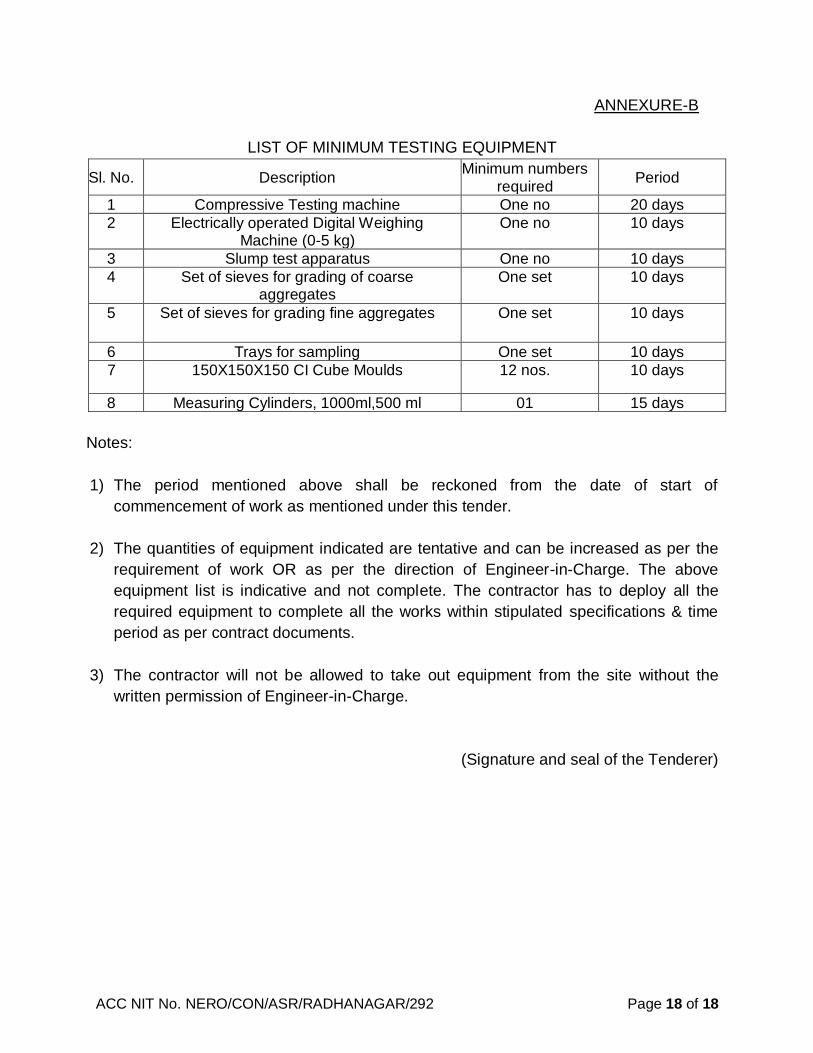


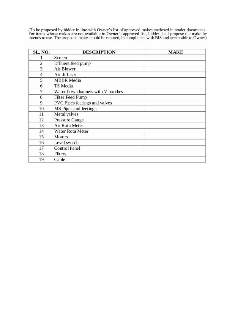


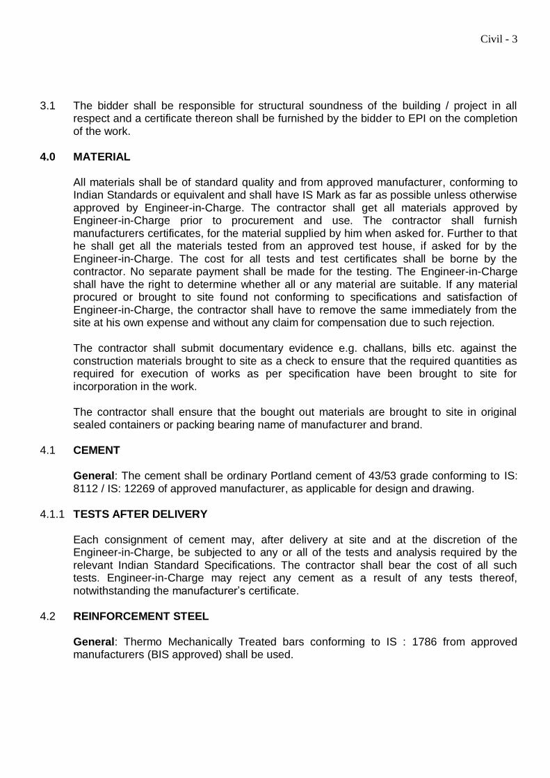


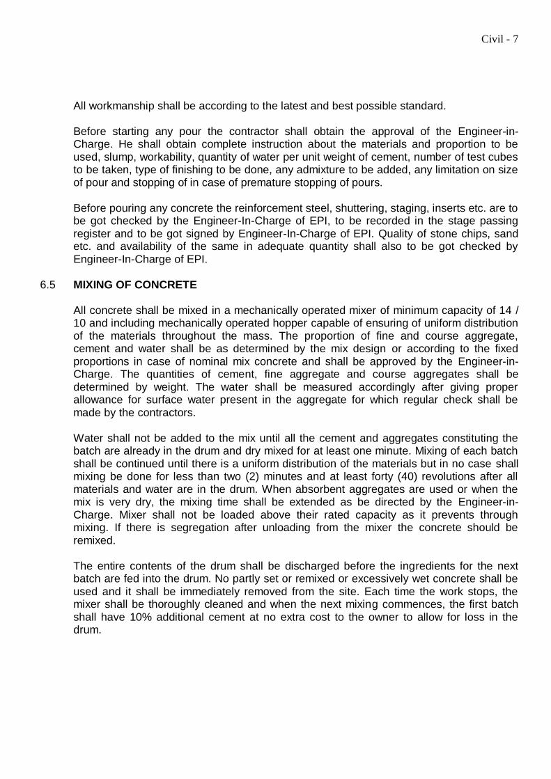


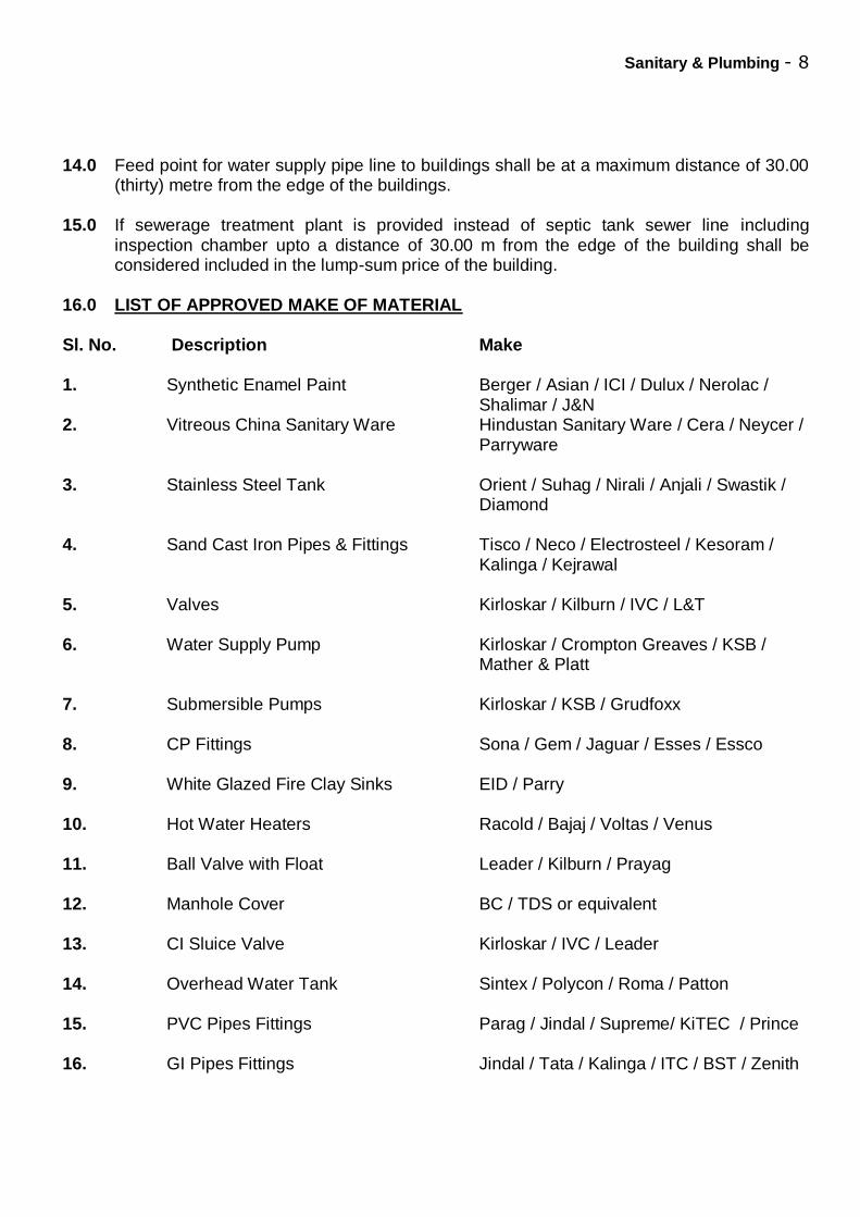


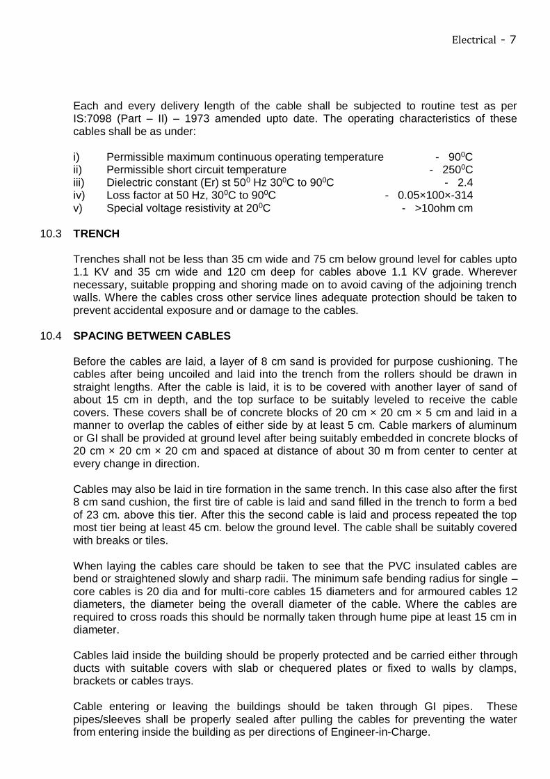

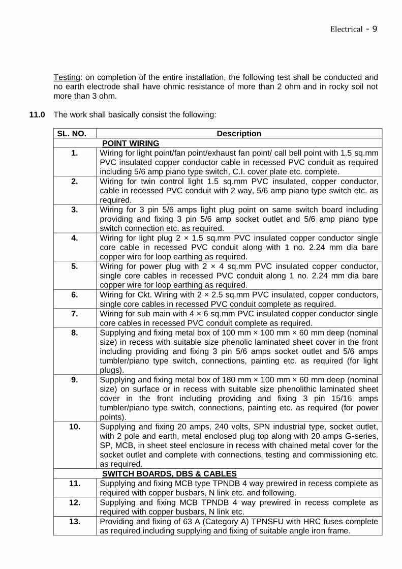
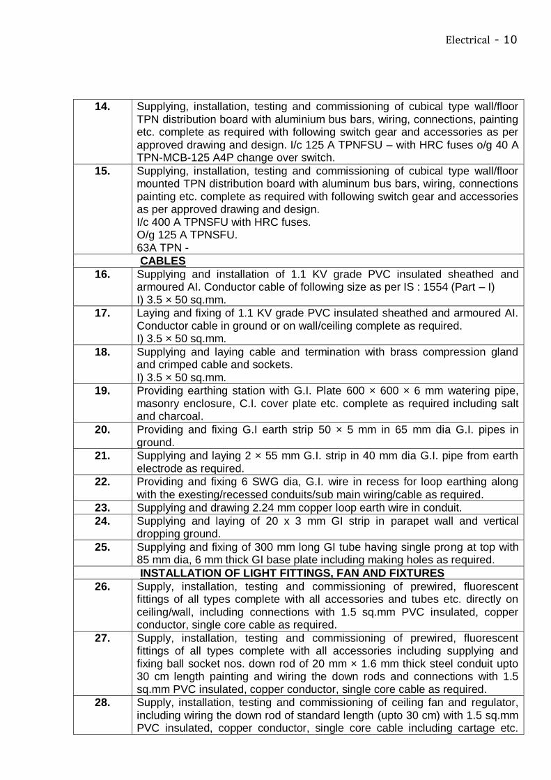


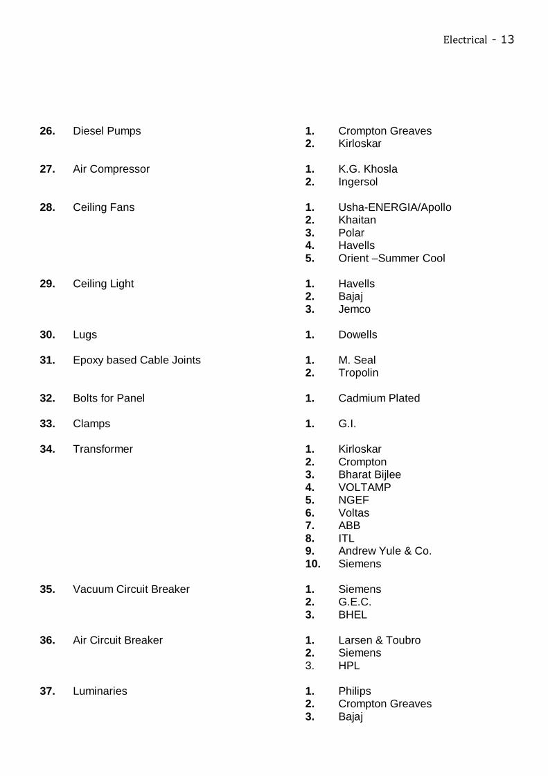


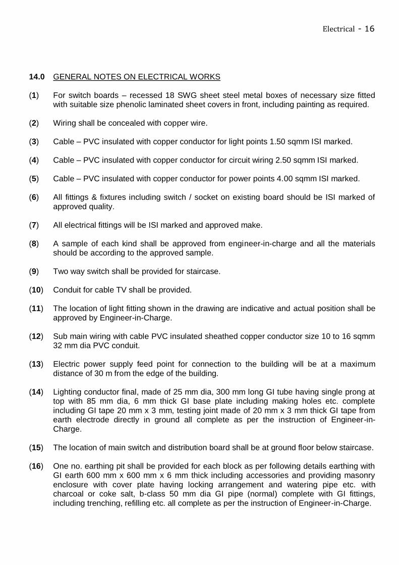


![[PPT]PowerPoint Presentation - University of Delaware 486/Earthwork Notes.ppt · Web viewConstruction Methods & Management CIEG 486-010 Earthwork Earthwork Earthwork Earthwork Earthwork](https://static.documents.pub/doc/80x56/5ab3861f7f8b9ad9788e28f7/pptpowerpoint-presentation-university-of-486earthwork-notespptweb-viewconstruction.jpg)


