28
v1.0 1 Date 24.02.201224/02/2012 Intelligent Infrastructure Track Circuit Monitoring A guide from LNW(N) John Walsh (v1.0)
| Date post: | 22-Dec-2015 |
| Category: |
Documents |
| Upload: | derick-harrell |
| View: | 220 times |
| Download: | 1 times |
v1.0 1
Date 24.02.201224/02/2012
Intelligent InfrastructureTrack Circuit MonitoringA guide from LNW(N)
John Walsh (v1.0)

Date 24.02.2012 v1.0 2
Typical DC Track Circuit Installation
Track relay
Current Sensor
Data Logger
Central Server
Date 24.02.2012 v1.0 3
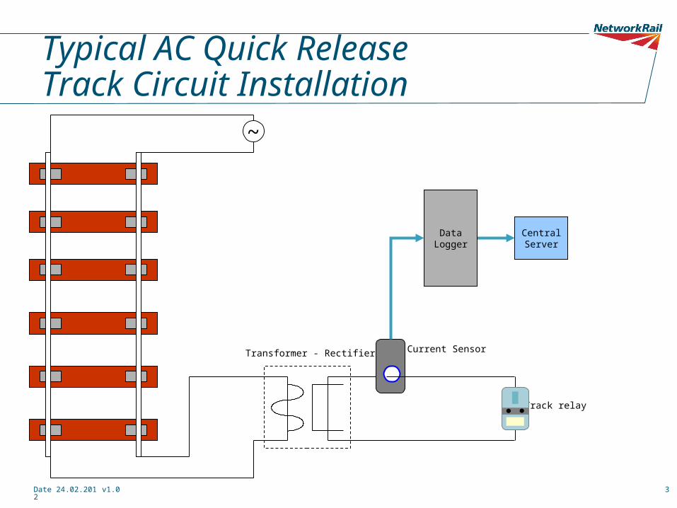
Typical AC Quick Release Track Circuit Installation
Track relay
Current Sensor
Data Logger
Central Server
Transformer - Rectifier
~
Date 24.02.2012 v1.0 4
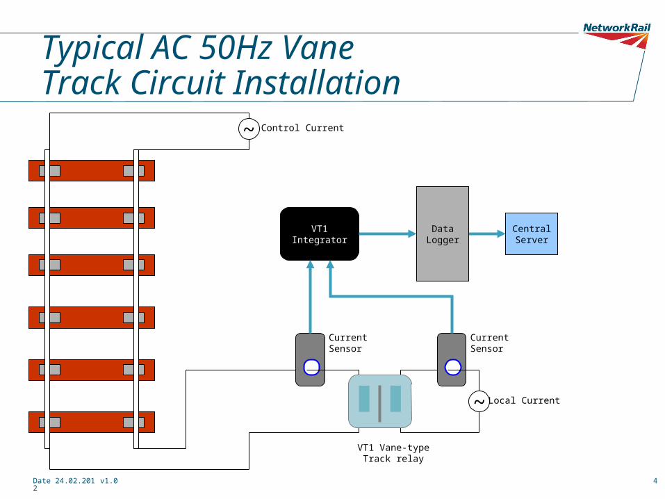
Typical AC 50Hz VaneTrack Circuit Installation
VT1 Vane-type Track relay
Data Logger
Central Server
~ Local Current
Control Current
VT1 Integrator
Current Sensor
Current Sensor
~
Date 24.02.2012 v1.0 5
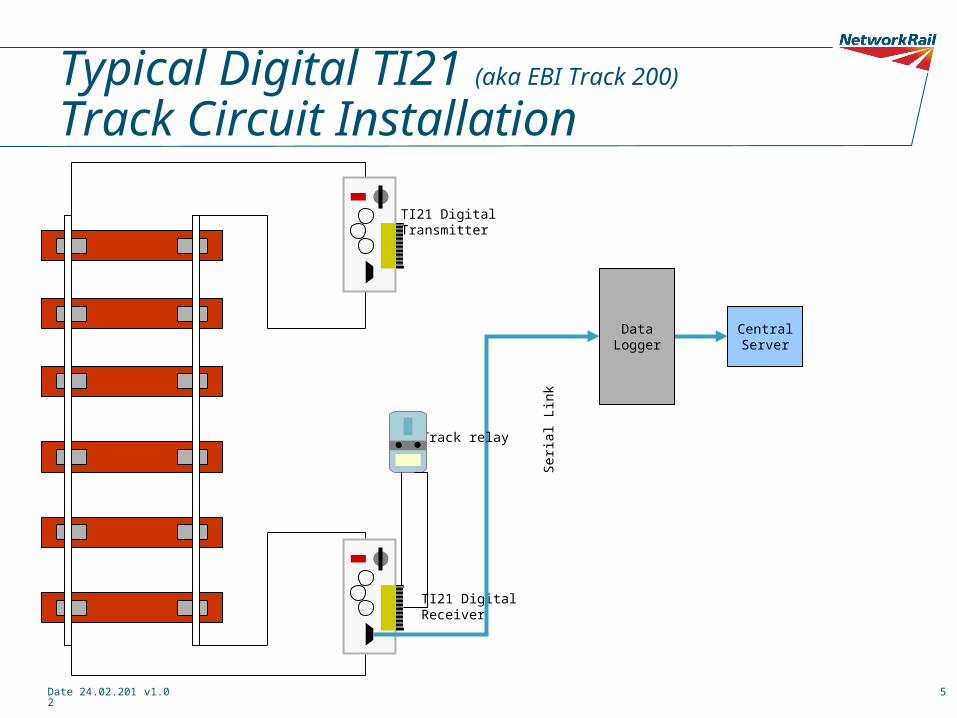
Typical Digital TI21 (aka EBI Track 200)
Track Circuit Installation
TI21 DigitalReceiver
Data Logger
Central Server
Ser
ial L
ink
TI21 Digital Transmitter
Track relay
Date 24.02.2012 v1.0 6
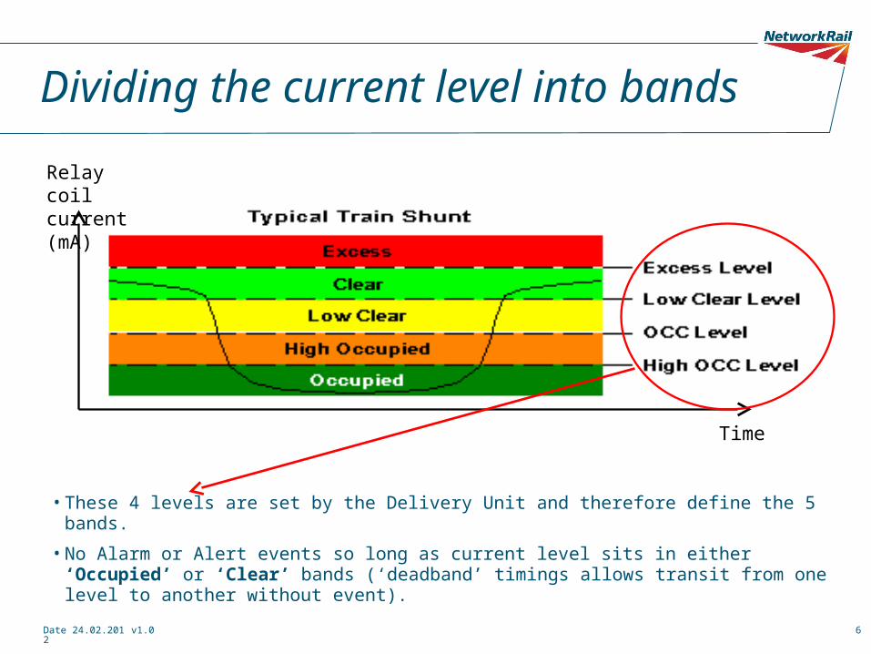
Dividing the current level into bands
• These 4 levels are set by the Delivery Unit and therefore define the 5 bands.
• No Alarm or Alert events so long as current level sits in either ‘Occupied’ or ‘Clear’ bands (‘deadband’ timings allows transit from one level to another without event).
Relay coil current (mA)
Time
Date 24.02.2012 v1.0 7
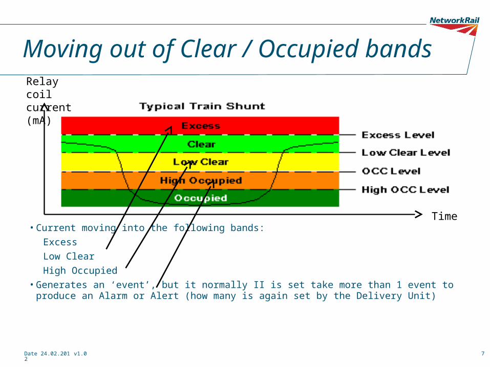
Moving out of Clear / Occupied bands
• Current moving into the following bands: ExcessLow ClearHigh Occupied
• Generates an ‘event’, but it normally II is set take more than 1 event to produce an Alarm or Alert (how many is again set by the Delivery Unit)
Relay coil current (mA)
Time
Date 24.02.2012 v1.0 8
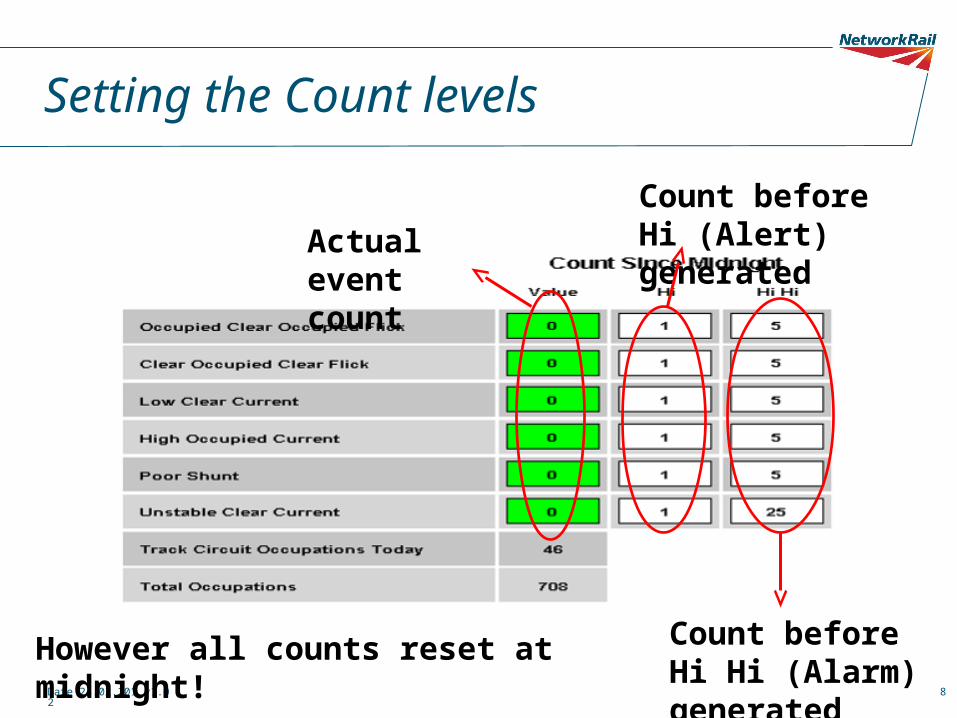
Setting the Count levels
Actual event count
Count before Hi (Alert) generated
Count before Hi Hi (Alarm) generated
However all counts reset at midnight!
Date 24.02.2012 v1.0 9
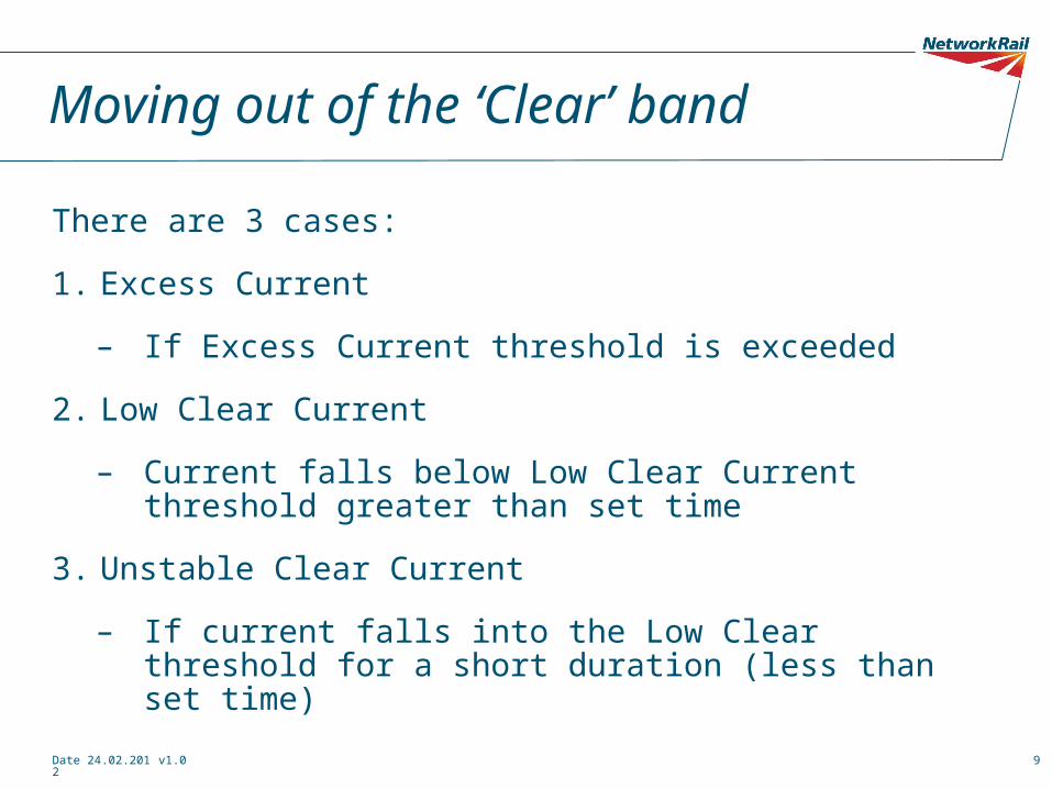
Moving out of the ‘Clear’ band
There are 3 cases:
1. Excess Current
– If Excess Current threshold is exceeded
2. Low Clear Current
– Current falls below Low Clear Current threshold greater than set time
3. Unstable Clear Current
– If current falls into the Low Clear threshold for a short duration (less than set time)

Date 24.02.2012 v1.0 10
Excess current
• Here the current is higher than the Excess Current Limit ( shown by red line)
• No count made on this event – Alert generated (Recorded as priority 3)
• Possible causes – track circuit set for what was poor ballast resistance which has since improved, adjacent (un-staggered) track feed assisting this track etc.

Date 24.02.2012 v1.0 11
Low Clear Current

Date 24.02.2012 v1.0 12
Low Clear Current
Low Clear Level is set to 230mA
Low Clear Deadband set to 2 seconds

Date 24.02.2012 v1.0 13
Low Clear Current
• This event is only generated when transition is made from known good level in Clear band.
• Track circuit current remains in Low Clear band for a duration greater than Low Current-Clear deadband (here it is set to 2s)
• Track circuit current is above Occupied Level but below Low Clear Level.• Possible causes: deteriorating rail insulation pads (pads and nylons), high
resistance tail cables or connections or IBJ failure, salt in level crossing etc
Low Clear Level
Low Clear Level count
Midnight count reset
Date 24.02.2012 v1.0 14
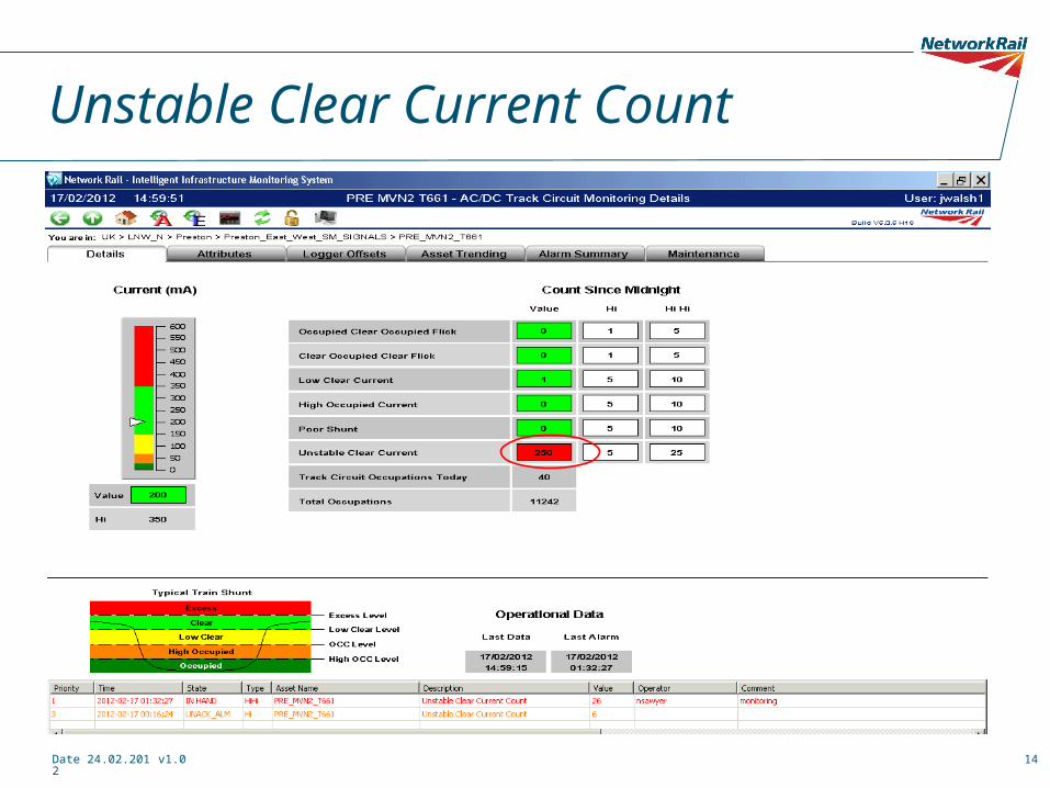
Unstable Clear Current Count
Date 24.02.2012 v1.0 15
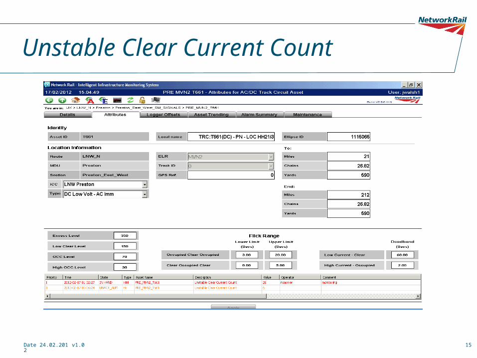
Unstable Clear Current Count

Date 24.02.2012 v1.0 16
Unstable Clear Current Count
• This event is only generated when transition is made from known good level in Clear band but returns back within deadband time
• Track circuit current falls below the Low Clear Current threshold• Causes could be due to intermittent connection (loose track circuit pin,
damaged tail cable, loose back nut etc)
Unstable Clear Current count
Falling below Low Clear Current threshold
Date 24.02.2012 v1.0 17
Unstable Clear Current Count
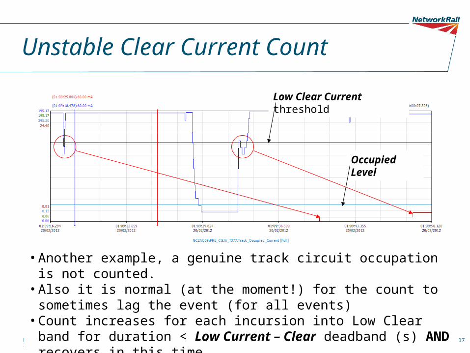
• Another example, a genuine track circuit occupation is not counted.• Also it is normal (at the moment!) for the count to sometimes lag the event
(for all events)• Count increases for each incursion into Low Clear band for duration < Low
Current – Clear deadband (s) AND recovers in this time• This clearly shows the current is unstable - moving rapidly and erratically.
Low Clear Current threshold
Occupied Level
Date 24.02.2012 v1.0 18
Moving out of the ‘Occupied’ band
There are 2 cases of moving out of this band
1.High Occupied Current
–Exceeds High Occupied Current for a set time
2.Poor Shunt
–Exceeds High Occupied Current level for a less than set time (also known as ‘unstable occupied’)
Date 24.02.2012 v1.0 19
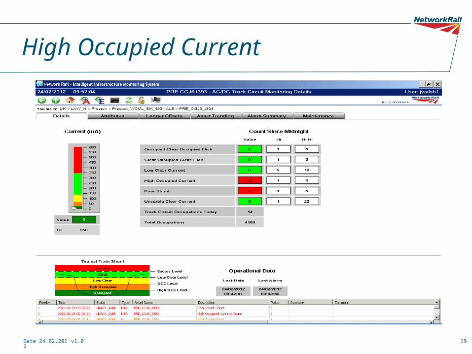
High Occupied Current
Date 24.02.2012 v1.0 20
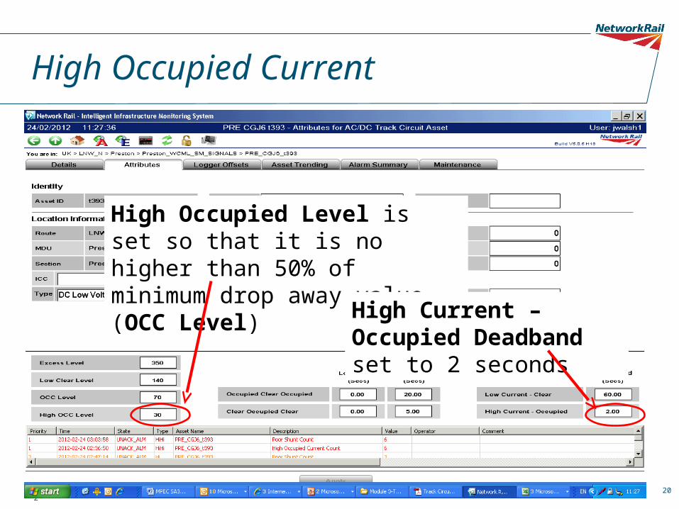
High Occupied Current
High Occupied Level is set so that it is no higher than 50% of minimum drop away value (OCC Level)
High Current – Occupied Deadband set to 2 seconds
Date 24.02.2012 v1.0 21
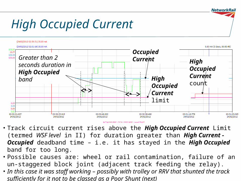
High Occupied Current
• Track circuit current rises above the High Occupied Current Limit (termed WSF level in II) for duration greater than High Current - Occupied deadband time – i.e. it has stayed in the High Occupied band for too long.
• Possible causes are: wheel or rail contamination, failure of an un-staggered block joint (adjacent track feeding the relay).
• In this case it was staff working – possibly with trolley or RRV that shunted the track sufficiently for it not to be classed as a Poor Shunt (next)
High Occupied Current limit
High Occupied Current count
Greater than 2 seconds duration in High Occupied band
Occupied Current
Date 24.02.2012 v1.0 22
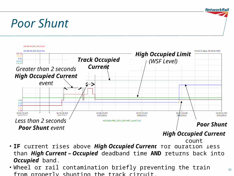
Poor Shunt
Poor Shunt count
Track Occupied CurrentHigh Occupied Limit
(WSF Level)
• IF current rises above High Occupied Current for duration less than High Current – Occupied deadband time AND returns back into Occupied band.
• Wheel or rail contamination briefly preventing the train from properly shunting the track circuit.
High Occupied Current count
Less than 2 seconds Poor Shunt event
Greater than 2 seconds High Occupied Current event

Date 24.02.2012 v1.0 23
Track circuit flicks
• 2 cases:
–Track flick: Clear-Occupied-Clear
–Track flick: Occupied-Clear-Occupied
Date 24.02.2012 v1.0 24
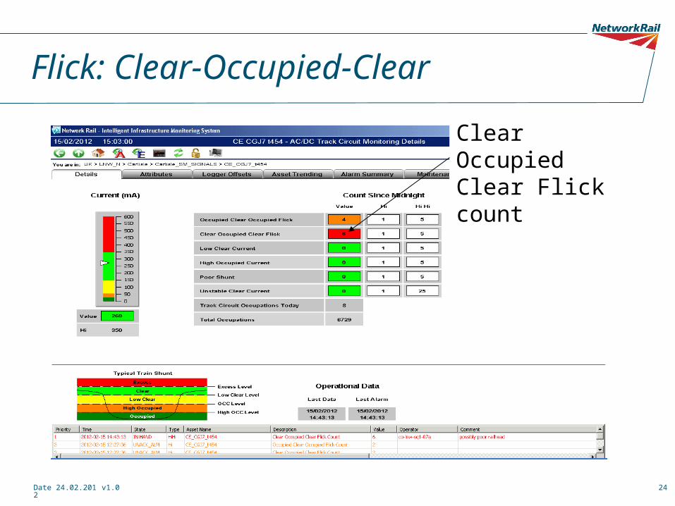
Flick: Clear-Occupied-Clear
Clear Occupied Clear Flick count
Date 24.02.2012 v1.0 25
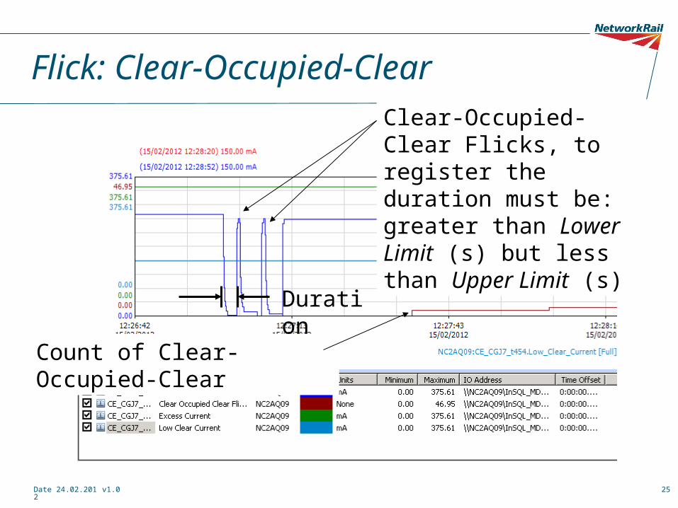
Flick: Clear-Occupied-ClearClear-Occupied-Clear Flicks, to register the duration must be: greater than Lower Limit (s) but less than Upper Limit (s)
Count of Clear-Occupied-Clear
Duration
Date 24.02.2012 v1.0 26
Flicks
• Flicks are basically genuine track clear and occupy events but the duration doesn’t tally with normal operation
• For example if a track circuit occupies for a time less than the fastest and shortest train (with a sensible tolerance) what has caused it? This is counted as a “Clear – Occupied – Clear Flick”.
• Conversely if the track circuit clears whilst is it occupied (“Occupied – Clear – Occupied Flick”) you would certainly want to know about that as it could potentially be a WSF, but there could more subtle reasons especially at the instant the train rolls on and off the track circuit.
Date 24.02.2012 v1.0 27
Processes
• This presentation has focussed on the analysis of track circuits only.
• Success of RCM also depends heavily on our judgment, knowledge, experience and good communication between all parties.
• Be careful not to make the system redundant or insensitive by masking Alarms out or setting wide tolerances.
• Relevant procedures:
– NR/L3/MTC/II0219 [Issue 1] Management of Alerts and Alarms from Remote Condition Monitoring (9 pages)
– NR/L3/OCS/043/3.11 [Issue 2] Response to Remote Condition Monitoring Alarms (3 pages)
– NR/L2/SIG/19811 [ Issue: 3 ] FMS For Network Rail Fault Management (Formerly NR/SP/SIG/19811)

Date 24.02.2012 v1.0 2828
Questions


