2 M Motor Actuators— Y20EBD Valve Linkage for M100 Motor Actuators
M Motor Actuators— Y20EBD Valve Linkage for M100 Motor Actuators 3
lntroduction
The Y20EBD Valve Linkage converts the rotary motion of an M100Series Motor Actuator to a linear movement in order to operate severaltypes of valves.
A rack and pinion drive mechanism provides the linear movement. Therack assembly contains a spring that, when compressed by over travel, willmaintain valve close off to rated values. The pinion gear may be reversedfor manual operation with a 3/8 inch socket drive extension for service ofcontrolled equipment.
Table 1: Selection Table--Actuators and LinkagesLinkageNumber
SpringReturn
Actuator
Non-springReturn
Actuator
Valve Seating Load, lb (n)
Y20EBD-1 M130 M120 75 (334) Green
Y20EBD-2 --- M140 150 (607) Yellow
Y20EBD-3 --- M150 270 (1201) Red
Y20EBD-5 M110 --- 40 (178) Orange
Y20EBD-6 M130 M120 100 (449)
Note: The Y20EBD linkage kit can be used on Barber-Colman1-1/2 to 2 inch valves. Use the grooved adapter bushing providedwith the linkage kit for V-90 Series and the mid-bracket position.Larger Barber-Colman valves can mount onto the Y20EBD yokedirectly; however, adding locally purchased large washers underthe linkage bracket to prevent paint damage is recommended.
A selection of models are available to adapt M100 Motor Actuators toseveral types of valves.
A Y20EBD-4 linkage is available to enable an M150 Motor Actuator tooperate S91 auxiliary switches for automatic heating/cooling changeoverapplications. The Y20EBD-4 allows additional over travel after valveclose off for switch operation. See Y20 Series Linkage Kits ProductBulletin for a complete description.
Y20EBA valve linkage kits are available to adapt the M100 SeriesActuators to valves made by other manufacturers. See Y20 Series LinkageKits Product Bulletin for more information.
Refer to the technical bulletin provided with the motor actuator forinformation on wiring the motor actuator and related adjustments.
ApplicationDetails
4 M Motor Actuators— Y20EBD Valve Linkage for M100 Motor Actuators
The following terminology is used in these instructions:
CW--Clockwise refers to the direction of rotation of the actuator shaft asseen from the load end.
Zero Position--The fully counterclockwise position of the actuatorshaft--the de-energized position of a spring return actuator.
Stem Up--The initial position of the stem is up before operating the valve.
Stem Down--The initial position of the stem is down before operating thevalve.
Push/Drive Down to Open--Pushing or driving the stem down opensthe valve.
Push/Drive Down to Close--Pushing or driving the stem down closesthe valve.
Pull/Drive Up to Open--Pulling or driving the stem up opens the valve.
Pull/Drive Up to Close--Pulling or driving the stem up closes the valve.
Stem Up/Drive Down--The stem is initially in the up position and themotor actuator through the linkage will drive the stem down.
Stem Down/Drive Up--The stem is initially in the down position and themotor actuator through the linkage will drive the stem up.
Three Way Mixing Valve--A valve with two inlets and one outlet. Valveseats on both stem up and stem down travel.
Three Way Diverting Valve--A valve with one inlet and two outlets.Valve seats on both stem up and stem down travel.
Glossary
M Motor Actuators— Y20EBD Valve Linkage for M100 Motor Actuators 5
6 M Motor Actuators— Y20EBD Valve Linkage for M100 Motor Actuators
Upright mounting of the motor actuator is recommended.
When valve mounting, do not mount below the horizontal plane of thevalve piping to prevent damage to the motor actuator if the valve leaks ordevelops condensation.
Do not install the motor actuator in atmospheres with explosive vapors orescaping gases, or where vapors having deteriorating properties mightattack the actuator’s metal parts.
Do not install where the ambient temperature of the surrounding area fallsbelow -40°F (-40°C) for non-spring return motor actuators, or-35°F (-37°C) for spring return motor actuators. The maximum ambienttemperature of the surrounding area of the motor actuator should notexceed 125°F (52°C).
Valve medium temperatures above 250°F (121°C) are permissible only ifthe maximum ambient temperature at the motor actuator is less than 105°F(41°C).
Use insulating washers furnished with the linkage kit for valve mediumtemperature applications over 250°F (121°C).
Locate the motor actuator where the shaft and wiring terminals areaccessible.
The non-spring return M100 Actuator will hold its position if power isremoved. The spring return actuator will return to its zero position ifpower is removed. Both types will hold their current position if thecontrol signal is satisfied.
Note: The spring return is intended only as a safety feature to drive theactuator to its zero position in the event power is interrupted orturned off.
There are three sections to the installation of the Y20EBD valve linkagekit:
1. Configure and mount the yoke on the valve.
2. Mount the actuator and linkage assembly to the yoke and connect tothe valve.
3. Adjust the travel limits to actuate the over travel spring and seat thevalve.
InstallationOverview
M Motor Actuators— Y20EBD Valve Linkage for M100 Motor Actuators 7
The information obtained in the following steps will be used for the traveladjustments later. The reason that these measurements are here is that it iseasier to take the measurements prior to installing the linkage and actuatorthan after.
For valves with various lift requirements, the actuator will require achange in travel by 15° for each additional 0.1 inch (2.54 mm) of liftrequired.
To determine the lift required:
Valve StemFull Up
Valve StemFull Down
Figure 2: Stem Travel Measurement
1. Measure the valve stem length in the full down position as shown inFigure 2.
2. Measure the valve stem length in the full up position as shown inFigure 2.
3. Subtract the full down position from the full up position, this willprovide the valve lift.
4. Divide the valve lift by 0.1 inch.
5. Multiply the result by 15°.
6. Provide additional 15° rotation on 2-way valves and 30° additionalrotation on 3-way valves for over travel seating.
Note: Maximum actuator rotation is 270°, which allows up to 1.7 incheslift on 2-way valves and 1.6 inches lift on 3-way valves.
Note: VT valves have only 5/16 inch lift which requires a reduction ofactuator travel by 25° from factory setting.
Record the value for use with the travel adjustments.
Configurationand Mounting
Valve Lift
8 M Motor Actuators— Y20EBD Valve Linkage for M100 Motor Actuators
When configuring the yoke, two areas have to be considered:
• the distance the actuator will be from the valve (height)
• the direction of drive the actuator is going to provide to the valve
To determine the height:
YokeMountingSurface
Valve StemFull Up
Valve Stem
Full Up
Figure 3: Height Measurement
1. Raise the valve stem to its full up position.
2. Measure from the yoke mounting surface to the top of the stem.
Brackets
Yoke
High
Low
Medium
Y20A1-04
Figure 4: Linkage Bracket Positions
The linkage brackets can be mounted to the yoke in one of three positions:low, medium, or high.
• Low position for stem lengths from 2 inches up to 3 inches(50.8 to 76.2 mm) in full up position. Johnson brass valves up to2 inch (50.8 mm) pipe size.
• Medium position for stem lengths from 3 inches to 4 inches(76.2 to 101.6 mm) in full up position. Johnson iron valves from2-1/2 inches (63.5 mm) pipe size and larger. V90BA valves up to2 inch (50.8 mm) and V90CA valves up to 3 inch (76.2 mm) pipesizes.
Configuring Yoke
Height
M Motor Actuators— Y20EBD Valve Linkage for M100 Motor Actuators 9
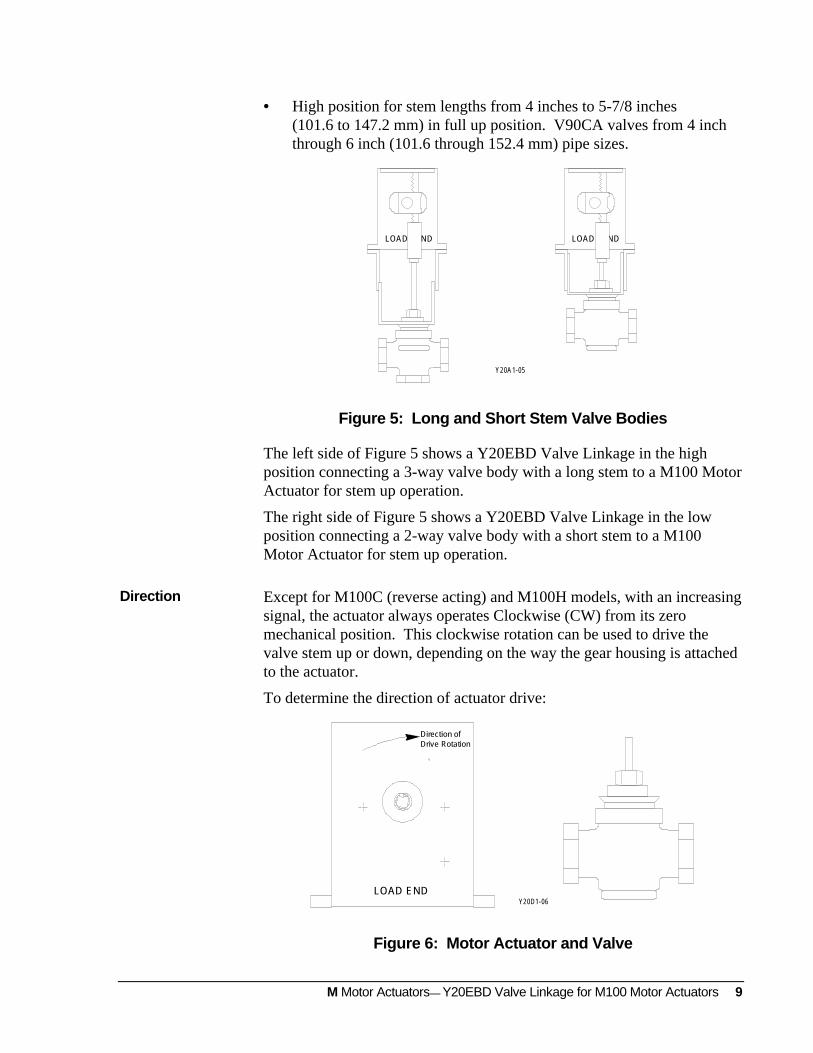
• High position for stem lengths from 4 inches to 5-7/8 inches(101.6 to 147.2 mm) in full up position. V90CA valves from 4 inchthrough 6 inch (101.6 through 152.4 mm) pipe sizes.
LOAD ENDLOAD END
Y20A 1-05
Figure 5: Long and Short Stem Valve Bodies
The left side of Figure 5 shows a Y20EBD Valve Linkage in the highposition connecting a 3-way valve body with a long stem to a M100 MotorActuator for stem up operation.
The right side of Figure 5 shows a Y20EBD Valve Linkage in the lowposition connecting a 2-way valve body with a short stem to a M100Motor Actuator for stem up operation.
Except for M100C (reverse acting) and M100H models, with an increasingsignal, the actuator always operates Clockwise (CW) from its zeromechanical position. This clockwise rotation can be used to drive thevalve stem up or down, depending on the way the gear housing is attachedto the actuator.
To determine the direction of actuator drive:
LOAD END
Direction ofDrive Rotation
Y20D1-06
Figure 6: Motor Actuator and Valve
Direction
10 M Motor Actuators— Y20EBD Valve Linkage for M100 Motor Actuators
1. With the motor actuator next to the valve, view the motor actuatorfrom the load end.
2. Determine the type of valve being used and the direction that will berequired to drive the stem from its initial position.
• Stem Up Two Way Valve--Drive Down to Close
• Stem Up Two Way Valve--Drive Down to Open
• Stem Down Two Way Valve--Drive Up to Open
• Stem Down Two Way Valve--Drive Up to Close
• Stem Up Three Way Valve
• Stem Down Three Way Valve
Load End Load End
Y20A1-07
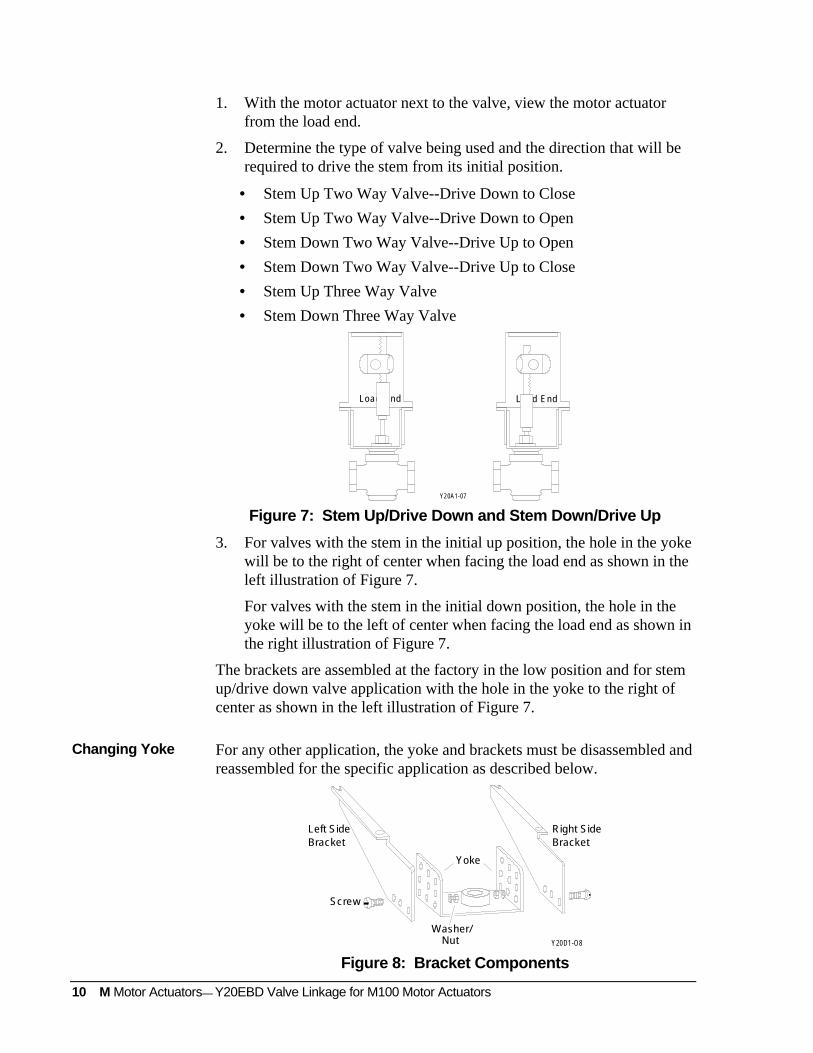
Figure 7: Stem Up/Drive Down and Stem Down/Drive Up
3. For valves with the stem in the initial up position, the hole in the yokewill be to the right of center when facing the load end as shown in theleft illustration of Figure 7.
For valves with the stem in the initial down position, the hole in theyoke will be to the left of center when facing the load end as shown inthe right illustration of Figure 7.
The brackets are assembled at the factory in the low position and for stemup/drive down valve application with the hole in the yoke to the right ofcenter as shown in the left illustration of Figure 7.
For any other application, the yoke and brackets must be disassembled andreassembled for the specific application as described below.
Screw
Left SideBracket
Right SideBracket
NutWasher/
Yoke
Y20D1-O8
Figure 8: Bracket Components
Changing Yoke
M Motor Actuators— Y20EBD Valve Linkage for M100 Motor Actuators 11
1. Remove the screw, washer, and nut securing the left and right sidebrackets to the base bracket.
2. Position the yoke, left side, and right side brackets as determinedpreviously. The pins on the side brackets will fit into the holes in theyoke until the screw is inserted.
3. Install the screw, washer, and nut to secure the side brackets to theyoke and tighten.
Note: The Y20EBD Linkage Kit can be used on Barber-Colman 1-1/2 to2 inch valves. Use the grooved adapter bushing provided with thelinkage kit for V-90 Series and the mid-bracket position. LargerBarber-Colman valves can mount onto the Y20EBD yoke directly;however, adding locally purchased large washers under the linkagebracket to prevent paint damage is recommended.
To mount the yoke on the valve:
Valve
Spr ing Plate
Packing Nut
Yoke Nut
Y20D1-09
Figure 9: Preparing Valve
1. Remove the yoke nut (if present), packing nut (if necessary), andspring plate (if present) from the valve as shown in Figure 9.
Note: Valves with 1/4 inch stems use the furnished yoke nut having a3/4 inch thread to install the bushing and secure the bracket.
Larger valves have a one inch packing box thread on the yokewhich fits the smaller hole bushing and requires a separate yokenut that is usually furnished with the valve.
Mounting Yoke
12 M Motor Actuators— Y20EBD Valve Linkage for M100 Motor Actuators
Valve
Bushing
Yoke Nut
Packing Nut
Jam Nut
Y20D1-10
Figure 10: Mounting Yoke
2. Place the yoke on the valve over the stem and bonnet.
3. Select the proper bushing and slide it over the bonnet and into theyoke hole.
1.01525.78
1.07827 .38
Y20D1-11
Figure 11: Bushings
Note: Two bushings are provided:
• large hole--1.078 in. (27.38 mm) inside diameter which isidentified by a smooth outer edge
• small hole--1.015 inch (25.78 mm) inside diameter which isidentified by a groove on its outer edge
In general, valves up to two inch pipe size have 1/4 inch stems and usethe large hole (no groove) bushing; valves larger than two inch pipesize have 3/8 inch stems and use the small hole bushing (with groove).
4. Install the yoke nut. For valve bodies 2-1/2 inch and larger, use theyoke nut furnished with the valve. Fasten the yoke in place securelyby tightening the yoke nut with a wrench 1/8 turn past finger tight.
5. If the packing nut was removed, reinstall and tighten it. For valveswith U-Cup packing, tighten the nut 1/8 turn past “finger tight.” Forall other valves, tighten finger tight.
Note: JCI valves have U-Cup packing.
M Motor Actuators— Y20EBD Valve Linkage for M100 Motor Actuators 13
6. Install the proper size jam nut onto the valve stem as far as it will go.Do not tighten.
14 M Motor Actuators— Y20EBD Valve Linkage for M100 Motor Actuators
Y20D1-12
Nut
Hex Capscrew
HighTemperature
Washer
M100MotorActuator
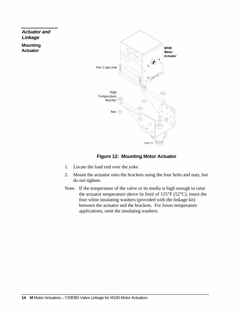
Figure 12: Mounting Motor Actuator
1. Locate the load end over the yoke.
2. Mount the actuator onto the brackets using the four bolts and nuts, butdo not tighten.
Note: If the temperature of the valve or its media is high enough to raisethe actuator temperature above its limit of 125°F (52°C), insert thefour white insulating washers (provided with the linkage kit)between the actuator and the brackets. For lower temperatureapplications, omit the insulating washers.
Actuator andLinkage
MountingActuator
M Motor Actuators— Y20EBD Valve Linkage for M100 Motor Actuators 15
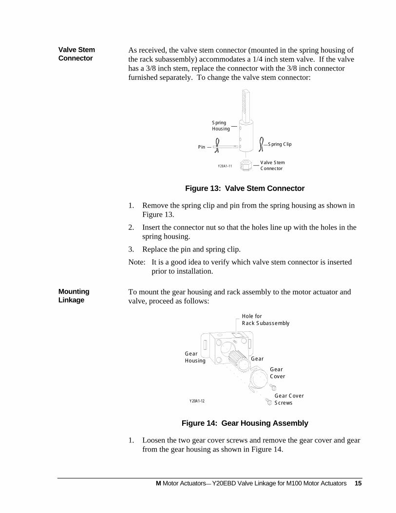
As received, the valve stem connector (mounted in the spring housing ofthe rack subassembly) accommodates a 1/4 inch stem valve. If the valvehas a 3/8 inch stem, replace the connector with the 3/8 inch connectorfurnished separately. To change the valve stem connector:
Spring ClipPin
Valve Stem Connector
SpringHousing
Y20 A1 -1 1
Figure 13: Valve Stem Connector
1. Remove the spring clip and pin from the spring housing as shown inFigure 13.
2. Insert the connector nut so that the holes line up with the holes in thespring housing.
3. Replace the pin and spring clip.
Note: It is a good idea to verify which valve stem connector is insertedprior to installation.
To mount the gear housing and rack assembly to the motor actuator andvalve, proceed as follows:
Y20A1-12
GearHousing Gear
GearCover
Hole forRack Subassembly
Gear CoverScrews
Figure 14: Gear Housing Assembly
1. Loosen the two gear cover screws and remove the gear cover and gearfrom the gear housing as shown in Figure 14.
Valve StemConnector
MountingLinkage
16 M Motor Actuators— Y20EBD Valve Linkage for M100 Motor Actuators
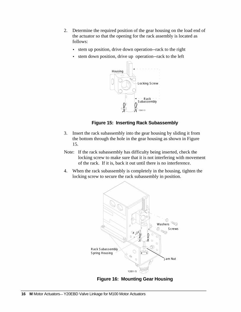
2. Determine the required position of the gear housing on the load end ofthe actuator so that the opening for the rack assembly is located asfollows:
• stem up position, drive down operation--rack to the right
• stem down position, drive up operation--rack to the left
Y20A1-13
Housing
Locking Screw
RackSubassembly
Figure 15: Inserting Rack Subassembly
3. Insert the rack subassembly into the gear housing by sliding it fromthe bottom through the hole in the gear housing as shown in Figure15.
Note: If the rack subassembly has difficulty being inserted, check thelocking screw to make sure that it is not interfering with movementof the rack. If it is, back it out until there is no interference.
4. When the rack subassembly is completely in the housing, tighten thelocking screw to secure the rack subassembly in position.
Jam Nut
Screws
Washers
Rack SubassemblySpring Housing
Y20D1-15
Figure 16: Mounting Gear Housing
M Motor Actuators— Y20EBD Valve Linkage for M100 Motor Actuators 17
5. Position the gear housing and rack subassembly over the valve stemand align the gear housing with the M100 drive shaft.
6. Attach the gear housing to the motor actuator with the washers andgear housing screws. Do not tighten the screws at this time.
7. Loosen the locking screw and lower the rack subassembly to thevalve stem. Thread the rack subassembly spring housing completelyonto the valve stem.
8. Tighten the jam nut (shown in Figure 16) against the stem connector.
9. Align the actuator with the valve body to avoid binding of the linkageand tighten the four mounting bolts.
10. Tighten the screws securing the gear housing to 25 in·lb (2.83 N·m)maximum.
! CAUTION: Do not perform the following operations if the valve isunder pressure. Shut off pump power, includingstandby power, before attempting manual operation.
The procedure for adjusting the travel limits is different for the differentconfigurations of valves:
• Stem Up Two Way Valve--Drive Down to Close Drive down to close,spring return open is the most common configuration for heating.
• Stem Up Two Way Valve--Drive Down to Open
• Stem Down Two Way Valve--Drive Up to Open
• Stem Down Two Way Valve--Drive Up to Close
• Stem Up Three Way Valve
• Stem Down Three Way Valve
! CAUTION: Travel adjustments are made with power connected tothe actuator. On M100A Actuators, alwaysdisconnect power from the actuator before adjustingthe slide stop to increase travel.
Travel Limits
18 M Motor Actuators— Y20EBD Valve Linkage for M100 Motor Actuators
LOAD END
10° (AX)
Direction ofDrive Rotation
COM to CCW Shorted
Drive Shaft
Y20A1-15
KeywayZero Reference Position
Direction of DriveRotation COMto CW Shorted
Figure 17: Actuator Zero Position
The actuators are factory set at zero position which is 10° clockwise fromsquare and for 90° clockwise travel as shown in Figure 17. Each 15° ofactuator rotation results in 0.1 inch (2.54 mm) of linear movement of therack assembly. The 90° actuator rotation provides 1/2 inch (12.7 mm) ofvalve stem lift plus 0.1 inch (2.54 mm) of over travel.
Disconnect all control wires to the actuator. Refer to the technical bulletinprovided with the motor actuator for information on wiring the motoractuator and related adjustments.
Connect only 24 VAC to terminals T1-T2. Be sure that power is off whileconnections are made or changed. For quick reference, Table 2 providesthe connections for individual actuators.
Note: The M100C requires a Y199 tester to drive the motor actuator.
For stem up valves, make certain that the rack is assembled to the right ofthe gear housing center.
Drive Down to Close Valves
1. Manually move the rack and spring housing assembly, connected tothe valve stem, to the full up position.
Y20A1-16
Figure 18: Pinion Gear Ends
2. Insert the pinion gear into the gear housing with the square hole end(Figure 18) over the actuator shaft.
3. Replace the gear cover and tighten the gear cover screws. SeeFigure 14.
Stem Up TwoWay Valve
M Motor Actuators— Y20EBD Valve Linkage for M100 Motor Actuators 19
4. Refer to the technical bulletin provided with the motor actuator andadjust the actuator travel to drive the stem down and compress thespring in the housing (turn power off when adjusting M100A slidestops).
UpperVisualGuide
LowerVisualGuide
ActuatorDrive
Flat Washers
Figure 19: Upper Visual Guide Indicating Full Down Travel
5. As shown in Figure 19, when the edge of the upper flat washer isopposite the notch in the upper visual guide, the travel is properlyadjusted. This represents 0.1 inch (2.54 mm) compression of thespring with the valve seated.
Drive Down to Open Valves
1. Power the actuator to position the actuator 15° from zero. This isequivalent to 0.1 inch (2.54 mm) of stem travel.
2. Manually move the rack and spring housing assembly, connected tothe valve stem, to the full up position.
3. Insert the pinion gear into the gear housing with the square hole overthe actuator shaft.
4. Replace the gear cover and tighten the gear cover screws.
5. Allow the actuator to return to zero position.
UpperVisual
Guide
LowerVisual
Guide
ActuatorDrive
Flat Washers
20 M Motor Actuators— Y20EBD Valve Linkage for M100 Motor Actuators
Figure 20: Lower Visual Guide Indicating Full Up Travel6. As shown in Figure 20, the edge of the lower flat washer should
appear opposite the notch in the lower visual indicator to indicatecompression of the spring with the valve seated.
7. Refer to the technical bulletin provided with the motor actuator andadjust the actuator travel for the full lift as described in the Valve Liftsection.
For stem down valves, make certain that the rack is assembled to the leftof the gear housing.
Drive Up to Close Valves
1. Manually move the rack and spring housing assembly, connected tothe valve stem, to the full down position.
2. Insert the pinion gear into the gear housing with the square hole overthe actuator shaft.
3. Replace the gear cover and tighten the gear cover screws.
4. Refer to the technical bulletin provided with the motor actuator andadjust the actuator travel to drive the stem up and compress the springin the housing (turn power off when adjusting the M100A slide stop).
5. When the edge of the lower flat washer is opposite the notch in thelower visual guide, the travel is properly adjusted. This represents0.1 inch (2.54 mm) compression of the spring with the valve seated.
Drive Up to Open Valves
1. Power the actuator to position the actuator 15° from zero. This isequivalent to 0.1 inch (2.54 mm) of stem travel.
2. Hold the rack in its full down position.
3. Insert the pinion gear into the gear housing with the square hole overthe actuator shaft.
4. Replace the gear cover and tighten the gear cover screws.
5. Allow the actuator to return to zero position. The edge of the upperflat washer should appear opposite the notch in the upper visualindicator to indicate compression of the spring with the valve seated.
6. Refer to the technical bulletin provided with the motor actuator andadjust the actuator travel for full lift as described in the Valve Liftsection.
Stem Down TwoWay Valves
M Motor Actuators— Y20EBD Valve Linkage for M100 Motor Actuators 21
Three way valves, mixing or diverting, can be assembled so that the upperseat is initially closed (stem up) or so that the lower seat is initially closed(stem down). Stem up or stem down operation is determined by the yokeconfiguration and position of the rack and gear housing. Traveladjustments are similar for either case and require both upper and lowerlimits to be set. Both mixing and diverting 3-way valves are adjusted thesame way.
1. Power the actuator to position the drive shaft 15° from zero. This isequivalent to 0.1 inch of stem travel.
2. Manually position the rack to the full stem up or stem down positionas required.
3. Insert the pinion gear into the gear housing with the square hole overthe actuator shaft.
4. Replace the gear cover and screws.
Upper Valve Seat(3-way Valves)
Valve PlugLower Valve
Seat (2-way and3-way Valves)
UpperVisual Guide
For LowerSeat Close Off
LowerVisual Guide
For UpperSeat Close Off
. . . .
. . . .
. . . .
. . . .
. . . .
. . . .
. . . .
. . . .
. . . .
. . . .
. . . .
. . . .
Modulating Lower Seat Closed Upper Seat Closed
Figure 21: Linkage Adjustment Stem Up 3-Way Valve
5. Allow the actuator to return to the zero position. The flat washershould align with the notch at the bottom of the spring case for stemup valves or with the upper notch for stem down valves. Thisindicates valve seating at the zero position.
6. Refer to the technical bulletin provided with the motor actuator andadjust the travel to fully stroke the valve and compress the over travelspring at full lift. The washer should be aligned with the notchopposite the starting point.
7. Figure 21 illustrates the over travel indication for seating stem up3-way valves.
Three Way Valves
22 M Motor Actuators— Y20EBD Valve Linkage for M100 Motor Actuators
! CAUTION: Do not perform this operation if the valve is underpressure. Shut off pump power, including standbypower, before attempting manual operation.
The valve can be manually operated without electrical power whennecessary for maintenance or emergency operation. To operate the valvemanually:
1. Remove the gear cover.
2. Remove the pinion gear from the gear housing and insert the gearwith the square hole facing out.
3. A 3/8 inch socket wrench drive will fit in the square hole and enablemanual positioning of the valve.
4. The spring can be compressed and then held in position by turning thelocking screw (located on the gear housing) in to hold the rack inposition.
IMPORTANT: To return to automatic operation, return the actuator tothe zero position and reinstall the gear with the squarehole engaging the actuator shaft. Repeat the travel limitadjustments as necessary.
Manual Operation
M Motor Actuators— Y20EBD Valve Linkage for M100 Motor Actuators 23
Checkout Procedure
After Installation and adjustment, run the system through several completeopen/close cycles to be sure that all components are functioning correctly.Check to be sure that the actuator responds to the controller and operatesthe valve properly. Check for proper voltage. Check for operation of thelinkage without binding.
! CAUTION: The actuator should not be stalled by the valve. Theactuator may be damaged if it is not free to completeits full stroke.
Table 2: Actuator Connections for Travel Limit AdjustmentJumper Terminals
Model Clockwise (CW) Counterclockwise (CCW)
M100A 1 and 2 1 and 3
M100C COM to CW COM to CCW
M100E S1 to S2* Disconnect S1, S2, A, C
M100F 8 and 9 8 and 10
M100G or M100H 8 to T1 8 to 10
M100J 8 and 9 8 and 10
M100Q 8 to T1 8 to 10
M100M R to B Disconnect R from B
* Apply 24 VAC to relay terminals A and C for clockwise rotation.
Note: On all models, remove controller wires and apply 24 VAC toterminals T1 and T2 while making adjustments. Spring returnmodels will go full CCW when power to T1 and T2 is removed.
24 M Motor Actuators— Y20EBD Valve Linkage for M100 Motor Actuators
Replacement Parts
Table 3 shows replacement parts that may be ordered from your nearestJohnson Controls branch or distributor.
Table 3: Y20 Linkage Repair PartsDescription Code Number Remarks
Gear Assembly GER18A-600 Includes CVR115-1 and GER28-1
270 lb (1201 N) -- used with Y20EBD-3179 lb (796 N) -- used with Y20EBD-4150 lb (667 N) -- used with Y20EBD-275 lb (334 N) -- used with Y20EBD-140 lb (178 N) -- used with Y20EBD-5100 lb (445 N) -- used with Y20EBD-6
* Rack and Spring Housing are an assembly with spring and standard connector (1/4-28)installed. Specify Spring Load for application when ordering.
Table 4: AccessoriesDescription Part Number
5/16 inch Stem Connector Y20EBE-1
VT Adapter Kit Y20EBE-2
M Motor Actuators— Y20EBD Valve Linkage for M100 Motor Actuators 25
Notes
Controls Group507 E. Michigan StreetP.O. Box 423 Printed in U.S.A.Milwaukee, WI 53201