31
V4 Crossing Phase 2 Junction 25 Milton Keynes Western Expansion Area Ringway Phase 2 Feasibility Study B2128801/ FSP/PH2 JUNCTION 25 | 0 17 th December 2015

V4 Crossing Phase 2 Junction 25
Milton Keynes Western Expansion Area
Ringway
Phase 2 Feasibility Study
B2128801/ FSP/PH2 JUNCTION 25 | 0
17th December 2015
Feasibilit y Study Propos al Ringway
Phase 2 Feasibility Study
B2128801/FSP/PH2 J25 rev0 i
V4 Crossing Phase 2 Junction 25, Milton Keynes Western Expansion Area
Project no: B2128801
Document title: Phase 2 Feasibility Study
Document No.: B2128801/FSP/PH2 JUNCTION 25
Revision: 0
Date: 17th December 2015
Client name: Ringway
Client no:
Project manager: Ian Coddington
Author: David Garcia-Cuerva
File name:
Jacobs U.K. Limited
1180 Eskdale Road
Winnersh, Wokingham
Reading RG41 5TU
United Kingdom
T +44 (0)118 946 7000
F +44 (0)118 946 7001
www.jacobs.com
© Copyright 2015 Jacobs U.K. Limited. The concepts and information contained in this document are the property of Jacobs. Use or copying of
this document in whole or in part without the written permission of Jacobs constitutes an infringement of copyright.
Limitation: This report has been prepared on behalf of, and for the exclusive use of Jacobs’ Client, and is subject to, and issued in accordance with, the provisions of the
contract between Jacobs and the Client. Jacobs accepts no liability or responsibility whatsoever for, or in respect of, any use of, or reliance upon, this report by any third party.
Document history and status
Revision Date Description By Review Approved
0 17/12/2015 1st issue DGC CD IC
Phase 2 Feasibility Study
B2128801/FSP/PH2 J25 rev0 ii
Contents
1. Introduction ................................................................................................................................................ 1
1.1 General ........................................................................................................................................................ 1
1.2 Study area and objective ............................................................................................................................. 1
1.3 Approach ..................................................................................................................................................... 2
2. Background Information ........................................................................................................................... 3
2.1 Information Gathered................................................................................................................................... 3
2.2 Design Criteria / Standards ......................................................................................................................... 4
2.3 Design assumptions .................................................................................................................................... 7
2.4 Information Used For Design Drawings ...................................................................................................... 4
3. Feasibility Assessment ............................................................................................................................. 5
3.1 Location ....................................................................................................................................................... 5
3.2 Option Selection .......................................................................................................................................... 5
3.3 Feasibility study limitations .......................................................................................................................... 6
4. Key Risks ................................................................................................................................................... 8
5. Recommendations and further works ..................................................................................................... 9
5.1 Recommendations ....................................................................................................................................... 9
5.2 Further works, investigation and surveys .................................................................................................... 9
6. References ............................................................................................................................................... 11
6.1 Ordnance Survey Mapping ........................................................................................................................ 11
Appendix A. Gap Analysis
Appendix B. Site constraints plan
Appendix C. Concept Drawing
Appendix D. Section A-A
Appendix E. CDM Designers Risk Assessment
Appendix F. Project Risk Register

Phase 2 Feasibility Study
B2128801/FSP/PH2 J25 rev0 1
1. Introduction
1.1 General
In July 2015 Jacobs UK Ltd was commissioned by Ringway to carry out a feasibility study for a new subway in
Milton Keynes, for Milton Keynes Council (MKC). The proposed subway will link the planned Western
Expansion Area 10 (WEA 10) Redway routes on the south side of the V4 Watling Street to the existing (MKC)
routes on the north side of the road.
Feasibility Report B2128801/FSP/JUNCTION 25 issued 04/09/2015, discussed the feasibility of crossings
located either side of Junction 25. Further works identified in section 5.2 of the above report, included the
requirement to carry out pedestrian and cyclist surveys to confirm desire lines. A review of the desire lines has
consequently been conducted by UDLA who stated that the proposed subway crossings were sited too far away
from the desire lines and should be brought closer to the roundabout to aid the transition of pedestrians across
the V4.
MKC discussed the cost variance of constructing so close to the roundabouts and stated that a further feasibility
was required to ascertain the differences of Cost/Benefits/Constraints. This report discusses the feasibility of a
V4 crossing adjacent to the Junction 25 roundabout.
1.2 Study area and objective
Prior to this study, an approximate crossing location was identified by the client, east of and as close to the
Junction 25 roundabout as possible, but further work was required to understand the site constraints and fix the
subway position.
The key objective of this report is to provide an alternative concept option for cost benefit analysis compared
with options presented in Phase 1 to determine the most suitable location for the subway to allow the project to
progress to preliminary and detailed design phases, and ultimately to construction.
The approximate location of Junction 25 roundabout is highlighted on the mapping extract below:
Fairways Roundabout
Crownhill Roundabout
Western Expansion
Area 10
J25
Phase 2 Feasibility Study
B2128801/FSP/PH2 J25 rev0 2
1.3 Approach
Our approach has been to locate a subway crossing to a suitable position taking into consideration the desire
lines confirmed by the UDLA, the main constraints such as the existing topography and road layout, the position
of the existing and future Redways routes, the existing utilities, the existing highway boundary and any other
relevant information that could influence the selection process (e.g. existing highways improvement at junction
25). As part of this study the following steps were carried out:
• Existing data review, gap analysis and constraints identification
• Option generation and assessment
• Site visit and Client Meeting
• Concept design of the preferred option
1.4 Deliverables
The following drawings and documents have been prepared as part of this report:
• Gap Analysis – provided in Appendix A
• Site Constraints Plan - (Drawing No. B2128801-J25-0004) – provided in Appendix B
• Concept General Arrangement - (Drawing No.B2128801-J25-0005) – provided in Appendix C
• Section A-A - (Drawing No.B2128801-J25-0006) – provided in Appendix D
• CDM Designers Risk Assessment – provided in Appendix E
• Risk Register – provided in Appendix F

Phase 2 Feasibility Study
B2128801/FSP/PH2 J25 rev0 3
2. Background Information
2.1 Information Gathered
The following historic information has been provided by MKC and Ringway:
• MKC Standards, including details for Redways and Footways
• Existing topographical survey data
• C2 Statutory records
• Details of proposed new utility company services
• Trench reports from ground investigation works
• Designs for the WEA 10 housing development being constructed by Gallagher’s
• Archaeology information
• Borehole records
• Details of ‘Lessons Learnt’ from a previous scheme (Pinch point scheme)
• Previous MKC scheme drawings
• Ecology reports
Further to the above the Jacobs project team conducted a site visit on the 7th December 2015.
A gap analysis was carried out on the above supplied data and subsequently missing data. Results of this gap
analysis are provided in Appendix A.
A review of the above supplied data was undertaken and used to produce a constraint plan to inform this
feasibility study. The constraint plan is provided in Appendix B.
Phase 2 Feasibility Study
B2128801/FSP/PH2 J25 rev0 4
2.2 Design Criteria / Standards
The Milton Keynes Council (MKC) design brief provided specific design requirements; the following are the
relevant ones at this feasibility stage:
• The client specified the use of ABM Europe to fabricate the modular subway, with the chosen
construction method being pre-formed standard design modular sections.
• Internal dimensions of the subway structure are; minimum of 8.5m in width and 2.7m in height from
finished surface level.
• Sight distances of 4.0m should be provided at corners and changes of direction. To determine visibility
requirements pedestrians are to be assumed to be 0.4m away from an adjacent vertical wall. Inside
corners are to be rounded off to a radius of 4.6m to meet this requirement.
• Use of Milton Keynes Council standard details for Redways and footways.
In addition to the above requirements, Design Manual for Roads and Bridges (DMRB) TD 36/93 (Subways for
Pedestrians and Pedal Cyclists Layout and Dimensions) was used to design the subway layout.
2.3 Information Used For Design Drawings
In following information sources were used in the development of Design Options and Design drawings:
Supplied by MKC;
� “Redway table.dwg” – Location of Redway
� Ordnance survey Information
� “Watling_3D.dwg” – Topographical survey information
� “Adopted Highways.dwg” – Highways Boundary
� “MKS UG services.dwg” – Location of services taken from Historic C2 enquiries
� “Junctions.dwg” – Location of proposed Junction 25
Supplied by Gallaghers MK;
� WEA master Plan drawing
Jacobs project team site visit;
� Approximate location of Culvert and Swales
� Approximate location of 3 new Gas Chambers
� Approximate location of 5m wide Attenuation Pond
Phase 2 Feasibility Study
B2128801/FSP/PH2 J25 rev0 5
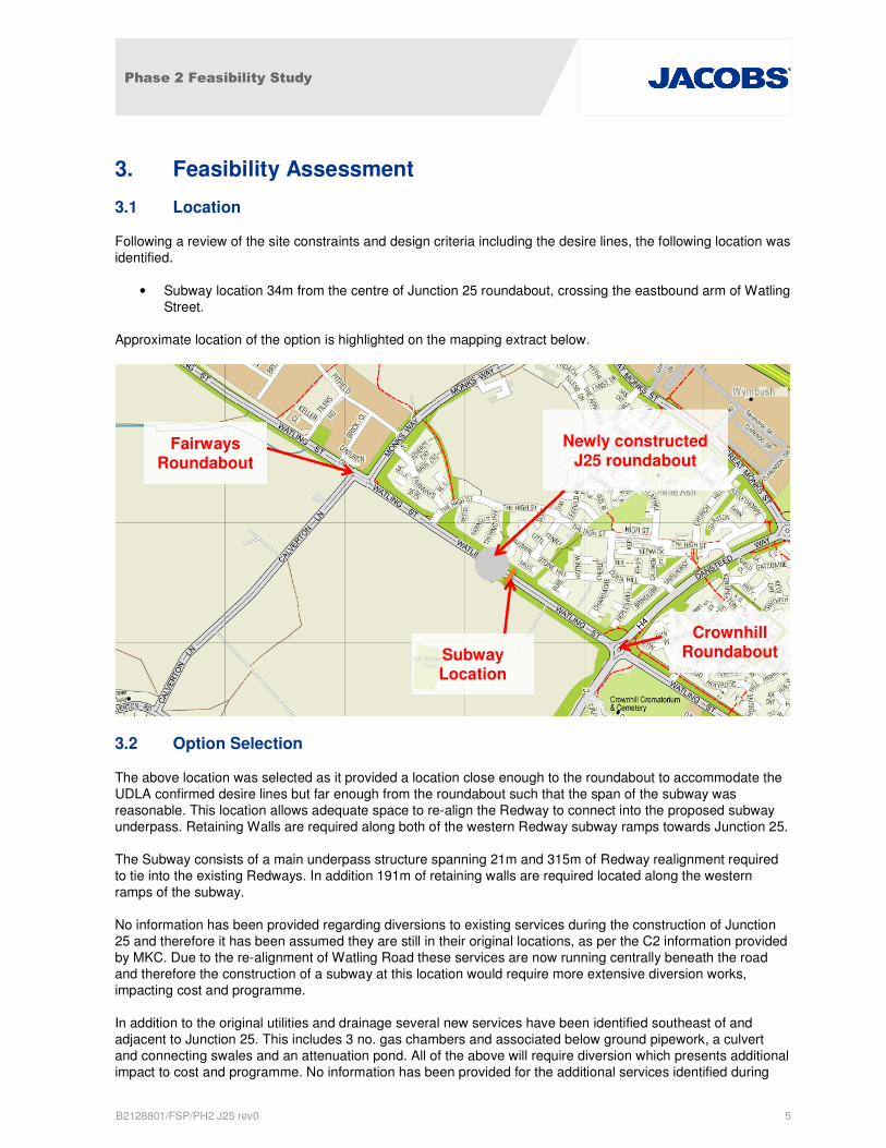
3. Feasibility Assessment
3.1 Location
Following a review of the site constraints and design criteria including the desire lines, the following location was
identified.
• Subway location 34m from the centre of Junction 25 roundabout, crossing the eastbound arm of Watling
Street.
Approximate location of the option is highlighted on the mapping extract below.
3.2 Option Selection
The above location was selected as it provided a location close enough to the roundabout to accommodate the
UDLA confirmed desire lines but far enough from the roundabout such that the span of the subway was
reasonable. This location allows adequate space to re-align the Redway to connect into the proposed subway
underpass. Retaining Walls are required along both of the western Redway subway ramps towards Junction 25.
The Subway consists of a main underpass structure spanning 21m and 315m of Redway realignment required
to tie into the existing Redways. In addition 191m of retaining walls are required located along the western
ramps of the subway.
No information has been provided regarding diversions to existing services during the construction of Junction
25 and therefore it has been assumed they are still in their original locations, as per the C2 information provided
by MKC. Due to the re-alignment of Watling Road these services are now running centrally beneath the road
and therefore the construction of a subway at this location would require more extensive diversion works,
impacting cost and programme.
In addition to the original utilities and drainage several new services have been identified southeast of and
adjacent to Junction 25. This includes 3 no. gas chambers and associated below ground pipework, a culvert
and connecting swales and an attenuation pond. All of the above will require diversion which presents additional
impact to cost and programme. No information has been provided for the additional services identified during
Subway Location
Newly constructed J25 roundabout
Fairways Roundabout
Crownhill Roundabout

Phase 2 Feasibility Study
B2128801/FSP/PH2 J25 rev0 6
the 07/12/2015 site visit and so it is not possible to fully assess the impact they have on the proposed concept
design.
Following agreement to develop the selected option, further design works were undertaken to produce Concept
design for the subway. Additional as built data for the newly constructed Junction 25 and trench surveys at the
proposed subway location were requested, however they could not be sourced by MKC within a reasonable
timeframe to be considered. It was therefore agreed that rather than delay the project further, the concept
design should progress based on the information available.
Option concept design is included in Appendix C, Section A-A included in Appendix D and designer risk
assessment in Appendix E
3.3 Feasibility study limitations
All design work has been based on the data provided by Ringway and Milton Keynes Council. These were
assumed to be satisfactory and no verification works were carried out as part of this commission.
Topographical survey was historic and out of date in places.
The utilities records and data provided were historic and out of date in places.
As built information was not supplied for the new Junction 25 roundabout and the existing surface water
drainage network.
Highway Boundary data for the new development was not supplied.
It was also assumed that the impacted utilities along Watling Street will be raised and diverted to a 2m wide side
verges. This will be subject to agreement with the statutory undertakers. At this stage no contact were made to
engage formally the statutory undertakers.
During the site visit on 07/12/2015 it was noted, a number of new gas chambers and pipework has been
installed southeast of the Junction 25 roundabout, for which no information has been provided.
Additional drainage features have also been constructed at the new Junction 25 roundabout including
attenuation pond, culvert and swales. No as built information has been provided.
The Phase 1 brief highlighted the possibility of an asbestos cement water main. No further investigations or
asbestos survey were carried out as part of this feasibility study to locate/identify the presence of the asbestos
water main.
This feasibility study did not cover drainage issues or structural design, which are to be dealt with at a later
stage of the scheme development. The use of ABM fabricated modular subway structured units is specified, but
ABM design criteria are yet to be confirmed. The structures are designed to comply with Design Manual for
Roads and Bridges (DMRB) standards.
Landscaping issues and lighting provision were not covered as part of this study and will be addressed at a later
stage of the scheme development.
No information was provided regarding ground investigations (water levels, land contamination, pavement
construction or California Bearing Ratio).
Land outside of the highway boundary will be dealt with as part of Section 38 work, which is outside the scope
of this study.
Construction cost estimate was not provided as it was outside the scope of this study.

Phase 2 Feasibility Study
B2128801/FSP/PH2 J25 rev0 7
3.4 Design assumptions
All design work has been based on the data provided by Ringway and Milton Keynes Council. These were
assumed to be satisfactory and no verification works were carried out as part of this commission.
1 in 2 slopes were assumed at this stage pending confirmation following geotechnical investigations. This
provided the benefit of minimising the earthworks footprint and keeping the proposal within the highway
boundary. Where this is not possible retaining walls will be utilised.
1 in 20 slopes were used to design the access ramps, however, landings were not provided as instructed by
MKC as these would create a “take off point” for cyclists. This is non-compliant with design standards (TD 36/93
– section 5.5) states that landings should be included for changes in elevation greater than 3.5m, which the
proposed subway will have.
It was also assumed that impacted utilities will be raised and diverted to a 2m wide side verge either side of the
road to maintain the 900mm cover above the subway. This will be subject to agreement with the statutory
undertakers. The brief also highlighted the possibility of an asbestos cement water main. No evidence was
provided of its presence; therefore it was assumed that the asbestos water main is not present. This assumption
will need to be confirmed at later stage.
It was assumed that land outside of the highway boundary will be dealt with as part of Section 38 work, which is
outside the scope of this study.
The gas chambers and associated pipework, culvert and associated swales and attenuation pond identified
during a site visit on 7th of December will be affected by the proposed option. No information has currently been
provided at this stage. Therefore for this report it has been assumed that they can all either be relocated or
diverted.
This feasibility study does not cover drainage issues or structural design, which are to be dealt with at a later
stage of the scheme development. It was assumed that ABM Europe modular subway structure will be used
and a system of pump and pipes will be required to assist with surface water drainage. It was also assumed that
the ground water level (GWL) is not a concern. No GWL information is available and this assumption will need
to be confirmed.

Phase 2 Feasibility Study
B2128801/FSP/PH2 J25 rev0 8
4. Key Risks
Following completion of the Feasibility Study, the main project risks are considered to be:
• Gaps in the current project data – Results of additional surveys/information provided could be
unfavourable and lead to design changes with cost and programme impact. Collection of data may also
lead to programme delays.
• Service diversions are required – This will be subject to agreement with the statutory undertakers, could
increase the project cost and may have programme implications.
• ABM design is specified. ABM design criteria’s are yet to be confirmed. Also to be confirmed is that
these structures are designed to Eurocode. This could lead to departures from standards with cost and
programme implications.
• There has been no liaison with the Technical Approval Authority (TAA) for the proposed structure. The
requirements that the TAA may advise as regards to the design and check category in the Approval in
Principal (AIP) could impact on the programme.
• Archaeology is a potential risks and so is the coordination with an external Ecology consultant. Both
could impact on cost and programme.
• Three gas chambers were identified during a site visit on the 7th December 2015. These are located just
below the south quadrant of the Junction 25 roundabout. The relocation or diversion the gas chambers
and associated pipework is likely to be required impacting project cost and programme. It is not possible
to determine the impact without further information.
• An attenuation pond, existing culvert and swales along the south of Watling Street were identified during
a site visit on the 7th
December 2015. No information has been provided regarding the drainage
infrastructure in place at this location. The relocation of these drainage features will be required for the
new subway structure. It is not possible to determine the impact without further information.
• Ecology Impacts are unknown and could impact the proposed design affecting project cost and
programme
The project Risk Register has been updated following the Feasibility Study and is provided in Appendix F.

Phase 2 Feasibility Study
B2128801/FSP/PH2 J25 rev0 9
5. Recommendations and further works
5.1 Recommendations
Based on the analysis of site constraints including the desire lines, site visits and discussion with Milton Keynes
Council to ensure local knowledge was taken into consideration, the proposed Subway location 34m east of
Junction 25, was deemed the most feasible location to meet the client brief. This location minimises deviation
from the desire lines stated in the UDLA report and also minimises the associated costs of constructing a longer
subway underpass closer to Junction 25.
To enable the project to develop further, the project team will require more information. Additional data required
has been identified and listed below in section 5.2. It is recommended that the Client seeks to commission
additional surveys as soon as possible to avoid project delays.
Early liaison with stakeholders, including utility companies, is recommended to ascertain an early response with
regards to proposed service diversions.
It is also recommended that further preliminary design works be undertaken, with greater consideration given to
highways, structural and drainage design issues. This will enable an initial estimate of construction costs.
Jacobs have provided a proposal for preliminary and detailed design works for the project.
5.2 Further works, investigation and surveys
Further works are required to confirm our assumptions in section 2.3 and resolve the limitations highlighted in
section 3.3. The list below identifies the relevant investigation / surveys necessary to inform the design process.
This list is not exhaustive and could change depending on findings as the design progresses:
• Topographical survey showing the newly constructed Junction 25 roundabout.
• Trial Hole/trench survey at the proposed subway location.
• As built records of the existing drainage and highway networks affected are also required.
• Geotechnical investigations are required to confirm the use of 1 in 2 slopes, suggest likely foundation
design for the structure and highlight any contamination if present.
• Utilities mapping of the study area is required to identify impacted utilities. This will also help when
engaging the affected statutory undertakers, which should be done as early as possible to avoid
unnecessary delays and costs due to diversions.
• The Phase 1 brief highlighted the possibility of an asbestos cement water main. Further investigation is
required to locate and if applicable carry out an asbestos survey.
• Carry out a drainage survey to confirm location and drainage requirements for Culvert associated
swales and Attenuation Pond identified on site. Details of existing ground water levels are required.
• Conduct a Survey of the Gas Chambers identified during the site visit on 7th December 2015 to confirm
the exact location of the Chambers and associated pipework. Also commence liaison with statutory
undertakers to gain an early response regarding the possibility of diversion.
• Highway Boundary details for new development are required
• Approval for Departure from TD 36/93 to omit the need for landings.
• Progress the structural design and confirm suitability of ABM modular subway.

Phase 2 Feasibility Study
B2128801/FSP/PH2 J25 rev0 10
• Liaison with Technical Approval Authority (TAA) for structural design Approval in Principal (AIP)
• Ecology appraisal and subsequent surveys as required
Phase 2 Feasibility Study
B2128801/FSP/PH2 J25 rev0 11
6. References
6.1 Ordnance Survey Mapping
Mapping used within this report and the drawings provided in the appendices is reproduced from Ordnance
Survey material with the permission of the Ordnance Survey on behalf of the Controller of Her Majesty’s
Stationary Office © Crown copyright and database rights 2015 OS [100019593]. Unauthorised reproduction
infringes Crown copyright and may lead to prosecution or civil proceedings.

Phase 2 Feasibility Study
B0000000 FSP
Appendix A. Gap Analysis
Comment
no.
Discipline By Date raised Comment
1 Highways DG 29/07/2015 Missing info about utilities in the northbound verge of the Watling Street
2 Highways PT 30/07/2015 No survey information north of existing Redway (north of Watling Street)
3 Highways PT 30/07/2015 C2 info from Virgin indicates something in Northern Redway
4 Highways PT 30/07/2015 C2 info from Cable and Wireless indicates something in Northern Redway
5 Highways PT 30/07/2015 C2 info from BT Openreach is very basic. Some corrupted files. Indicates
ducting in northern Redway - nothing on GPR. Indicates ducting in southern
verge, GPR shows 4 separate groups of ducts totalling 13 No. 100 dia. No
mention of Fibre Optic cables. No accurate location, size & depth information
except as shown in Trench Report.
6 Highways PT 30/07/2015 C2 Street Lighting information is corrupted. Have assumed location on south
verge, based on GPR survey information based on Trench Report
8 Highways PT 30/07/2015 C2 info relating to Asbestos Cement Water Main sketchy, No accurate
location, size & depth information except as shown in Trench Report.
9 Highways PT 30/07/2015 C2 info from Western Power relates to north of Watling Street only
10 Highways PT 30/07/2015 MKC XREF 19723.dwg.is large but has 20 No. unreferenced and not available
utilities xrefs. GPR results not consistent with Trench Report
11 Highways PT 30/07/2015 MKS UG Services.dwg taken from 19723, but reduced to suit Developer’s
needs.
12 Highways PT 30/07/2015 MKS UG Services (JJG amended).dwg taken from 19723, but reduced to suit
Developer’s needs. (lots of unnecessary hatching)
13 Highways PT 30/07/2015 Approved design for Junction 25 required.
THE NOTES ABOVE RELATE TO JUNCTION 25 SUBWAY PHASE 1 OPTIONS, BUT ALSO RELATE TO JUNCTION 25 SUBWAY
PHASE 2 OPTIONS
14 Highways DG 02/11/2015 Topo survey supplied by MKC is not up to date; therefore it does not include
the recent completion of the J25 roundabout and associated earthworks.
15 Highways DG 30/11/2015 No available further C2 information following completion of Junction 25.
Assumed the ducts have not been re-aligned with the Junction.

Phase 2 Feasibility Study
B0000000 FSP
16 Highways DG 10/12/2015 Following a site visit on 07/12/2015, a new gas chamber has been installed on
the south side of Watling Street adjacent to Junction 25. No information is
available regarding the gas chamber and any related pipe/ductwork.
17 Highways DG 10/12/2015 Following a site visit on 07/12/2015, a new culvert and swales have been
installed either side of J25 on the southern side of Watling Street. No survey
information has been provided for these.
18 Highways DG 10/12/2015 Following a site visit on 07/12/2015 an attenuation pond was identified in the
proximity of the south quadrant of the Junction 25. No information is available
regarding the attenuation pond.
19 Highways IC 17/12/2015 No Highway Boundary information for development south of Junction 25.

Phase 2 Feasibility Study
B0000000 FSP
Appendix B. Site constraints plan

Phase 2 Feasibility Study
B0000000 FSP
Appendix C. Concept Drawings

Phase 2 Feasibility Study
B0000000 FSP
Appendix D. Section A-A

Phase 2 Feasibility Study
B0000000 FSP
Appendix E. CDM Designers Risk Assessment
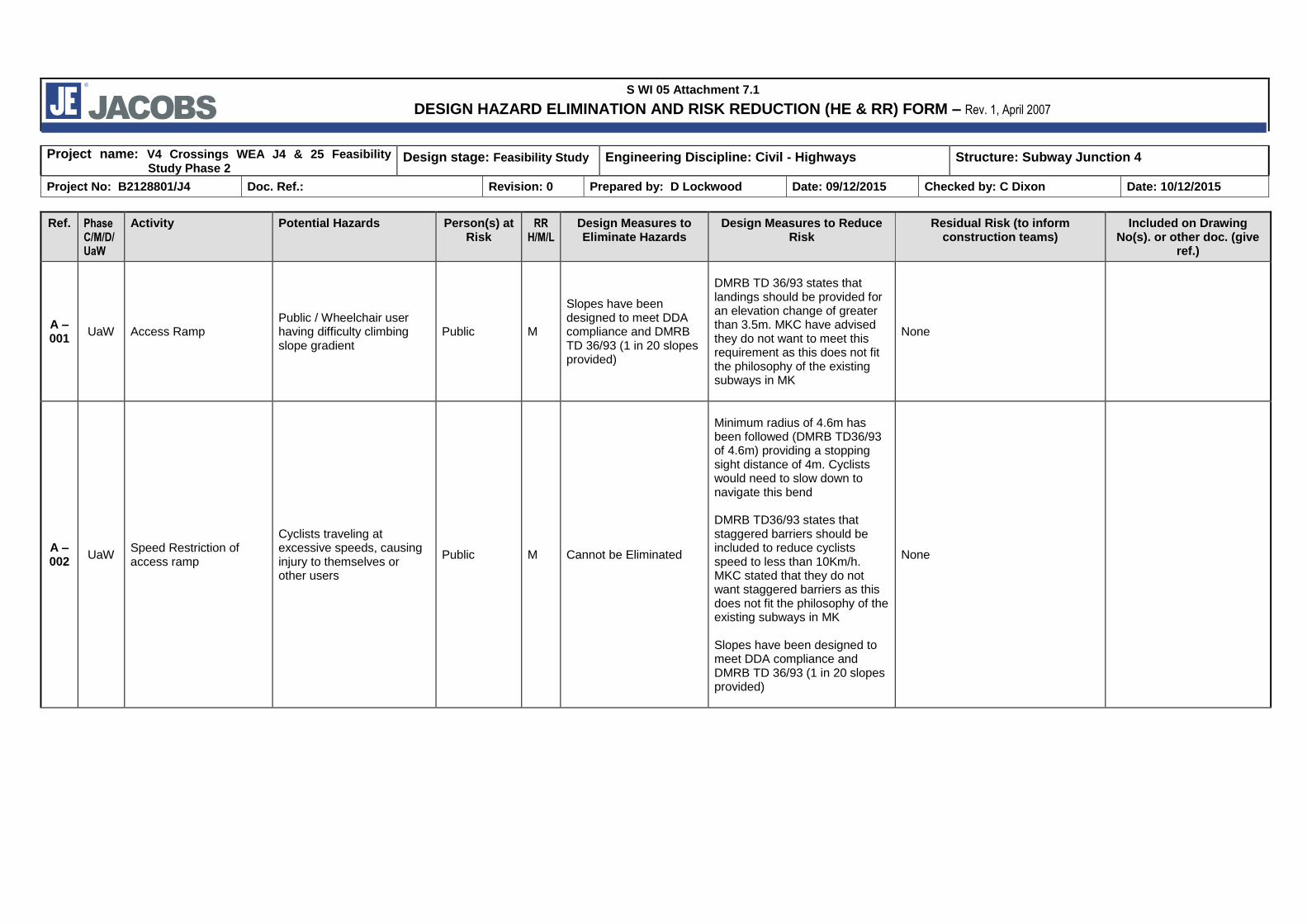
S WI 05 Attachment 7.1
DESIGN HAZARD ELIMINATION AND RISK REDUCTION (HE & RR) FORM – Rev. 1, April 2007
Project name: V4 Crossings WEA J4 & 25 Feasibility Study Phase 2
Design stage: Feasibility Study Engineering Discipline: Civil - Highways Structure: Subway Junction 4
Project No: B2128801/J4 Doc. Ref.: Revision: 0 Prepared by: D Lockwood Date: 09/12/2015 Checked by: C Dixon Date: 10/12/2015
Ref. Phase C/M/D/UaW
Activity Potential Hazards Person(s) at Risk
RR H/M/L
Design Measures to Eliminate Hazards
Design Measures to Reduce Risk
Residual Risk (to inform construction teams)
Included on Drawing No(s). or other doc. (give
ref.)
A – 001
UaW Access Ramp Public / Wheelchair user having difficulty climbing slope gradient
Public M
Slopes have been designed to meet DDA compliance and DMRB TD 36/93 (1 in 20 slopes provided)
DMRB TD 36/93 states that landings should be provided for an elevation change of greater than 3.5m. MKC have advised they do not want to meet this requirement as this does not fit the philosophy of the existing subways in MK
None
A – 002
UaW Speed Restriction of access ramp
Cyclists traveling at excessive speeds, causing injury to themselves or other users
Public M Cannot be Eliminated
Minimum radius of 4.6m has been followed (DMRB TD36/93 of 4.6m) providing a stopping sight distance of 4m. Cyclists would need to slow down to navigate this bend DMRB TD36/93 states that staggered barriers should be included to reduce cyclists speed to less than 10Km/h. MKC stated that they do not want staggered barriers as this does not fit the philosophy of the existing subways in MK Slopes have been designed to meet DDA compliance and DMRB TD 36/93 (1 in 20 slopes provided)
None
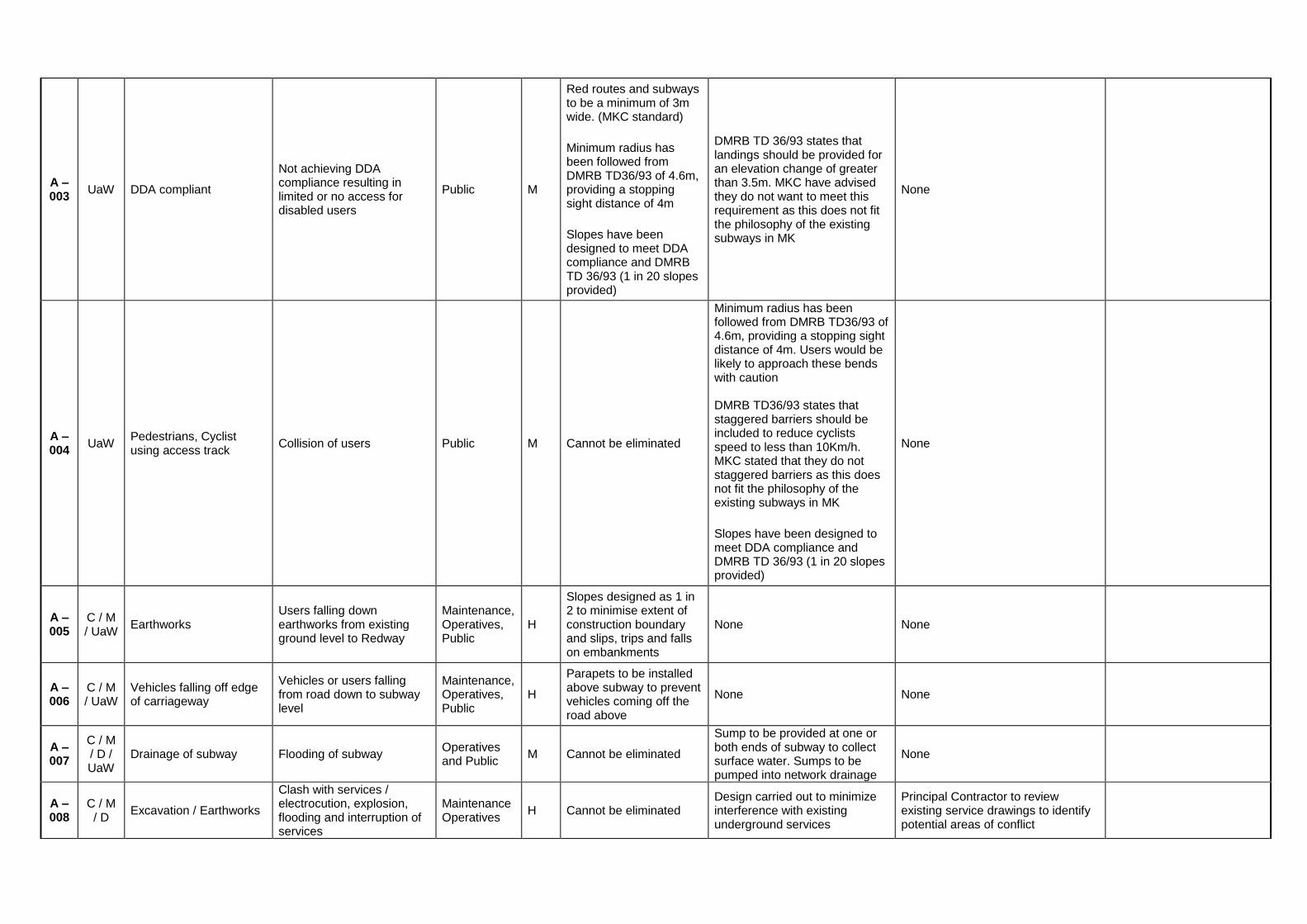
A – 003
UaW DDA compliant
Not achieving DDA compliance resulting in limited or no access for disabled users
Public M
Red routes and subways to be a minimum of 3m wide. (MKC standard)
Minimum radius has been followed from DMRB TD36/93 of 4.6m, providing a stopping sight distance of 4m
Slopes have been designed to meet DDA compliance and DMRB TD 36/93 (1 in 20 slopes provided)
DMRB TD 36/93 states that landings should be provided for an elevation change of greater than 3.5m. MKC have advised they do not want to meet this requirement as this does not fit the philosophy of the existing subways in MK
None
A – 004
UaW Pedestrians, Cyclist using access track
Collision of users Public M Cannot be eliminated
Minimum radius has been followed from DMRB TD36/93 of 4.6m, providing a stopping sight distance of 4m. Users would be likely to approach these bends with caution DMRB TD36/93 states that staggered barriers should be included to reduce cyclists speed to less than 10Km/h. MKC stated that they do not staggered barriers as this does not fit the philosophy of the existing subways in MK
Slopes have been designed to meet DDA compliance and DMRB TD 36/93 (1 in 20 slopes provided)
None
A – 005
C / M / UaW
Earthworks Users falling down earthworks from existing ground level to Redway
Maintenance, Operatives, Public
H
Slopes designed as 1 in 2 to minimise extent of construction boundary and slips, trips and falls on embankments
None None
A – 006
C / M / UaW
Vehicles falling off edge of carriageway
Vehicles or users falling from road down to subway level
Maintenance, Operatives, Public
H
Parapets to be installed above subway to prevent vehicles coming off the road above
None None
A – 007
C / M / D / UaW
Drainage of subway Flooding of subway Operatives and Public
M Cannot be eliminated
Sump to be provided at one or both ends of subway to collect surface water. Sumps to be pumped into network drainage
None
A – 008
C / M / D
Excavation / Earthworks
Clash with services / electrocution, explosion, flooding and interruption of services
Maintenance Operatives
H Cannot be eliminated Design carried out to minimize interference with existing underground services
Principal Contractor to review existing service drawings to identify potential areas of conflict

A – 009
C / M / D
Excavation / Earthworks Working in close proximity to Gas Chamber and Pipeline
Operatives H Cannot be eliminated Cannot be reduced
Contractor to undertake inspections to confirm pipeline location prior to works. Ensure appropriate PPE and material storage is provided
A – 010
C / M / D
Excavation / Earthworks Disturbance/work in close proximity to Asbestos Cement Pipelines
Operatives H Cannot be eliminated Cannot be reduced
Contractor to conduct trial holes at proposed location to confirm the presence of asbestos, and ensure appropriate PPE and material storage/removal procedures in place
A – 011
C / M / D
Excavation / Earthworks Contaminated land Maintenance Operatives
M Cannot be eliminated Cannot be reduced Contractor to undertake GI prior to works and ensure appropriate PPE and material storage is provided
A – 012
C / M / UaW
Working adjacent to live traffic
Risk to drivers, general public, cyclists and workforce from conflict during construction
Operatives, Public
M
MKC have confirmed that a full road closure including the red route will be undertaken during construction. Therefore removing this risk.
None
Principal Contractor’s Traffic Management measure to be deployed in accordance with Chapter 8 of the traffic signs manual by a competent contractor
A – 013
UaW Using subway at night / low light conditions
Unable to use subway due to limited lighting at night time/ increased risk of collision/trips from users
Public M Lighting in the subway to be provided
None None
A – 014
C / M / UaW
Concurrent site activities from various contractors
Risk to operatives and public from uncoordinated works with other contractors leading to injury
Operatives, Public
M Cannot be eliminated Subway and earthworks has been designed to minimise construction boundary
Principal Contractor to liaise with MKC and developers on adjacent sites to co-ordinate programme/works
A – 015
C / D Lifting of ABM modular units
Lifting of ABM modular units Operatives M Cannot be eliminated
Lifting plan to be produced.
ABM modular units to have lifting hooks or lifting points.
Correcting lifting strapping to be use as per lifting plan.
Principal Contractor to review lifting plan, TM plan and ensure units are providing with lifting points
A – 016
C / M / D
Excavation / Earthworks Working in close proximity to substation
Operatives H Cannot be eliminated
Cannot be reduced at present. Further works recommended establishing cable locations. Once known design is to be amended to reduce impact
Contractor to undertake inspections to confirm cable location prior to works. Ensure appropriate PPE and material storage is provided
Phase Severity of Injury Probability (Prob.) Risk Rating (RR) Hierarchy of Mitigation
C = Construct H: Major, Fatal or long term disabling injury or illness. H: Highly likely
Pro
b.
(LM
H) M H H Note – the purpose of Risk Rating is
to determine which risks are significant. It is a subjective process,
not an absolute or precise determination.
1. Eliminate hazard (design out)
M = Maintain / Clean M: Moderate injury or illness M: Likely event L M H 2. Reduce risk at source (amend design)
D = Demolish and/or Adapt L: Minor injury/ illness L: Possible L L M 3. Provide risk information (add to design)
UaW Use as Work[place
Severity (LMH)

Phase 2 Feasibility Study
B0000000 FSP
Appendix F. Project Risk Register

Phase 2 V4 Crossing J25 & V4 Crossing J4
Milton Keynes Western Expansion Area
Project Risk Register
Rev3 11/12/15
B0000000 FSP2
Risk Likelihood (A) 1-5
Impact (B) 1-5
Risk Rating = AxB
Max 25 Min 1
Mitigation Plan Owner Revised Likelihood
(C) 1-5
Mitigated Risk
Rating
Technical
Gaps in current project data. Results of additional surveys/information provided could be unfavourable and lead to design changes. Collection of data may lead to programme delays
3 5 15 Feasibility study has identified additional surveys/investigations required for future design phases through gap analysis. Actual site investigations to be commissioned by Ringway. Assumptions made due to limited/inadequate data to be clearly stated in deliverables. Deliverables to include design risk and design issues logs
Jacobs / Ringway / MKC
1 5
Service diversions are required. This will require liaison with service providers, will increase the project cost and may have programme impact
5 4 20 Feasibility study has identified anticipated service diversions MKC to undertake early engagement with service providers Regular stakeholder engagement, Jacobs & Ringway to provide input where required
MKC 5 10
At J4 service diversion may be required for the new 900mm water main maintained by Anglian Water (AW), should AW not agree to the retaining wall solution. This will increase the project cost and may have programme impact
3 5 15 Issue identified during Feasibility Study Cross section showing proposed retaining wall option supplied to MKC to facilitate discussion with AW MKC engaging with AW at early stage to mitigate programme delay and understand potential cost if diversion is required
MKC 2 10
ABM design is specified but may be unsuitable. This could lead to departures from design being required
3 5 15 Standards have been used for other similar structures and has been specified by MKC Assumption included in proposal that standards will be suitable Jacobs to provide early warning should standard design found not be suitable
MKC 1 5
Data on utility company services is not available, or is incorrect leading to significant design changes.
4 5 20 Feasibility study has identified additional data required through gap analysis and provided opportunity for early engagement with Ringway for them to provide data via Trench
Ringway / MKC 4 5

Phase 2 V4 Crossing J25 & V4 Crossing J4
Milton Keynes Western Expansion Area
Project Risk Register
Rev3 11/12/15
B0000000 FSP2
Surveys and GPR. Responsibility for accuracy and purpose of data supplied by others is not to be carried by Jacobs. Additional data for surface water drainage requested by MKC
Brief is not detailed enough. Deliverables do not meet client expectations
2 5 10 Early and regular engagement with both Ringway and MKC to confirm expectations. Better understanding through completion of Feasibility Study Design phase start-up meetings to be combined with site visits PM to undertake CES at project outset Jacobs to confirm understanding of requirements via proposal and raise queries in timely fashion Brief is to work to existing and documented standards. Jacobs team to undertake site visit to similar, already built structure to confirm understanding
Jacobs 1 5
GI factual & interpretative report delivery is currently scheduled outside programme milestones for preparation of design: impacts on programme.
5 3 15 Mitigate by commencing foundation design on assumptions in advance of GI report, subject to MKC carrying risk of any abortive design. Alternatively manage risk by accepting programme delay.
MKC 1 3
No archaeological watching brief during Ground Investigation works. Archaeological feature is found during works, leading to programme delays
2 4 8 Query raised at tender stage by Jacobs MKC stated that there was info contained within the Appendices to the briefs re. archaeology. Email in Appendices 02 states ‘No significant archaeology was found in the areas of investigation directly adjacent to the indicated locations and as such do not envisage any archaeological work as being required. Caveat included in proposal based on this assumption.
MKC 2 8
Results of additional surveys such as GI, topographical
2 5 10 Subway locations have been identified by client
Jacobs / Ringway / MKC
1 5

Phase 2 V4 Crossing J25 & V4 Crossing J4
Milton Keynes Western Expansion Area
Project Risk Register
Rev3 11/12/15
B0000000 FSP2
survey etc. are unfavourable, leading to design changes
Large amount of existing data gives confidence that locations are suitable Feasibility study has identified gaps in data. Ringway to arrange surveys in a timely fashion, such that survey data/results can be incorporated into the design Caveat included in proposal based on assumption that results are not unfavourable leading to significant re-design/abortive works.
Access not supplied for surveys. Design is required to proceed on the basis of assumptions, or delay to programme
2 4 10 Feasibility study has identified gaps in data and should provide adequate time for access to be arranged Feasibility Study has identified majority of scheme will be within MKC owned land so limited engagement required MKC to arrange access. MKC already engaging stake holders Caveat included in proposal based on this assumption
Jacobs / Ringway / MKC
1 4
At J4 one proposed location of subway (phase 2 feasibility, option B) will require diversion of AW 900mm pipe unless redway ramp is steeper than standards (approximately 1 in 11 rather than standard of 1 in 20). This will lead to non-compliance with DDA standards
3 5 15 Issue identified during Feasibility Study phase 2 General Arrangement prepared at request of MKC to highlight issue MKC engaging with AW at early stage to mitigate programme delay and understand potential cost if diversion is required or level of protection AW required MKC to provide confirmation of departure from standard if option is progressed
MKC 2 10
At J4 Feasibility Study phase 2 options impact existing at grade Redway crossing of Miller’s Way. This will require diversion, non-standard ramp slopes or potentially an additional subway under Miller’s Way to maintain current crossing/Redway route
4 5 20 Issue identified during Feasibility Study phase 2 General Arrangement prepared at request of MKC to highlight issue MKC to consider when determining how project is to progress
MKC 2 10

Phase 2 V4 Crossing J25 & V4 Crossing J4
Milton Keynes Western Expansion Area
Project Risk Register
Rev3 11/12/15
B0000000 FSP2
Gas Chamber and related pipe/ductwork installed on the south side of Watling Street adjacent to Junction 25 identified during site visit on 07/12/15 but not on supplied information. Potential clash with design option – lack of survey information.
3 4 12 Feasibility study phase 2 has identified additional surveys/investigations required for future design phases through gap analysis. MKC to undertake early engagement with service providers Regular stakeholder engagement, Jacobs & Ringway to provide input where required.
Jacobs / Ringway / MKC
2 8
Existing culvert on the WEA development approach to Junction 25 discharging into ditches running parallel to the Watling Street identified during site visit on 07/12/15 but not on supplied information. May need diversion.
5 2 10 Feasibility study phase 2 has identified additional surveys/investigations required for future design phases through gap analysis. Confirmation of Culvert location, level and construction details required to determine if diversion/relocation is required in future design phase.
Jacobs / Ringway / MKC
3 6
Attenuation Pond located in the south quadrant of the Junction 25 identified during site visit on 07/12/15 but not on supplied information, has potential to clash/impact with design.
5 2 10 Feasibility study phase 2 has identified additional surveys/investigations required for future design phases through gap analysis. MKC to provide Drainage information. Regular stakeholder engagement, Jacobs & Ringway to provide input where required. Relocation of Pond may be required.
Jacobs / Ringway / MKC
3 6
Sub-station has been installed on the north side of Watling Street adjacent to Junction 4, identified during site visit on 07/12/15 but not on supplied information. Potential clash with design - No information available regarding sub-station and any related pipe/ductwork.
3 4 12 Feasibility study phase 2 has identified additional surveys/investigations required for future design phases through gap analysis. MKC to undertake early engagement with service providers Regular stakeholder engagement, Jacobs & Ringway to provide input where required.
Jacobs / Ringway / MKC
3 6
Client Satisfaction
Failure to manage expectations of external stakeholders in terms of outputs of the study
3 3 9
Key stakeholders identified prior to project start up (Parks Trust, Milton Keynes Urban Design), and agreed with end client (MKC) Ongoing liaison with the external
Jacobs / Ringway / MKC
1 3

Phase 2 V4 Crossing J25 & V4 Crossing J4
Milton Keynes Western Expansion Area
Project Risk Register
Rev3 11/12/15
B0000000 FSP2
stakeholders via regular meetings and communications. MKC to determine when in project programme stakeholder engagement should take place. MKC already in contact with ley stakeholders
Change in scope/ programme / cost resulting in poor client perception of the deliverables
3 3 9
Regular client meetings, including key design discipline leads, Project Manager and stakeholders Regular update of risk register Regular progress reports to project team and client Regular progress meetings with project team PM to ensure early warning regarding any issues pertaining to scope, programme, cost or quality
Jacobs / Ringway 1 3
Programme
Data requested such as surveys, ground investigations data, is not supplied within timescales required for project, leading to assumptions in design or programme delays
3 5 15
Feasibility study has identified gaps in data Timely preparation of scope documents by Jacobs Ringway have supply chain for GI, utility survey and topographical survey works
Jacobs / Ringway 2 10
Issues arising from public consultation require significant/time consuming design changes which affect the programme; Delays in responses from consultation lead to subsequent programme delay
2 4 8
Client has stated that public consultation is considered as information sharing exercise only There is public support for the scheme and it is widely recognised that the subways are required. Assumptions included in proposal and factored into programme regarding timeframe for responses Jacobs requested by MKC to provide attendance at key meetings/consultation to assist with presentation of scheme
MKC 1 4
Client/MKC fail to make timely decisions regarding project
2 4 8 Ringway / MK / LLFA to clarify decision makers and confirm in ToR
Jacobs / Ringway / MKC
1 4

Phase 2 V4 Crossing J25 & V4 Crossing J4
Milton Keynes Western Expansion Area
Project Risk Register
Rev3 11/12/15
B0000000 FSP2
issues, leading to project delays/abortive works
Regular client meetings, including key design discipline leads, Project Manager and stakeholders Jacobs to ensure timely provision of information to allow quality decision making
Resources
Resources currently available but programme not achieved in proposed timescales due to delay in commission from client, leading to clashes with other works
2 4 8 Resources have been identified and are currently available. If commission delayed PM to liaise regularly with team leader to ensure resources are still available. Inform client if delays likely and specify lead in time. Additional resources from Coventry could be made available
Jacobs / Ringway 1 4
Resources shortage due to staff turnover and pressures of other projects
3 4 12 Dedicated team identified. PM to ensure early engagement and programming of the resources. MoP to ensure buy-in from other teams if needed for any acceleration of the programme.
Jacobs 1 4
Multi-disciplinary team fails to coherently cover all aspects of design
4 4 16 Each discipline responsibilities to be defined and reviewed by PM. Interactive planning session at prelim design phase start up to identify adjacencies and potential gaps Regular internal design team progress meetings – PM to coordinate
Jacobs 1 4
H&S
Site visits to meet client 4 5 20 Appropriate RAMS and TSPA’s to be used. PM to check on H&S training for team to cover site supervision, working at height, working over water, Chapt8-TM, asbestos awareness & on-line driver training as necessary. No lone working to be undertaken.
Jacobs 1 5
Phase 2 V4 Crossing J25 & V4 Crossing J4
Milton Keynes Western Expansion Area
Project Risk Register
Rev3 11/12/15
B0000000 FSP2
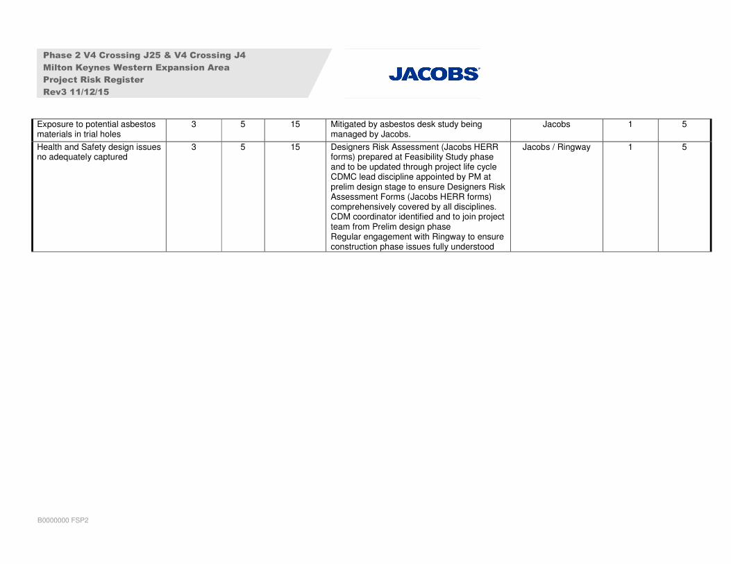
Exposure to potential asbestos materials in trial holes
3 5 15 Mitigated by asbestos desk study being managed by Jacobs.
Jacobs 1 5
Health and Safety design issues no adequately captured
3 5 15 Designers Risk Assessment (Jacobs HERR forms) prepared at Feasibility Study phase and to be updated through project life cycle CDMC lead discipline appointed by PM at prelim design stage to ensure Designers Risk Assessment Forms (Jacobs HERR forms) comprehensively covered by all disciplines. CDM coordinator identified and to join project team from Prelim design phase Regular engagement with Ringway to ensure construction phase issues fully understood
Jacobs / Ringway 1 5


