Abstract—In a metal forming process, the friction between the material and the tools influences the process by modifying the stress distribution of the workpiece. This frictional behaviour is often taken into account by using a constant coefficient of friction in the finite element simulations of sheet metal forming processes. However, friction coefficient varies in time and space with many parameters. The Stribeck friction model is investigated in this study to predict springback behaviour of AA6061-T4 sheets during V-bending process. The coefficient of friction in Stribeck curve depends on sliding velocity and contact pressure. The plane-strain bending process is simulated in ABAQUS/Standard. We compared the computed punch load-stroke curves and springback related to the constant coefficient of friction with the defined friction model. The results clearly showed that the new friction model provides better agreement between experiments and results of numerical simulations. The influence of friction models on stress distribution in the workpiece is also studied numerically. Keywords—Friction model, Stress distribution, V-bending. I. INTRODUCTION HEET metal forming is one of the oldest manufacturing processes known to mankind, and bending can probably be considered its most basic variant [1]. Bending is a process by which metal can be deformed by plastically deforming the material and changing its shape. The material is stressed beyond the yield strength but below the ultimate tensile strength. In a quest to improve fuel economy, the automobile manufacturers have been seriously looking at light metals to lightweight their vehicles. Significant weight saving can be achieved by replacing parts made from mild steel with those made from lightweight materials (aluminum and magnesium alloys) and high specific strength materials (ultra-high- strength and stainless steels). Such materials are less formable than mild steel, and parts made from them lack dimensional control because of the significant amount of springback that they produce after forming [2]. Springback is defined as the elastic recovery of the sheet metal that occurs after a forming operation is completed. It is M. Ramezani is currently pursuing his Ph.D. program in School of Mechanical Engineering, University Sains Malaysia. (corresponding author phone: +604 599 6300; fax: +604 594 1025; e-mail: [email protected]). Z.M. Ripin is an Associate Professor and dean of School of Mechanical and Aerospace Engineering, Universiti Sains Malaysia (e-mail: [email protected]). a common phenomenon in sheet metal forming, caused by the release of stored energy in the material during unloading [3]. Springback is a growing concern as manufacturers increasingly rely on materials with higher strength-to-modulus ratios than the traditional low-strength steel. Today apart from CAD/CAM activities, engineering simulation tools based on the finite element method are employed regularly in the design of sheet metal forming in industries. With the increased use of FE simulations in tooling departments, the forming analyses of sheet metals components are used more frequently in the design feasibility studies of production tooling. These computer tools allow the design engineer to investigate the process and material parameters. The reliability of predicted formability and the accuracy of the estimated deformed geometry for a given part depend on the selected computational modeling approach [4]. Despite the well developed material behaviour models, metal forming simulations often do not yield the correct results. This is generally because of using very simplified friction model. Coulomb friction model is a simple model frequently used in simulations. In this model, the ratio between friction force and normal force, defined as the coefficient of friction c μ , that considered to be constant [5]. However, particularly in lubricated systems, friction depends on a large number of parameters, e.g., the micro-geometry, the macro-geometry, the lubricant and the operational parameters: velocity, temperature and normal load [6]. If one of these parameters change, the coefficient of friction will also changes. This is a known behaviour and generally known as 'Stribeck' behavior [2]. From this it is obvious that a model which describes μ as a function of local contact conditions is needed. The development of friction models for sheet metal forming simulations is complicated by the fact that any of a variety of lubrication regimes may co-exist in the sheet-tooling interface [7]. Wilson [8] described four basic lubrication regimes in metal working: thick film, thin film, mixed and boundary lubrication regimes. Moreover, he showed that the traditional Coulomb friction model is inappropriate for sheet metal forming simulations. Schey [9] explored the effect of drawing speed and lubricant viscosity on coefficient of friction using drawbead simulation tests. The results showed that the coefficient of friction decreases with increasing the viscosity × velocity product. Saha et al. [10] investigated the relationship between friction and process variables including sliding speed, strip strain and strain rate in the boundary lubrication regime using a sheet metal forming simulator which stretches a strip around a cylindrical pin. Friction was found to decrease with Effect of Friction Models on Stress Distribution of Sheet Materials during V-Bending Process Maziar Ramezani, and Zaidi Mohd Ripin S World Academy of Science, Engineering and Technology 56 2009 654
Transcript
Abstract—In a metal forming process, the friction between the
material and the tools influences the process by modifying the stress distribution of the workpiece. This frictional behaviour is often taken into account by using a constant coefficient of friction in the finite element simulations of sheet metal forming processes. However, friction coefficient varies in time and space with many parameters. The Stribeck friction model is investigated in this study to predict springback behaviour of AA6061-T4 sheets during V-bending process. The coefficient of friction in Stribeck curve depends on sliding velocity and contact pressure. The plane-strain bending process is simulated in ABAQUS/Standard. We compared the computed punch load-stroke curves and springback related to the constant coefficient of friction with the defined friction model. The results clearly showed that the new friction model provides better agreement between experiments and results of numerical simulations. The influence of friction models on stress distribution in the workpiece is also studied numerically.
I. INTRODUCTION HEET metal forming is one of the oldest manufacturing processes known to mankind, and bending can probably
be considered its most basic variant [1]. Bending is a process by which metal can be deformed by plastically deforming the material and changing its shape. The material is stressed beyond the yield strength but below the ultimate tensile strength.
In a quest to improve fuel economy, the automobile manufacturers have been seriously looking at light metals to lightweight their vehicles. Significant weight saving can be achieved by replacing parts made from mild steel with those made from lightweight materials (aluminum and magnesium alloys) and high specific strength materials (ultra-high-strength and stainless steels). Such materials are less formable than mild steel, and parts made from them lack dimensional control because of the significant amount of springback that they produce after forming [2].
Springback is defined as the elastic recovery of the sheet metal that occurs after a forming operation is completed. It is
M. Ramezani is currently pursuing his Ph.D. program in School of
Mechanical Engineering, University Sains Malaysia. (corresponding author phone: +604 599 6300; fax: +604 594 1025; e-mail: [email protected]).
Z.M. Ripin is an Associate Professor and dean of School of Mechanical and Aerospace Engineering, Universiti Sains Malaysia (e-mail: [email protected]).
a common phenomenon in sheet metal forming, caused by the release of stored energy in the material during unloading [3]. Springback is a growing concern as manufacturers increasingly rely on materials with higher strength-to-modulus ratios than the traditional low-strength steel.
Today apart from CAD/CAM activities, engineering simulation tools based on the finite element method are employed regularly in the design of sheet metal forming in industries. With the increased use of FE simulations in tooling departments, the forming analyses of sheet metals components are used more frequently in the design feasibility studies of production tooling. These computer tools allow the design engineer to investigate the process and material parameters. The reliability of predicted formability and the accuracy of the estimated deformed geometry for a given part depend on the selected computational modeling approach [4]. Despite the well developed material behaviour models, metal forming simulations often do not yield the correct results. This is generally because of using very simplified friction model. Coulomb friction model is a simple model frequently used in simulations. In this model, the ratio between friction force and normal force, defined as the coefficient of friction cμ , that considered to be constant [5]. However, particularly in lubricated systems, friction depends on a large number of parameters, e.g., the micro-geometry, the macro-geometry, the lubricant and the operational parameters: velocity, temperature and normal load [6]. If one of these parameters change, the coefficient of friction will also changes. This is a known behaviour and generally known as 'Stribeck' behavior [2]. From this it is obvious that a model which describes μ as a function of local contact conditions is needed.
The development of friction models for sheet metal forming simulations is complicated by the fact that any of a variety of lubrication regimes may co-exist in the sheet-tooling interface [7]. Wilson [8] described four basic lubrication regimes in metal working: thick film, thin film, mixed and boundary lubrication regimes. Moreover, he showed that the traditional Coulomb friction model is inappropriate for sheet metal forming simulations. Schey [9] explored the effect of drawing speed and lubricant viscosity on coefficient of friction using drawbead simulation tests. The results showed that the coefficient of friction decreases with increasing the viscosity × velocity product. Saha et al. [10] investigated the relationship between friction and process variables including sliding speed, strip strain and strain rate in the boundary lubrication regime using a sheet metal forming simulator which stretches a strip around a cylindrical pin. Friction was found to decrease with
Effect of Friction Models on Stress Distribution of Sheet Materials during V-Bending Process
Maziar Ramezani, and Zaidi Mohd Ripin
S
World Academy of Science, Engineering and Technology 56 2009
654
increasing sliding velocity for all test conditions. It is shown from the work of Schipper [11] that it is possible to predict the frictional behaviour of lubricated concentrated contacts as a function of the operational conditions. This work is based on the 'Stribeck' behaviour and offers a first possibility to combine the different influences in a theoretical model. Ramezani et al. [2] developed a friction model based on Stribeck friction model which takes into account the local contact conditions. This model was applied to V-bending process of ultra-high-strength steel sheets and the results clearly showed that the new friction model has better agreement with experimental results.
In the present paper, V-bending of aluminum alloy 6061-T4 sheets were investigated experimentally and numerically. The springback behaviour of sheets was studied using numerical simulation with the commercial finite element software ABAQUS/Standard. Two kinds of friction models were used for simulations: Coulomb friction model and Stribeck friction model. The finite element prediction of springback using these two kinds of friction models have been compared with the experimental results. The influence of friction models on stress distribution of sheet metals was investigated numerically. This gives us better insight that how the new friction model produces better results in FE simulations.
II. FRICTION MODELS
A. Coulomb Friction Model The easiest and probably the most well known friction
model is Coulomb friction model. Though it greatly over simplifies the frictional phenomena it is widely used to describe the friction in mechanical contacts. In this model, the ratio between friction force and normal force, defined as the coefficient of friction, is considered to be constant. Coulomb friction model can be formulated as
nFcfF μ= (1)
where cμ is the Coulomb coefficient of friction, fF is the
sliding friction force and nF the normal load in the contact.
B. Stribeck Friction Model Stribeck is credited for carrying out the first systematic
experiments unfolding a clear view of the characteristic curve of the coefficient of friction versus speed. In recognition of his contribution, this curve is called the “Stribeck curve” [12]. The Stribeck curve has also been proven to be useful for identifying boundary, mixed, elasto-hydrodynamic and hydrodynamic lubrication regimes [13]. In sheet metal forming processes, contact regions operate in boundary and mixed lubrication regimes. For this reason a study of the frictional behaviour of sheet metal forming contacts operating in the boundary lubrication regime and the upper part of the mixed lubrication regime is most important.
The theoretical model for kinetic friction based on Stribeck behavior is presented in full details in Ramezani et al. [2,5]. A brief description of the model is presented below. Surface roughness can be modeled as composed set of spherical summits which have the same radius and their heights
following a statistical distribution, as for instance a Gaussian distribution. In lubricated contact surface between die and sheet, the total normal load nF is shared by the
hydrodynamic lifting force hF and the summit interacting
force cF , respectively.
F cF hF n += (2)
Similarly, the total friction force fF is the sum of two
components
∑ ∫∫∫∫=
+=+=N
i Ac
Ah
iCi
h
dAcidAhF cfF hfF f1
..,, ττ
(3) with hfF , the hydrodynamic friction force; cfF , the
summit interacting friction force; N the number of summits;
icA the area of contact of a single summit i ; hA
the contact
area of the hydrodynamic component; icτ the shear stress at
the summit contact i and hτ the shear stress of the hydrodynamic component.
The expression for hydrodynamic friction force hfF , is based on the Bair-Winer model [14] and is represented as
aBLhcu
eF Lhf 2).)(
1.(,τη
τ−
−= (4)
with B the contact length and u the relative velocity. The limiting shear stress τ L varies in accordance to pressure described by:
pmLL βττ 00+= (5)
where 0Lτ is the limiting shear stress at ambient pressure,
0β is the slope of the limiting shear stress-pressure relation,
and mP is the mean pressure of Hertzian contact.
For a single summit, the coefficient of friction icμ is
pci
cici
τμ = (6)
Assuming that icμ is constant for all summits, we arrive at
the following relationship for the friction force:
∑ ∫∫∑ ∫∫==
==N
i A
N
i AC
iCiCi dAcipcicdAcipciF cf
11, μμ
Fccμ= (7)
where cμ can be determined from experiments. Hence, the kinetic coefficient of friction can be obtained from
World Academy of Science, Engineering and Technology 56 2009
655
F n
F ccF hfF n
F fk
μμ
+==
, (8)
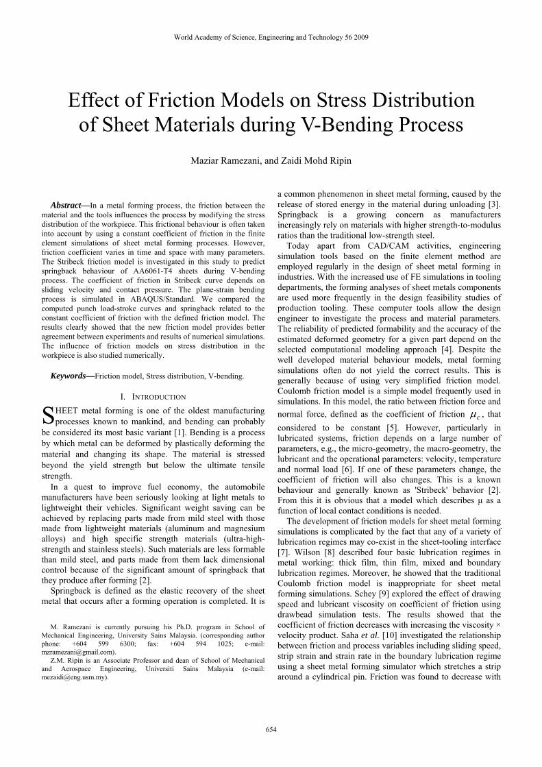
A sample Stribeck curves calculated by varying u for different normal loads are shown in Fig. 1. According to Fig. 1, the coefficient of friction decreases with increasing the sliding velocity and normal load. This is comparable to the observation made by Schey [9] where experimental works on drawbead simulation test showed similar effect of reducing coefficient of friction with increasing velocity and normal load.
Fig. 1 Stribeck curves as a function of sliding velocity and normal
load
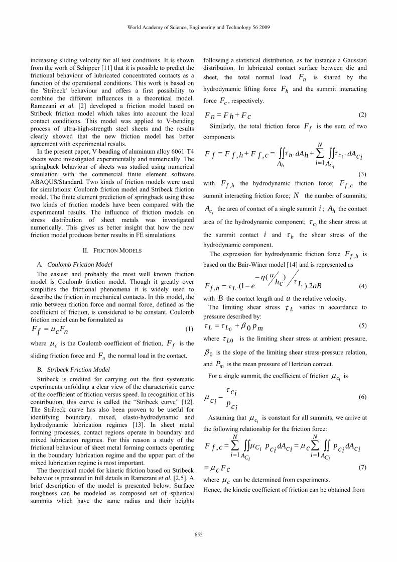
III. V-BENDING EXPERIMENTS AND SIMULATIONS V-bend die and punch were designed and built to install on
a model 3367 Instron universal testing machine as shown in Fig. 2. Punch and die are fixed on the ram of the Instron machine. Sheet materials were bent by the punch and die having an angle of o90 at the forming speed of 100mm/min. After the forming load was released, specimens were removed from the test device and springback results measured approximately 60 seconds after unloading were recorded. The dimensions of the sheet metal specimens used in the V-bending tests were 80mm length and 1mm thickness. The sample was not restrained during the bending process. Before each test, the punch, die and sheet were cleaned and dusted to reduce any sticking between the contact surfaces. The die was then lubricated using an oil-based lubricant in order to minimize friction between the die and sheet.
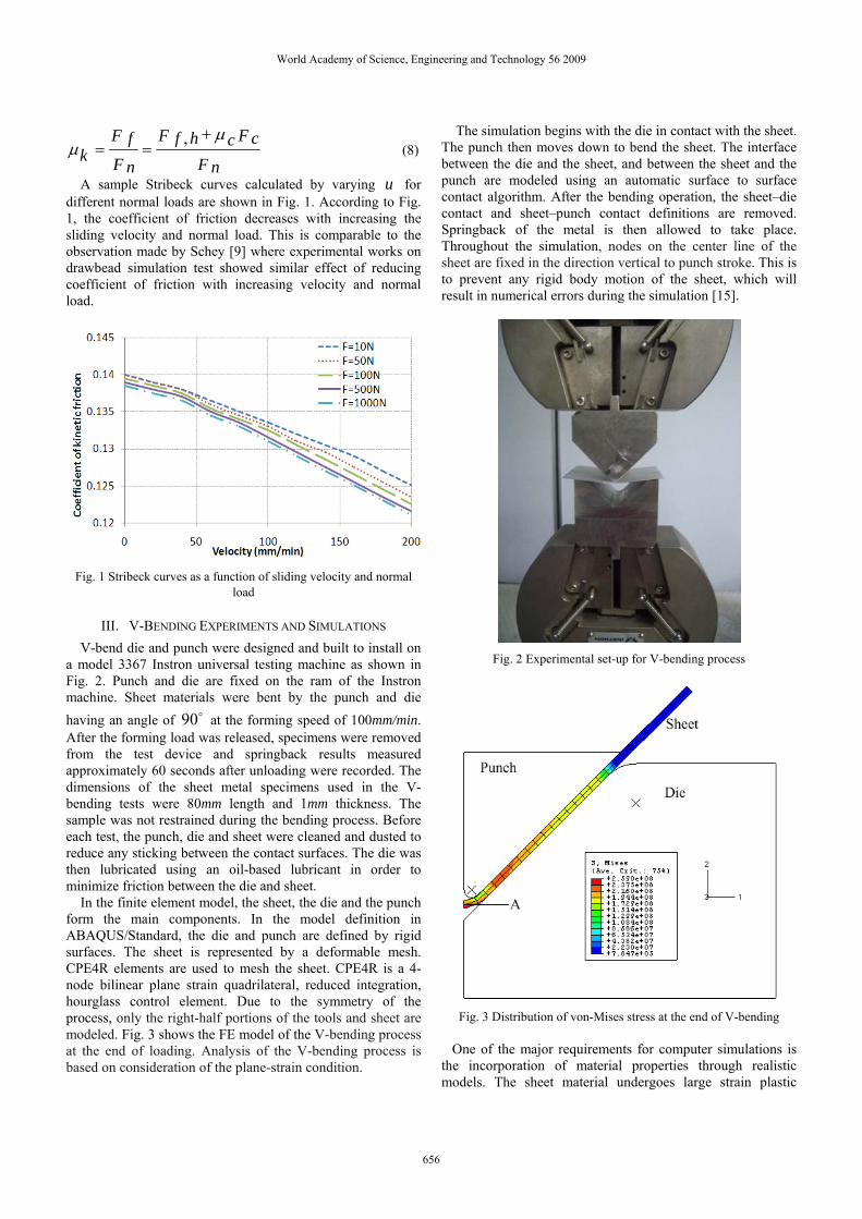
In the finite element model, the sheet, the die and the punch form the main components. In the model definition in ABAQUS/Standard, the die and punch are defined by rigid surfaces. The sheet is represented by a deformable mesh. CPE4R elements are used to mesh the sheet. CPE4R is a 4-node bilinear plane strain quadrilateral, reduced integration, hourglass control element. Due to the symmetry of the process, only the right-half portions of the tools and sheet are modeled. Fig. 3 shows the FE model of the V-bending process at the end of loading. Analysis of the V-bending process is based on consideration of the plane-strain condition.
The simulation begins with the die in contact with the sheet. The punch then moves down to bend the sheet. The interface between the die and the sheet, and between the sheet and the punch are modeled using an automatic surface to surface contact algorithm. After the bending operation, the sheet–die contact and sheet–punch contact definitions are removed. Springback of the metal is then allowed to take place. Throughout the simulation, nodes on the center line of the sheet are fixed in the direction vertical to punch stroke. This is to prevent any rigid body motion of the sheet, which will result in numerical errors during the simulation [15].
Fig. 2 Experimental set-up for V-bending process
Fig. 3 Distribution of von-Mises stress at the end of V-bending
One of the major requirements for computer simulations is the incorporation of material properties through realistic models. The sheet material undergoes large strain plastic
World Academy of Science, Engineering and Technology 56 2009
656
deformation and therefore true stress–true strain test data up to failure are required in order to define the suitable sheet material model in the simulations. The von-Mises yield surface is used to define isotropic yielding. It is defined by giving the value of the uniaxial yield stress as a function of uniaxial equivalent plastic strain. The necessary sheet material mechanical properties for simulations were obtained from tensile tests. Flat I-shape specimens from 1mm thick AA6061-T4 along their rolling directions were prepared and tested in laboratory according to ASTM E 8M standard and the results were used in the simulations.
The punch–sheet and sheet–die contacts in V-bending process are simulated using two friction models. First, using a Coulomb friction model, i.e., constant coefficient of sliding friction with 14.0=μc . The value of coefficient of friction is based on historical data for similar cases [2]. Second, the coefficient of sliding friction is taken as a function of contact pressure and sliding velocity as predicted by Stribeck friction model (see, Fig. 1). The Stribeck curves are implemented to the model through contact property option of ABAQUS software. This option is used to introduce friction properties into the mechanical surface interaction models. Slip-rate-dependent and contact-pressure-dependent options are used to import the Stribeck curves into ABAQUS/Standard.
IV. RESULTS AND DISCUSSION
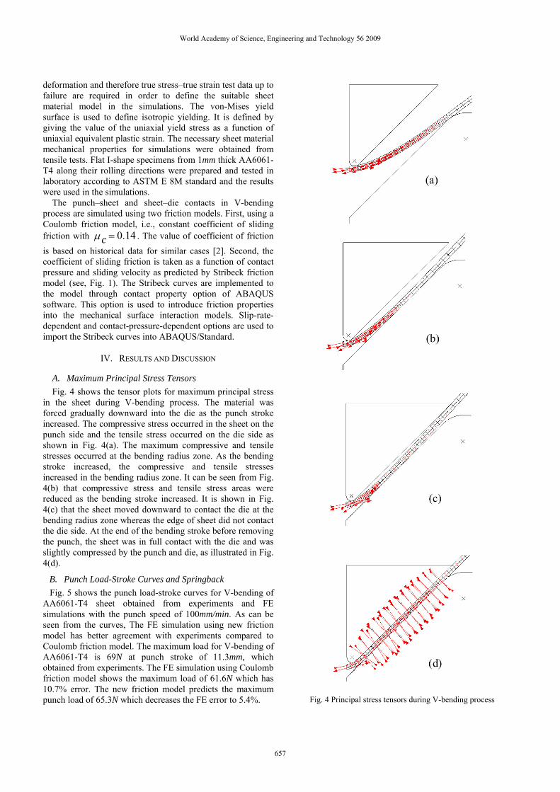
A. Maximum Principal Stress Tensors Fig. 4 shows the tensor plots for maximum principal stress
in the sheet during V-bending process. The material was forced gradually downward into the die as the punch stroke increased. The compressive stress occurred in the sheet on the punch side and the tensile stress occurred on the die side as shown in Fig. 4(a). The maximum compressive and tensile stresses occurred at the bending radius zone. As the bending stroke increased, the compressive and tensile stresses increased in the bending radius zone. It can be seen from Fig. 4(b) that compressive stress and tensile stress areas were reduced as the bending stroke increased. It is shown in Fig. 4(c) that the sheet moved downward to contact the die at the bending radius zone whereas the edge of sheet did not contact the die side. At the end of the bending stroke before removing the punch, the sheet was in full contact with the die and was slightly compressed by the punch and die, as illustrated in Fig. 4(d).
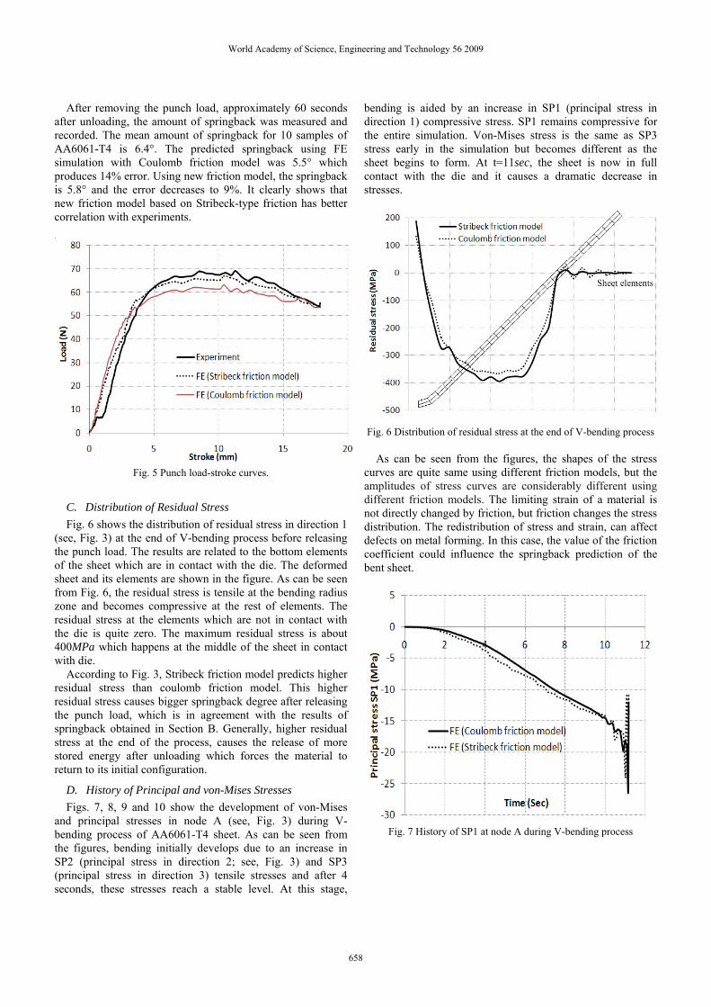
B. Punch Load-Stroke Curves and Springback Fig. 5 shows the punch load-stroke curves for V-bending of AA6061-T4 sheet obtained from experiments and FE simulations with the punch speed of 100mm/min. As can be seen from the curves, The FE simulation using new friction model has better agreement with experiments compared to Coulomb friction model. The maximum load for V-bending of AA6061-T4 is 69N at punch stroke of 11.3mm, which obtained from experiments. The FE simulation using Coulomb friction model shows the maximum load of 61.6N which has 10.7% error. The new friction model predicts the maximum punch load of 65.3N which decreases the FE error to 5.4%.
Fig. 4 Principal stress tensors during V-bending process
World Academy of Science, Engineering and Technology 56 2009
657
After removing the punch load, approximately 60 seconds after unloading, the amount of springback was measured and recorded. The mean amount of springback for 10 samples of AA6061-T4 is 6.4°. The predicted springback using FE simulation with Coulomb friction model was 5.5° which produces 14% error. Using new friction model, the springback is 5.8° and the error decreases to 9%. It clearly shows that new friction model based on Stribeck-type friction has better correlation with experiments.
Fig. 5 Punch load-stroke curves.
C. Distribution of Residual Stress Fig. 6 shows the distribution of residual stress in direction 1
(see, Fig. 3) at the end of V-bending process before releasing the punch load. The results are related to the bottom elements of the sheet which are in contact with the die. The deformed sheet and its elements are shown in the figure. As can be seen from Fig. 6, the residual stress is tensile at the bending radius zone and becomes compressive at the rest of elements. The residual stress at the elements which are not in contact with the die is quite zero. The maximum residual stress is about 400MPa which happens at the middle of the sheet in contact with die.
According to Fig. 3, Stribeck friction model predicts higher residual stress than coulomb friction model. This higher residual stress causes bigger springback degree after releasing the punch load, which is in agreement with the results of springback obtained in Section B. Generally, higher residual stress at the end of the process, causes the release of more stored energy after unloading which forces the material to return to its initial configuration.
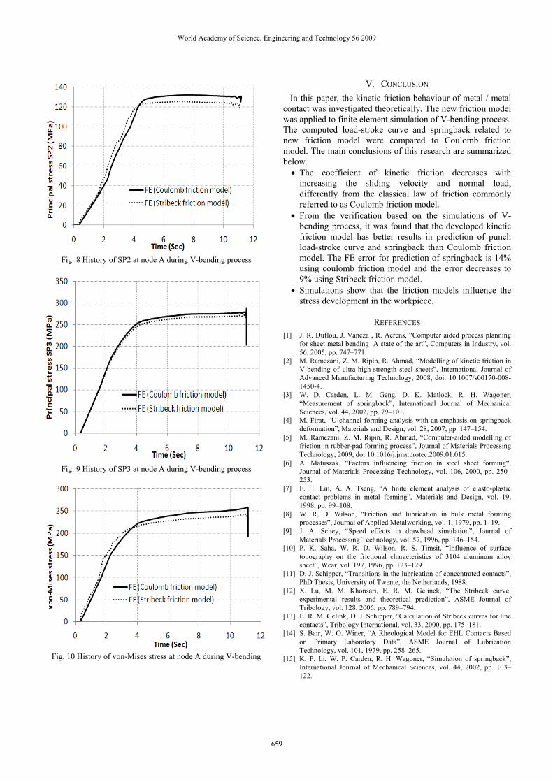
D. History of Principal and von-Mises Stresses Figs. 7, 8, 9 and 10 show the development of von-Mises
and principal stresses in node A (see, Fig. 3) during V-bending process of AA6061-T4 sheet. As can be seen from the figures, bending initially develops due to an increase in SP2 (principal stress in direction 2; see, Fig. 3) and SP3 (principal stress in direction 3) tensile stresses and after 4 seconds, these stresses reach a stable level. At this stage,
bending is aided by an increase in SP1 (principal stress in direction 1) compressive stress. SP1 remains compressive for the entire simulation. Von-Mises stress is the same as SP3 stress early in the simulation but becomes different as the sheet begins to form. At t=11sec, the sheet is now in full contact with the die and it causes a dramatic decrease in stresses.
Fig. 6 Distribution of residual stress at the end of V-bending process
As can be seen from the figures, the shapes of the stress curves are quite same using different friction models, but the amplitudes of stress curves are considerably different using different friction models. The limiting strain of a material is not directly changed by friction, but friction changes the stress distribution. The redistribution of stress and strain, can affect defects on metal forming. In this case, the value of the friction coefficient could influence the springback prediction of the bent sheet.
Fig. 7 History of SP1 at node A during V-bending process
World Academy of Science, Engineering and Technology 56 2009
658
Fig. 8 History of SP2 at node A during V-bending process
Fig. 9 History of SP3 at node A during V-bending process
Fig. 10 History of von-Mises stress at node A during V-bending
V. CONCLUSION In this paper, the kinetic friction behaviour of metal / metal contact was investigated theoretically. The new friction model was applied to finite element simulation of V-bending process. The computed load-stroke curve and springback related to new friction model were compared to Coulomb friction model. The main conclusions of this research are summarized below.
• The coefficient of kinetic friction decreases with increasing the sliding velocity and normal load, differently from the classical law of friction commonly referred to as Coulomb friction model.
• From the verification based on the simulations of V-bending process, it was found that the developed kinetic friction model has better results in prediction of punch load-stroke curve and springback than Coulomb friction model. The FE error for prediction of springback is 14% using coulomb friction model and the error decreases to 9% using Stribeck friction model.
• Simulations show that the friction models influence the stress development in the workpiece.
REFERENCES [1] J. R. Duflou, J. Vancza , R. Aerens, “Computer aided process planning
for sheet metal bending A state of the art”, Computers in Industry, vol. 56, 2005, pp. 747–771.
[2] M. Ramezani, Z. M. Ripin, R. Ahmad, “Modelling of kinetic friction in V-bending of ultra-high-strength steel sheets”, International Journal of Advanced Manufacturing Technology, 2008, doi: 10.1007/s00170-008-1450-4.
[3] W. D. Carden, L. M. Geng, D. K. Matlock, R. H. Wagoner, “Measurement of springback”, International Journal of Mechanical Sciences, vol. 44, 2002, pp. 79–101.
[4] M. Firat, “U-channel forming analysis with an emphasis on springback deformation”, Materials and Design, vol. 28, 2007, pp. 147–154.
[5] M. Ramezani, Z. M. Ripin, R. Ahmad, “Computer-aided modelling of friction in rubber-pad forming process”, Journal of Materials Processing Technology, 2009, doi:10.1016/j.jmatprotec.2009.01.015.
[6] A. Matuszak, “Factors influencing friction in steel sheet forming“, Journal of Materials Processing Technology, vol. 106, 2000, pp. 250–253.
[7] F. H. Lin, A. A. Tseng, “A finite element analysis of elasto-plastic contact problems in metal forming”, Materials and Design, vol. 19, 1998, pp. 99–108.
[8] W. R, D. Wilson, “Friction and lubrication in bulk metal forming processes”, Journal of Applied Metalworking, vol. 1, 1979, pp. 1–19.
[9] J. A. Schey, “Speed effects in drawbead simulation”, Journal of Materials Processing Technology, vol. 57, 1996, pp. 146–154.
[10] P. K. Saha, W. R. D. Wilson, R. S. Timsit, “Influence of surface topography on the frictional characteristics of 3104 aluminum alloy sheet”, Wear, vol. 197, 1996, pp. 123–129.
[11] D. J. Schipper, “Transitions in the lubrication of concentrated contacts”, PhD Thesis, University of Twente, the Netherlands, 1988.
[12] X. Lu, M. M. Khonsari, E. R. M. Gelinck, “The Stribeck curve: experimental results and theoretical prediction”, ASME Journal of Tribology, vol. 128, 2006, pp. 789–794.
[13] E. R. M. Gelink, D. J. Schipper, “Calculation of Stribeck curves for line contacts”, Tribology International, vol. 33, 2000, pp. 175–181.
[14] S. Bair, W. O. Winer, “A Rheological Model for EHL Contacts Based on Primary Laboratory Data”, ASME Journal of Lubrication Technology, vol. 101, 1979, pp. 258–265.
[15] K. P. Li, W. P. Carden, R. H. Wagoner, “Simulation of springback”, International Journal of Mechanical Sciences, vol. 44, 2002, pp. 103–122.
World Academy of Science, Engineering and Technology 56 2009