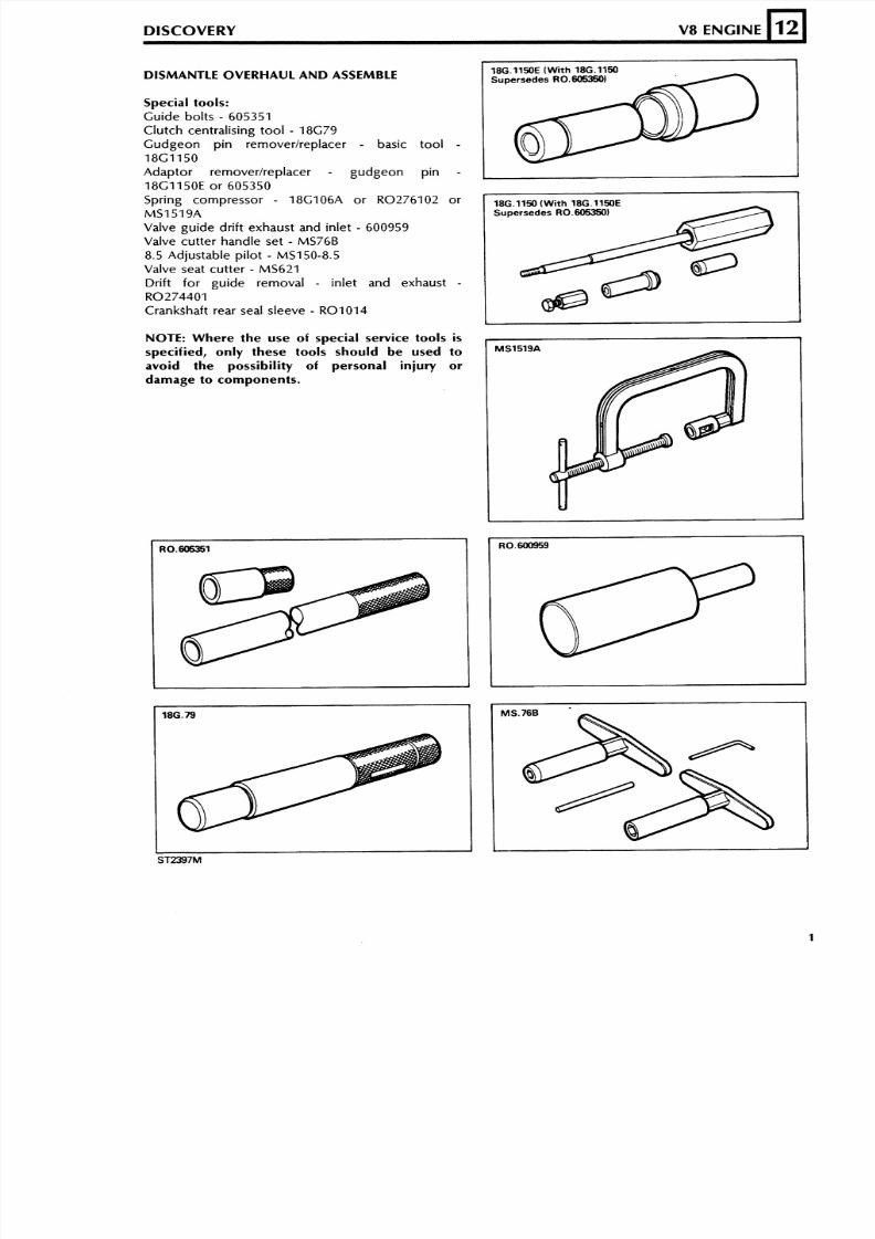
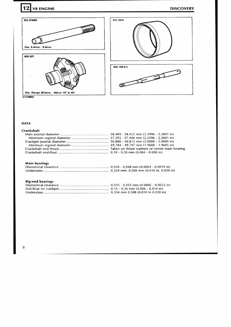
DISMANTLE OVERHAUL AND ASSEM BL E DISCOVERY V8 ENGINE Special tools: Guide bolts - 605351 Clutch centralising tool - 18G79 Gudgeon pin removerlreplacer - basic tool - 18G1150 Adaptor removerlreplacer - gudgeon pin - 18G1150E or 605350 Spring compressor - 18G106A or R0276102 or MS1519A Valve guide drift exhaust and inlet - 600959 Valve cutter handle set - MS76B 8.5 Adjustable pilot - MS150-8.5 Valve seat cutter - MS621 Drift for guide removal - inlet and exhaust - R0274401 CrankShaft rear seal sleeve - R01014 12 NOTE: Where the use of special service tools is specified, only these tools should be used to avoid the possibility of personal injury or damage t o components. 18G.1150E (With 18G.1150 Supersedes R0.605350) - 18G.1150 (With 18G.1150E Supersedes R0.605350) I
Fi t -in connect ing ro d .................................................. Press fit
Clearance in piston ..................................................... 0,002 - 0,007 m m (0.0001 - 0.0003 in)
DISCOVERY V8 ENGINE
PistonsClearance in b ore measured at bo t to m of sk ir t
a t r ight angles to gu dgeo n p i n ................................... 0,018 - 0,040 m m (0.0007 - 0.001 6 in)
12
Piston ringsNum ber o f compress ion ............................................. 2
N u m b e r o f o i l ............................................................. 1No . 1 compression r ing ............................................... Ch rom e parallel faced
No.2 compression r ing .............................................. Stepped to 'L' shape and marked 'T' o r 'TOP'
W id t h o f compress ion ................................................ 1,56 - 1 /59 m m (0.061 5 - 0.0625 in)
Compress ion r ing gap................................................
0,44-
0,57 m m 0.017-
0.022 in)Oil r ing type ................................................................ Perfect circle, type 98-6
Oil r ing w id th .............................................................. 4.81 1 m m (0.1894 in) max
CamshaftLocat ion ...................................................................... Central
Nu mb er of bear ings ....................................................5Dr ive ...........................................................................hain 9,52 m m (0.375 in) pitch x 54 pitches
Valves
Length:In le t .........................................................................16,59 - 117,35 m m (4.590 - 4,620 in)
Exhaust ................................................................. 116,59 - 117,35 m m (4.590 - 4.620 in)
Seat angle:
In le t .........................................................................5' - 45,5"
In le t .........................................................................9,75 - 40,OO m m (1.565 - 1,575 in)
Exhaust .................................................................... 4,226 - 34,480 m m (1.3475 - 1.3575 in)
Stem diameter:
In le t ......................................................................... ,664 - 8,679 m m (0.341 1 - 0.341 7 in)
Exhaust ....................................................................,651 - 8,666 m m (0.3406 - 0.3412 in)
Stem t o gu ide c learance:In le t ......................................................................... ,025 - 0,066 m m (0.001 0 - 0.001 0 - 0.0026 in)
Exhaust .................................................................... ,038 - 0,078 m m (0.0015 - 0.0031 in)Valve lift ( inlet and exhaust) ........................................ 9,93 m m (0.390 in)
Valve spr ing length f i t ted ........................................... 40,4 m m (1.590 in) at pressure of 29,5 k g (65 Ibs)
Free length ..............................................................1,2 m m (3.200 in)
..............omp resse d length at 4,2 kg (9.3 Ib) load 45.7 m m (1.800 in)
8/6/2019 V8 Overhaul
http://slidepdf.com/reader/full/v8-overhaul 4/45
TORQUE WRENCH SElllNGS
12
Air intake adaptor to carbs .......................................Alternator mounting bracket to cylinder head ..........Alternator to mounting bracket ................................Alternator to adjusting link .......................................Chainwheel to camshaft ...........................................Connecting rod bolt .................................................Clutch attachment to flywheel .................................Cylinder head:................................................................uter row
Centre row ...............................................................inner row .................................................................................................................istributor clamp nut
Exhaust manifold to cylinder head ....................................................................................an attachment
Flywheel to crankshaft ..............................................Inlet manifold to cylinder heads ...............................Lifting eye to cylinder heads ....................................Main bearing cap bolts .............................................Main bearing cap rear bolts ......................................Manifold gasket clamp bolt ......................................Oil pump cover to timing cover ...............................Oil plug ....................................................................Oil relief valve cap ....................................................Oil sump drain plug .................................................Oil sump to cylinder block .......................................Oil sump to cylinder block . ear .............................Rocker cover to cylinder head ..................................Rocker shaft bracket to cylinder head ......................Spark plug ................................................................Starter motor attachment .........................................Damper to crankshaft ...............................................Timing cover to cylinder block .................................Tempatrol unit to water pump .................................Water pump pulley to water pump hub ...................Water pump and timing cover to cylinder block ......
V8 ENGINE DISCOVERY
Ib f f t
8/6/2019 V8 Overhaul
http://slidepdf.com/reader/full/v8-overhaul 5/45
DISMANTLE
DISCOVERY V8 ENGINE
Remove the engine from the vehicle and clean the
exterior. In the interests of safety and efficient
working secure the engine to a recognised engine
stand. Drain and discard the sump oil. Observe the
precautions concerning used engine oil in the
'introduction' section 01 .
12
WARNING: Where the use of an engine stand i s
necessary, it i s absolutely essential to follow the
stand manufacturer's instructions to ensure safe
and effective use of the equipment.
L
REMOVE ANCILLARY EQUIPMENT
Before commencing, and whilst dismantling, make a
careful note of the position of brackets, clips,
harnesses, pipes, hoses, filters and other
miscellaneous and any non-standard items tofacilitate reassembly.
1. Remove the following items of equipment:
Starter motor.
Alternator and mounting bracket.
Power steering pump.
Disconnect spark plug H.T. leads and remove
the disributor cap.
Clutch
Fan blades, pulley and drive belt.
Dipstick and engine mounting brackets.
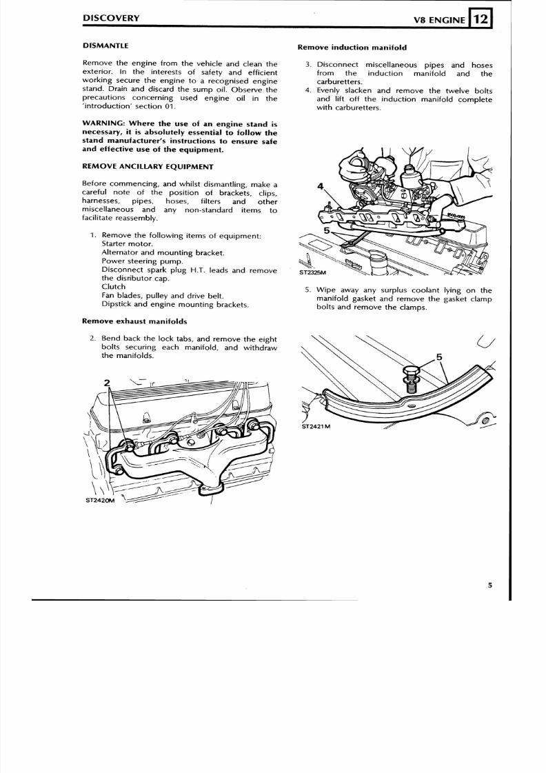
Remove exhaust manifolds
2. Bend back the lock tabs, and remove the eight
bolts securing each manifold, and withdraw
the manifolds.
Remove induction manifold
3. Disconnect miscellaneous pipes and hoses
from the induction manifold and the
carburetters.
4. Evenly slacken and remove the twelve bolts
and lift off the induction manifold complete
with carburetters.
5. Wipe away any surplus coolant lying on the
manifold gasket and remove the gasket clamp
bolts and remove the clamps.
8/6/2019 V8 Overhaul
http://slidepdf.com/reader/full/v8-overhaul 6/45
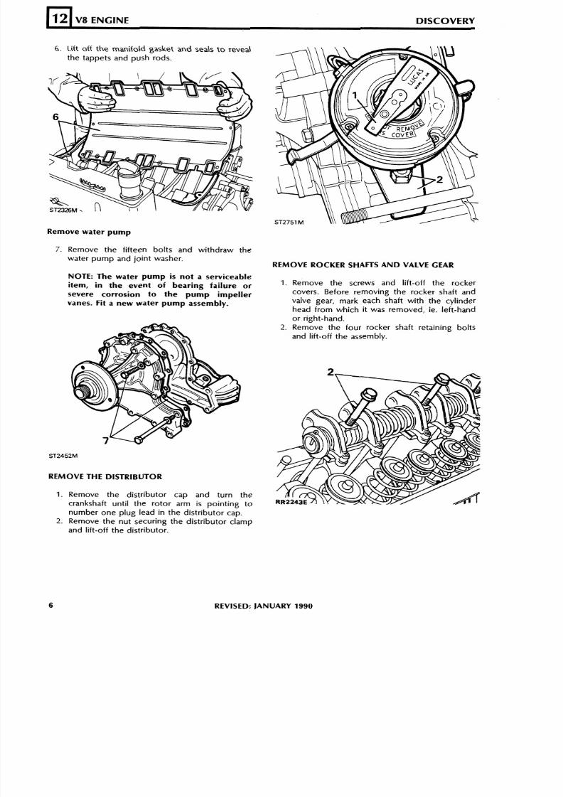
6. Lift off the manifold gasket and seals to reveal
the tappets and push rods.
12
Remove water pump
V8 ENGINE DISCOVERY
7. Remove the fifteen bolts and withdraw the
water pump and joint washer.
NOTE: The water pump is not a serviceable
item, in the event of bearing failure or
severe corrosion to the pump impeller
vanes. Fit a new water pump assembly.
REMOVE THE DISTRIBUTOR
1. Remove the distributor cap and turn the
crankshaft until the rotor arm is pointing to
number one plug lead in the distributor cap.
2. Remove the nut securing the distributor clamp
and lift-off the distributor.
REMOVE ROCKER SHAnS AND VALVE GEAR
1. Remove the screws and lift-off the rocker
covers. Before removing the rocker shaft and
valve gear, mark each shaft with the cylinder
head from which it was removed, ie. left-hand
or right-hand.
2. Remove the four rocker shaft retaining boltsand lift-off the assembly.
REVISED: JANUARY1990
8/6/2019 V8 Overhaul
http://slidepdf.com/reader/full/v8-overhaul 7/45
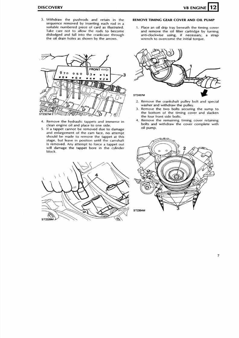
3. Withdraw the pushrods and retain in the REMOVE TI M IN G GEAR COVER AND OIL P U M P
sequence removed by inserting each rod in a
suitable numbered piece of card as illustrated. 1. Place an oil drip tray beneath the timing coverTake care not to a l low the rods to become and remove the oil filter cartridge by turningdislo dge d and fall into th e crankcas e thro ugh anti-clockwise using, i f necessary, a strap
th e oil drain holes as shown by the arrows. wrench to overcome the initial torque.
DISCOVERY V8 ENGINE
2. Remove the crankshaft pulley bolt and specialwasher and withdraw the pulley.
3 . Remove the two bol ts securing the sump to
the bottom of the timing cover and slackenthe four f ront s ide bol ts.
L
12
4. Remove the hydraulic tappets and immerse in 4. Remove the remaining timing cover retaining
clean engine oil and place to one side. bolts and withdraw the cover complete with
5. I f a t appe t canno t be removed d u e to damage oil pump.
and enlargement of the cam face , no a t t empt
shou ld be made to remove the t appe t a t th i sstage, but leave in position until the camshaftis removed. Any at tempt to fo rce a tapp et ou twill damage the tappet bore in the cylinderblock.
ST2354M
L
8/6/2019 V8 Overhaul
http://slidepdf.com/reader/full/v8-overhaul 8/45
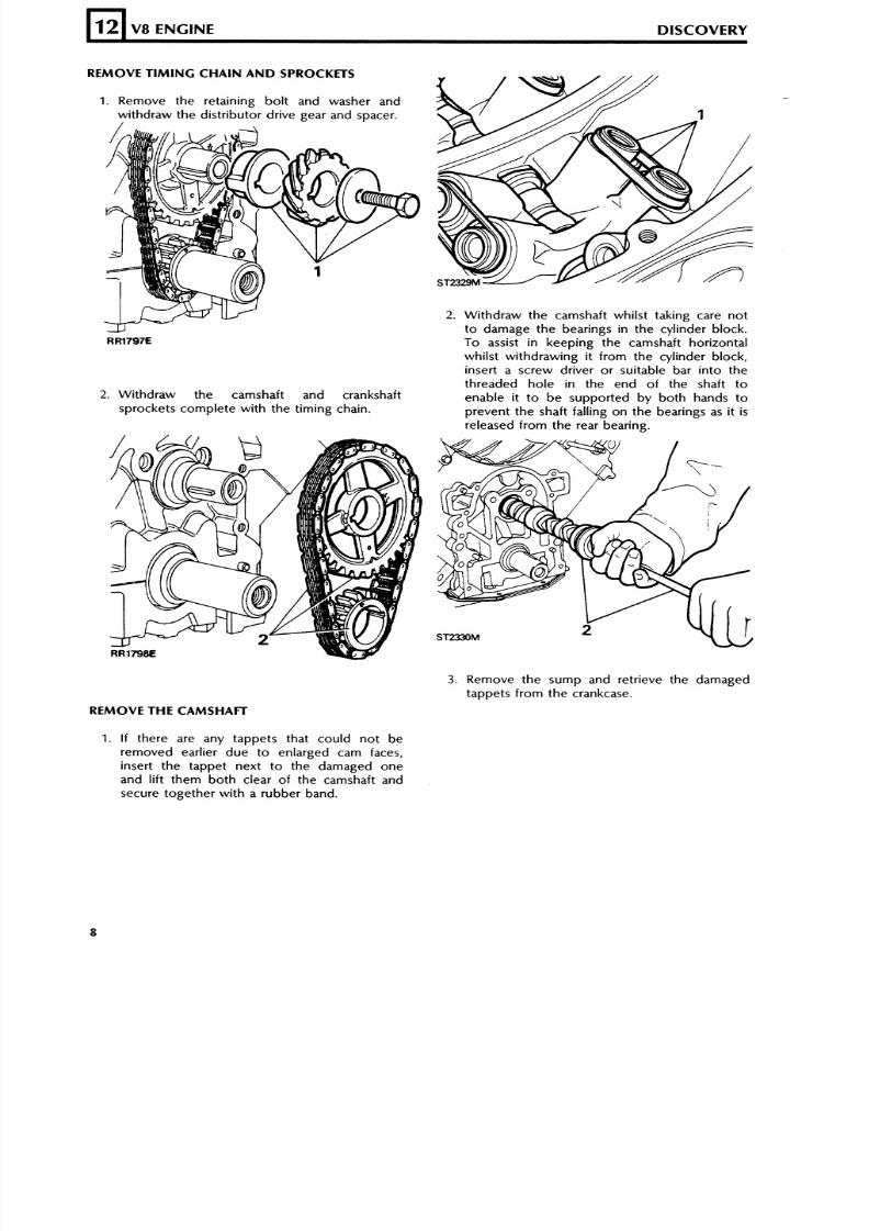
REMOVE TI MI NG CHAIN A ND SPROCKETS
1. Remove the retaining bolt and washer andwithdraw the distributor drive gea r and spacer.
2. Withdraw the camshaft whilst taking care notto damage the bearings in the cylinder block.
Rm797E To assist in keeping the camshaft horizontal
whilst withdrawing it from the cylinder block,insert a screw driver or suitable bar into the
threaded hole in the end of the shaft to2. Withdraw the camshaft and crankshaft enab le it t o b e sup porte d by both hands t o
sprockets complete with the timing chain. prevent the shaft falling on the bearings as it isreleased from the rear bearing.
12
3 . Remove the sump and retr ieve the damagedtappets from the crankcase.
V8 ENGINE DISCOVERY
REMOVE THE CAMS HAFl
1. If there are any tappets that could not beremoved earlier due to enlarged cam faces,inser t the tappe t nex t to the damaged o neand lift the m b oth clear o f the camshaft andsecure together with a rubber band.
8/6/2019 V8 Overhaul
http://slidepdf.com/reader/full/v8-overhaul 9/45
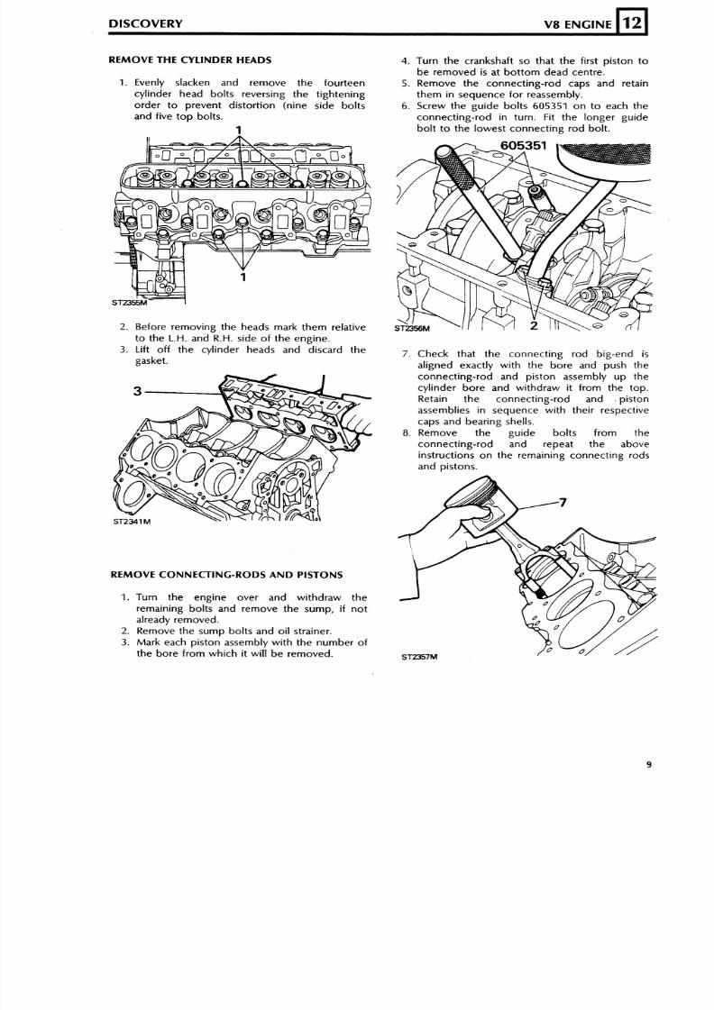
REMOVE THE CYLINDER HEADS
DISCOVERY V8 ENGINE
1. Evenly slacken and remove the fourteen
cylinder head bolts reversing the tightening
order to prevent distortion (nine side bolts
and five top bolts.
1
12
2. Before removing the heads mark them relative
to the L.H. and R.H. side of the engine.
3. Lift off the cylinder heads and discard the
gasket.
L
REMOVE CONNECTING-RODS AND PISTONS
1. Turn the engine over and withdraw the
remaining bolts and remove the sump, i f not
already removed.
2. Remove the sump bolts and oil strainer.
3. Mark each piston assembly with the number of
the bore from which it will be removed.
4. Turn the crankshaft so that the first piston to
be removed is at bottom dead centre.
5. Remove the connecting-rod caps and retain
them in sequence for reassembly.
6. Screw the guide bolts 605351 on to each the
connecting-rod in turn. Fit the longer guide
bolt to the lowest connecting rod bolt.
7. Check that the connecting rod big-end i s
aligned exactly with the bore and push the
connecting-rod and piston assembly up the
cylinder bore and withdraw it from the top.
Retain the connecting-rod and . piston
assemblies in sequence with their respectivecaps and bearing shells.
8. Remove the guide bolts from the
connecting-rod and repeat the above
instructions on the remaining connecting rods
and pistons.
8/6/2019 V8 Overhaul
http://slidepdf.com/reader/full/v8-overhaul 10/45
8/6/2019 V8 Overhaul
http://slidepdf.com/reader/full/v8-overhaul 11/45
EXAMINE AND OVERHAUL CYLINDER BLOCK
DISCOVERY V8 ENGINE
1. Degrease the cylinder block and carry out a
thorough visual examination checking for
cracks and damage.
2. The cylin der bo res are cast iro n lined and are
shrunk into the bores. The l iners must not be
bored o ut more than 0 ,508 m m and if theyhave been bored already beyond this oversize
the cy l inder b lock must be renewed.
3. Assuming that, so far, the cylinder block is
sat is factory for recondi t ioning, proceed to the
next stage of the examination. To check the
main bearing caps and saddles for distort ion,
f i t the main bear ing caps without bear ing
shel ls and t ighten to the correct torque.
S lacken and remove the bo l t on one s ide o f
each bearing cap and check with a feeler
gauge that n o clearance exists at the join t face
between the cap and saddle. A clearanceindicates ei ther a bent bol t , d is tor t ion of the
caps, or b lock or that the cap has been f i led
or mach ined in an a t tempt to reduce the
clearance du e to wear in the bearings. Main
bearing caps are not available separately from
the cylinder block and if a clearance exists the
b lock mus t be renewed.
L
12
Camshaft bearings
I
4. Each of the five cam shaft bearings is a
different diameter, with the smallest at the rear
and the largest at the front. If the bearings are
excessively worn, pit ted, or scored the
cy l inder b loc k must b e renewed s ince the
bearings are not available as replacement
parts.
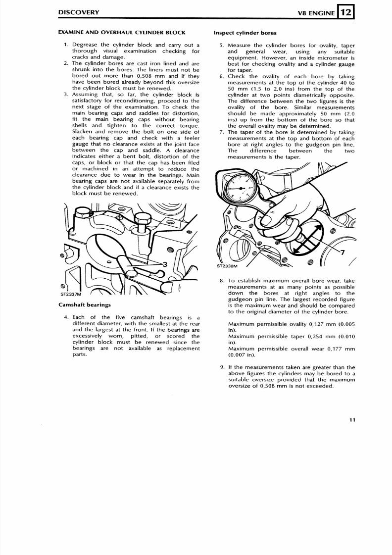
inspect cylinder bores
5. Measure the cylinder bores for ovality, taper
and general wear, using any suitable
equipment. However, an inside micrometer is
best for checking ovality and a cylinder gauge
for taper.
6. Check the oval i ty of each bore by tak ingmeasurements at the t op of th e cy l inder 40 to
50 m m (1 .5 to 2 .0 ins ) f rom the to p o f the
cylinder at two points diametr ically opposite.
The di f ference b etw ee n the t w o f igures is the
ovality of the bore. Similar measurements
should be made approx imately 50 mm (2.0ins ) up f r om the bo t t om o f t he bo r e so t hat
the overall ovality may be determined.
7. The taper of the b or e is dete rmine d by taking
measurements a t the to p and bo t to m of each
bore at r ight angles to the gudgeon pin l ine,
The dif ference be twee n the tw omeasurements is the taper.
8. To establish ma xim um overall bor e wear, take
measurements at as many points as possibledown the bores at r ight angles to the
gudgeon pin l ine. The largest recorded f igure
i s the maximum wear and should be comparedto the or ig inal d iameter of the cylinder bore.
Max imum permissib le ovali ty 0,127 mm (0.005
in).
Ma xim um permissible taper 0,254 m m (0.010in).
Ma xim um permissible overall wear 0,177 m m
(0.007 in).
9. If the measurements taken are greater than the
above f igures the cylinders may be bored to a
suitable oversize provided that the maximumovers ize of 0,508 m m is not exceeded.
8/6/2019 V8 Overhaul
http://slidepdf.com/reader/full/v8-overhaul 12/45
10. When the cylinders are being rebored it is
essential to fit the bearing caps and tighten
the bolts to the correct torque to prevent
distortion during the machining operation.
12
NOTE: Pistons are available in service
standard size and in oversizes of 0,25 m m
(0.010 i n) and 0,50 m m (0.020 in). Service
standard size pistons are supplied 0,0254
mrn (0.001 i n) oversize. When f itt ing new
service standard size pistons to a cylinder
block, check for correct piston to bore
clearance, hon ing the bore if necessary.
Bottom of piston skirt-bore clearance
sh ou ld b e 0,018 to 0,040 m m (0.0007 t o
0.0016 in).
V8 ENGINE DISCOVERY
NOTE: The temperature of the piston and
cylinder bloc k must b e the same to ensure
accurate measurement.
I )
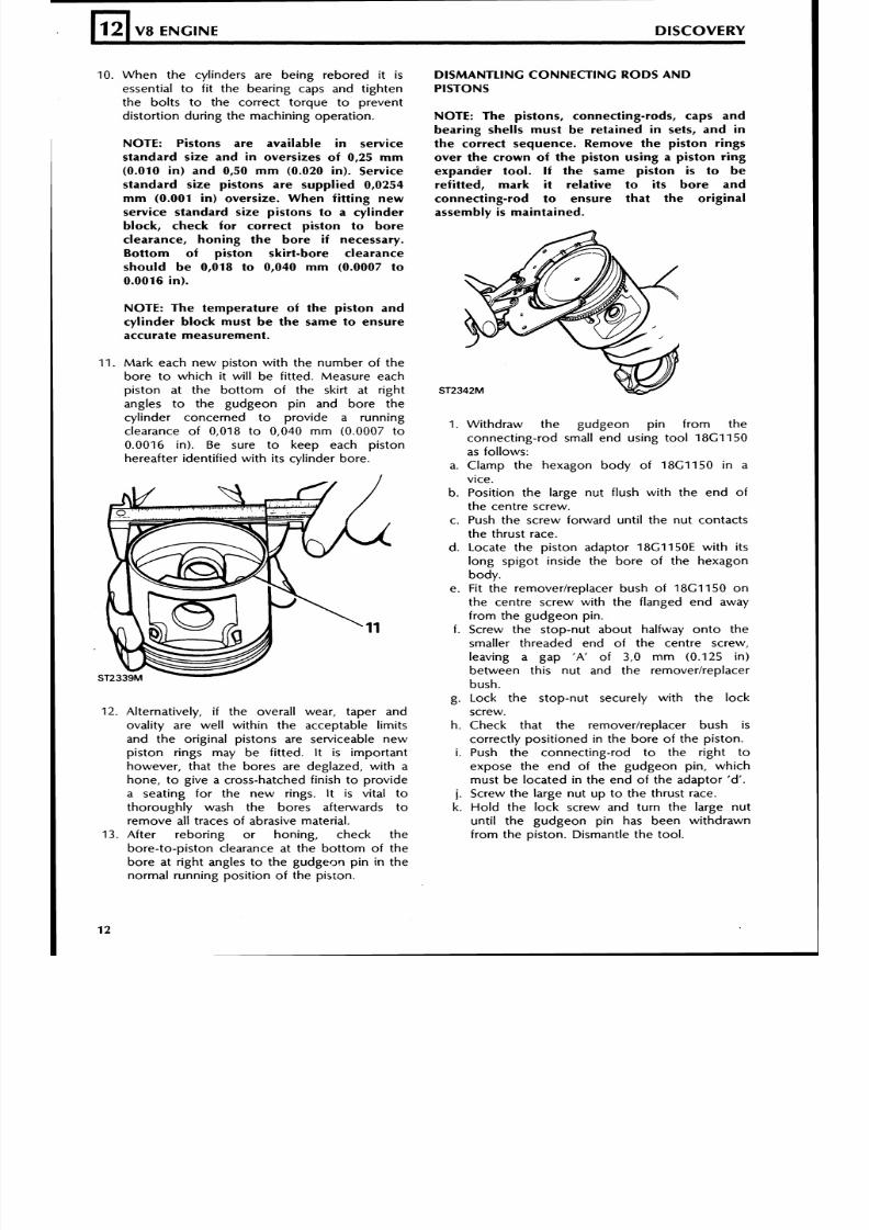
11. Mark each new piston with the number of the
bore to which it will be fitted. Measure each
piston at the bottom of the skirt at right
angles to the gudgeon pin and bore the
cylinder concerned to provide a running
clearance of 0,018 to 0,040 mm (0.0007 o
0.0016 in). Be sure to keep each piston
hereafter identified with its cylinder bore.
Alternatively, i f the overall wear, taper and
ovality are well within the acceptable limits
and the original pistons are serviceable new
piston rings may be fitted. It is important
however, that the bores are deglazed, with a
hone, to give a cross-hatched finish to provide
a seating for the new rings. It is vital to
thoroughly wash the bores afterwards to
remove all traces of abrasive material.
After reboring or honing, check the
bore-to-piston clearance at the bottom of thebore at right angles to the gudgeo~ in in the
normal running position of the piston.
DISMANTLING CONNECTING RODS AND
PISTONS
NOTE: The pistons, connecting-rods, caps and
bearing shells must be retained in sets, and in
the correct sequence. Remove the piston rings
over the crown of the piston using a piston ring
expander tool. I f the same piston is to b e
refitted, mark i t relative to i ts bore and
connecting-rod to ensure that the original
assembly is maintained.
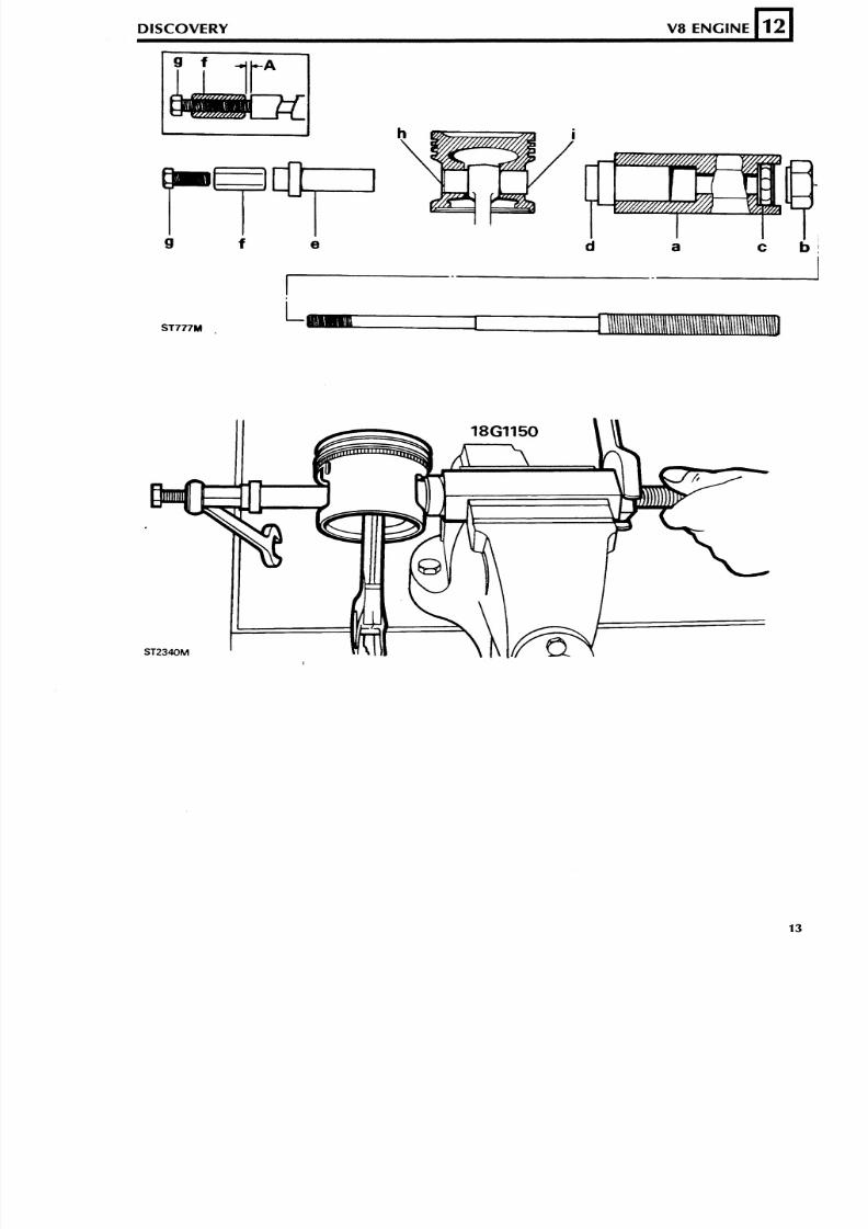
1. Withdraw the gudgeon pin from the
connecting-rod small end using tool 18C1150
as follows:
a. Clamp the hexagon body of 18G1150 in a
vice.
b. Position the large nut flush with the end of
the centre screw.c. Push the screw forward until the nut contacts
the thrust race.
d. Locate the piston adaptor 18G1150E with its
long spigot inside the bore of the hexagon
body.
e. Fit the removerlreplacer bush of 18Cl150 on
the centre screw with the flanged end away
from the gudgeon pin.
f. Screw the stop-nut about halfway onto the
smaller threaded end of the centre screw,
leaving a gap 'A' of 3,O mm (0.125 in)
between this nut and the remover/replacer
bush.
g. Lock the stop-nut securely with the lock
screw.
h. Check that the removerlreplacer bush is
correctly positioned in the bore of the piston.
i. Push the connecting-rod to the right to
expose the end of the gudgeon pin, which
must be located in the end of the adaptor 'd'.
j. Screw the large nut up to the thrust race.
k. Hold the lock screw and turn the large nut
until the gudgeon pin has been withdrawn
from the piston. Dismantle the tool.
8/6/2019 V8 Overhaul
http://slidepdf.com/reader/full/v8-overhaul 13/45
DISCOVERY V8 ENGINE
L
12
8/6/2019 V8 Overhaul
http://slidepdf.com/reader/full/v8-overhaul 14/45
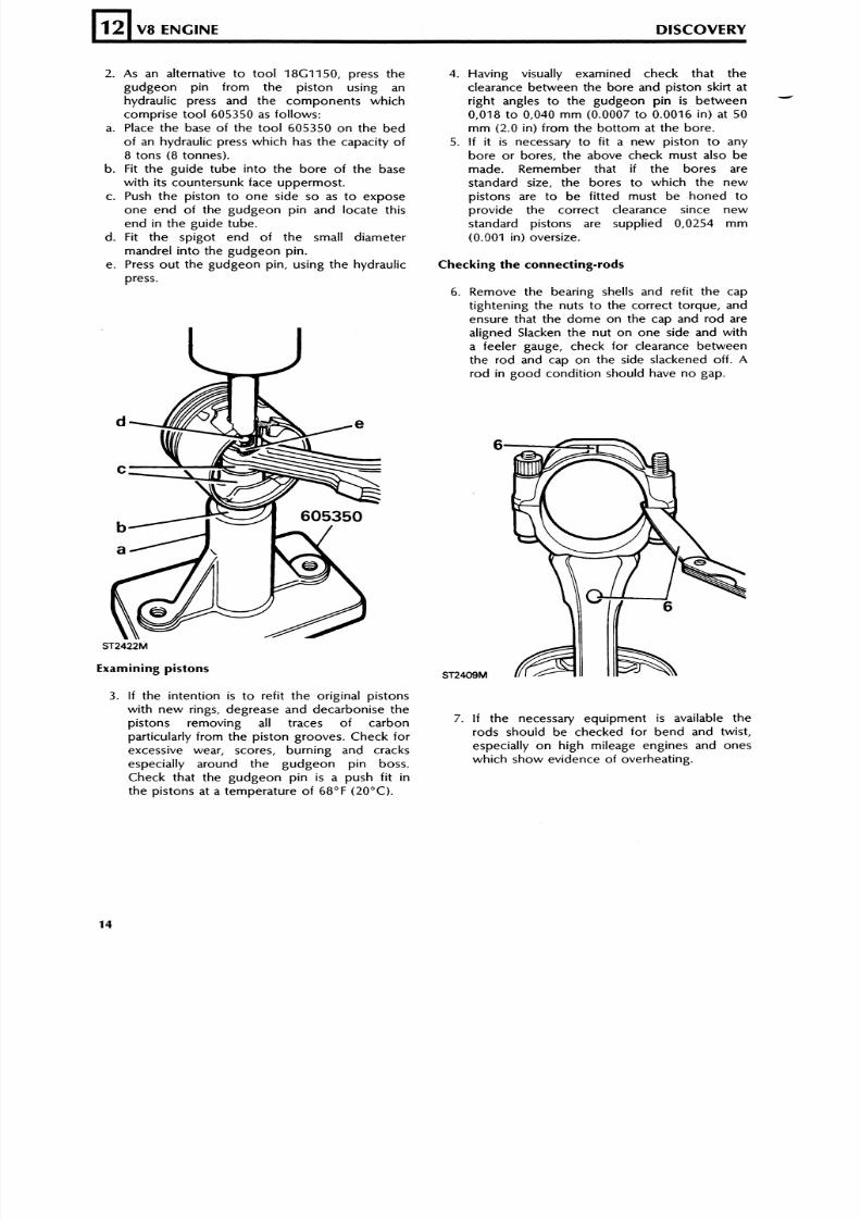
2. As an alternative to tool 18G1150, press the
gudgeon pin from the piston using an
hydraulic press and the components which
comprise tool 605350 as follows:
a. Place the base of the tool 605350 on the bed
of an hydraulic press which has the capacity of
8 tons (8 tonnes).
b. Fit the guide tube into the bore of the basewith its countersunk face uppermost.
c. Push the piston to one side so as to expose
one end of the gudgeon pin and locate this
end in the guide tube.
d. Fit the spigot end of the small diameter
mandrel into the gudgeon pin.
e. Press out the gudgeon pin, using the hydraulic
press.
12
Examining pistons
V8 ENGINE DISCOVER Y
3. If the intention is to refit the original pistons
with new rings, degrease and decarbonise the
pistons removing all traces of carbon
particularly from the piston grooves. Check for
excessive wear, scores, burning and cracks
especially around the gudgeon pin boss.
Check that the gudgeon pin is a push fit in
the pistons at a temperature of 68°F (20°C).
4. Having visually examined check that the
clearance between the bore and piston skirt at
right angles to the gudgeon pin is between-
0,018 to 0,040 mm (0.0007 to 0.0016 in) at 50
mm (2.0 in) from the bottom at the bore.
5. If it is necessary to fit a new piston to any
bore or bores, the above check must also be
made. Remember that if the bores are
standard size, the bores to which the new
pistons are to be fitted must be honed to
provide the correct clearance since new
standard pistons are supplied 0,0254 mm
(0.001 in) oversize.
Checking the connecting-rods
6. Remove the bearing shells and refit the cap
tightening the nuts to the correct torque, and
ensure that the dome on the cap and rod are
aligned Slacken the nut on one side and witha feeler gauge, check for clearance between
the rod and cap on the side slackened off. A
rod in good condition should have no gap.
7. I f the necessary equipment i s available the
rods should be checked for bend and twist,
especially on high mileage engines and ones
which show evidence of overheating.
8/6/2019 V8 Overhaul
http://slidepdf.com/reader/full/v8-overhaul 15/45
Fitting pis ton s to connecting-rods
DISCOVERY V8 ENGINE
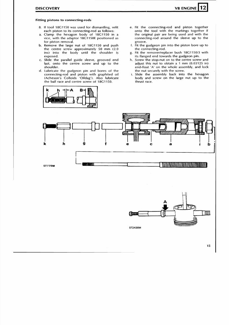
8. If tool 18G1150 was used for dismantling, refit
each piston to its connecting-rod as follows:
a. Clamp the hexagon body of 18G1150 in a
vice, with the adaptor 18G1150E positioned as
for piston removal.
b. Remove the large nut of 18G1150 and push
the centre screw approximately 50 mm (2.0
ins) into the body until the shoulder is
exposed.
c. Slide the parallel guide sleeve, grooved end
last, onto the centre screw and up to the
shoulder.
d. Lubricate the gudgeon pin and bores of the
connecting-rod and piston with graphited oil
(Acheson's Colloids 'Oildag'). Also lubricate
the ball race and centre screw of 18G1150.
12
e. Fit the connecting-rod and piston together
onto the tool with the markings together if
the original pair are being used and with the
connecting-rod around the sleeve up to the
groove.
f. Fit the gudgeon pin into the piston bore up to
the connecting-rod.
g. Fit the remover/replacer bush 18G1150/3 with
its flanged end towards the gudgeon pin.
h. Screw the stop-nut on to the centre screw and
adjust this nut to obtain a Imm (0.03125 in)
end-float 'A' on the whole assembly, and lock
the nut securely with the screw.
i. Slide the assembly back into the hexagon
body and screw on the large nut up to the
thrust race.
8/6/2019 V8 Overhaul
http://slidepdf.com/reader/full/v8-overhaul 16/45
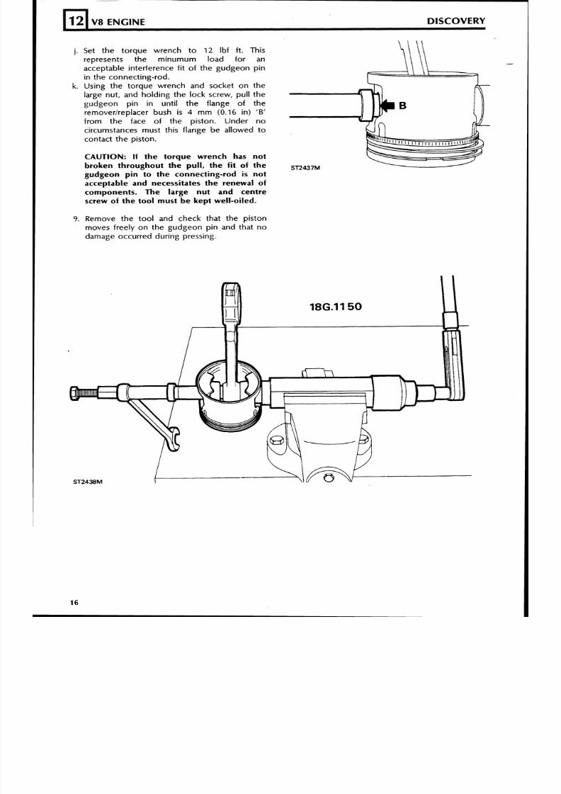
j. Set the torque wrench to 12 Ibf ft. Thisrepresents the minumum load for anacceptable interference fi t of t he gudgeon p inin the connect ing-rod.
k. Using the torque wrench and socket on thelarge nut, and holding the lock screw, pull thegu dg eo n pin in until th e flange of th eremoverlreplacer bush is 4 m m (0 .16 in ) 'B'
f rom the face of the pis ton. Under nocircumstances must this f lange be al lowed to
contact the pis ton.
CAUTION: If the torque wrench has not
broken throughout the pull, the fit of the ST2437M
gudgeon pin to the connecting-rod i s not
acceptable and necessitates the renewal of
components. The large nut and centre
screw of the tool must be kept well-oiled.
12
9. Remove the tool and check that the pis tonmoves f r ee ly on the gudgeon p in and tha t no
damage occurred dur ing press ing.
V8 ENGINE DISCOVERY
8/6/2019 V8 Overhaul
http://slidepdf.com/reader/full/v8-overhaul 17/45
DISCOVERY
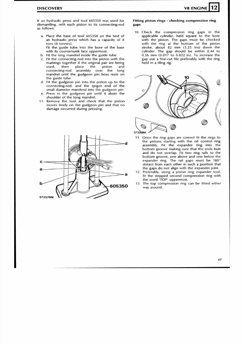
If an hydraulic press and tool 605350 was used for
dismantling, refit each piston to its connecting-rod
as follows:
a. Place the base of too l 605350 on the bed of
an hydraulic press which has a capacity of 8
tons (8 tonnes).
Fit the guide tube into the bore of the basewith its countersunk face uppermost.
b. Fit the long mandrel inside the guide tube.
c. Fit the connecting-rod into the piston with the
markings together i f the original pair are being
used, then place the piston and
connecting-rod assembly over the long
mandrel until the gudgeon pin boss rests on
the guide tube.
d. Fit the gudgeon pin into the piston up to the
connecting-rod, and the spigot end of the
small diameter manderal into the gudgeon pin.
e. Press in the gudgeon pin until it abuts theshoulder of the long mandrel.
11. Remove the tool and check that the piston
moves freely on the gudgeon pin and that no
damage occurred during pressing.
Fitting piston rings - checking com pression ring
gaps
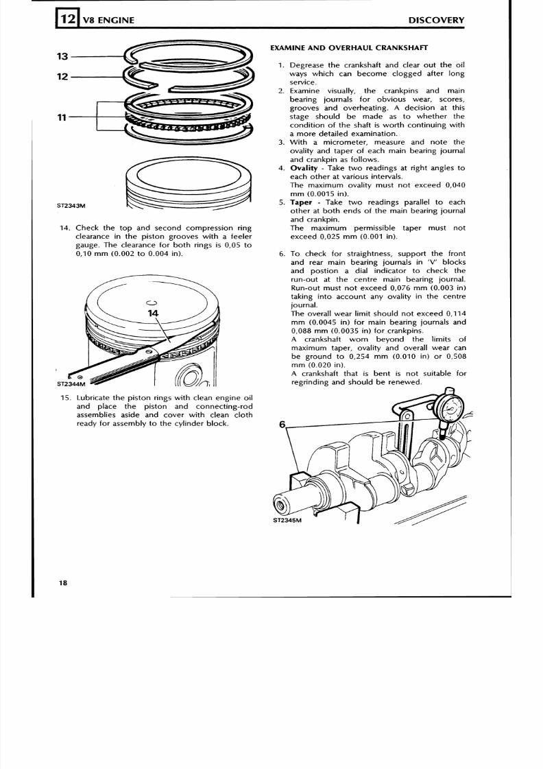
10. Check the compression ring gaps in the
applicable cylinder, held square to the bore
with the piston. The gaps must be checked
with the ring at the bottom of the piston
stroke, about 82 mm (3.25 ins) down thecylinder. The gap should be within 0,44 to
0,56 mm (0.017 to 0.022 in). To increase the
gap use a fine-cut file preferably with the ring
held in a filing rig.
11. Once the ring gaps are correct fit the rings to
the pistons starting with the oil control ringassembly. Fit the expander ring into the
bottom groove making sure that the ends butt
and do not overlap. Fit two ring rails to the
bottom groove, one above and one below the
expander ring. The rail gaps must be 180"
distant from each other in such a position that
the gaps do not align with the expander joint.
12. Preferably, using a piston ring expander tool,
fit the stepped second compression ring with
the word 'TOP' uppermost.
13. The top compression ring can be fitted either
way around.
8/6/2019 V8 Overhaul
http://slidepdf.com/reader/full/v8-overhaul 18/45
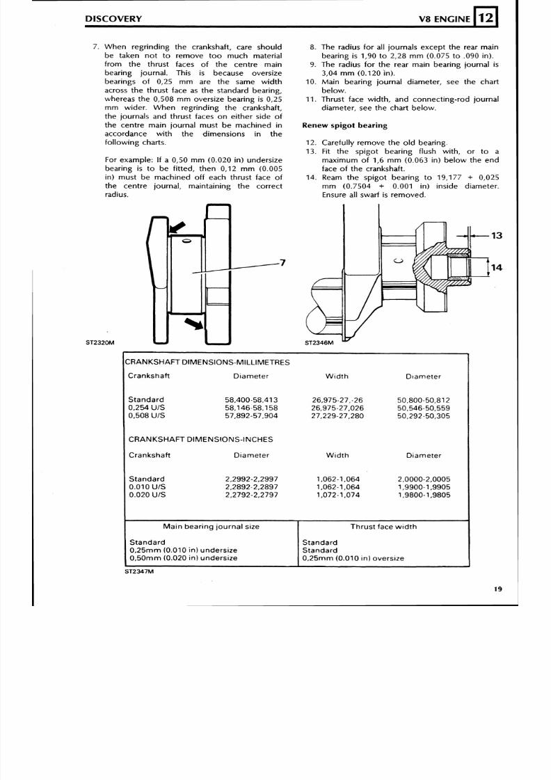
14. Check the top and second compression ring
clearance in the piston grooves with a feeler
gauge. The clearance for both rings i s 0,05 to
0,10 mm (0.002 to 0.004 in).
12
15. Lubricate the piston rings with clean engine oil
and place the piston and connecting-rod
assemblies aside and cover with clean cloth
ready for assembly to the cylinder block.
V8 ENGINE DISCOVERY
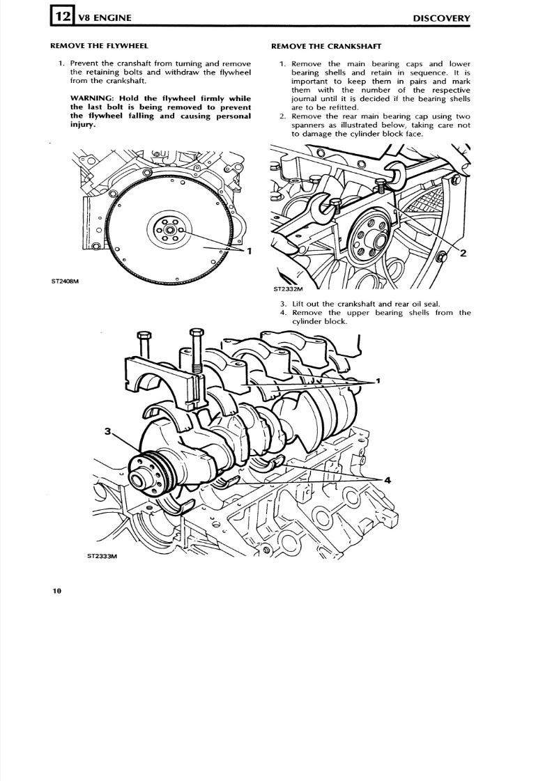
EXAMINE AN D OVERHAUL CRANKSHAFT
1. Degrease the crankshaft and clear out the oil
ways which can become clogged after long
service.
2. Examine visually, the crankpins and main
bearing journals for obvious wear, scores,
grooves and overheating. A decision at this
stage should be made as to whether the
condition of the shaft is worth continuing with
a more detailed examination.
3. With a micrometer, measure and note the
ovality and taper of each main bearing journal
and crankpin as follows.
4 . Oval i ty - Take two readings at right angles to
each other at various intervals.
The maximum ovality must not exceed 0,040
mm (0.0015 in).
5. Taper - Take two readings parallel to each
other at both ends of the main bearing journaland crankpin.
The maximum permissible taper must not
exceed 0,025 mm (0.001 in).
6. To check for straightness, support the front
and rear main bearing journals in 'V ' blocks
and postion a dial indicator to check the
run-out at the centre main bearing journal.
Run-out must not exceed 0,076 mm (0.003 in)
taking into account any ovality in the centre
journal.
The overall wear limit should not exceed 0,114
mm (0.0045 in) for main bearing journals and
0,088 mm (0.0035 in) for crankpins.
A crankshaft worn beyond the limits of
maximum taper, ovality and overall wear can
be ground to 0,254 mm (0.010 in) or 0,508
mm (0.020 in).
A crankshaft that is bent is not suitable for
regrinding and should be renewed.
8/6/2019 V8 Overhaul
http://slidepdf.com/reader/full/v8-overhaul 19/45
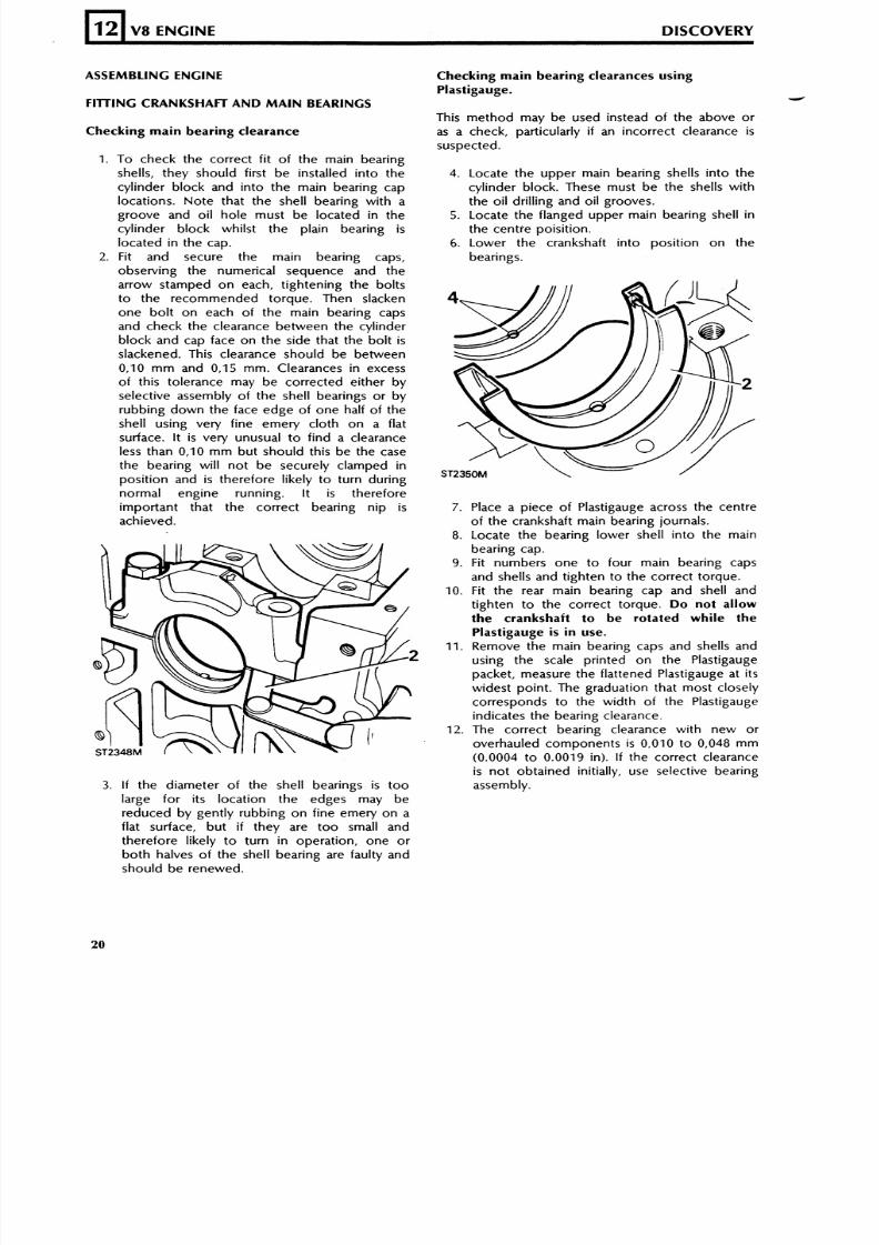
When regr inding the crankshaft , care should
b e t a ke n n o t t o r e m o ve t o o m u ch m a t e r i a l
from the thrust faces of the centre main
bearing journal. This is because oversize
bear ings of 0,25 m m are the same wi dt h
across the thrust face as the standard bearing,
whereas th e 0,508 m m oversize bea ring is 0,25
m m wider . Wh en regr ind ing the crankshaft ,the journals and thrust faces o n either side of
the centre main journal mus t be machined in
accordance wi th the d imensions in the
fol lowing charts.
DISCOVERY V8 ENGINE
For example: If a 0,50 m m (0.020 in) undersize
bear ing is t o be f i t ted, th en 0,12 m m (0.005
in) must be machined of f each thrust face of
the centre journal, maintaining the correct
radius.
128. Th e radius fo r all journals ex cept th e rear ma in
bear ing is 1,90 to 2,28 m m (0.075 t o .090 in) .
9. The radius for the rear main bearing journal is
3,04 m m (0.120 'in).
10. Main bear ing journal diameter, see the chart
be low.11. Thrust face width, and connect ing-rod journal
diameter, see the chart below.
Renew spigot bearing
12. Carefully remove the ol d bear ing.
13. Fit the sp igot bear ing f lush with, o r t o a
maximum o f 1 ,6 m m (0.063 in) be low the end
face of the crankshaft.
14. Ream the spigot bear ing to 19,177 + 0,025
m m (0.7504 + 0.001 in) inside diameter.
Ensure all swarf is remo ved .
CRANKSHAFT DIMENSIONS-MILLIMETRES
Cranksha f t D iamete r
S t a n d a r d 58,400.58,413
0,254 /S 58,146-58.158
0,508U IS 57,892-57,904
I CRANKSHAFT D IMENSIONS- INCHES
Cranksha f t D iamete r
S t a n d a r d 2,2992-2.2997
0.010U IS 2,2892-2,2897
0.020U IS 2,2792-2,2797
W i d t h
W i d t h Diameter
I Ma in bear ing jou rna l s ize I Th r u s t fa ce w id t h ISt a n d a r d0, 25 mm 0.010n) unders ize0, 50 mm 0.020 n) unders ize
StandardStandard0, 25 mm 0.010n) overs ize
8/6/2019 V8 Overhaul
http://slidepdf.com/reader/full/v8-overhaul 20/45
ASSEMBLING ENGINE
12
FITTING CRANKSHAFT AND MAIN BEARINGS
V8 ENGINE DISCOVERY
Checking main bearing clearance
1. To check the correct f i t of the main bear ing
shells, they sho uld f irst b e installed in to thecy l inder b lock and in to the main bear ing cap
locat ions. Note that the shel l bear ing with a
groove and o i l ho le mus t be located in the
cy l inder b lock whi ls t the pla in bear ing is
located i n the cap.
2. Fit and secure th e ma in b earing caps,
observ ing the numer ical sequence and the
arrow stamped o n each, t ightening the bol ts
t o the recom mend ed torque . Then slacken
one bo l t on each o f the main bear ing caps
and check the c learance between the cy l inder
bloc k and cap face o n the s ide that the b ol t isslackened. This clearance should be between
0,10 m m and 0,15 mm . Clearances in excess
of th is to lerance may b e corrected ei ther b y
selective assembly of the shell bearings or by
rubb ing do wn the face edg e o f one ha lf o f the
shel l us ing very f ine emery c loth on a f lat
surface. It is very unu sual t o fin d a clearance
less than 0,10 m m bu t should th is be the case
the bear ing wi l l n o t be securely c lamped in
pos i t ion and is therefore l ikely to turn dur ing
normal engine running. I t is therefore
impor tant that the correct bear ing nip isachieved.
3. I f the diameter of the shell bearings is too
large for i ts locat ion the edges may be
reduced by gent ly rubb ing o n f ine emery on a
flat surface, but i f they are too small and
there fore l ike ly to tu rn i n operat ion , one o r
both halves of the shell bearing are faulty andshou ld b e renewed.
Checking main bearing clearances using
Plastigauge.
This m eth od may b e used instead o f the above o r
as a check, particularly if an incorrect clearance is
suspected.
4. Locate the u ppe r main bearing shells int o thecylinder block. These must be the shells with
the oi l dr i l l ing and o i l grooves.
5. Locate the f langed upp er main bearing shell in
the centre pois i t ion.
6. Lower the crankshaf t into pos i t ion on the
bearings.
7.Place a piece of Plastigauge across the centreof the crankshaft main bearing journals.
8. Locate the be aring lower shell into the main
bearing cap.
9. Fit numbers one to four main bear ing caps
and shel ls and t ighten to the correct torque.
10. Fit the rear main bearing cap and shell and
t igh ten to the cor rec t to rque. Do not allow
the crankshaft to be rotated while the
Plastigauge i s in use.
11. Remove the main bearing caps and shells and
using the scale pr inted on the Plastigauge
packet, measure the flattened Plastigauge at its
widest point. The graduation that most closely
corresponds to the width of the Plastigauge
indicates the bearing clearance.
12. The correct bearing clearance with ne w o r
overhauled components is 0,010 to 0,048 mm
(0.0004 t o 0.0019 in). If the co rrect clearance
is not obtained initially, use selective bearing
assembly.
8/6/2019 V8 Overhaul
http://slidepdf.com/reader/full/v8-overhaul 21/45
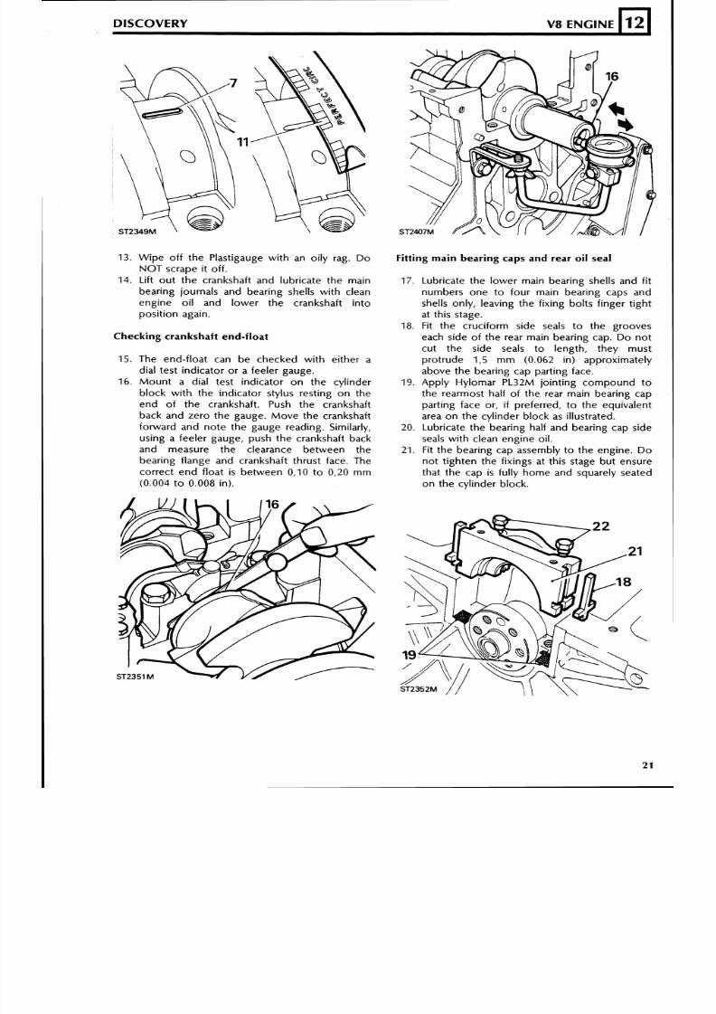
13. W ipe o ff the Plast igauge wi th an oi ly rag. D o
NO T scrape i t o f f .
14. Lif t out the crankshaft and lubr icate the mainbear ing journals and bear ing shells with clean
engine o i l and lower the crankshaf t in to
pos it ion again.
DISCOVERY V8 ENGINE
Fitting main bearing caps and rear oil seal
12
17. Lubr icate the low er m ain bear ing shells and f i tnumbers one to four main bear ing caps and
shells only, leaving the fixing bolts finger tight
at this stage.
18. Fit the cru ciform side seals t o the grooves
each side of the rear main bear ing cap. D o no t
cut the side seals to length, they mustpro trud e 1,5 m m (0.062 in) approximately
above the bear ing cap part ing face.
19. Apply Hylomar PL32M jo in t ing compound to
the rearmost half of the rear main bear ing cap
part ing face or, i f preferred, t o the equivalent
area on the cylinder block as illustrated.20. Lubricate the bearin g half and bearing cap side
seals with clean engine oil.
21. Fit the bea ring cap assembly t o the engine. D o
not t ighten the f ixings at this stage but ensure
that the cap is fully home and squarely seated
o n the cyl inder b lock.
L
Checking crankshaft end-float
15. The end- f loat can be checked wi th e i ther a
dial test in dicator o r a feeler gauge.
16. M ou nt a d ial test ind icator o n the cyl inder
b lock w i th the ind icator stylus rest ing o n the
end of the crankshaft . Push the crankshaft
back and zero the gauge. Move the crankshaftfonvard and note the gauge reading. Similar ly,
using a feeler gauge, push th e crankshaft back
and measure the clearance between the
bearing flange and crankshaft thrust face. The
cor rect en d f loat is betwee n 0,10 t o 0,20 m m
(0.004 to 0.008 in).
8/6/2019 V8 Overhaul
http://slidepdf.com/reader/full/v8-overhaul 22/45
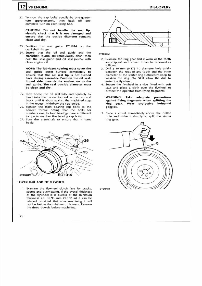
22. Te nsion th e cap bo lts equally by one-quarter
turn approximate ly, then back of f one
comple te tu rn o n each f i x ing bo l t .
12
CAUTION: Do not handle the seal lip,
visually check that it is not damaged and
ensure that the ouside diameter remains
clean and dry.
V8 ENGINE DISCOVERY
23. Posi t ion the seal gu ide R010 14 o n the
crankshaft f lange.
24. Ensure tha t t he oi l seal guide and th e
crankshaft journal are scrupulously clean, then
coat the seal guide and oi l seal journal with
clean engine oi l .
NOTE: The lubricant coating must cover the
seal guide outer surface completely to
ensure that the oil seal lip i s not turned
back during assembly. Position the oil seal,lipped side towards the engine, on to the
seal guide. The seal outside diameter must
be clean and dry.
25. Push ho m e the oi l seal ful ly and squarely by
hand in to the recess formed in the cap and
block unt i l i t abuts against the machined step
in the recess. Withdraw the seal guide.
26. T ighten the main bear ing cap bol ts to the
cor rect torque no t in g that the bol ts for
numbers on e t o four bearings have a d if ferent
torq ue t o num ber f ive bear ing cap bol ts .
27. Turn the crankshaft t o ensure that i t turns
freely.
OVERHAUL AND FIT FLYWHEEL
2. Examine the r ing gear and i f w or n or th e teeth
are ch ipped and broken i t can be renewed as
fol l lows.
3. Dri ll a 10 rnrn (0.375 in) diamete r h ole axially
be tween the roo t o f any too th and the inner
diameter of the starter r ing suff icient ly deep to
weaken the r ing. D o NOT al low the dr i l l toenter the f lywheel.
4. Secure the f lywheel in a vice f i t te d with soft
jaws and p lace a c lo th over the f lywheel to
protec t the op erator f rom f ly ing fragments.
WARNING: Take adequate precautions
against flying fragments when splitting the
ring gear. Wear protective industrial
goggles.
5. Place a chisel immediately above the dr i l led
ho le and str ike i t sharply t o spl i t the starter
r ing gear.
1. Examine the f lywheel clutch face for cracks,
scores and ove rheating. I f the overal l thickness
of the f lywheel is is excess of the min imum
thickness i.e. 39,93 m m (1.572 in) i t can be
refaced provided that a f ter machin ing i t w i l l
no t b e be low th e m in imum th ickness. Remove
the th ree dowe ls b e fo re mach in ing .
8/6/2019 V8 Overhaul
http://slidepdf.com/reader/full/v8-overhaul 23/45
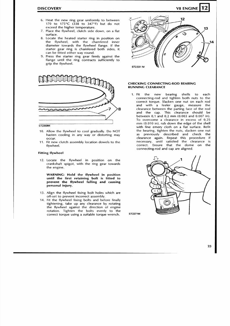
6. Heat the new ring gear uniformly to between
170 to 175OC (338 to 347°F) but do not
exceed the higher temperature.
7. Place the flywheel, clutch side down, on a flat
surface.
8. Locate the heated starter ring in position on
the flywheel, with the chamfered inner
diameter towards the flywheel flange. I f thestarter gear ring is chamfered both sides, it
can be fitted either way round.
9. Press the starter ring gear firmly against the
flange until the ring contracts sufficiently to
grip the flywheel.
10. Allow the flywheel to cool gradually. Do NOT
hasten cooling in any way or distorting mayoccur.
11 . Fit new clutch assembly location dowels to the
flywheel.
LDISCOVERY V8 ENGINE
Fitting flywheel
12
12. Locate the flywheel in position on the
crankshaft spigot, with the ring gear towards
the engine.
WARNING: Hold the flywheel in position
until the first retaining bolti s
fitted toprevent the flywheel falling and causingpersonal injury.
13 . Align the flywheel fixing bolt holes which are
off-set to prevent incorrect assembly.
14. Fit the flywheel fixing bolts and before finally
tightening, take up any clearance by rotating
the flywheel against the direction of engine
rotation. Tighten the bolts evenly to the
correct torque using a suitable torque wrench.
CHECKING CONNECTING-ROD BEARINGRUNNING CLEARANCE
1 . Fit the new bearing shells to each
connecting-rod and tighten both nuts to the
correct torque. Slacken one nut on each rod
and with a feeler gauge, measure the
clearance between the parting face of the rod
and the cap. This clearance should be
between 0 , l and 0,2 mm (0 .003 and 0.007 in).
To overcome a clearance in excess of 0,25
mm (0 .010 in), rub down the edge of the shell
with fine emery cloth on a flat surface. Refit
the bearing, tighten the nuts, slacken one nut
as previously described and check theclearance again. Repeat this procedure ifnecessary, until satisfied the clearance i s
correct. Ensure that the dome on the
connecting-rod and cap are aligned.
8/6/2019 V8 Overhaul
http://slidepdf.com/reader/full/v8-overhaul 24/45
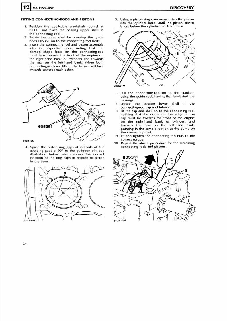
FllTlNG CONNECTING-RODS AND PISTONS
12
1. Position th e app licable crankshaft journal atB.D.C. nd place the bearing upper shell in
the connec t ing- rod .2. Retain the upper shell by screwing the guide
bol ts 605351 on t o the connect ing-rod bolts.
3. Insert the connecting-rod and piston assemblyinto its respective bore, noting that the
domed shape boss on the connec t ing- rodmust face towards the f ront of t h e e n g i n e o n
the right-hand bank of cylinders and towardsthe rear on the lef t -hand bank. When both
connecting-rods are fit ted, the bosses will faceinwards towards each other.
V8 ENGINE DISCOVERY
4. Space the piston ring gaps at intervals of 45"
avoiding gaps a t 90" to the gudgeon pin , seeillustration below which shows the correctposition of the ring caps in relation to pistonin the bore.
r
5. Using a piston ring com pres sor, tap the piston
into the cylinder bore, until the piston crown
. . is just below the cylinder block top face.
6. Pull the connecting-rod on to the crankpinusing the guide rods having first lubricated the
bearings.7. Locate the bearing lower shell in the
connect ing-rod c ap and lubricate .
8. Fit the cap a nd shell o n t o th e connect ing-rod,no t ic ing tha t the dome on the edge of th ecap must be towards the f ront of the engineon the right-hand bank of cylinders andtowards the rear on the left-hand bank,pointing in the same direct ion as the do m e on
the connec t ing- rod .9. Fit and tighten the conn ecting-rod nuts to the
correct torque.10. Repeat the above procedure for the remaining
connecting-rods and pistons.
8/6/2019 V8 Overhaul
http://slidepdf.com/reader/full/v8-overhaul 25/45
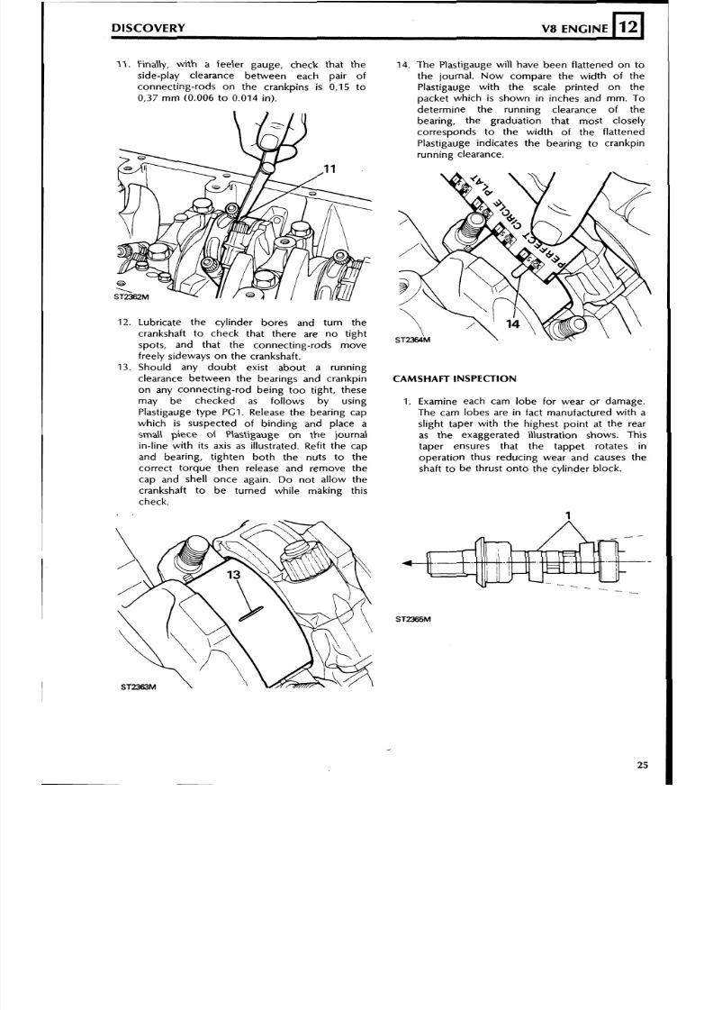
DISCOVERY V8 ENGINEn211. Finally, with a feeler gauge, check that the
side-play clearance between each pair of
connecting-rods on the crankpins is 0,15 to
0,37 mm (0.006 to 0.014 in).
Lubricate the cylinder bores and turn the
crankshaft to check that there are no tight
spots, and that the connecting-rods move
freely sideways on the crankshaft.
Should any doubt exist about a running
clearance between the bearings and crankpin
on any connecting-rod being too tight, these
may be checked as follows by using
Plastigauge type PG1. Release the bearing cap
which is suspected of binding and place a
small piece of Plastigauge on the journal
in-line with its axis as illustrated. Refit the cap
and bearing, tighten both the nuts to the
correct torque then release and remove the
cap and shell once again. Do not allow the
crankshaft to be turned while making this
check.
14. The Plastigauge will have been flattened on to
the journal. Now compare the width of the
Plastigauge with the scale printed on the
packet which is shown in inches and mm. To
determine the running clearance of the
bearing, the graduation that most closely
corresponds to the width of the flattened
Plastigauge indicates the bearing to crankpin
running clearance.
CAMSHAFT INSPECTION
1. Examine each cam lobe for wear or damage.
The cam lobes are in fact manufactured with a
slight taper with the highest point at the rear
as the exaggerated illustration shows. This
taper ensures that the tappet rotates in
operation thus reducing wear and causes the
shaft to be thrust onto the cylinder block.
8/6/2019 V8 Overhaul
http://slidepdf.com/reader/full/v8-overhaul 26/45
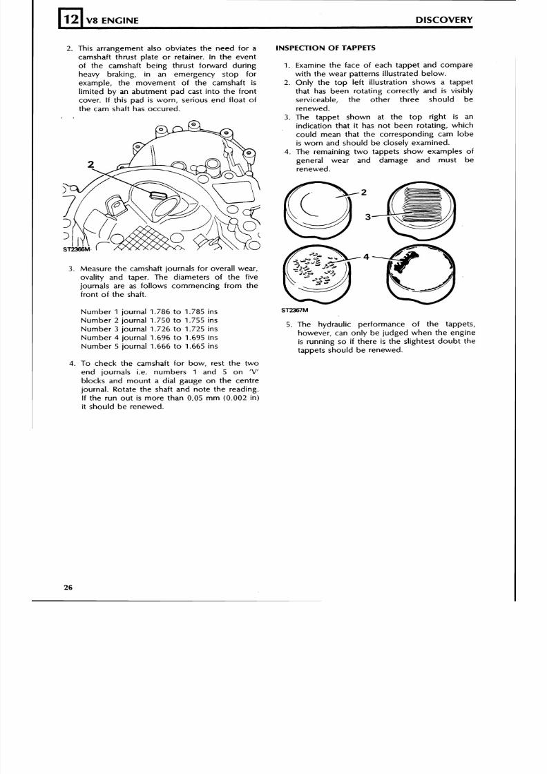
2. This arrangement also obviates the need for a
camshaft thrust plate or retainer. In the event
of the camshaft being thrust forward during
heavy braking, in an emergency stop for
example, the movement of the camshaft is
limited by an abutment pad cast into the front
cover. I f this pad i s worn, serious end float of
the cam shaft has occured.
12
3. Measure the camshaft journals for overall wear,
ovality and taper. The diameters of the five
journals are as follows commencing from the
front of the shaft.
V8 ENGINE DISCOVERY
Number 1 journal 1.786 to 1.785 ins
Number 2 journal 1.750 to 1.755 insNumber 3 journal 1.726 to 1.725 ins
Number 4 journal 1.696 to 1.695 ins
Number 5 journal 1.666 to 1.665 ins
.
4. To check the camshaft for bow, rest the two
end journals i.e. numbers 1 and 5 on 'V'
blocks and mount a dial gauge on the centre
journal. Rotate the shaft and note the reading.
If the run out i s more than 0,05 mm (0.002 in)
it should be renewed.
INSPECTION OF TAPPETS
1. Examine the face of each tappet and compare
with the wear patterns illustrated below.
2. Only the top left illustration shows a tappet
that has been rotating correctly and is visibly
serviceable, the other three should be
renewed.
3. The tappet shown at the top right is an
indication that it has not been rotating, which
could mean that the corresponding cam lobe
is worn and should be closely examined.
4. The remaining two tappets show examples of
general wear and damage and must be
renewed.
5 . The hydraulic performance of the tappets,
however, can only be judged when the engine
is running so i f there i s the slightest doubt the
tappets should be renewed.
8/6/2019 V8 Overhaul
http://slidepdf.com/reader/full/v8-overhaul 27/45
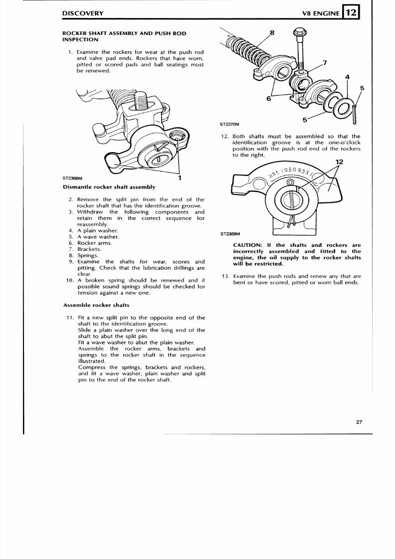
ROCKER SHAFT ASSEMBLY AND PUSH RODINSPECTION
DISCOVERY V8 ENGINE
1. Examine the rockers for wear at the push rod
and valve pad ends. Rockers that have worn,
pitted or scored pads and ball seatings must
be renewed.
12
12 . Both shafts must be assembled so that the
identification groove is at the one-o'clock
position with the push rod end of the rockers
to the right.
h
Dismantle rocker shaft assembly
2. Remove the split pin from the end of the
rocker shaft that has the identification groove.
3. Withdraw the following components and
retain them in the correct sequence for
reassembly.
4. A plain washer.5. A wave washer.
6. Rocker arms.
7. Brackets.
8. Springs.
9. Examine the shafts for wear, scores and
pitting. Check that the lubrication drillings are
clear.
10. A broken spring should be renewed and if
possible sound springs should be checked for
tension against a new one.
Assemble rocker shafts
11. Fit a new split pin to the opposite end of the
shaft to the identification groove.
Slide a plain washer over the long end of the
shaft to abut the split pin.
Fit a wave washer to abut the plain washer.
Assemble the rocker arms, brackets and
springs to the rocker shaft in the sequence
illustrated.
Compress the springs, brackets and rockers,
and fit a wave washer, plain washer and split
pin to the end of the rocker shaft.
CAUTION: If the shafts and rockers areincorrectly assembled and fitted to the
engine, the oil supply to the rocker shaftswill be restricted.
13. Examine the push rods and renew any that are
bent or have scored, pitted or worn ball ends.
8/6/2019 V8 Overhaul
http://slidepdf.com/reader/full/v8-overhaul 28/45
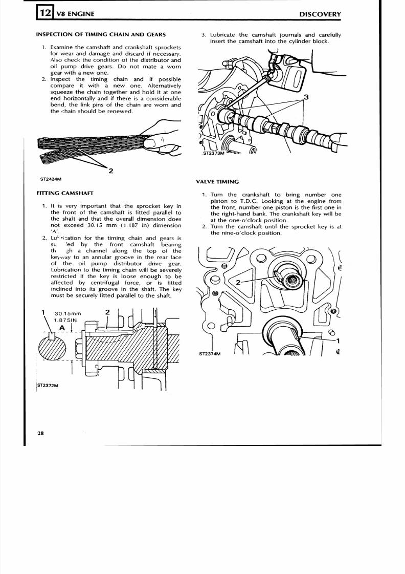
INSPECTION O F T IMIN G CHA IN AND GEARS
L
12
1. Examine the camshaft and crankshaft sprocketsfor wear and damage and discard if necessary.Also check the condition of the distributor andoil pump drive gears. Do not mate a worngear with a new one.
2. Inspect the timing chain and if possiblecompare it with a new one. Alternativelysqueeze the chain together and hold i t a t oneend horizontally and if there is a considerablebend, the link pins of the chain are worn andthe chain should b e renewe d.
V8 ENGINE DISCOVERY
FllTlN G CAMSHAFT
1. It is very important that the sprocket key inthe fro nt of th e cam sha ft is fitt ed parallel tothe shaft and that the overall dimension does
no t exceed 30.15 m m (1.187 in) dimension'A',
2. LuL".i:ation for th e timin g chain a nd g ear s isSL :t?d by the fro nt camshaft bearingth 3h a channel along the to p of th ekebway to an annular groove in the rear faceof the oil pump distributor drive gear.Lubrication to the timing chain will be severelyrestricted if the key is loose enough to beaffected by centrifugal force, or is fittedinclined into its groove in the shaft. The keymust be securely fitted parallel to the shaft.
3. Lubricate the camshaft journals and carefullyinsert the camshaft into the cylinder block.
VALVE TIMING
1. Turn the crankshaft to bring number onepiston t o T.D.C. Looking at th e engine fromthe front, number one piston is the first one inth e right-hand bank. The c ranks haft key will beat the one-o'clock position.
2. Turn the camshaft until the sprocket key is atthe nine-o'clock position.
8/6/2019 V8 Overhaul
http://slidepdf.com/reader/full/v8-overhaul 29/45
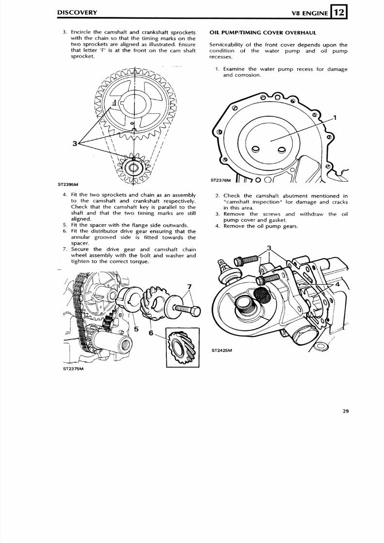
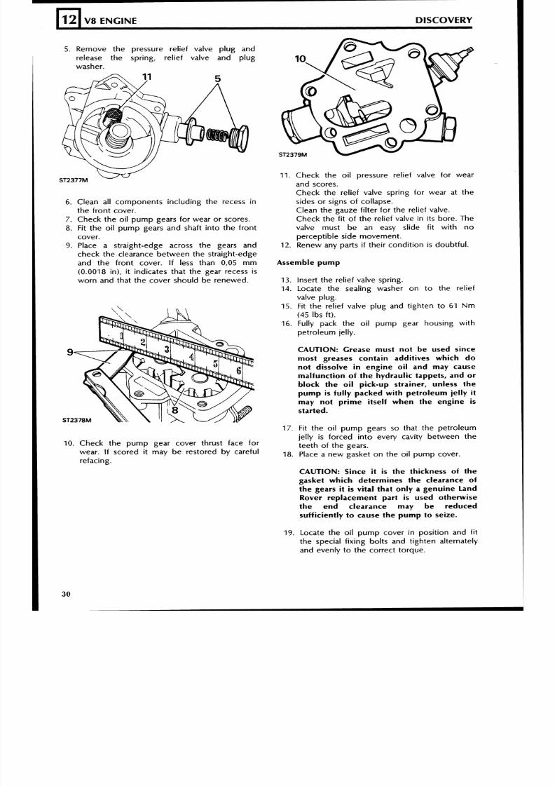
3. Encircle the camshaft and crankshaft sprockets O IL PU MP n lMlN G C O VER O VERH AU L
with the chain so that the timing marks on the
two sprockets are aligned as illustrated. Ensure Serviceability of the front cover depends upon the
that letter 'F' i s at the front on the cam shaft condit ion of the water pump and oil pump
sprocket. recesses.
DISCOVER Y V8 ENGINE
1. Examine the water pump recess for damage
and corrosion.
12
4. Fit the two sprockets and chain as an assembly 2. Check the camshaft abutment mentioned into the camshaft and crankshaft respectively. "camshaft inspection" for damage and cracksCheck that the camshaft key is parallel to the in this area.shaft and that the two timing marks are still 3. Remove the screws and withdraw the oil
aligned. pump cover and gasket.
5 . Fit the spacer with the flange side outwards. 4. Remove the oil pump gears.6. Fit the distributor drive gear ensuring that the
annular grooved side is fitted towards the
spacer.
7. Secure the drive gear and camshaft chain
wheel assembly with the bolt and washer and
tighten to the correct torque.
-
ST2425M
8/6/2019 V8 Overhaul
http://slidepdf.com/reader/full/v8-overhaul 30/45
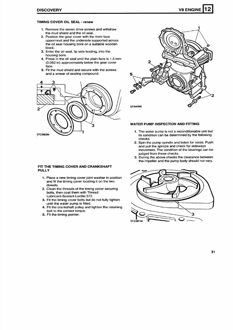
5. Remove the pressure rel ief valve plug and
release the spring, relief valve and plug
washer.
12
6. Clean al l components including the recess in
the f ron t cover.
7. Check the o i l p um p gears for wear or scores.8. Fit the oi l pu m p gears and shaft into the fron t
cover.9. Place a straight-edge across the gears and
check the clearance between the straight-edge
and the fro nt co ver. If less than 0,05 m m
(0.0018 in), it indicates that the gear recess is
worn and that the cover should be renewed.
J
V8 ENGINE DISCOVERY
10. Check the pump gear cover thrust face for
wear . I f scored i t may be restored by carefu l
refacing.
11. Check the oi l pressure rel ief valve for wear
and scores.
Check the relief valve spring for wear at the
sides or signs of collapse.
Clean the gauze filter for the relief valve.
Chec k the f i t o f th e rel ief valve i n i ts bore. Thevalve m ust b e an easy sl ide f i t with n o
percept ib le s ide m ovement .
12. Renew any parts if their cond it ion is doubtful.
Assemble pump
13. Insert the relief valve spring.
14. Locate the sealing washer on to the rel ief
valve plug.
15. Fit the rel ief valve pl ug and t ighten to 61 N m
(45 Ibs ft).
16. Ful ly pack the o i l pump gear housing wi thpetr oleu m jelly.
CAUTION: Grease must not be used since
most greases contain additives whi ch d o
not dissolve in engine oil and may cause
malfunction of the hydraulic tappets, and or
block the o il pick -up strainer, unless the
pu mp is fully packed wit h petroleum jelly it
may not prime itself when the engine is
started.
17. Fit the oi l pump gears so that the petroleum
jel ly is forced into every cavity between the
teeth of the gears.
18. Place a ne w gasket on the o i l pu m p cover.
CAUTION: Since i t is the thickness o f t he
gasket which determines the clearance of
the gears it is vital that only a genuine Land
Rover replacement part is used otherwise
the end clearance may be reduced
sufficiently t o cause the pu mp t o seize.
19. Locate the o i l pump cover in posi t ion and f i t
the special f ixing bolts and t ighten alternatelyand evenly to the correct torque.
8/6/2019 V8 Overhaul
http://slidepdf.com/reader/full/v8-overhaul 31/45
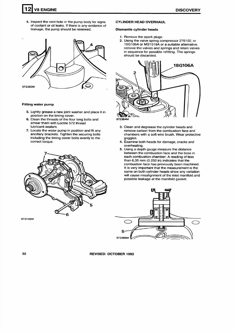
TIMING COVER OIL SEAL - renew
DISCOVERY V8 ENGINE
1. Remove the seven drive screws and withdraw
the mud shield and the oil seal.
2. Position the gear cover with the front face
uppermost and the underside supported across
the oil seal housing bore on a suitable woodenblock.
3. Enter the oil seal, lip side leading, into the
housing bore.
4. Press in the oil seal until the plain face is 1,5 mm
(0.062 in) approximately below the gear cover
face.
5. Fit the mud shield and secure with the screws
and a smear of sealing compound.
12
WATER PUMP INSPECTION AND FllTlNG
1. The water pump is not a reconditionable unit but
its condition can be determined by the followingchecks.
2. Spin the pump spindle and listen for noise. Push
and pull the spindle and check for sideways
movement. The condition of the bearings can be
judged from these checks.
3. During the above checks the clearance between
the impeller and the pump body should not vary.
FIT THE TIMING COVER AND CRANKSHAFT
PULLY
1. Place a new timing cover joint washer in position
and fit the timing cover locating it on the twodowels.
2. Clean the threads of the timing cover securing
bolts, then coat them with Thread
Lubricant-Sealant Loctite 572.
3. Fit the timing cover bolts but do not fully tighten
until the water pump is fitted.
4. Fit the crankshaft pulley and tighten the retaining
bolt to the correct torque.
5. Fit the timing pointer.
8/6/2019 V8 Overhaul
http://slidepdf.com/reader/full/v8-overhaul 32/45
4. Inspect the vent hole in the pump body for signs
of coolant or oil leaks. If there is any evidence of
leakage, the pump should be renewed.
12
Fitting water pump
V8 ENGINE DISCOVERY
5. tightly grease a new joint washer and place it in
position on the timing cover.
6. Clean the threads of the four long bolts and
smear them with Loctite 572 thread
lubricant-sealant.
7. Locate the water pump in position and fit any
ancillary brackets. Tighten the securing bolts
including the timing cover bolts evenly to thecorrect torque.
CYLINDER HEAD OVERHAUL
Dismantle cylinder heads
1. Remove the spark plugs.
2. Using the valve spring compressor 2761 02, or
18G106Aor MS1519A or a suitable alternative,remove the valves and springs and retain valves
in sequence for possible refitting. The springs
should be discarded.
3. Clean and degrease the cylinder heads and
remove carbon from the combustion face and
chambers with a soft wire brush. Wear protective
goggles.4. Examine both heads for damage, cracks and
overheating.
5. Using a depth gauge measure the distance
between the combustion face and the boss in
each combustion chamber.A reading of less
than 6,35 mm (0.250 in) indicates that the
combustion face has previously been machined.
It is very important that the measurement is the
same on both cylinder heads since any variation
will cause misalignment of the inlet manifold and
possible leakage at the manifold gasket.
REVISED: OCTOBER 1993
8/6/2019 V8 Overhaul
http://slidepdf.com/reader/full/v8-overhaul 33/45
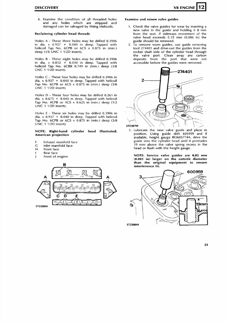
6. Examine the condit ion of al l threaded holes
and any holes which are s tr ipped and
damaged can b e salvaged b y f i t t ing Helicoils.
DISCOVERY V8 ENGINE
Reclaiming cylinder he ad threads
12
Holes A - These three holes may be dr i l led 0.3906
in dia. x 0.937 + 0.040 i n deep. Tapped withhelic oil Tap N o. 6CPB o r 6CS x 0.875 i n (rnin.)
deep (318 UNC 1 1/2 D insert) .
Ho les B - These eight holes may be dr i l led 0.3906
in dia. x 0.812 + 0.040 in deep. Tapped w ith
hel icoi l Tap No. 6CBB 0.749 i n (min.) d ee p (318
U N C 1 1/2D insert) .
Ho les C - These four holes may be dr i l led 0.3906 in
dia. x 0.937 + 0.040 i n deep. Tapped wit h hel icoi l
Tap N o . 6CPB o r 6CS x 0.875 in (rnin.) de ep (318
U N C 1 1/2D insert).
Ho les D - These fo ur h oles may be dr i l led 0.261 in
dia. x 0.675 + 0.040 in deep. Tapped with hel icoi lTap N o. 4CPB o r 4CS x 0.625 in (rnin.) de ep (112
U N C 1 112D insert).
Ho les E - These six holes may be dr i l led 0.3906 india. x 0.937 + 0.040 in deep. Tapped wi th he l icoi l
Tap N o. 6CPB o r 6CS x 0.875 i n (rnin.) de ep (318
U N C 1 112D insert).
NOTE: Right-hand cylinder head illustrated.American projection
F Exhaust ma nif old face
G In let manifo ld face
H Front face
I Rear face
J Front of e ngine
Examine and renew valve gui des
1 . Check the valve guides for wear by insert ing a
ne w va lve in the gu ide and ho ld ing i t 8 mm
from the seat. I f s ideways movement of the
valve head exceeds 0,15 m m (0.006 in) the
gu ide shou ld b e renewed.
2. To remove wo rn guides, use guide removingto ol 274401 and dr ive-out the guides f rom the
rocker shaft s ide of the cylinder head through
the valve port. Clean away any carbon
depos i ts f rom the por t tha t were not
accessible before the guides were removed.
3. Lubricate the new valve guide and place in
posit ion. Using guide dr if t 600959 and ifavailable, height gauge R0605774A, dr ive the
guide into the cy l inder head unt i l i t protrudes
19 m m abo ve th e valve spr ing recess in the
head or f lush with the height gauge.
NOTE: Service valve guides are 0,02 m m
(0.001 in) larger on the outside diameterthan the original equipment to ensureinterference fit.
8/6/2019 V8 Overhaul
http://slidepdf.com/reader/full/v8-overhaul 34/45
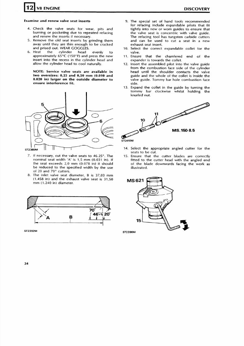
Examine and renew valve seat inserts
12
4. Check th e valve seats for wear, pits and
burn ing o r pocket ing due to repeated re fac ing
and r en ew the inserts if necessary.
5. Remove the ol d seat inser ts b y gr inding the m
away unt i l they are th in enoug h t o be c racked
and prised out. WEAR GOGGLES.6. Heat the cy l inder head evenly t o
approxim ately 65°C (150°F) and press the n e w
insert in to the recess in the cy l inder head a nd
al low the cy l inder head to co ol natural ly .
V8 ENGINE DISCOVERY
NOTE: Service valve seats are available in
two oversizes: 0,25 and 0,50 mm (0.010 and
0.020 in) larger on the outside d iameter to
ensure interference fit.
7. If necessary, cu t the valve seats t o 46.25". The
nominal seat width 'A' is 1,s m m (0.031 in). I f
the seat exceeds 2,O m m (0.078 in) it sh ou ld
be r educ ed to t he s peci fi ed w id th by t he use
of 20 and 70" cutters.
8. The in let valve seat diame ter, B is 37,03 m m
(1.458 in) and the exhaust valve seat is 31,50
m m (1.240 in) d iameter .
9. The spec ial set of hand tools recommended
for refacing include expandable pilots that f i t
t igh t ly in to new o r worn gu ides t o ensure tha t
the valve seat is concentr ic with valve guide.
The refacing tool has tungsten carbide cutters
and can be used to cu t a seat in a new
exhau st seat insert.
10. Select the correct expandable collet for thevalve.
11. Ensure that the chamfered end of the
expander is towards the collet.
12. insert the assembled pi lot in to the valve gu ide
from the combust ion face s ide of the cy l inder
head unt i l the shoulder contacts the valve
guide and the whole of the col let is ins ide the
valve guide. Tommy bar hole combust ion face
side.
13. Expand the col let in the guide b y turnin g thetom my bar c lockwise whi ls t ho ldin g the
knur led nut .
14. Select the appropriate angled cutter for the
seats to be cut .
15. Ensure that the cutter blades are correc tly
f i t ted to the cu t te r head w i th the ang led end
of the blade downwards fac ing the work as
illustrated.
8/6/2019 V8 Overhaul
http://slidepdf.com/reader/full/v8-overhaul 35/45
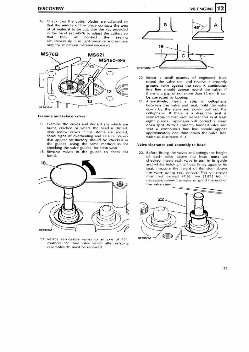
16. Check that the cutter blades are adjusted so
that the middle of the blade contacts the area
of o f material to b e cut. Use the key provided
in the hand set MS76 to adjust the cutters so
that they all contact the seating
simultaneously. Use light pressure and remove
only the minimum material necessary.
DISCOVERY V8 ENGINE
Examine and reface valves
L
12
17. Examine the valves and discard any which are
burnt, cracked or where the head is dished.
Also renew valves if the stems are scored,
show signs of overheating and seizure. Valves
that appear satisfactory should be checked in
the guides, using the same method as for
checking the valve guides, fo r stem wear.
18. Revolve valves i n the guides t o check for
bend.
20. Smear a small quantity o f engineers' blue
round the valve seat and revolve a properly
ground valve against the seat. A continuous
fine l ine should appear round the valve. if
there is a gap of not more than 12 mm it can
be corrected by lapping.
21. Alternatively, insert a strip of cellophane
between the valve and seat, ho ld the valve
do wn b y the stem and slowly pull out the
cellophane. If there is a drag the seal is
satisfactory in that spot. Repeat this in at least
eight places. Lapping-in will correct a small
open spot. With a correctly finished valve and
seat a continuous fine line should appear
approximately one third down the valve face
wi dt h as illustrated in 'C'.
Valve clearance and assembly to head
Before fitting the valves and springs the height
of each valve above the head must be
checked. insert each valve i n turn i n its guide
and whilst holding the head firmly agaianst its
seat, measure the height of the stem above
the valve spring seat surface. This dimension
must not exceed 47 ,63 mm (1.875 in). I f
necessary renew the valve or grind the end of
the valve stem.
19. Reface serviceable valves to an axle of 45",
example 'A'. Any valve which after refacingresembles 'B' must be renewed.
8/6/2019 V8 Overhaul
http://slidepdf.com/reader/full/v8-overhaul 36/45
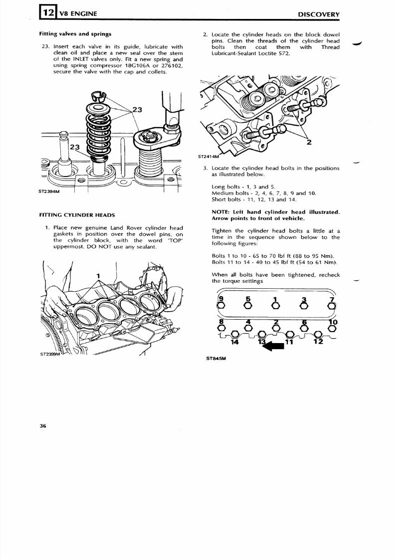
Fitting valves and springs
12
2 3 . Insert each valve in its guide, lubricate with
clean oil and p lace a new sea l over the s t emof the INLET valves only. Fit a new spring and
using spr ing compressor 18G106A o r 276102,
sec ure th e valve with th e ca p and col lets.
V8 ENGINE DISCOVERY
FllTlNG CYLINDER HEADS
z
1. Place new genuine Land Rover cylinder head
gaskets in pos i tion ov er the do we l pins , o nthe cyl inder block, wi th the word 'TOP'upperm os t . DO NOT use any sealant .
2. Locate the cyl inder heads on the block dowel
pins. Clean the threads of t he cyl inder headbol ts then coat them with ThreadLubricant-Sealant Loctite 572.
-.I
3. Locate the cylinder head bolts in the posit ionsas illustrated below.
Long bolts - 1, 3 and 5.
Medium bol ts - 2 , 4, 6, 7, 8, 9 an d 10.
Short bolts - 11, 12, 13 and 14.
NOTE: Left hand cylinder head illustrated.Arrow points to front of vehicle.
Tighten the cylinder head bolts a l i t t le at at i me i n t he s equence s how n be l ow t o t hefollowing figures:
Bolts 1 t o 10 - 65 t o 70 Ibf ft (88 t o 95 Nm).Bolts 11 t o 14 - 40 t o 45 Ibf f t (54 t o 61 Nm).
When al l bol ts have been t ightened, recheckthe torque set t ings d
8/6/2019 V8 Overhaul
http://slidepdf.com/reader/full/v8-overhaul 37/45
FITTING TAPPETS
DISCOVERY V8 ENGINE
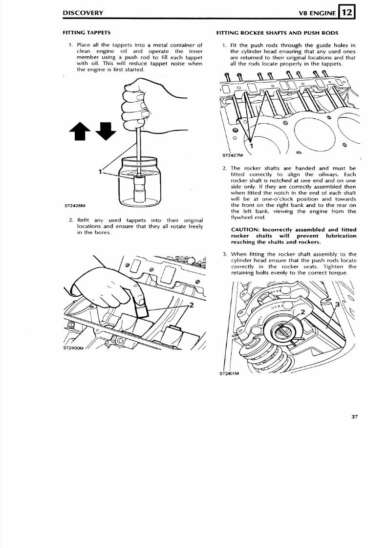
1 . Place all the tappets into a metal container of
clean engine oil and operate the inner
member using a push rod t o fill each tappet
with oil. This will reduce tappet noise when
the engine is first started.
12
2. Refit any used tappets into their original
locations and ensure that they all rotate freelyin the bores.
FITTING ROCKER SHAFTS AND PUSH RODS
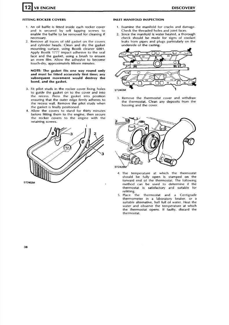
1. Fit the push rods through the guide holes in
the cylinder head ensuring that any used ones
are returned to their original locations and that
all the rods locate proper ly i n the tappets.
2. The rocker shafts are handed and must be
fit ted correctly t o align the oilways. Each
rocker shaft is notched at one end and on one
side only. If they are correctly assembled then
when fitted the notch i n the end o f each shaft
will be at one-o'clock posi tion and towards
the front on the right bank and t o the rear o n
the left bank, viewing the engine from the
flywheel end.
CAUTION: Incorrectly assembled and fitted
rocker shafts will prevent lubrication
reaching the shafts and rockers.
3. When fitting the rocker shaft assembly to the
cylinder head ensure that the push rods locate
correctly in the rocker seats. Tighten the
retaining bolts evenly t o the correct torque.
8/6/2019 V8 Overhaul
http://slidepdf.com/reader/full/v8-overhaul 38/45
FllTlNG ROCKER COVERS
L
12
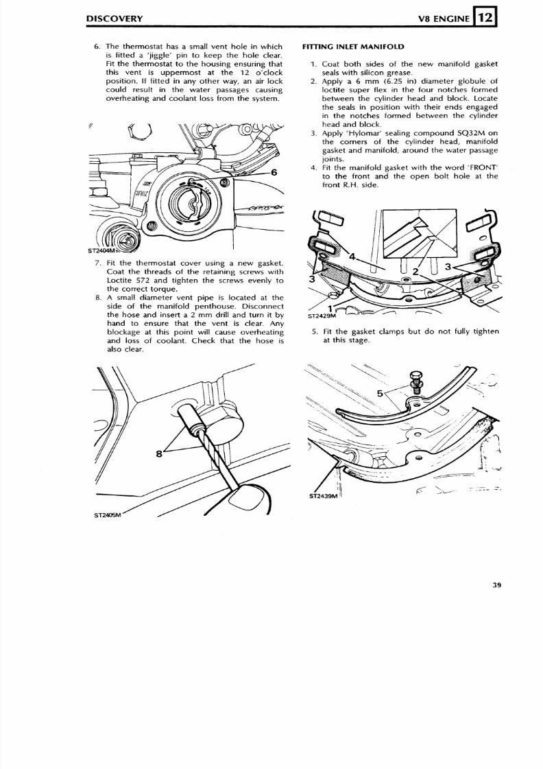
1. An oil baffle is f i t ted inside each rocker coverand is secured by self tapping screws toenable the baf fle t o b e r emov ed for cl eaning ifnecessary.
2. Remove all traces of old gasket on the cover s
and cyl inder heads . Clean and dry the gasketmounting surface, using Bostik cleaner 6001.
Apply Bost ik 177 7 impact adhes ive t o th e seal
face and the gasket , us ing a brush to ensurean even f i lm. Al low the adhes ive to become
touch-dry, approximately fif teen minutes.
V8 ENGINE DISCOVERY
NOTE: The gasket fits one way round only
and must be fitted accurately first time; any
subsequent movement would destroy the
bond, and the gasket.
3 . Fit pilot studs in the rocker cover fixing holest o gu i de t he gas ke t on t o t he cove r and i n t othe recess . Press the gasket into pos i t ionensuring tha t th e o uter e dg e f irmly adheres t othe recess wal l . Remove the pi lot s tuds when
the gasket is finally positioned.4. Allow the covers to stand for thirty minutes
before f it ting them to the engine , then secure
the rocker cover s to the engine wi th theretaining screw s.
INLET MANIFOLD INSPECTION
1. Examine the manifold for cracks and damage.
Check the threaded holes and joint faces .2. Since the manifold is water heated, a thorough
check should be made for s igns of coolantleaks from pipes and plugs particularly on the
unders ide of th e cas t ing.
3 . Remove the thermostat cover and wi thdrawthe thermostat . Clean any deposi ts f rom thehous ing and th e cover .
4. The temperature at which the thermostatshould be ful ly open is s tamped on the
forward end of the thermostat . The followingm et hod can b e us ed t o de te r m ine if t h ethermostat is satisfactory and suitable f o r
refitting.
5. Place the thermostat and a Cent igradethermometer in a laboratory beaker , or asuitable alternative, half full of water. Heat the
water and observe the temperature at whichthe thermos ta t opens . If faulty, discard thethermostat .
8/6/2019 V8 Overhaul
http://slidepdf.com/reader/full/v8-overhaul 39/45
6. The thermostat has a small vent ho le in whi ch
is fitted a 'jiggle' pin t o keep the hole clear.
Fit the thermostat t o the housing ensuring that
this vent is uppermost at the 12 o'clock
position. If fitted in any other way, an air lock
could result in the water passages causing
overheating and coolant loss from the system.
DISCOVERY V8 ENGINE
7. Fit the thermostat cover using a new gasket.
Coat the threads of the retaining screws with
Loctite 572 and tighten t he screws evenly t o
the correct torque.
8. A small diameter vent pipe is located at the
side of the manifold penthouse. Disconnect
the hose and insert a2
m m dril l and turn it byhand t o ensure that the vent is clear. Any
blockage at this point will cause overheating
and loss of coolant. Check that the hose is
also clear.
12
FllTlNG INLET MANIFOLD
1. Coat both sides of the new manifold gasket
seals with silicon grease.
2. Apply a 6 m m (6.25 in) diameter globule of
loctite super flex in the four notches formed
between the cylinder head and block. Locate
the seals in position with their ends engaged
in the notches formed between the cylinder
head and block.
3. Apply 'Hylomar' sealing compound SQ32M on
the corners of the cylinder head, manifold
gasket and manifold, around the water passage
joints.
4. Fit the manifold gasket wi th the wor d 'FRONT'
to the front and the open bolt hole at the
front R.H. side.
5. Fit the gasket clamps but do not fully tighten
at this stage.
8/6/2019 V8 Overhaul
http://slidepdf.com/reader/full/v8-overhaul 40/45
6 . Locate the manifold on to the cylinder head.
7. Clean the threads of the twelve manifold
securing bolts and apply Loctite 572 to the
threads.
8. Fit all the manifold bolts and tighten them a
little at a time, evenly, alternate sides working
from the centre to each end and finally tighten
to the correct torque. Note that the fourslotted headed bolts are fitted at the locations
'A'.
9. Tighten the gasket clamp bolts to the correct
12
FllT lNG THE DISTRIBUTOR
V8 ENGINE DISCOVERY
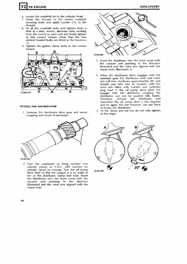
1. Examine the distributor drive gear and swivel
coupling and renew i f necessary.
2. Turn the crankshaft to bring number one
cylinder piston to T.D.C. with number si x
cylinder valves on overlap. Turn the oil pump
drive shaft so that the tongue i s at an angle of
60" to the distributor clamp bolt hole. Insert
the distributor into the front cover with the
vacuum unit pointing in the direction
illustrated and the rotor arm aligned with the
clamp hole.
3. Insert the distributor into the front cover with
the vacuum unit pointing in the direction
illustrated and the rotor arm aligned with the
clamp hole, illustration A.
4. When the distributor drive engages with the
camshaft gear the distributor shaft and rotor
arm will turn clockwise approximately 20 " and
should seat fully into its location with the
rotor arm inline with number one cyclinder
plug lead. If the oil pump drive does not
engage with the distributor coupling the
distributor can not be pushed fully home.
Therefore remove the distributor and
reposition the oil pump drive a few degrees
and try again. Do not however, use any force
to locate the distributor.
5. Fit the clamp and nut but do not fully tighten
at this stage.
8/6/2019 V8 Overhaul
http://slidepdf.com/reader/full/v8-overhaul 41/45
DISCOVERY V8 ENGINE 12
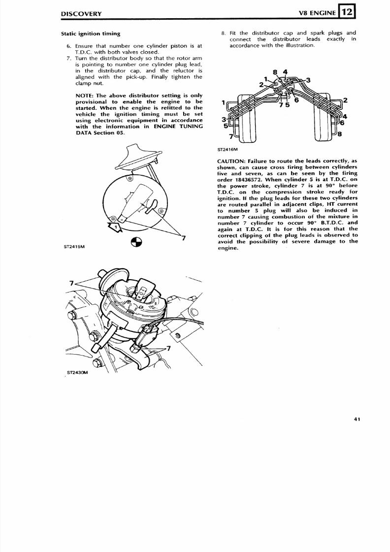
Static ignition timing
6. Ensure that number one cylinder piston i s at
T.D.C. with both valves closed.
7. Turn the distributor body so that the rotor arm
is pointing to number one cylinder plug lead,
in the distributor cap, and the reluctor is
aligned with the pick-up. Finally tighten theclamp nut.
NOTE: The above distributor setting is only
provisional to enable the engine to be
started. When the engine is refitted to the
vehicle the ignition timing must be set
using electronic equipment in accordance
with the information in ENGINE TUNING
DATA Section 05.
8. Fit the distributor cap and spark plugs and
connect the distributor leads exactly in
accordance with the illustration.
CAUTION: Failure t o route th e l eads correctly, as
shown, can cause cross firing between cylinders
five and seven, as can be seen by the firing
order 18436572. When cylinder 5 is at T.D.C. on
the power stroke, cylinder 7 is at 90" before
T.D.C. on th e compress ion st roke ready fo r
ignition. If the plug leads for these two cylinders
are routed parallel in adjacent clips, HT current
to number 5 plug will also be induced in
number 7 causing combustion of the mixture in
number 7 cylinder to occur 90" B.T.D.C. and
again at T.D.C. It is fo r this reason that t he
correct clipping of t he plug leads is observed t o
avoid the possibility of severe damage to the
engine.
8/6/2019 V8 Overhaul
http://slidepdf.com/reader/full/v8-overhaul 42/45
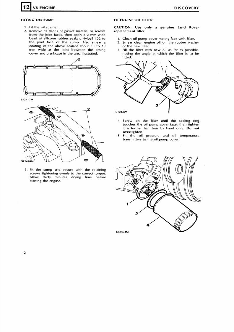
FITTING THE SUMP
12
1. Fit the oi l strainer.
2. Remove all traces o f gasket material or sealant
from the joint faces, then apply a 2 mm wide
bead o f silicone rubber sealant Hylosil 102 to
the joint face of the sump. Also smear a
coating o f the above sealant about 13 t o 19
m m wide at the joint between the timing
cover and crankcase i n the area illustrated.
V8 ENGINE DISCOVERY
3. Fit the sump and secure with the retaining
screws tightening evenly t o the correct torque.
Allow thirty minutes drying time before
starting the engine.
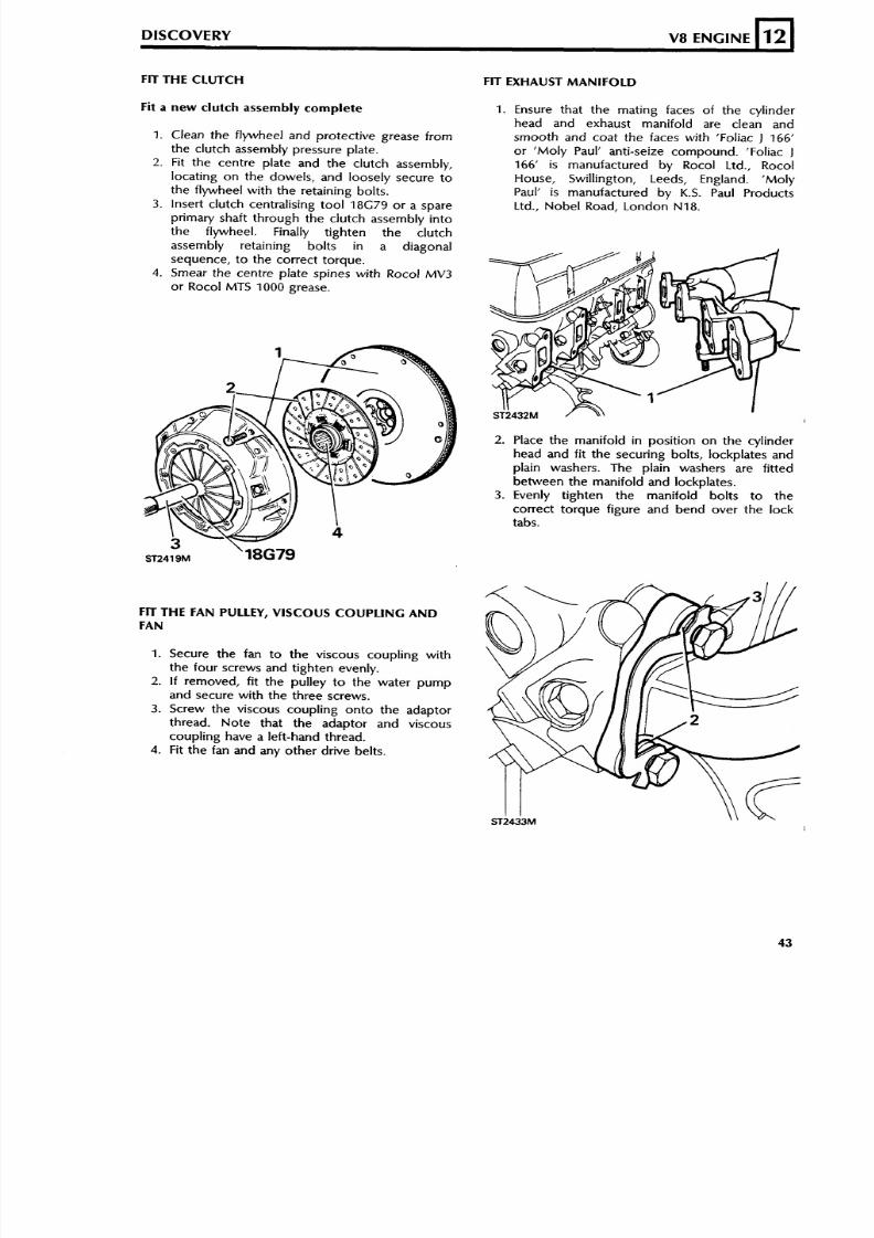
FIT ENGINE OIL FILTER
CAUTION: Use only a genuine Land Rover
replacement filter.
1. Clean oil pump cover mating face wit h filter.
2. Smear clean engine oil o n the rubber washer
of the new filter.
3. Fill the filter with new oil as far as possible,
noting the angle at which the filter is to be
fitted.
4. Screw o n the filter un til the sealing ring
touches the oil pump cover face, then tighten
it a further half turn by hand only. Do not
overtighten.
5. Fit the oil pressure and oil temperature
transmitters t o the oil pump cover.
8/6/2019 V8 Overhaul
http://slidepdf.com/reader/full/v8-overhaul 43/45
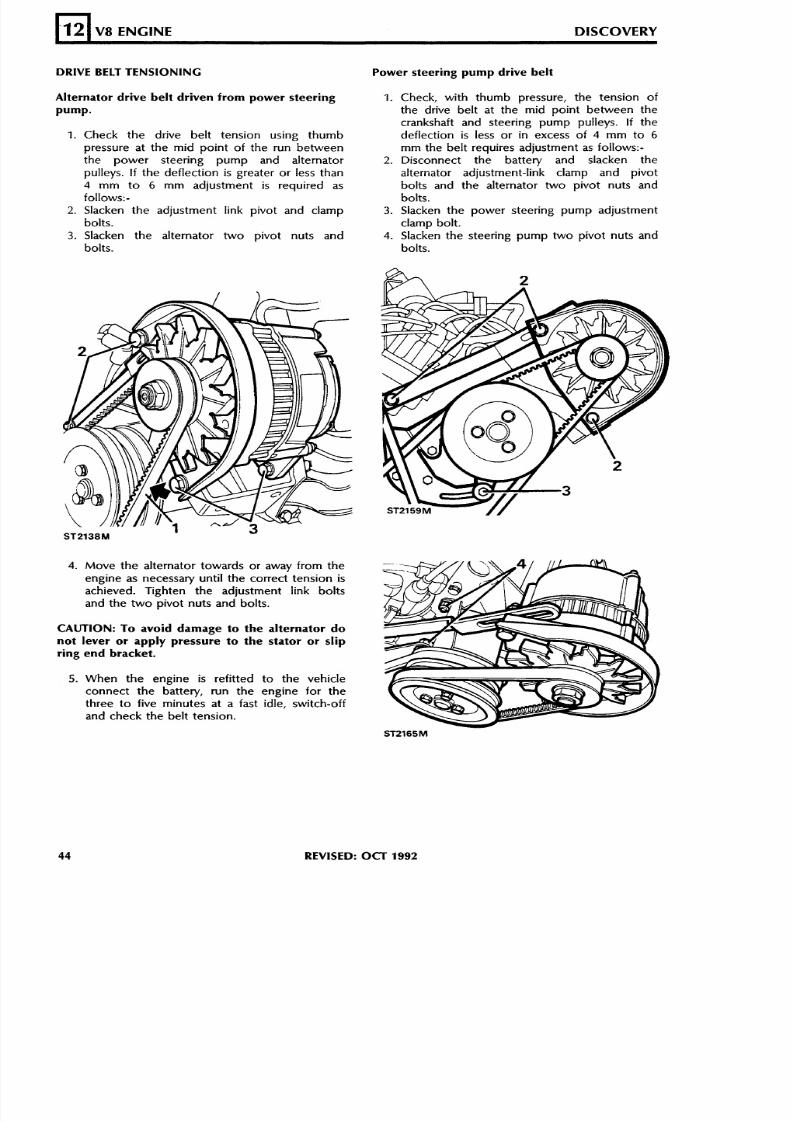
FIT THE CLUTCH
DISCOVERY V8 ENGINE
Fit a new clutch assembly complete
L
12
1. Clean the flywheel and protective grease fromthe clutch assembly pressure plate.
2. Fit the centre plate and the clutch assembly,locating on the dowels, and loosely secure tothe flywheel with the retaining bolts.
3. Insert clutch centralising tool 18G79 or a spareprimary shaft through the clutch assembly intothe flywheel. Finally tighten the clutchassembly retaining bolts in a diagonalsequence, to the correct torque.
4. Smear the centre plate spines with Rocol MV3
or Rocol MTS 1000 grease.
FIT THE FAN PULLEY, VISCOUS COUPLING AND
FAN
1. Secure the fan to the viscous coupling withthe four screws and tighten evenly.
2 . I fremoved, f i t the pulley t o the water pum pand secure with the three screws.
3. Screw the viscous coupling onto the adaptorthread. Note that the adaptor and viscouscoupling have a left-hand thread.
4. Fit th e fan and any oth er drive belts.
FIT EXHAUST MANIFOLD
1. Ensure that the mating faces of the cylinderhead and exhaust manifold are clean andsmooth and coat the faces with 'Foliac j 166'or 'Moly Paul' anti-seize compound. 'Foliac J
166' is manufactured by Rocol Ltd., RocolHouse, Swillington, Leeds, England. 'MolyPaul' is manufactured by K.S. Paul ProductsLtd., Nobel Road, London N18.
2. Place the manifold in position on the cylinderhead and fit the securing bolts, lockpiates andplain washers. The plain washers are fittedbetween the manifold and lockplates.
3 . Evenly tighten the manifold bolts to the
correct torque f igure and bend over the locktabs.
8/6/2019 V8 Overhaul
http://slidepdf.com/reader/full/v8-overhaul 44/45
IVE BELT TENSIONING
V8 ENGINE DISCOVERY
. Check the drive belt tension using thumbpressure at the mid point of the run betweenthe power steering pump and alternatorpulleys. If the deflection is greater or less than4 mm to 6 mm adjustment is required asfollows:-Slacken the adjustment link pivot and clampbolts.
. Slacken the alternator two pivot nuts andbolts.
Move the alternator towards or away from theengine as necessary until the correct tension isachieved. Tighten the adjustment link boltsand the two pivot nuts and bolts.
do
5. When th e engine is refitted t o the vehicleconnect the battery, run the engine for thethree to five minutes at a fast idle, switch-offand check th e belt tension.
Power steering pump drive belt
1 . Check, with thumb pressure, the tension ofthe drive belt at the mid point between thecrankshaft and steering pump pulleys. If thedeflection is less or in excess of 4 mm to 6
mm the belt requires adjustment as follows:-2. Disconnect the battery and slacken the
alternator adjustment-link clamp and pivotbolts and the alternator two pivot nuts andbolts.
3. Slacken the power steering pump adjustmentclamp bolt.
4. Slacken the steering pump two pivot nuts andbolts.
REVISED: OCT 1992
8/6/2019 V8 Overhaul
http://slidepdf.com/reader/full/v8-overhaul 45/45
5. Move the s teer ing pump in the requireddirection t o achieve th e correct tension.Tighten the link clamp and pivot bolts and thetwo pivot nuts and bolts.
DISCOVERY V8 ENGINE
CAUTION: Do not use a lever or apply pressure
to the pump body since this will cause
permanent damage to the pump.
12
6. Adjust the alternator drive belt.7. When the engine is ref i t ted to the vehicle
connec t th e ba ttery , run the engine for threet o five minute s at a fast idle, switch-off andcheck both the s teer ing pump and al ternatordrive belt tension.
NOTE: A positive drive tensioner is fitted to later
vehicles to provide greater accuracy when setting
power steering and alternator drive belts. The
tensioner eliminates the need to lever bothpower steering pump and alternator when
adjusting belt tension. See Section 10
Maintenance for details.
Fan drive belt (with Air Conditioning)
1. With thumb pressure , check the fan bel ttension at the mid point of the run be tweenthe fan and crankshaft pulleys on the side
opposi te the tensioning pul ley. If t h edeflection is less or greater than 4 m m t o 6
m m ad justm ent is nescessary as follows.
2. Disconnect the battery and slacken thetensioning pulley pinch bolt. Move the pulleyto the left o r r ight as required t o achieved th ecorrect tension and tighten the pinch bolt.
3. When the engine is refitted to the vehicleconnect the bat tery , run the engine for threeto five minutes at a fast idle, switch-off and
check the tension.
RUNNING ENGINE FOLLOWING OVERHAUL
CAUTION: If the rear crankshaft seal is new do
not exceed 1,000 engine revlmin when first
starting the engine, otherwise the seal will be
damaged.
I t should be noted that tappet noise can beexpected on initial starting-up after an overhaul due
t o oil drainage from the tappet assemblies orindeed if the vehicle has been standing over a verylong period. If excessive noise should be apparentafter an overhaul, the engine should be run at
approximately 2,500 revlmin for a few minutes(subject to the abov e caut ion) , when the noiseshould be eliminated.
Checking cylinder pressures
1. Run th e eng ine until normal opera ting
temperature is attained.2. Remove the spark plugs from all the cylinders.3. Secure the throttle in the fully open position
and check and note the pressure of each
cylinder in turn as follows: Insert a suitablepressure gauge, designed for the purpose,into a spark plug hole. Crank the engine with
the starter motor for several revolutions andmake a note of the highest figure recorded onthe gauge. Repeat th is procedure for theremaining cylinders. If the compression figuresare within 10% of each o the r the eng ine is
satisfactory. However, should the figures varyconsiderably mor e than 10% it indicates thatthe pistons and or valves are at fault. Lowpressure in adjoining cylinders could be due to