VA-9070 Series Electric Rotary Actuators for Two-Position and Modulating Service Technical Bulletin2
VA-9070 Series Electric Rotary Actuators for Two-Position and Modulating Service Technical Bulletin
IntroductionThe VA-9070 Series (Bray® Series 70) are quarter-turn, electric rotary actuators with manual override, designed for use on most Johnson Controls® VF Series Butterfly Valves sized for up to 6,500 lb·in (734.5 N·m) of torque. VA-9070 Series electric actuators cannot be used on the VF4000 and VF5000 Series Butterfly Valves with the M9000 Series Actuators. Operating speeds vary between 6 and 60 seconds.
Internal and External ComponentsThe VA-9070 Series actuator is divided into two internal sections: the power center below the switch plate and the control center above the switch plate. The power center (below the switch plate) contains the capacitor and gear motor, with its spur gear train. The power center drives a final non-backdriveable worm gear output. The power center also houses an override mechanism for manual operation. The control center (above the switch plate) has several user-accessible components: the camshaft assembly, limit switches, terminal strips, torque switches, heater, and servo.
On the outside of the actuator housing are adjustable mechanical travel stops, a large position indicator, the manual override handwheel, and dual conduit entry ports. The external coating is a polyester powder coat, providing resistance to Ultraviolet (UV) radiation exposure and chemical exposure.
Electrical OperationThe motor in the VA-9070 Series actuator is a permanent induction split capacitor design (single phase AC power). Travel limit switches are mechanical Form C Single-Pole, Double-Throw (SPDT) switches with two independent circuits. These SPDT switches are rated at 10 amperes (75 to 80% power factor), 1/2 hp 125 VAC, and 3/4 hp 250 VAC.
If the torque capacity of the actuator is exceeded to the point where the motor stalls and overheats, a thermal protector switch built into the motor windings automatically disconnects the motor power. Once the motor cools sufficiently, the thermal switch resets.
VA-9070 Series Electric Rotary Actuators for Two-Position and Modulating Service Technical Bulletin 3
Mechanical OperationMechanically, the ratio of the gear motor determines the speed of the actuator. The gear motor uses high-efficiency spur gears with different ratios for the different speeds. Initial gear reduction through the spur gears transfers to the worm shaft. The final gear reduction and output happens through a non-backdriveable worm gear set. An indicator-camshaft linked to the output shaft determines positioning. The manual override drives the worm shaft when engaged.
Manual Override OperationThe manual override operates similarly to the adjusting knob on a mechanical wristwatch. To engage the manual override, pull the handwheel to its outermost position. When the manual override engages, the actuator stops electrical operation.
A yellow position indicator provides visual indication that the manual override is engaged. Dry contacts on an internal switch can provide remote electrical indication of the override status.
Spring plungers hold the two handwheel positions (engaged and disengaged) in place. The handwheel remains in position until physically moved. Rotating the handwheel in a clockwise direction rotates the output shaft in the same clockwise (closed) direction. Rotating the handwheel in a counterclockwise direction rotates the output shaft in the same counterclockwise (open) direction.
Pre-installation StorageA temporary conduit entry plug, installed in shipped actuators, prevents foreign matter from entering the actuator. Store the actuator properly in a dry, temperature-controlled area to prevent moisture from entering through this temporary plug. Replace the temporary conduit plug with a permanent conduit plug if the actuator is stored for a long period of time or stored in adverse conditions. Prevent condensation from forming by maintaining a near constant external temperature and supplying power to the heater internal to the actuator.
Installation
MountingVA-9070 Series electric actuators are suitable for direct mounting on most Johnson Controls VF Series Butterfly Valves. VA-9070 Series Electric Actuators cannot be used on the VF4000 and VF5000 Series Butterfly Valves with the M9000 Series Actuators. Installing the VA-9070 Series actuator onto other quarter-turn valves or devices requires proper mounting hardware.
When mounting the actuator in the standard position, orient the actuator with its handwheel in a vertical plane and parallel to the pipeline. When mounting the actuator on a vertical pipe, position the actuator with the conduit entries on the bottom to prevent condensation from entering the actuator by way of the conduit. In all cases, position the conduit to prevent drainage into the actuator.
VA-9070 Series Electric Rotary Actuators for Two-Position and Modulating Service Technical Bulletin 4
Mount the actuator to the valve using the following procedure:
1. Manually operate the actuator until the output shaft of the actuator lines up with the valve stem. If possible, use an intermediate position, such as valve disc/stem and actuator half-open.
2. Place the proper sleeve adaptor (if required) onto the valve stem. Apply a small amount of grease to the sleeve adaptor to ease assembly.
3. Install the furnished mounting studs by threading them all the way into the actuator base. Insert the short, threaded length into the actuator.
4. Mount the actuator onto the valve stem. Be sure the mounting studs are properly aligned with the holes in the top plate of the valve or the mounting bracket. If necessary, manually override the actuator to align the mounting studs with the mounting holes.
5. Lower the actuator onto the valve and secure it tightly in place with the furnished hex nuts and lock washers.
WiringConnect the actuator to field wiring:
1. Remove the metal conduit plug for the power connection. Each actuator has two conduit entries (one for power and one for control).
2. Terminate all field wiring at the actuator terminal strip in accordance with the wiring diagrams attached to the inside of the actuator cover.
Note: The terminal strip accepts wire sizes ranging from 10 to 22 AWG (12 to 22 AWG for the servo). Do not use wire smaller than 18 AWG.
Note: The motor full load current is noted on the nameplate of the actuator.
Note: The heaters use approximately 0.5 amperes at 110 volts.
3. Properly seal the conduit connections to maintain the weatherproofed integrity of the actuator enclosure.
Note: The square-head conduit plug is weatherproofed but may eventually degrade. If the square-head conduit plug degrades, replace it with a metal plug.
Figure 1 shows typical field wiring for a two-position actuator, whereas Figure 2 shows typical field wiring for a modulating actuator.
VA-9070 Series Electric Rotary Actuators for Two-Position and Modulating Service Technical Bulletin 5
otary
O.
.O.
.C.
.C.
FIG
:wir_
htr_
aux
Figure 1: Typical Wiring Diagram of VA-9070 Series Two-Position Electric RActuator (Shown with Heater and Auxiliary Switches)
REDRED
BLUEBLUE
ABCD
CLOSE N.O.(VOLTAGE FREE)
OPEN N.O.(VOLTAGE FREE)
COM
COM
COM
N.
N
N.O.
N.O.
N.O.
N
N
N.C.
N.C.
N.C.
AUX OPEN
OPEN
GREENCAM
REDCAM
COM
CLOSE
AUX CLOSE
OVERRIDE SW
COM12
345678
9
YELLOW
BLUE
BLUE
BLUE
RED
RED
RED
YELLOW
HEATER (OPTIONAL)
GroundGround
Open
Close
For HeaterOnly
CloseOpen
Neutral
LiveBlueRed
Yellow orBlack
O C
NMotor
N.C. = Normally ClosedN.O. = Normally Open
VA-9070 Series Electric Rotary Actuators for Two-Position and Modulating Service Technical Bulletin 6
Figure 2: Typical Wiring Diagram of VA-9070 Series Modulating Electric Rotary Actuator (Shown with Heater)
Cal
ibra
teS
tatu
s
Inpu
t (-)
Inpu
t (+)
+5 V
OLT
SO
utpu
t (-)
Out
put (
+)
Mot
or C
lose
Mot
or O
pen
Neu
tral
Line
Neu
tral
Line
Pow
er
Com +5 Com
mon
CB
OP
EN
CB
CLO
SE
Com
mon
Han
dwhe
elC
omm
onO
P T
orqu
eC
L To
rque
Com
mon
Clo
se L
imit
Ope
n Li
mit
HTR
+5 V
DC
at 5
0 m
A(If
Req
uire
d)
- -+ +
Neu
tral
120
VAC
Gro
und
Out
goin
gFe
edba
ckS
igna
l1,2
Sin
gle
Pha
se
Supp
ly
Hea
ter
Inco
min
g C
omm
and
Sig
nal1
FIG
:fldw
rng
FUS
EOpen Speed
Close SpeedDeadband
ON12
345
678910
A B C D
WH
T
BLK
WH
T -
O
RN
GR
Y
+
Feed
back
Pot
entio
met
er
Gre
en
Cam
Red
Cam
N.O
.
N.O
.C
om
Com
Com
Com Com
N.O
.
N.O
.
N.O
.
N.C
.
N.C
.
N.C
.
Man
ual O
verr
ide
Sw
itch
Torq
ueS
witc
h
CLO
SE
OP
EN
BLU
RE
D
YLW
or
BLK
OC
NM
otor
YLW
YLW
BLU BLU
N.C
.
N.C
.
RE
DRE
D
4-20
mA
4-20
mA
0-5
V0-
5 V
0-10
V0-
10 V
2-10
V
ON
ON
ON
ON
ON
ON
ON O
N
ON
ON
ON
ON
ON
ON
OFF
OFF
OFF
OFF
OFF
OFF
OFF
OFF
OFF
OFF
OFF
OFF
OFF
OFF
OFF
Sw
itch
Sw
itch
Sw
itch
Sw
itch
Sw
itch
Sw
itch
CO
MM
AN
D IN
PUT
CO
MM
AN
D O
UTP
UT
14
25
36
RE
VE
RS
EA
CTI
NG
FOR
WAR
DA
CTI
NG
FAIL
DIS
ABL
EFA
ILE
NA
BLE
FAIL
C
LOS
EFA
ILO
PE
N
TOR
QU
E S
WE
NA
BLE
TOR
QU
E S
WD
ISA
BLE
9 10
7 8
1 - I
sola
te th
e co
mm
and
sign
al a
nd th
e fe
edba
ck s
igna
l fro
m e
ach
othe
r and
any
oth
er c
ircui
ts.
2 - T
he s
ervo
pow
ers
the
feed
back
loop
. Do
not s
uppl
y ex
tern
al p
ower
.
ORNORN
PRPPRP
VA-9070 Series Electric Rotary Actuators for Two-Position and Modulating Service Technical Bulletin 7
Multiple Actuator (Parallel) WiringUse a multiple pole switch to connect two VA-9070 Series electric actuators. See the Correct Wiring schematic in Figure 3.
Do not connect more than one actuator to a Single-Pole, Double-Throw (SPDT) switch. In the actuator, voltage is present on the non-powered motor winding (opposite to the powered motor winding). Connecting the voltage-containing, non-powered motor winding to another voltage-containing, non-powered motor winding interferes with the motor performance. See the Incorrect Wiring schematic in Figure 3.
Setup and AdjustmentTo set up and adjust the actuator, use the following procedure:
1. Set up and adjust the electrical travel switches and manual travel stops. See the Electrical Travel Switches and Manual Travel Stop Adjustments section in this document.
2. Set the input control signal. See the Setting the Input Control Signal section in this document.
3. Set the potentiometer. See the Setting the Potentiometer section in this document.
4. Set the servo. See the Setting the Servo section in this document.
Figure 3: Correct and Incorrect Wiring Schematics
Neutral Live
Open
Open
Motor Motor
Close
Close
DPDTSwitch
FieldWiring
Actuator A Actuator B
Neutral Live
Open
Open
Motor Motor
Close
Close
FieldWiring
SPDTSwitch
Actuator A Actuator B
Correct Wiring Incorrect Wiring
FIG
: wir_
crrc
t_in
crrc
t
VA-9070 Series Electric Rotary Actuators for Two-Position and Modulating Service Technical Bulletin 8
Electrical Travel Switches and Manual Travel Stop AdjustmentsYou must set the electrical travel switches to trigger prior to reaching the mechanical travel stops. The travel switches are labeled for open and close. The cams are color-coded (green for open; red for closed).
Manual travel stops are designed to prevent manual overtravel, not to stall the electric motor. The travel stops have an adjustment range of approximately 10 degrees.
Closed Travel Switch and Travel Stop Adjustment
1. Loosen the mechanical stop for the closed position and back it off so that it does not interfere with actuator travel. The closed stop is located on the right when viewed from the travel stop side of the actuator.
2. Remove the indicator rotor by pulling it up. This action exposes the machined groove on the end of the camshaft, which is the reference for the valve disc position.
3. Manually operate the actuator handwheel Clockwise (CW) until the valve reaches the desired closed position.
4. Rotate the red adjusting knob (by hand or with a flat-head screwdriver) until the cam lobe barely trips the switch from a CW direction.
Note: If the rotation of one cam moves the other cam, hold the other knobs or cams during adjustment.
5. With the travel switch in the closed position, rotate the handwheel one-half turn CW, then turn the closed travel stop CW until it stops against the output gear. Lock the travel stop bolts.
Figure 4: Setting the Travel Limit Switches
FIG
:set_
lim
VA-9070 Series Electric Rotary Actuators for Two-Position and Modulating Service Technical Bulletin 9
Open Travel Switch and Travel Stop Adjustment
Manually operate the actuator handwheel Counterclockwise (CCW) until the valve is fully open. Follow the same procedure as outlined in the Closed Travel Switch and Travel Stop Adjustment section, except use the green cam (open) and the travel stop located on the left side (as seen when viewed from the travel stop side of the actuator).
Setting the Input Control Signal
Set the input control signal for the input type used.
See Figure 2 for the location of the input control signal switches.
Setting the Potentiometer1. Manually operate the actuator handwheel until the unit is in the fully closed
position.
2. Rotate the black potentiometer drive gear adjustment knob to barely engage the potentiometer gear segment at the closed position.
3. Manually operate the actuator to the fully open position.
4. Fine-tune the potentiometer adjustment at this end to equalize the difference between the ends. The potentiometer gear segment should maintain engagement with the drive gear throughout full actuator travel.
Setting the Servo1. Wire the input signal to the incoming command signal terminals. Ensure that
you maintain proper polarity when making wiring connections.
2. Connect the power supply and activate the actuator.
3. Check the Status Light-Emitting Diode (LED).
• If the red Status LED is flashing, see the Servo Troubleshooting section.
• If the green Status LED is flashing, press and hold the CALIBRATE button until the green Status LED flashes rapidly (approximately 2 seconds), then release the CALIBRATE button. The servo drives the valve to the open and close travel limit switch settings. When the calibration is complete, the green Status LED resumes flashing at the normal rate.
• If the Status LED alternately flashes red, then flashes green, the calibration has failed. To resolve the problem, see the Servo Troubleshooting section.
Table 1: Input Control Signal Switch SettingsSwitch Input Signal
4-20 mA DC 0 to 5 V DC 0 to 10 V DC 2 to 10 V1 OFF ON ON ON
2 OFF OFF ON ON
3 OFF OFF OFF ON
VA-9070 Series Electric Rotary Actuators for Two-Position and Modulating Service Technical Bulletin 10
4. After calibration is complete, apply the desired minimum and maximum input signals and observe the actuator operation through one full cycle for proper operation.
Accessories
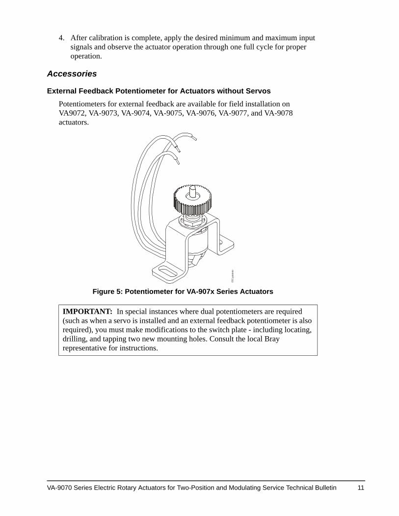
External Feedback Potentiometer for Actuators without Servos
Potentiometers for external feedback are available for field installation on VA9072, VA-9073, VA-9074, VA-9075, VA-9076, VA-9077, and VA-9078 actuators.
IMPORTANT: In special instances where dual potentiometers are required (such as when a servo is installed and an external feedback potentiometer is also required), you must make modifications to the switch plate - including locating, drilling, and tapping two new mounting holes. Consult the local Bray representative for instructions.
FIG
:ptn
tmtr
Figure 5: Potentiometer for VA-907x Series Actuators
VA-9070 Series Electric Rotary Actuators for Two-Position and Modulating Service Technical Bulletin 11
Contents of the Feedback Potentiometer Kit
• one potentiometer assembly
• two No. 6 cross-drive pan-head screws
• two No. 6 internal lock washers
• one 10-point terminal strip
• one terminal strip marker for auxiliary switches and/or feedback potentiometer
• one small wiring diagram sticker for the additional potentiometer
Tools Required
For terminal wiring: 3/16 in. (5 mm) blade screwdriver
For potentiometer mounting screws: No. 2 Phillips screwdriver
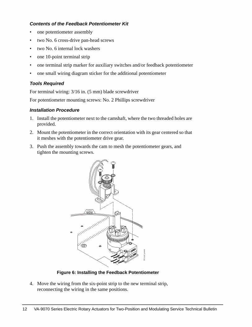
Installation Procedure
1. Install the potentiometer next to the camshaft, where the two threaded holes are provided.
2. Mount the potentiometer in the correct orientation with its gear centered so that it meshes with the potentiometer drive gear.
3. Push the assembly towards the cam to mesh the potentiometer gears, and tighten the mounting screws.
4. Move the wiring from the six-point strip to the new terminal strip, reconnecting the wiring in the same positions.
FIG
:instl
_ptn
tmtr
Figure 6: Installing the Feedback Potentiometer
VA-9070 Series Electric Rotary Actuators for Two-Position and Modulating Service Technical Bulletin 12
.
y.
.
try angle
torque
cal Bray
.
tting prior to
r.
peration of
5. Wire the potentiometer to the terminal strip using the small stick-on wiring diagram provided.
6. Adhere the wiring diagram sticker to the inside of the cover.
Setting the Potentiometer
1. Manually operate the actuator handwheel until the unit is in the fully closed position.
2. Rotate the black potentiometer drive gear adjustment knob to barely engage the potentiometer gear segment at the closed position.
3. Manually operate the actuator to the fully open position.
4. Fine-tune the potentiometer adjustment at this end to equalize the difference between the ends. The potentiometer gear segment should remain engaged with the drive gear throughout full actuator travel.
Troubleshooting Procedures
Actuator TroubleshootingSee Table 2 for actuator troubleshooting information.Table 2: Actuator Troubleshooting Chart (Part 1 of 2)Problem Possible Cause SolutionActuator does not operate.
Override is engaged. Push handwheel in all the way
Wiring is incorrect. Check wiring and power suppl
Actuator has reached its thermal shutdown temperature.
Allow time to cool.
Actuator operates in reverse directions.
Field wiring is reversed. Rewire field wiring.
Actuator does not fully close valve.
Limit switches are tripping. Readjust travel limit switches.
Mechanical travel stop is stopping actuator. Adjust mechanical travel stops
Valve torque requirement is higher than actuator output.
Manually override out of seat; seating or larger actuator.
Optional torque switches are tripping. Valve torque exceeds actuatorrating; consult the local Bray representative.
Voltage power supply is low. Resize actuator; consult the lorepresentative.
Mechanical travel stop is stopping actuator. Adjust mechanical travel stops
Optional torque switches are tripping. Mechanical travel stops are hielectrical limit switch.
High valve torque. Obtain higher capacity actuato
Engaging override handwheel does not shut off motor.
Override pin is corroded or damaged. Clean and check for smooth othe override switch pin.
Override switch is damaged. Replace switch.
VA-9070 Series Electric Rotary Actuators for Two-Position and Modulating Service Technical Bulletin 13
ossible so
ect; adjust .
e constant
ater entry
.
gear to
es for less
r 90 degrees
degrees of
r 90 degrees
ter gear.
use rate servo.
see wiring
rom these
use the rate the
Servo TroubleshootingThe Status LED is a bicolor (red or green) LED that provides information on the operation of the servo. Whenever the LED flashes green, the servo operates, although it may not operate at optimal levels. Whenever the LED flashes red, the servo does not operate. The servo uses sequences of flashes to give troubleshooting indications. See Table 3.
Disengaging override handwheel does not restart motor.
Not completely disengaged. Push handwheel in as far as pthat no yellow shows.
Override pin is damaged and does not trigger switch.
Replace override pin.
Incorrect wiring of override switch. Check wiring.
Motor runs but worm and gear segment do not run.
Worm gear segment is not meshing with worm.
Remove switch plate and insptravel stops to prevent problem
Corrosion inside actuator.
Condensation forming. Test heater wiring; should havpower.
Water leaking in. Check all seals and possible wthrough conduit.
Actuator moves back and forth near set point (hunts).
Signal has interference. Shield signal from interference
Potentiometer gear disengages from potentiometer drive gear.
Potentiometer gear was not meshed correctly.
Adjust the potentiometer drivemaintain engagement.
Actuator is electrically operating beyond the 90 degree travel limit.
Set electrical travel limit switchthan 90 degrees of operation.
Actuator has been manually operated beyond the 90 degree travel limit.
Set mechanical travel limits foof operation.
Actuator does not travel fully open or fully closed.
Travel limit switches are not set correctly. Set travel limit switches for 90operation.
Mechanical travel stops are not set correctly.
Set mechanical travel stops foof operation.
Actuator motor does not run and yellow servo power light is off.
Power is disconnected. Reconnect power.
Actuator does not properly respond to command signal.
Potentiometer gear is not engaged. Engage and adjust potentiome
Command signal jumper position is not correct. Jumper is missing or should be installed.
Install or remove jumper. ThenAutocalibrate button to recalib
Actuator runs in one direction only.
Wiring is incorrect. Inspect and correct wiring.
Potentiometer is wired backwards. Reverse black and gray wires;diagram inside cover.
Limit switch or torque switch is triggered. Ensure connections to servo fswitches are shorted.
Command signal jumper position is not correct. Jumper is missing or should be installed.
Install or remove jumper. ThenAutocalibrate button to recalibservo.
Table 2: Actuator Troubleshooting Chart (Part 2 of 2)Problem Possible Cause Solution
VA-9070 Series Electric Rotary Actuators for Two-Position and Modulating Service Technical Bulletin 14
cept for
h Flash 8unlit
unlit
unlit
unlit
unlit
unlit
green
unlit
unlit
unlit
unlit
unlit
unlit
unlit
red
green
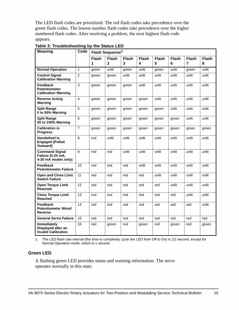
The LED flash codes are prioritized. The red flash codes take precedence over the green flash codes. The lowest number flash codes take precedence over the higher numbered flash codes. After resolving a problem, the next highest flash code appears.
Green LEDA flashing green LED provides status and warning information. The servo operates normally in this state.
Table 3: Troubleshooting by the Status LED Meaning Code Flash Sequence1
1. The LED flash rate interval (the time to completely cycle the LED from Off to On) is 1/2 second, exNormal Operation mode, which is 1 second.
Flash 1
Flash 2
Flash 3
Flash 4
Flash 5
Flash 6
Flas7
Normal Operation 1 green unlit green unlit green unlit green
Control Signal Calibration Warning
2 green green unlit unlit unlit unlit unlit
Feedback Potentiometer Calibration Warning
3 green green green unlit unlit unlit unlit
Reverse Acting Warning
4 green green green green unlit unlit unlit
Split Range 0 to 50% Warning
5 green green green green green unlit unlit
Split Range 50 to 100% Warning
6 green green green green green green unlit
Calibration in Progress
7 green green green green green green green
Handwheel Is Engaged (Pulled Outward)
8 red unlit unlit unlit unlit unlit unlit
Command Signal Failure (0-20 mA, 4-20 mA modes only)
9 red red unlit unlit unlit unlit unlit
Feedback Potentiometer Failure
10 red red red unlit unlit unlit unlit
Open and Close Limit Switch Failure
11 red red red red unlit unlit unlit
Open Torque Limit Reached
12 red red red red red unlit unlit
Close Torque Limit Reached
13 red red red red red red unlit
Feedback Potentiometer Wired Reverse
14 red red red red red red red
General Servo Failure 15 red red red red red red red
Immediately Displayed after an Invalid Calibration
16 red green red green red green red
VA-9070 Series Electric Rotary Actuators for Two-Position and Modulating Service Technical Bulletin 15
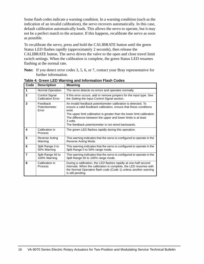
Some flash codes indicate a warning condition. In a warning condition (such as the indication of an invalid calibration), the servo recovers automatically. In this case, default calibration automatically loads. This allows the servo to operate, but it may not be a perfect match to the actuator. If this happens, recalibrate the servo as soon as possible.
To recalibrate the servo, press and hold the CALIBRATE button until the green Status LED flashes rapidly (approximately 2 seconds), then release the CALIBRATE button. The servo drives the valve to the open and close travel limit switch settings. When the calibration is complete, the green Status LED resumes flashing at the normal rate.
Note: If you detect error codes 3, 5, 6, or 7, contact your Bray representative for further information.
Table 4: Green LED Warning and Information Flash Codes Code Description Meaning1 Normal Operation The servo detects no errors and operates normally.
2 Control Signal Calibration Error
If this error occurs, add or remove jumpers for the input type. See the Setting the Input Control Signal section.
3 Feedback Potentiometer Error
An invalid feedback potentiometer calibration is detected. To ensure a valid feedback calibration, ensure that these conditions exist.The upper limit calibration is greater than the lower limit calibration.The difference between the upper and lower limits is at least 3 volts.The feedback potentiometer is not wired backwards.
4 Calibration in Process
The green LED flashes rapidly during this operation.
5 Reverse Acting Warning
This warning indicates that the servo is configured to operate in the Reverse Acting Mode.
6 Split Range 0 to 50% Warning
This warning indicates that the servo is configured to operate in the Split Range 0 to 50% range mode.
7 Split Range 50 to 100% Warning
This warning indicates that the servo is configured to operate in the Split Range 50 to 100% range mode.
8 Calibration in Process
During a calibration, the LED flashes rapidly at one-half second intervals. When the calibration is complete, the LED resumes with the Normal Operation flash code (Code 1) unless another warning is still pending.
VA-9070 Series Electric Rotary Actuators for Two-Position and Modulating Service Technical Bulletin 16
Red LEDA flashing red LED indicates a fault condition that prevents the actuator from operating. Correct the fault condition to allow the actuator to resume operating. If you detect error Code 16, contact your Bray representative for further information.Table 5: Red LED Warning and Information Flash Codes Code Description Meaning9 Handwheel Is Engaged
(Pulled Outward)When the handwheel is engaged, the servo can only be operated manually. This error also occurs if the handwheel switch is incorrectly connected to the servo.
10 Command Signal Failure
When the servo is configured to operate in the 0 to 20 mA mode, an input greater than 20 mA triggers an error. When the handwheel is configured to run in 4 to 20 mA operating mode, an input less than 4 mA or greater than 20 mA triggers an error. The Command Signal is not checked in the 0 to 10 V mode.
11 Feedback Potentiometer Failure
If the feedback potentiometer cannot be detected, or if in the fully closed or fully open position and the feedback potentiometer is at the end of its travel, an error is detected.
12 Open and Close Limit Switch Failure
When both the open and close limit switches are open-circuited at the same time, an error is detected.
13 Open Torque Limit Reached
The open torque limit switch has been tripped or the open torque limit switch is incorrectly connected to the servo.
14 Close Torque Limit Reached
The close torque limit switch has been tripped or the close torque limit switch is incorrectly connected to the servo.
15 Feedback Potentiometer Wired in Reverse
This check is made only during the servo autocalibration. The feedback potentiometer is wired in reverse when, at the completion of the calibration, the feedback potentiometer value at the fully open position is less than the value at the fully closed position. To clear the error, turn off the power to the servo, correct the feedback potentiometer wiring, turn on the power to the servo, and complete the autocalibration.
16 General Servo Failure If after cycling the power to the servo, this error persists, contact your local Bray representative for assistance.
17 Calibration Error This flash code is displayed after a failed calibration for 3 seconds. See Code 2 and Code 3 in Table 4 for more information.
VA-9070 Series Electric Rotary Actuators for Two-Position and Modulating Service Technical Bulletin 17
Disassembly and Assembly
General InformationVA-9070 Series actuators are differentiated into three groups, according to size:
• VA-9072 actuators
• VA-9073, VA-9074, and VA-9075 actuators
• VA-9076, VA-9077, and VA-9078 actuators
Tools Required Table 6: Basic Tools Common to All Actuators Item ToolTerminal Connections, Cam Adjustment Screwdriver, 3 to 4 Tip Blade
Servo Trimmer Potentiometers Screwdriver, Blade for Trim Potentiometers
Table 7: Basic Tools for VA-9072 Actuators Item ToolMounting Nuts Wrench, 1/2 in. (13 mm)
Cover Captivated Cap Screws Hex Key, 1/4 in. (6 mm)
Travel Stop Adjusting Studs Hex Wrench, 1/8 in. (3 mm)
Travel Stop Jam Nuts Wrench, 7/16 in. (11 mm)
Motor Mount Socket Flat-Head Cap Screw Hex Key, 3/32 in. (2 mm)
Motor Mount Socket-Head Cap Screw Hex Key, 9/64 in. (4 mm)
Table 8: Basic Tools for VA-9073, VA-9074, and VA-9075 Actuators Item ToolMounting Nuts (Small Pattern), Travel Stop Jam Nuts
Wrench, 1/2 in. (13 mm)
Mounting Nuts (Large Pattern) Wrench, 3/4 in. (19 mm)
Cover Captivated Cap Screws Hex Key, 5/16 in. (8 mm)
Travel Stop Adjusting Studs Hex Key, 3/16 in. (5 mm)
Motor Mount Socket-Head Cap Screw Hex Key, 5/32 in. (4 mm)
Table 9: Basic Tools for VA-9076, VA-9077, and VA-9078 Actuators Item ToolMounting Nuts, Travel Stop Jam Nuts Wrench, 3/4 in. (19 mm)
Cover Captivated Cap Screws Hex Key, 3/8 in. (10 mm)
Travel Stop Adjusting Studs Hex Key, 1/4 in. (6 mm)
Motor Mount Socket-Head Shoulder Bolt Hex Key, 5/32 in. (4 mm)
Motor Mount Socket-Head Cap Screws Hex Key, 3/16 in. (5 mm)
VA-9070 Series Electric Rotary Actuators for Two-Position and Modulating Service Technical Bulletin 18
Procedure for VA-9072 Actuators1. Disconnect all power to the actuator and remove the cover. See Figure 7.
2. Disconnect the motor wires from the main terminal block (motor close, motor open, and neutral).
Figure 7: Two-Position Actuator with Cover Removed
FIG
F:ac
ttr_n
o cv
r
VA-9070 Series Electric Rotary Actuators for Two-Position and Modulating Service Technical Bulletin 19
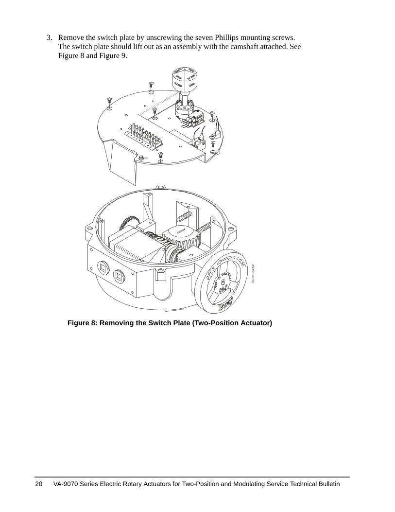
3. Remove the switch plate by unscrewing the seven Phillips mounting screws. The switch plate should lift out as an assembly with the camshaft attached. See Figure 8 and Figure 9.
FIG
:rmv_
swtc
hplt
Figure 8: Removing the Switch Plate (Two-Position Actuator)
VA-9070 Series Electric Rotary Actuators for Two-Position and Modulating Service Technical Bulletin 20
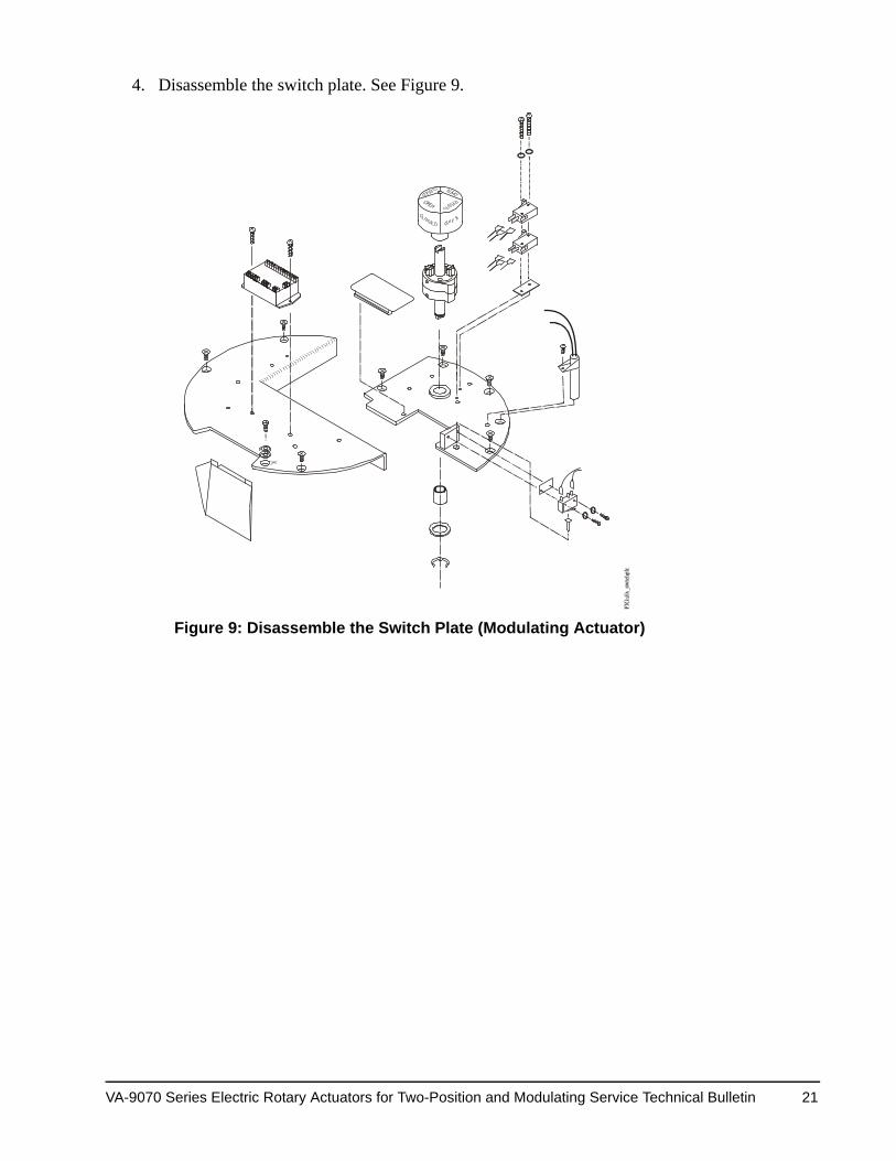
4. Disassemble the switch plate. See Figure 9.
Figure 9: Disassemble the Switch Plate (Modulating Actuator)
VA-9070 Series Electric Rotary Actuators for Two-Position and Modulating Service Technical Bulletin 21
5. Disconnect the motor leads that run to the capacitor (plug-in connectors), and then unscrew the three mounting screws (two lower and one upper). See Figure 10.
6. Vertically remove the gear motor out of the actuator. See Figure 10. Do not misplace the alignment pin.
FIG
:rmv_
mtr
Figure 10: Removing the Motor
VA-9070 Series Electric Rotary Actuators for Two-Position and Modulating Service Technical Bulletin 22
7. To remove the worm shaft spur gear, remove the spring pin using a 3/32 in. (2 mm) punch, then slide the gear off the end of the worm shaft. See Figure 11.
8. To remove the output drive worm gear, back off both mechanical travel stops. Manually override the worm gear until it disengages the worm. Remove the retaining ring and thrust washer, then lift the output drive worm gear out of its bushing. See Figure 11.
9. Remove the capacitor. See Figure 10.
Note: A spring pin holds the handwheel in place. Further disassembly of the actuator requires special tools and procedures and is not covered in this document.
The reassembly procedure is the opposite of the disassembly procedure.
FIG
:dis_
actr_
fnl
Figure 11: Disassembling the Actuator
VA-9070 Series Electric Rotary Actuators for Two-Position and Modulating Service Technical Bulletin 23
Procedure for VA-9073, VA-9074, VA-9075, VA-9076, VA-9077, and VA-9078 Actuators
1. Disconnect all power to the actuator and remove the cover. See Figure 12.
2. Remove the field wiring and the internal motor wiring from the terminal strips. See Figure 13.
Figure 12: Two-Position Actuator with Cover Removed
FIG
:lg_n
ocvr
Figure 13: Removing the Switch Plate (Two Position Actuator)
FIG
:Lg_
swtc
hplt
VA-9070 Series Electric Rotary Actuators for Two-Position and Modulating Service Technical Bulletin 24
3. Remove the switch plate by unscrewing the seven Phillips-head mounting screws and then pull up on the switch plate to remove it. See Figure 14.
FIG
:Lg_
rmvd
Figure 14: Two-Position Actuator with Switch Plate Removed
VA-9070 Series Electric Rotary Actuators for Two-Position and Modulating Service Technical Bulletin 25
4. Disconnect the motor leads that run to the capacitor. See Figure 15.
5. Unscrew the mounting screws. See Figure 15.
Note: The VA-9072 Series Actuator has two lower mounting screws and one upper mounting screw. The VA-9073 through VA-9075 Series Actuators have four lower mounting screws and one upper mounting screw. The VA-9076 through VA-9078 Series Actuators have four lower mounting screws, one upper mounting screw, and one lower locating screw.
6. Remove the motor vertically out of the actuator. See Figure 15.
Note: Do not misplace the alignment pin.
FIG
:lg_m
tr_rm
vl
Figure 15: Removing the Motor
VA-9070 Series Electric Rotary Actuators for Two-Position and Modulating Service Technical Bulletin 26
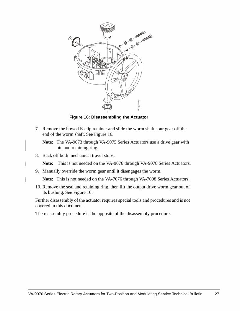
7. Remove the bowed E-clip retainer and slide the worm shaft spur gear off the end of the worm shaft. See Figure 16.
Note: The VA-9073 through VA-9075 Series Actuators use a drive gear with pin and retaining ring.
8. Back off both mechanical travel stops.
Note: This is not needed on the VA-9076 through VA-9078 Series Actuators.
9. Manually override the worm gear until it disengages the worm.
Note: This is not needed on the VA-7076 through VA-7098 Series Actuators.
10. Remove the seal and retaining ring, then lift the output drive worm gear out of its bushing. See Figure 16.
Further disassembly of the actuator requires special tools and procedures and is not covered in this document.
The reassembly procedure is the opposite of the disassembly procedure.
FIG
:Lg_
dsss
mbl
y
Figure 16: Disassembling the Actuator
VA-9070 Series Electric Rotary Actuators for Two-Position and Modulating Service Technical Bulletin 27
2 Position Indicator Seal 30 Manual Override Bushing
3 Cover Fastening Screws 31 Manual Override Shaft
4 Cover 32 Spring Plunger
5 O-ring 33 Manual Override Sleeve
6 Indicator Rotor 34 Retaining Ring
7 Cam Assembly 35 Handwheel
8 Terminal Strip 36 Bushing
9 Terminal Strip Tag 37 Drive Gear
10 Pan Head Screw 38 Output Worm Gear Assembly Segment
11 Wire 39 Gear Motor
12 Limit Switch (SPDT, Form C) 40 Dowel Pin
13 Flat Head Screw 41 Socket Head Cap Screw
14 Switch Plate 42 Lock Washer
15 Motor Cover Plate 43 Lock Nut
16 Override Switch (SPDT Form C)
44 Nylon Flat Washer
17 Flat Head Screw 45 Hex Head Bolt
18 Switch Plate 46 Override Spring Pin
19 Motor Cover Plate 47 Capacitor
20 Green Ground Screw 48 Override Switch Trigger Pin
21 Conduit Wire Deflector 49 Base
22 Washer 50 Fiber Washer
231
1. Items 23, 24, and 25 are installed when optional torque switches are required. Worm shaft spacers are used in units when torque switches are not required.
Thrust Washer 51 Temporary Conduit Plug
241 Thrust Roller Bearing 52 Name Tag
251 Disc Spring 53 Switch Spacer
26 Worm 54 Insulator
27 Spring Pin 55 E-ring
28 Worm Shaft 56 Retaining Ring
VA-9070 Series Electric Rotary Actuators for Two-Position and Modulating Service Technical Bulletin 28
1. Items 23, 24, and 25 are installed when optional torque switches are required. Worm shaft spacers are used in units when torque switches are not required.
Thrust Washer 51 Fiber Washer
241 Thrust Roller Bearing 52 Base
251 Disc Spring 53 Insulator
26 Worm 54 Conduit Plug
27 Spring Pin 55 Name Tag
VA-9070 Series Electric Rotary Actuators for Two-Position and Modulating Service Technical Bulletin 30
Figure 18: VA-9076, VA-9077, and VA-9078 Two-Position Actuators, Exploded View
FIG
:Lg_
expl
d
VA-9070 Series Electric Rotary Actuators for Two-Position and Modulating Service Technical Bulletin 31
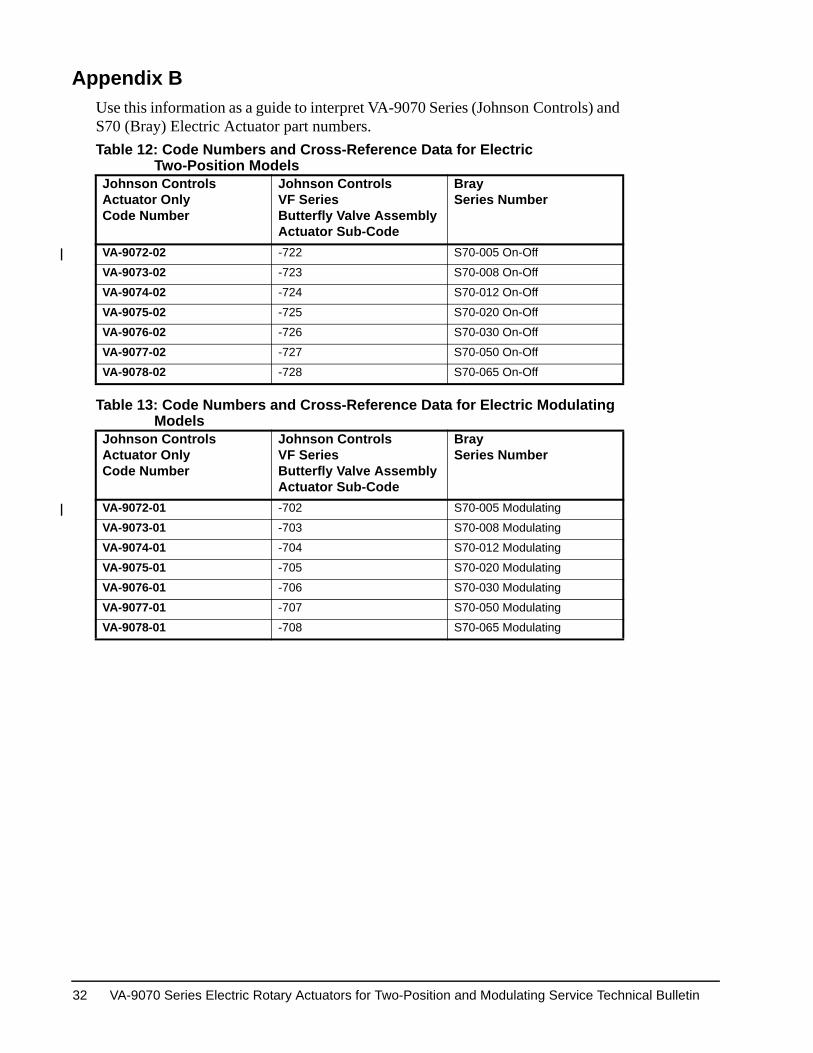
Appendix BUse this information as a guide to interpret VA-9070 Series (Johnson Controls) and S70 (Bray) Electric Actuator part numbers. Table 12: Code Numbers and Cross-Reference Data for Electric
Two-Position ModelsJohnson ControlsActuator OnlyCode Number
Johnson Controls VF SeriesButterfly Valve AssemblyActuator Sub-Code
BraySeries Number
VA-9072-02 -722 S70-005 On-Off
VA-9073-02 -723 S70-008 On-Off
VA-9074-02 -724 S70-012 On-Off
VA-9075-02 -725 S70-020 On-Off
VA-9076-02 -726 S70-030 On-Off
VA-9077-02 -727 S70-050 On-Off
VA-9078-02 -728 S70-065 On-Off
Table 13: Code Numbers and Cross-Reference Data for Electric Modulating Models
Johnson ControlsActuator OnlyCode Number
Johnson ControlsVF SeriesButterfly Valve AssemblyActuator Sub-Code
BraySeries Number
VA-9072-01 -702 S70-005 Modulating
VA-9073-01 -703 S70-008 Modulating
VA-9074-01 -704 S70-012 Modulating
VA-9075-01 -705 S70-020 Modulating
VA-9076-01 -706 S70-030 Modulating
VA-9077-01 -707 S70-050 Modulating
VA-9078-01 -708 S70-065 Modulating
VA-9070 Series Electric Rotary Actuators for Two-Position and Modulating Service Technical Bulletin 32
Table 14: Bray Part Numbering System Reference Chart BrayPart Number1, 2
Torquelb·in(N·m)
Standard Speedsin Seconds for90° Operation(Total Gear Ratio)