VAAYU- AN EFFORT TOWARDS GREENER AVIATION Institute: Indian Institute of Technology, IIT Kanpur, India Students: Mukul Atri Sriram.G Faculty Advisor : Dr. Abhijit Kushari Date of Submission : 08.05.2011
Transcript
VAAYU- AN EFFORT TOWARDS GREENER AVIATION
Institute: Indian Institute of Technology, IIT Kanpur, India
Sriram. G (4th year Undergraduate, B.Tech M.Tech Dual Degree Program, Aerospace Engineering)
Abstract :
The focus of this study is to address the critical issues related to the Propulsion system of a futuristic aircraft which would meet the ERA requirements in the N+2 time frame. The study revolves around two concepts, After Dilation and the High Bypass Geared Turbofan which are potentially capable of increasing the fuel efficiency, reducing noise emissions by a significant margin as the results indicate.
Mixed stream turbofan engines in which the core and bypass streams are mixed before expansion is now increasingly being viewed as a candidate for civil aircraft as well, besides extensive military application. The proposed concept of After Dilation is to make use of the pressure differential between the bypass and the core to mix a portion of the bypass air stream with the core flow, thus effectively mixing the flow and increasing the thrust. “After Dilation” also smoothens out the Temperature profile, thus decreasing the velocity gradient and hence the jet noise, which contributes a large part to the engine noise.
The high bypass Geared Turbofan, already in use in PW1000G shows a remarkable increase in thrust and drop in TSFC when applied to a long haul aircraft engine. Major part of the thrust is the bypass thrust due to the large mass flow rate in the bypass. Trade studies with various parameters are performed to select the design point. The trend seems to be going towards ultra high bypass ratio geared turbofans in the future. The After Dilation concept is then applied to the geared turbofan and studied.
1
INTRODUCTION:
The aircraft configuration selected for the future is the Blended Wing Body (HWB) Concept proposed by Boeing-MIT-NASA in a study ended December’10 in the report titled ‘N+3 Aircraft Concept Designs and Trade Studies, Final Report [1]. Using the BWB, the N+3 goals are to be met in the above stated report. A few changes have been made to the mainly the engine, making a futuristic after dilating, geared turbofan engine modelled using GE90-94B as the baseline engine. Our report focuses on the propulsion system of the aircraft. This propulsion system is proposed to be used on the Hybrid Wing Body
Salient features of the H-Series of aircraft as proposed in the BMN Report are discussed below [1]: • HWB configuration with lifting nose:
o Allows for supercritical outer wing profiles and improved aerodynamic performance through built-in nose-up trimming moment, via fuselage lift on nose region.
o Includes coach cabin and cargo capacity designed according to Boeing 777-200LR rules o Allows for shorter landing gear via better tail clearance o Improves propulsive efficiency via fuselage boundary layer ingestion (BLI) o Incorporates an assumed 30% reduction in structure weight, using structural weight based on
Boeing Wing MOD based response surface model (used for NASA N2A aircraft design) through use of advanced materials and manufacturing techniques
o Incorporates drooped leading edge device to increase CLmax during takeoff and approach for reduced velocities, and airframe noise, during takeoff and approach
o Uses faired undercarriage for reduced noise • Thrust vectoring, variable area nozzle:
o Allows for reduced jet noise during takeoff, optimum cruise performance, and enables operation at low fan speed.
o Provides pitch trim during cruise to minimize profile drag o Allows increase in induced drag for aircraft trim on approach using thrust vectoring combined
with elevon
Studies are done on factors that are most likely to be able to be achieved in time till 2020. Geared turbofan concept is studied as it is already in practice in the Pratt & Whitney PurePower PW1000G [2]. The efficiencies of various components are expected to increase over the span of 15 years, and the Turbine Inlet Temperature is expected to go up to 1700 K. The dilator concept is the only concept to be developed in order to make this engine a reality.
Rejection of propulsion system proposed in the Boeing-MIT-NASA Report:
The BMN report suggested aft-embedded engines with a distributed propulsion system.
This power plant proposed in the BMN report has not been chosen/studied primarily for two reasons- the complexity of airframe propulsion integration and the completion of the research, design and manufacturing of the engine.
Another major factor is that the civil aircraft industry does not experiment too much with technology unless absolutely necessary.
2
CONCEPT OF AFTER DILATION:
Mixed stream turbofan engines in which the core and bypass streams are mixed before expansion is now increasingly being viewed as a candidate for civil aircraft as well, besides extensive military application. In comparison to the separate exhaust turbofan, the major advantage of a mixed-stream concept is an improvement of about 2–3% in specific thrust and thrust specific fuel consumption (SFC).[3][4][5]
The proposed concept of After dilation is to make use of the pressure differential between the bypass and the core to mix a portion of the bypass air stream with the core flow thus effectively mixing the flow and hence increasing the thrust and smoothening out the Temperature profile, thus decreasing the velocity gradient and hence the jet noise, which contributes a huge part to the engine noise.
One of the subscale model test programs for the integrated mixer/ejector development was a joint test conducted by the NASA Lewis Research Center and Pratt & Whitney Aircraft. This test was conducted to study various mixer/ejector nozzle configurations installed on the core flow exhaust of advanced, high-bypass-ratio turbofan engines for subsonic, commercial applications.[6]
A study was conducted on GE90 engine which is used in Boeing 777, which is the baseline aircraft of our study. An Engine model was created using MATLAB. The Engine Data of GE90 is added as an appendix. Some of the performance curves of the engine are shown during both take off and cruise at an altitude of 10.668km.
Initially the GE90-94B engine on the Boeing 777-200LR has been modelled through a code in MATLAB to produce identical cruise thrust and specific fuel consumption (SFC) values in cruise.
The turbine inlet temperature comes out to be 1379. K, which is same as the TIT for GE90-94B (1380K)
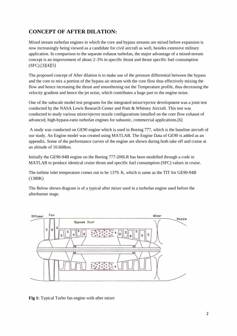
The Below shown diagram is of a typical after mixer used in a turbofan engine used before the afterburner stage.
Optimised Performance of the Existing GE90 Engine :
The below illustrated graphs give a fair estimate of the various factors affecting the performance of engine in terms of Thrust produced during cruise. The plots were generated by varying each of the factors such as OPR, Fuel flow rate, FPR, Inlet Mach No., FPR and altitude while keeping others at the cruise value. Refer Appendix to check the parameters during cruise.
Fig 2: Performance plots of GE90 Turbofan engine
4
Some observations from the above plots are:
i) Overall Pressure Ratio (OPR) always has a positive effect in increasing the available Thrust and decreasing the Specific Fuel Consumption (SFC). It is only constrained by the number of Compressor stages, their associated weight and the Turbine Inlet Temperature. The operational overall pressure ratio at cruise for GE90 engine is 40.440 and we stick with it.
ii) Increasing the fuel flow rate has a positive effect on reducing the SFC. But along with that the thrust increases and hence we have the lower most SFC values during takeoff which is around 7.910 mg/N/s. One concept which emerges is the use of a single engine during cruise while providing a low throttle setting to the other engines so that we obtain a net SFC which is lower than the case where all engines provide the same Thrust.
iii) The choice of FPR is restricted on both sides. Ideally without weight considerations a lower FPR is preferable as it increases SFC. But for an engine where bypass exit area is fixed FPR can lie in a narrow range as a very low FPR would choke the bypass nozzle and a very high FPR would choke the core nozzle.
iv) Thrust vs Inlet Mach No. Graph shows that lower the inlet mach number, higher the Thrust and hence lower the SFC. This is more so pronounced in engines of higher bypass ratio where the minimum thrust Mach Number shifts towards sonic speed and hence better are the advantages of flying slower.
v) Thrust vs Bypass Ratio graph was plotted for a constant mass flow rate and hence can be assumed for the case of engine of constant size. The advantages of having smaller turbo machinery components are evident from the plot as for a fixed fan diameter we could have Higher bypass flow area and a lower core flow area thus increasing thrust as evidenced from the plot.
vi) TSFC increases with altitude and thrust decreases as can be seen from the graph. But the advantages of flying at a higher altitude which include a reduction in drag for high speeds far outweigh the increase in SFC thus constraining the designer from tweaking with the aircraft altitude.
Fig 3: SFC vs Fan Efficiency
vii) The efficiency of the Engine is highly dependent on the polytropic efficiency of individual components. The above plot shows the high degree of variation with the fan
5
efficiency. Therefore concepts such as geared turbofan where the fan operates at a lower rpm will help a long way in reducing the SFC of the engine.
After Dilation of the Bypass flow :
The schematic diagram of the proposed engine is as shown in the figure
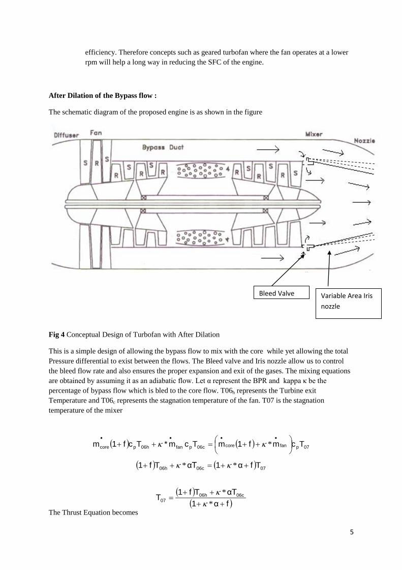
Fig 4 Conceptual Design of Turbofan with After Dilation
This is a simple design of allowing the bypass flow to mix with the core while yet allowing the total Pressure differential to exist between the flows. The Bleed valve and Iris nozzle allow us to control the bleed flow rate and also ensures the proper expansion and exit of the gases. The mixing equations are obtained by assuming it as an adiabatic flow. Let α represent the BPR and kappa κ be the percentage of bypass flow which is bled to the core flow. T06h represents the Turbine exit Temperature and T06c represents the stagnation temperature of the fan. T07 is the stagnation temperature of the mixer
The iris nozzles are variable area nozzles that have been used earlier in the fighters F-14, F-15, F-16. These nozzles provide high performance through the change of area of the exit of the nozzle. The exit is made of overlapping hydraulically adjustable flaps which can provide adjustment of area within a certain range. Some nozzles are also designed to give a variable angle of thrust. Though the thrust vectoring is not used in our engine, the variable exit area nozzle is an essential part of our engine. As the bleed ratio from the bypass to the core varies, a different area will be required to deliver high performance of the engine.[7]
A code in matlab was written for analysing the engine at different bypass bleed ratios and the results are analysed below.
For Bypass Bleed Ratio =.6
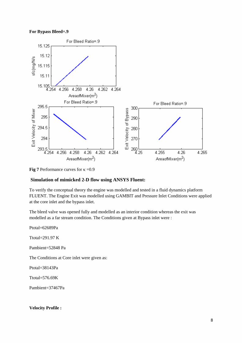
The area of the core can be varied by using an Iris nozzle nozzle. The graph shows that SFC can be reduced by decreasing the exit area thus accelerating the flow and leading to higher exit velocities. The following graphs also illustrate the reduced noise which can be seen throught the exit velocities of the mixer and the bypass exits respectively.
7
Fig 5 Performance curves for κ=.6
For Bypass bleed Ratio=0.7
Fig 6 Performance Curves for κ =.7
.7
.7 .7
8
For Bypass Bleed=.9
Fig 7 Performance curves for κ =0.9
Simulation of mimicked 2-D flow using ANSYS Fluent:
To verify the conceptual theory the engine was modelled and tested in a fluid dynamics platform FLUENT. The Engine Exit was modelled using GAMBIT and Pressure Inlet Conditions were applied at the core inlet and the bypass inlet.
The bleed valve was opened fully and modelled as an interior condition whereas the exit was modelled as a far stream condition. The Conditions given at Bypass inlet were :
Ptotal=62689Pa
Ttotal=291.97 K
Pambient=52848 Pa
The Conditions at Core inlet were given as:
Ptotal=38143Pa
Ttotal=576.69K
Pambient=37467Pa
Velocity Profile :
9
The velocity profile shows that there is sufficient mixing at the interface as shown by the blue region near the core-bypass interface. This also necessitates the optimal design of holes for efficient mixing.
Fig 8 Velocity Profile
Temperature Profile
The Temperature plots also effectively depict the contours where mixing has taken place to convert Thermal energy to Kinetic energy. The red regions depict the inlet temperature of 576.69 K which is quickly dissipated due to efficient turbulent mixing.
Fig 9 Temperature Profile
Pressure Profile :
The Pressure profile shows the propagation of pressure fronts as can be seen in both the mixed areas and the bypass region. The core region of the flow expands to be near to the ambient pressure at the exit whereas the bypass flow comes out of the nozzle in an under expanded state.
Fig 10 Pressure Profile
10
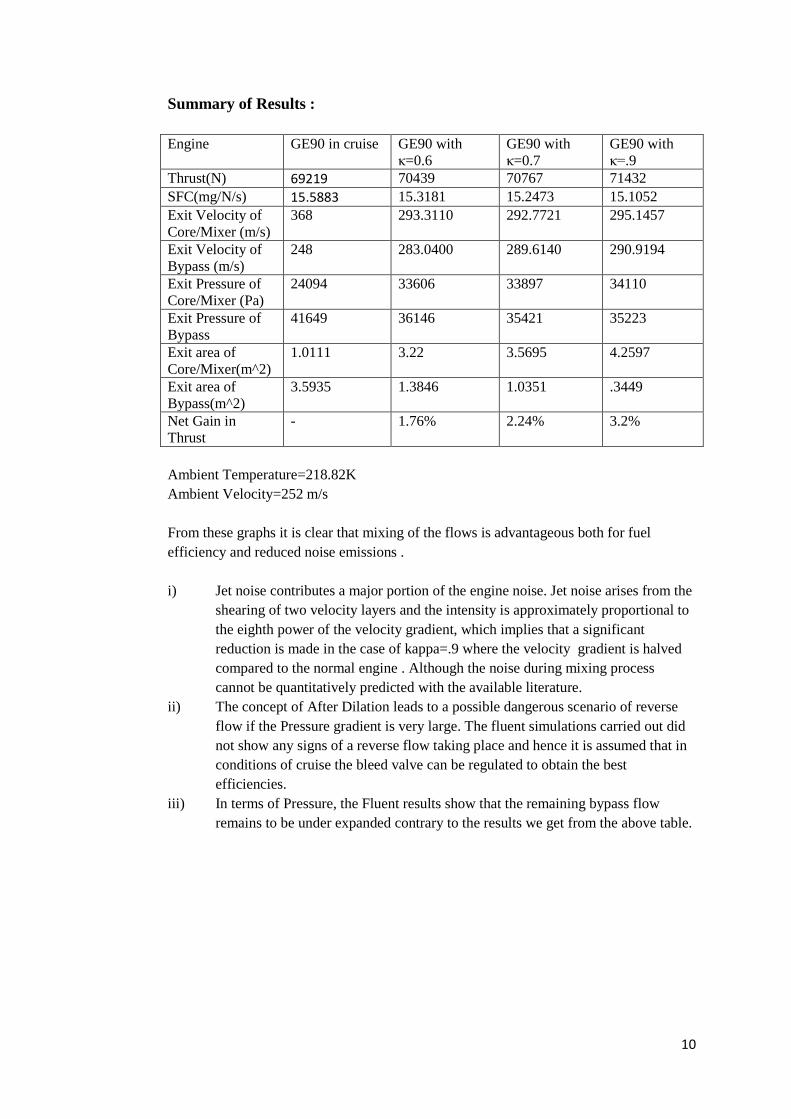
Summary of Results : Engine GE90 in cruise GE90 with
Ambient Temperature=218.82K Ambient Velocity=252 m/s From these graphs it is clear that mixing of the flows is advantageous both for fuel efficiency and reduced noise emissions . i) Jet noise contributes a major portion of the engine noise. Jet noise arises from the
shearing of two velocity layers and the intensity is approximately proportional to the eighth power of the velocity gradient, which implies that a significant reduction is made in the case of kappa=.9 where the velocity gradient is halved compared to the normal engine . Although the noise during mixing process cannot be quantitatively predicted with the available literature.
ii) The concept of After Dilation leads to a possible dangerous scenario of reverse flow if the Pressure gradient is very large. The fluent simulations carried out did not show any signs of a reverse flow taking place and hence it is assumed that in conditions of cruise the bleed valve can be regulated to obtain the best efficiencies.
iii) In terms of Pressure, the Fluent results show that the remaining bypass flow remains to be under expanded contrary to the results we get from the above table.
11
GEARED TURBOFAN:
Turbofan engines with higher bypass ratios are desired due to the increase in thrust and reduction in TSFC values. Higher bypass ratio engines lead to a higher inlet area due to which the fan diameter is increased. In order to avoid shocks and associated losses at the fan tip that reduce the engine efficiency, the fan should operate at a lower RPM. The efficiency of the LP compressors and turbines will reduce if they are also run at the same reduced RPM as the fan [8]. Else, the height of the blade of the compressor would also have to be increased to obtain optimal performance, thereby increasing the weight of the engine. Thus, it is desired that the fan is run at a reduced RPM as compared to the LPCs. Thus a planetary reduction gearbox is used. The gearbox reduces the angular velocity of the fan by the required amount and high bypass ratios can be achieved.
The fan operates at a lower Fan Pressure Ratio (FPR) as the rpm of the fan is reduced. As FPR reduces, the fan efficiency increases.
Following are benefits of the Geared Turbofan [9]:
o Low FPR and bypass exit velocity o Low fan RPM, low Fan noise and jet noise o High propulsive efficiency o Decreased length of the engine due to reduction of low-pressure spool components like LPC, LPT
and thus a reduction in engine weight o Relatively higher LPC and LPT efficiency than the normal turbofan engines
We will make use of podded engine instalments hence the Boundary Layer Ingestion Concept is not used. This will add to the drag due to the nacelle and pylon. With embedded engines, the drag coefficient for cruise is 0.0078. With podded engines, the drag coefficient goes up by 0.0015(for two engines) and the total drag coefficient, Cd becomes 0.0093. The drag corresponding to this drag coefficient comes out to be104.68kN.
12
Fig 11 Performance of Geared Turbofan Engine
Observations:
(i) In agreement with the graph for TSFC vs Overall Pressure Ratio of the GE90 engine modelled earlier, the TSFC is constantly decreasing and the Thrust is increasing. In this case, we increase our OPR to 52(for design point) to decrease TSFC and increase thrust, as the TIT constraint is stretched a bit. Currently due to material constraints, the TIT is limited to 1500K while it is projected to increase up to 1700K in the next 10-15 years. Our TIT reaches a value of 1459 K during cruise while it can go up to 2200K in maximum thrust condition for a fuel flow rate of 2.5 kg/s.
(ii) The variation of TSFC with FPR shows that for every ~1% increase in ηfan the TSFC decreases by ~ 1.16%. The efficiency of the geared turbofan is higher than the efficiency of the direct drive fan as the RPM and FPR are relatively lower. Also, we estimate that the fan efficiency will increase from 0.94(current) to 0.96(design efficiency). All our calculations are based on this reasonable assumption.
(iii) As the inlet Mach no. increases, the TSFC reduces. In fact, the TSFC curve flattens out at around 0.79-0.8 Mach. As we increase the Mach no. we obtain a reduced TSFC and the wave drag has not yet crept in. As we go along the curve, from around 0.85 onwards, the suction surface of the supercritical airfoil section of the Hybrid Wing Body will enter into the transonic region which is undesirable with regards to the fan efficiency. Thus, keeping in mind the location of the engines, the fan tip speed, fan efficiency and the inlet Mach no. vs TSFC relation, we choose M=0.83 as our design Mach no. which is also the design Mach no. of the Hybrid Wing Body.
13
(iv) The Thrust vs Inlet Mach no. shows that a better thrust is obtained at 0.83 Mach relative to 0.8 Mach at an FPR of 1.4. But, for the geared turbofan, design FPR we have chosen as 1.35. This shows us along with graph (vi) that small changes in FPR can lead to high thrust increments and improvement in SFC values.
(v) Though our fuel mass flow rate for cruise is 1.15 kg/s, we show a variation of TSFC values with the fuel flow rate. Corresponding to a fuel flow rate of 1.15 kg/s, we obtain a thrust of ~98 kN, which is almost equal to our drag. Hence, all of our thrust cruise can be provided by a single engine(FPR=1.4) at a nominal fuel flow rate of 1.15 kg/s, with a TSFC of about 11.9 mg/N/s. While the second engine is on extremely low throttle mode, the thrust produced can said to be 0. Hence, we decrease the FPR from 1.4 to 1.35 which increases our thrust to 105.6 kN and decreases the TSFC to 10.8907 mg/N/s. This means that a single engine can easily provide cruise thrust at a much reduced TSFC value(as proposed in the After-dilator concept).
At design point, the TSFC is 30.19% lower than the TSFC of GE90-94B at design point and the thrust is 52.6 % higher. SFC 10.8907 Cruise Thrust 105.6 kN SFC min. 6.1428 Max. Thrust 406.98 kN PFEI(engine alone) 3.304 kJ/kg/km
Geared Turbofan with After-dilator
Now, we use the after-dilator in the high-bypass geared turbofan engine. This leads to further lower values of TSFC and higher values of thrust. The design point changes by a small margin in this case, as the FPR is increased from 1.35(in the case of only geared turbofan) to 1.4(geared turbofan+ after dilator)
14
Fig 12 sfc vs kappa
These are the graphs for variation of SFC with area of mixer for various Bypass Bleed Ratios. The variation for SFC is seen to optimize the mixing area of the variable area nozzle. In all cases we can see that as the mixing area increases, the SFC decreases. However, the SFC attains lowest SFC values for the bleed ratio of 0.6. In other words, 60% of the bypass should be bled into the core for best performance.
Fig 13 Total Thrust vs kappa
15
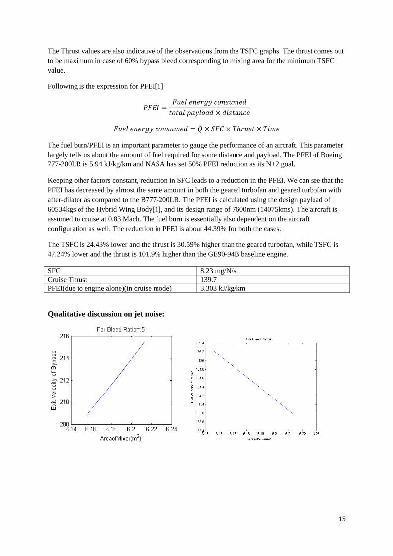
The Thrust values are also indicative of the observations from the TSFC graphs. The thrust comes out to be maximum in case of 60% bypass bleed corresponding to mixing area for the minimum TSFC value.
Following is the expression for PFEI[1]
The fuel burn/PFEI is an important parameter to gauge the performance of an aircraft. This parameter largely tells us about the amount of fuel required for some distance and payload. The PFEI of Boeing 777-200LR is 5.94 kJ/kg/km and NASA has set 50% PFEI reduction as its N+2 goal.
Keeping other factors constant, reduction in SFC leads to a reduction in the PFEI. We can see that the PFEI has decreased by almost the same amount in both the geared turbofan and geared turbofan with after-dilator as compared to the B777-200LR. The PFEI is calculated using the design payload of 60534kgs of the Hybrid Wing Body[1], and its design range of 7600nm (14075kms). The aircraft is assumed to cruise at 0.83 Mach. The fuel burn is essentially also dependent on the aircraft configuration as well. The reduction in PFEI is about 44.39% for both the cases.
The TSFC is 24.43% lower and the thrust is 30.59% higher than the geared turbofan, while TSFC is 47.24% lower and the thrust is 101.9% higher than the GE90-94B baseline engine.
Jet noise varies as the eighth power of velocity gradient[10]. In the case of GE90 engine, the core flow exit velocity and the bypass exit velocity are m/s, m/s while the aircraft is travelling at 252 m/s. On the other hand, a look at each of these pairs of bypass exit velocity and mixer exit velocity graphs, we can see that the velocity gradient is smaller than the initial case. Smaller the gradient, lower the jet noise. With this in perspective, the bleed ratio of 0.7 seems to be an optimum bleed ratio for reduction of jet noise.
17
Lean Direct Injection Combustors
LDI is included in the study, as a technology risk assessment study by NASA in the BMN report suggests that LDI is an element sure to be inducted into gas turbine engines by 2025[1]. If concentrated efforts are put into introducing this technology earlier by NASA Glenn, it will certainly be used in most engines. The Lean Direct Injector Combustor is used in this engine.
The LDI Combustors inject fuel into multiple flame zones which in turn reduces the local temperature as well as allows for lean combustion. This reduces the LTO NOx level having the same fuel burn thus helping in meeting the N+2 goals.
As per the BMN N+3 goals report, the LDI combustors reduce LTO NOx by 15-20%
Spiroid winglet
Drag consists of skin friction drag and induced drag. The induced drag is affected by parameters like Oswald’s efficiency factor(e)/span efficiency factor, aspect ratio and lift coefficient.[11] An increase in span efficiency factor reduces the induced drag. Thus, lesser thrust will be required for the same conditions. The span efficiency factor of the wing is influenced by the induced flow from the pressure surface of the wing to the suction surface. If this flow is prevented the induced drag and tip vortices can be ‘eliminated’. Few concepts such as ring wing or joined wing have been proposed to have a span efficiency of greater than 1.0, though other advantages of these configurations haven’t been observed and they lead to excessive weight. The spiroid winglets on the other hand also improve the efficiency factor and reduce the induced drag while decreasing the fuel burn by about 10% in short haul environments.[12] If these winglets work well similarly in long-haul conditions, the N+2 goals can be achieved with more ease.
Weight estimation of an engine:
Data for various engines has been taken from [13] and engines in the thrust class 250kN and above were chosen. The no. of compressor and turbine stages, fan diameter, nacelle length and thrust of the engine were given as parameters to the neural network function of MATLAB. After training the network with 20 layers of neurons, new inputs for our modified engine were given. The results gave the weight to be around 7200kgs.
This weight estimation is close to the weight estimated from data obtained from WATE.
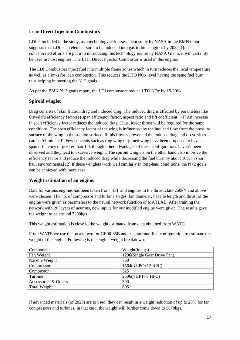
From WATE we use the breakdown for GE90-85B and use our modified configuration to estimate the weight of the engine. Following is the engine-weight breakdown:
If advanced materials (of 2020) are to used, they can result in a weight reduction of up to 20% for fan, compressors and turbines. In that case, the weight will further come down to 5878kgs.
18
Realization of no-flap wing:
In the HWB concept, it is proposed that the wings will have no flaps although. A method for implementation of this feature is suggested below.
Golf-ball Wings:
The wings of the HWB can be made of smart structures with a layer of piezoelectric material at the surface. This system is placed on both sides of the centerline of the HWB and the system is operated independently on both sides of the hybrid wing body. When actuated, the wings develop ‘dimples’ due to which the sectional aerodynamic properties change. The ratio CL/Cd, the aerodynamic efficiency increases and stall is delayed by delaying the angle at which CL,max is reached. These wings eliminate the need for flaps for higher lift coefficients. Thus, only the LE slats are required. These actuated smart structures can be used to fill the place of ailerons as well in the following manner: Whilst turning, just one side of the wing maybe in actuated state, thereby producing a difference in the CL on both sides of the wing leading to the turn.
Aft-position radial stator:
The positioning of the stator blade also plays an important role in the noise of the engine. The stator blade can be swept by an angle, called swept blade angle. If an unswept blade is to be positioned at the distance from the rotor such that the distance is equal to the distance of the tips of the rotor and a 300 swept stator blade. This upswept blade configuration with the modified blade positioning is called aft-position radial stator.[14] The noise levels can be reduced by about EPN 13dB for takeoff, 14 dB for approach and 6.5 dB for cutback, effectively reducing the noise by 33.5 EPNdB (baseline aircraft has 288EPNdB rating, thus a 11.6% reduction) using this kind of stator blade arrangement. Even though, the length of the engine and consequentially the weight of the engine are increased without decrease in thrust performance[15], the new after-dilating, geared turbofan has a very high improved thrust and very low TSFC.
Now, we take the Hybrid Wing Configuration and spiroid winglets and enhance the fuel burn of the complete aircraft both reducing the fuel burn by about 10%. Thus, the PFEI reduces to 2.675 kJ/kg/km which is a total reduction of 54.96% in the PFEI/fuel burn.
Conclusion :
The topics covered account for only improvements in propulsion systems for achieving ERA goals in the N+2 time frame. Concepts such as Lean direct Combustion Injectors , Spiroid winglets, Golf ball wings and Aft-position radial stator are futuristic concepts which hold lots of potential in reducing NOx emission, improving fuel efficiency, reducing weight and reducing noise respectively. After Dilation and High Bypass Geared turbofan, which were analysed in detail in this report hold a lot of promise in the years to come and could change the face of the aviation Industry forever.
References :
1. N+3 Aircraft Concept Designs and Trade Studies, Final Report 2. http://www.pw.utc.com/products/commercial/purepower-pw1000g.asp 3. Vivek Sanghi and B. K. Lakshmanan 2002 “Optimum Mixing of Core and Bypass
Streams in High-Bypass Civil Turbofan”, Journal of Propulsion and Power Vol 18, No.4, July-August 2002
4. Pearson, H., “Mixing of Exhaust and Bypass Flow in a Bypass Engine,” Journal of Royal Aeronautical Society, Vol. 66, Aug. 1962, pp. 528–530
5. Frost, T. H., “Practical BypassMixing Systems for Fan Jet Aero Engine,”The Aeronautical Quarterly, May 1966, pp. 141–160.
6. http://www.grc.nasa.gov/WWW/RT/RT1997/5000/5860harrington.htm 7. http://en.wikipedia.org/wiki/Propelling_nozzle#Iris_nozzles 8. http://en.wikipedia.org/wiki/Geared_turbofan 9. C. Riegler, C. Bichlmaier ‘The Geared Turbofan Technology-Opportunities, Challenges
and Readiness Status’, http:// www.mtu.de/en/technologies/engineering_news/others /Riegler_Geared_turbofan_technology.pdf
10. Philip G. Hill, Carl R. Peterson , Mechanics and Thermodynamics of Propulsion 11. Ilan Kroo ,‘Drag due to Lift: Concepts for Prediction and Reduction’, , Annu. Rev. Fluid
the.html 13. http://www.jet-engine.net/civtfspec.html 14. E. Envia, M. Nallasamy, ‘Design Selection and Analysis of a Swept and Leaned Stator
Concept’, Journal of Sound and Vibration (1999) 228(4), 793-836, Article No. jsvi.1999.2441 15. Richard P. Woodward, David M. Elliott, Christopher E. Hughes and Jeffrey J. Berton
‘Benefits of Swept-and-Leaned Stators for Fan Noise Reduction’, 16. www.stanford.edu/~cantwell/AA283.../GE90_Engine_Data.pdf