24
Sanitary Systems – made to please Vacuum Piping Guide Jets Standard

Sanitary Systems – made to please
Vacuum Piping GuideJets Standard

1 INTRODUCTION1.1 Standards and regulations1.2 Terms and Conditions1.3 Safety Annotations1.4 Support
2 SYSTEM DESCRIPTION
3 DESIGNING PIPE SYSTEM3.1 Vacuum Sewage System Layout3.1.1 Choice of piping Layout3.1.2 Location of vacuum unit in different types of buildings3.1.3 Vacuum reservoir: Calculation and build-up3.1.4 Choice of branches3.1.5 Sectioning/shut-off of pipes for service3.2 Challenges regarding different types of buildings3.2.1 Large buildings3.2.2 N/A3.2.3 N/A3.2.4 Small building3.3 Pipetables3.3.1 Table 1 - Materials3.3.2 Table 2 – Number of vacuum toilets
4 INSTALLATION GUIDELINES4.1 Vacuum System Layout4.2 Pipe connections for two Floor4.3 Horizontal Pipes4.31 Transport in horizontal pipes4.32 Transport Pocket4.33 Mounting of vacuum pipes in ceiling4.4 Pipe connections4.4.1 Joining of pipes with different dimentions4.4.2 Rodding points4.4.3 Bends4.4.4 Branches4.5 Connection to vacuum main branch4.5.1 Rising pipes from toilets4.5.2 Gooseneck4.5.3 Connection to horizontal branch pipe4.6 Toilet Connections
Table of Contents

4.6.1 Alignment of pipe to toilet valve
4.6.2 Connection to toilet valve4.6.3 Flexible hose4.6.4 Pipe clamps4.6.5 Vacuum accumulating tank4.7 Grey Water4.7.1 Grey water piping4.7.2 Grey water interface
5 TEST PROCEDURE AND ACCEPTANCE CRITERIAS5.1 Vacuum pipes only5.2 Complete vacuum system
6 DESCALING OF VACUUM SEWAGE PIPELINES

This manual is dealing with piping for vacuum sewage systems as well as waste water pipes connected to such systems. The vacuum piping must be in accordance with vacuum sewage system transportation principles:
The transport proceeds in slugs as a result of difference in pressure in front of and behind this slug.
During the transport through the piping system, the slug is affected by the gravity and will flatten out after a time. For this reason it is necessary to have low points in the piping system where the slug can form again, so that the pressure difference can be re-established.
Pipes are to be secured by clamps, and cleanouts to be made where convenient.
1.1 Standards and regulationsSee also building standards for Vacuum Toilet System:
NS EN 12109 Internal vacuum systems•
1.2 Terms and ConditionsThis manual is considered as guidelines only, and is intended to help pipeline designers to avoid common mistakes. It is not to be used as complete instructions. Pipelines are the customer’s responsibility, and Jets can not be held responsible for malfunction of the system due to incorrect pipeline design or construction.
1. Introduction
1.3 Safety Annotations
This manual is to be considered as guidelines only, and is intended to help pipeline designers avoid common mistakes. It is not to be used as complete instructions. Pipelines are the customer’s responsibility, and Jets can not be held responsible for malfunction of the system due to incorrect pipeline design or construction.
Indicates possibilities for hazards or unsafe practices, which COULD result in minor personnel injuries and/or property damage, if the required precautions are not taken.
Draws attention to specific information of technical significance which might not be obvious to specialist personnel, or points at important remarks in the procedures to follow.
1.4 SupportPlease contact Jets Standard Service.
WARNING
CAUTION
NOTE

2. System Description
A vacuum sewage system uses difference in air pressure for transport of sewage. This difference is created by the Vacuumarator. By means of pressure switches controlling start and stop of the Vacuumarator, a constant vacuum of 40%-55% (-0,40 - -0,55 bar) is maintained in the vacuum pipes.
When flushing the toilet, its contents are sucked into the piping system. Consequently transport will continue as long as the toilet valve is open. When the valve closes (after 1.5 -seconds) transport will stop. During the discharge period, the distance of transport will vary from 5 to 15 meters, depending on vacuum, dimension of pipe, direction of flow, the number of bends on pipe etc.
When transport stops, the water in the pipes will flow by gravity to the nearest low point. The pipes must consequently be installed with a water lock or “transport pocket” at this point. At the next discharging of the toilet, or other toilets connected at the same side of the “transport pocket”, the contents of the “transport pocket” will be sucked further along in the pipes. In longer lines of piping there will be a simultaneous transport from several “transport pockets” until the sewage reaches the Vacuumarator. Between each “transport pocket” the pipes should be installed with a slope along the direction of transport to secure that water will also flow in this direction.

3. Designing Pipe System
3.1 Vacuum Sewage System Layout
For installations in buildings, the choice of piping layout design will have to be adjusted to many considerations.
3.1.1 Choice of piping Layout
If possible the outlet pipe from toilets should point downwards, i.e. collecting pipes and branches should be on a lower level than the toilets.
In this way you avoid the risk of “backflow”, and sufficient vacuum for operation of toilets will always be present. Our experience has shown that in this way you obtain maximum operation reliability.
However, when using a vacuum toilet system, collecting pipes and branches may be installed in the ceiling.In this case it is vital that the piping layout is designed to avoid “backflow”, un-intended collection of water in the pipe system and securing safe transport of sewage.
NOTE
As a main rule the vacuum generating unit should always be located at the absolutely lowest point of the vacuum system. In addition it should be located in a way that main pipes and branches could be as short as possible. Branch pipes from toilets should be routed in a downward direction towards the vacuum generating unit.
3.1.2 Location of vacuum unit in different types of buildings
Usually the total volume of pipes creates the vacuum reservoir. When a toilet is flushed, 60 - 100 litres of air is let into the system. At a decrease in vacuum level, the vacuum generating unit will start and vacuum level is rebuilt.However, this takes some time (e.g. from a few seconds to several minutes, depending on pipe volume and capacity of vacuumarators). In cases of possible simultaneous flushing of many toilets ( e.g. in larger installation) the total piping volume must be big enough to make the system function. In buildings with a total pipe volume less than 160 litres, we recommend increase of vacuum reservoir by installing an accumulating tank.
3.1.3 Vacuum reservoir: Calculation and build-up

An optimally constructed piping system is designed to contain as little water as possible during ordinary operation. This is obtained by making horizontal pipes as short as possible and with as few bends as possible. Horizontal collecting pipes/main pipes should be located in a way that branches will be as short as possible.
3.1.4 Choice of branches
When deciding the number of main pipes from vacuum generating unit to branch points, the number of toilets, number of floors and the need for shutting-off for service should be considered. Each main pipe should be installed with a shut-off valve towards manifold of vacuum generating unit.
3.1.5 Sectioning/shut-off of pipes for service

3.2.3 N/A
In such building, with a high number of people in periods and a relatively low number of toilets, all the toilets will frequently be flushed simultaneously. In these cases it is vital to calculate vacuum generating capacity as well as vacuum reservoir according to simultaneous flushing of toilets. If necessary, an extra vacuum accumulating tank has to be installed to increase the vacuum reservoir.
Due to risk of low vacuum level during high load of operation, pipes from the toilets should have a downward direction, and horizontal branches should be installed lower than toilet level.
3.2.4 Small buildings
3.2 Challenges regarding different
These buildings have long corridors and consequently one may be tempted to connect many toilets to each horizontal branch of pipe. These horizontal pipes will then contain more water than what is desirable, and this will increase the risk of “backflow”. In addition, many “transport pockets”/waterlocks will reduce the level of vacuum at the end of each branch.
In certain periods public toilets will have a high frequency of flushing. This must also be considered when choosing branches.
The risk of clogging of pipes is high, and the location of rodding points is important.Shut-off valves have to be installed at branches to secure as few toilets as possible out of operation in cases of operation breaks or servicing.
3.2.1 Large buildings
3.2.2 N/A
types of buildings.

3.3 Pipetables
Material: PEH PVC Steel Stainless steel
Use: Accomodation up to 75 mm (DN 65)
Accomodation up to 75 mm (DN 65)
In engine room or other heat producing are-as. Sizes above DN 65/80 to be used*
In accomoda-tion and engine room
Minimum Pressure Rating:
PN 10 PN 10 PN 10 PN 10
3.3.1 Table 1 - Materials
PEH = High Density Polyethylene. PVC = Polyvinylchlorine, e.g. DIN 86013.
Number of vacuum toilets
Min. pipe size
ConnectionDN
PEHd x s (mm)
PVCd x s (mm)
Steeld x s (mm)
Stainless steeld x s (mm)
3 40 50 x 3.0 50 x 2.4 48.3 x 2.6 50 x 1.0
25 50 63 x 5.8 63 x 3.0 60.3 x 2.9 50 x 1.0
100 65 75 x 6.9 75 x 3.6 76.1 x 2.9** 75 x 1
3.3.2 Table 2 – Number of vacuum toilets
d = outside diameter. s = wall thickness.
* Supplier to be contacted.
** Steel pipes for more than 100 toilets; supplier to be contacted.
*** For higher number of toilets, Jets Standard to be contacted.
Plastic pipes do not resist temperatures above 60• o C under vacuum conditionsSteel pipes to be galvanized• Rules of National Authorities and Classification Societies to be followed.•
NOTE
4. Installation Guidelines
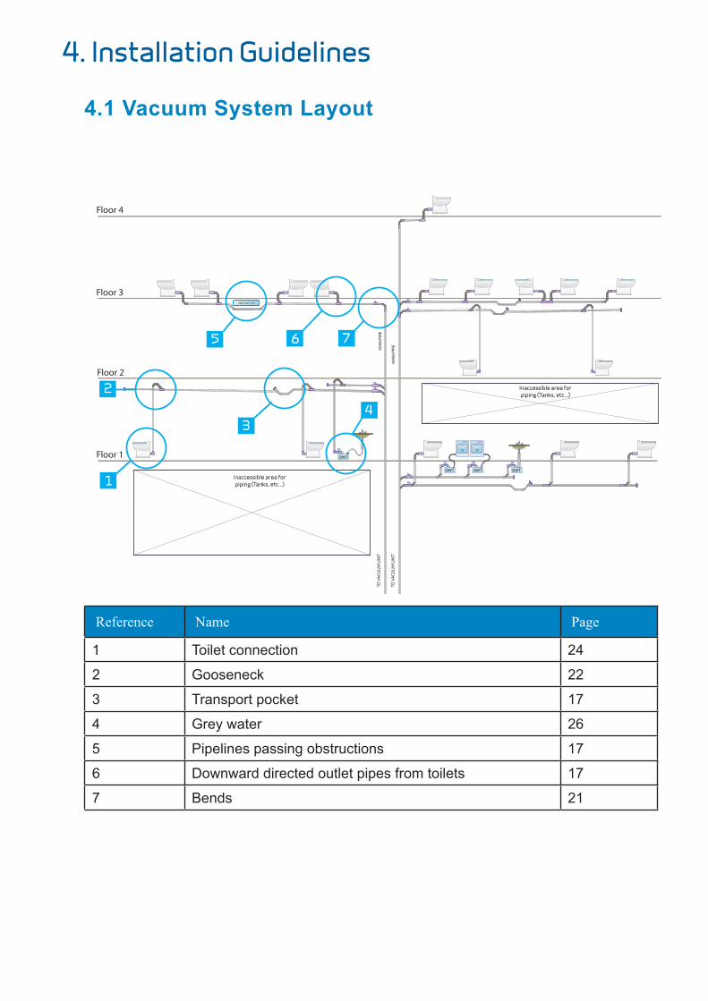
4.1 Vacuum System Layout
Reference Name Page
1 Toilet connection 24
2 Gooseneck 22
3 Transport pocket 17
4 Grey water 26
5 Pipelines passing obstructions 17
6 Downward directed outlet pipes from toilets 17
7 Bends 21
Floor 4
Floor 3
Floor 2
Floor 1

4.2 Pipe connections for two floors
4.3 Horizontal Pipes
Upward directed outlet pipes from toilet:
Vacuum pipes are preferably to be mounted with a slope between the “transport pockets” in flow direction
4.3.1 Transport in horizontal pipes
Important to remember: Total length of pipe branch • Fall•
NOTE
Floor 2
Floor 1
VENT, DUCT, ETC.Ceiling
Paneled Ceiling
Ceiling
Paneled CeilingDistance between transport pockets, see above
Ceiling
Paneled Ceiling
RoddingPoint
VENT, PIPES, ETC.
600-800mm
45<
45<0<

Downward directed outlet pipes from toilet:
The pipes may be mounted horizontally between the “transport pockets”, provided that the outlet pipes from toilets have a downward direction, or backflow is prevented.
Transport pockets” are made to re-form slugs. When a toilet on the same pipeline is flushed, the pressure difference in front of and at the back of the pocket will “push” the slug on to the next pocket.
4.3.2 Transport Pocket
When passing obstructions like crossing ventilation ducts,crossing pipes and so on, it will be advantageous to construct the passing as a “transport pocket”.
If the vacuum pipe has to be placed above such obstructions, it is important to place a “transport pocket” in front of the rising pipe. In this way maximum speed of the transported sewage is obtained in the rising pipe:
VENT, DUCT, ETC.
Deck
Ceiling
Deck
CeilingDistance between transport pockets, see above
Deck
Ceiling
RoddingPoint
VENT, PIPES, ETC.
600-800mm
45<
45<0<
VENT, DUCT, ETC.
Deck
Ceiling
Deck
CeilingDistance between transport pockets, see above
Deck
Ceiling
RoddingPoint
VENT, PIPES, ETC.
600-800mm
45<
45<0<
VENT, DUCT, ETC.Ceiling
Paneled Ceiling
Ceiling
Paneled CeilingDistance between transport pockets, see above
Ceiling
Paneled Ceiling
RoddingPoint
VENT, PIPES, ETC.
600-800mm
45<
45<0<
The distance between transport pockets should be decided considering the size of the Installation.
Recommended distances:
Building type Distance
Small building 5 meters
Medium building 10 meters
Large building 15 meters
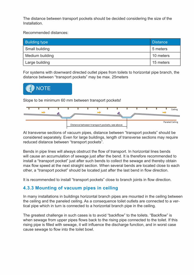
For systems with downward directed outlet pipes from toilets to horizontal pipe branch, the distance between “transport pockets” may be max. 25meters
Slope to be minimum 60 mm between transport pockets!
NOTE
At transverse sections of vacuum pipes, distance between “transport pockets” should be considered separately. Even for large buildings, length of transverse sections may require reduced distance between “transport pockets”.
Bends in pipe lines will always obstruct the flow of transport. In horizontal lines bends will cause an accumulation of sewage just after the bend. It is therefore recommended to install a “transport pocket” just after such bends to collect the sewage and thereby obtain max flow speed at the next straight section. When several bends are located close to each other, a “transport pocket” should be located just after the last bend in flow direction.
It is recommended to install “transport pockets” close to branch joints in flow direction.
In many installations in buildings horizontal branch pipes are mounted in the ceiling between the ceiling and the paneled ceiling. As a consequence toilet outlets are connected to a ver-tical pipe which in turn is connected to a horizontal branch pipe in the ceiling.
The greatest challenge in such cases is to avoid “backflow” to the toilets. “Backflow” is when sewage from upper pipes flows back to the rising pipe connected to the toilet. If this rising pipe is filled with sewage, it will influence the discharge function, and in worst case cause sewage to flow into the toilet bowl.
4.3.3 Mounting of vacuum pipes in ceiling
VENT, DUCT, ETC.Ceiling
Paneled Ceiling
Ceiling
Paneled CeilingDistance between transport pockets, see above
Ceiling
Paneled Ceiling
RoddingPoint
VENT, PIPES, ETC.
600-800mm
45<
45<0<

Horizontal branch pipes between ceiling and the paneled ceiling are to be placed as close to the paneled ceiling as possible, i.e. “transport pockets” to form lower boundary layer towards the ceiling.
In this way maximum space for gooseneck in the joint between rising pipe from toilet to horizontal pipe is obtained.
4.3.3.1 Mounting of horizontal branch pipes in the paneled ceiling
4.4 Pipe connections
The number of toilets connected to branches and collecting pipes will decide the pipe di-mension. The most commonly used dimension for pipes from toilets, and also from branch-es is DN50 for a number of toilets up to 20- 25 toilets. For collecting pipes with larger quantity of toilets than this, DN 65 is used.
4.4.1 Joining of pipes with different dimensions
Rising pipes with vacuum transport from lower to higher levels must never be installed with transition to larger dimension of pipe! Correct way to this, see illustration under.
CAUTION
The reason for this is that larger dimension of pipe creates less speed of air and consequently slower transport and shorter distances of transport. The consequences of this are increased risk of build-up of sewage and thereby “backflow”.
45
BRANCH PIPE
BRANCH PIPE
BRANCH PIPE
BRANCH PIPE
MA
IN P
IPE
45
45
45
45
45
1.5 X d(min)
R=3 X d(min)
VENT, DUCT, ETC.Ceiling
Paneled Ceiling
Ceiling
Paneled CeilingDistance between transport pockets, see above
Ceiling
Paneled Ceiling
RoddingPoint
VENT, PIPES, ETC.
600-800mm
45<
45<0<

Rodding points should be installed with suitable distances and sufficient access. In longer stretches of pipes one should install the rodding points in connection with “transport pockets”.
4.4.2 Rodding points
Connection of horizontal branches to downward going collecting pipes shall always be done with a downward 45º connection. In larger systems we recommend shut-off valve for each branch. Remember to make sufficient access for shut-off valves.
45
BRANCH PIPE
BRANCH PIPE
BRANCH PIPE
BRANCH PIPE
MA
IN P
IPE
45
45
45
45
45
1.5 X d(min)
R=3 X d(min)
45
BRANCH PIPE
BRANCH PIPE
BRANCH PIPE
BRANCH PIPEM
AIN
PIP
E
45
45
45
45
45
1.5 X d(min)
R=3 X d(min)

Bends to be made with a large radius of curvature.
4.4.3 Bends
For plastic pipes, and steel “push-fit” pipes minimum radius to be 2 x D, or a 90o bend made of two 45o bend pieces.
For welded steel pipes, minimum bend radius to be 3 x D
Inside of pipes and fittings to be smooth and without obstructions to avoid clogging.
Connecting of pipes to be made at maximum angle of 45º in direction of transport. T-pipes are not to be used. Branch pipes are always to be connected to horizontal main pipes from above. Branch pipes always to be connected to vertical main pipes at an angle of 45º
4.4.4 Branches
45
BRANCH PIPE
BRANCH PIPE
BRANCH PIPE
BRANCH PIPE
MA
IN P
IPE
45
45
45
45
45
1.5 X d(min)
R=3 X d(min)
45
BRANCH PIPE
BRANCH PIPE
BRANCH PIPE
BRANCH PIPE
MA
IN P
IPE
45
45
45
45
45
1.5 X d(min)
R=3 X d(min)
45
BRANCH PIPE
BRANCH PIPE
BRANCH PIPE
BRANCH PIPE
MA
IN P
IPE
45
45
45
45
45
1.5 X d(min)
R=3 X d(min)
45
BRANCH PIPE
BRANCH PIPE
BRANCH PIPE
BRANCH PIPE
MA
IN P
IPE
45
45
45
45
45
1.5 X d(min)
R=3 X d(min)

4.5 Connection to vacuum main branch
Vertical pipes connections are to be straight running with no bends, to obtain the best pos-sible transport out from the toilet.
The diameter of the rising pipe must not be increased in the rising part.
Max. length of horizontal branch is not to exceed 30 m.
4.5.1 Rising pipes from toilets
RoddingPoint
Max 30 m
Max 30 m
Max
300
0 m
m
MA
IN P
IPE
If horizontal outlet pipe from a toilet, a “transport pocket” must be installed in front of verti-cal rising pipe.
The rising pipe is to be connected to the up-per side of the horizontal branch pipe with a gooseneck and at an angle of 45° in the direction of flow.
4.5.2 Gooseneck
NOTE
Max 1500mm

4.5.3 Connection to horizontal branch pipe
The rising pipe from a toilet must never be connected to a point on a horizontal branch pipe that may be filled with water, i.e. at a low level point of the pipe line.
The reason for this is that in case of low vacuum in horizontal branch pipes, water may be sucked through the gooseneck and gradually the rising pipe will be filled with sewage.
In corridors where rising pipes from toilets on both sides are connected to a common branch pipe, the rising pipe should go as high up as possible and then point downwards towards the branch pipe.
CAUTION
CORRIDOR
Paneled ceiling
ceiling
Bathroom Bathroom

4.6 Toilet Connections
To avoid leakage between the toilet valve and the toilet bowl, it is important that the pipe is properly aligned.
4.6.1 Alignment of pipe to toilet valve
4.6.2 Connection to toilet valveRubber sleeve and elbow to be secured by hose clamps.
4.6.3 Flexible hoseFor the purpose of using less pipe fittings • and secure easier maintenance, we rec-ommend to connect the toilet to the pipe system by means of a flexible hose.This flexible hose must not be longer than • 1 m. The distance between toilet outlet and the • pipe system must not exceed 70% of the totale length of the hose.The flexible hose is to be secured by hose • clamps.
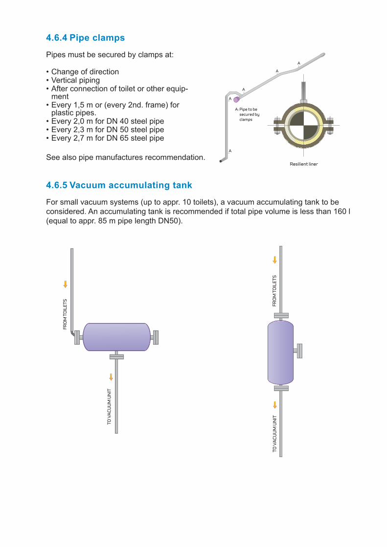
Pipes must be secured by clamps at:
Change of direction • Vertical piping • After connection of toilet or other equip-• ment Every 1,5 m or (every 2nd. frame) for • plastic pipes. Every 2,0 m for DN 40 steel pipe • Every 2,3 m for DN 50 steel pipe • Every 2,7 m for DN 65 steel pipe•
4.6.4 Pipe clamps
For small vacuum systems (up to appr. 10 toilets), a vacuum accumulating tank to be considered. An accumulating tank is recommended if total pipe volume is less than 160 l (equal to appr. 85 m pipe length DN50).
4.6.5 Vacuum accumulating tank
TO V
ACU
UM
UN
IT
FRO
M T
OIL
ETS
FRO
M T
OIL
ETS
TO V
ACU
UM
UN
IT
TO V
ACU
UM
UN
IT
FRO
M T
OIL
ETS
FRO
M T
OIL
ETS
TO V
ACU
UM
UN
IT
See also pipe manufactures recommendation.
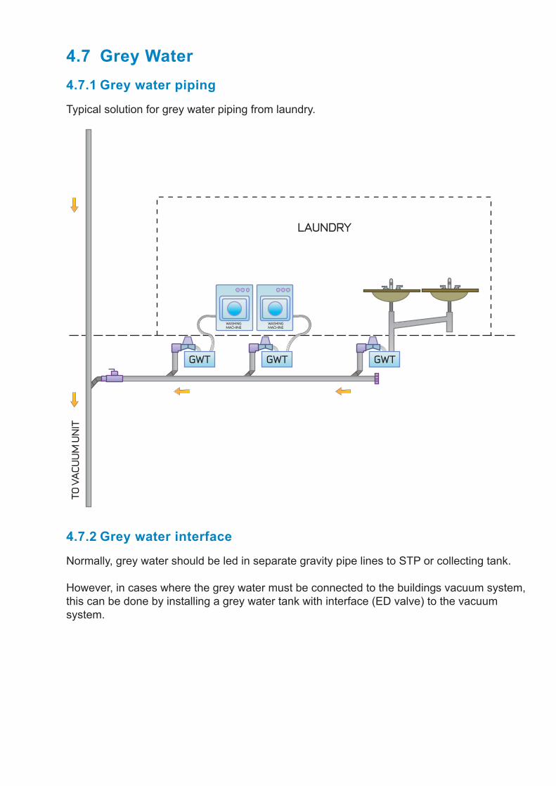
4.7 Grey Water
Typical solution for grey water piping from laundry.
4.7.1 Grey water piping
GWTGWTGWT
LAUNDRY
TO V
ACU
UM
UN
IT
WASHINGMACHINE
WASHINGMACHINE
Normally, grey water should be led in separate gravity pipe lines to STP or collecting tank.
However, in cases where the grey water must be connected to the buildings vacuum system, this can be done by installing a grey water tank with interface (ED valve) to the vacuum system.
4.7.2 Grey water interface

5. Acceptance Criterias
5.1 Vacuum pipes onlyLeakage test of complete vacuum pipes, without any components - toilets, grey water interface tanks, vacuumarators etc.- connected.
All pipe ends to be blinded.
Maximum accepted leakage: Vacuum drop from -0,6 bar to -0,5 bar during one hour.
5.2 Complete vacuum systemLeakage test of complete vacuum system, with all components- toilets, grey water interface tanks, vacuumarators etc.- connected.
Maximum accepted leakage: Vacuum drop from -0,55 bar to -0,4 bar during 20 minutes.

Urine scale is a hard substance that arises of a chemical reaction between the calcium in the water and the urine. Without any action taken there will be a build-up of scale in the vacuum pipes sooner or later depending on various factors. The temperature, the contents of calcium in the fresh water and the frequency of the use of the toilets are factors which decide the rapidity of the scale build-up.
In order to avoid scale build-up, it is recommended to follow the Jets descaling pro-grammes.
The Jets descaling programmes give treatment for 4 different scenarios:
6. Descaling of Vacuum Sewage Pipelines
The Jets descaling maintenance programme offers treatment to clean pipes in order to avoid new scale build-up.The Jets descaling programme offers treatment to minor scale build-up and is done over a longer period of time.The Jets descaling boosting programme offers treatment to severe scale build-up where immediate action is necessary.Strong acid treatment is recommended to extremely severe scale build-up. This requires that the toilets must be disconnected and the pipes plugged.
Fill up the pipe line with a liquid mixture of phosphoric acid and water. 10% acid and 90% waterArrange circulation of the mixture if possible. Keep the circulation running for 24 hoursFlush out with water.If there are still remains of urine scale, use the same procedure (a-c) with a mixture of 10% of Tetra Pyro-Potassium Phosphate.
The Jets descaling programmes allow running toilets during the processes 1-3.It is therefore not necessary to disconnect the toilets or plug the pipes during the descaling process.
Jets recommend 2 options:Manual dozing: Poor the Jets descaling liquid directly into the toilets according to recommended dosing programme by Jets.Automatical dozing: Dosing units to be installed in the vessel according to the Jets recommendation.
It is highly recommended to follow the Jets recommendations accurately in order to obtain maximum effect.
Please contact Jets to get a dosing programme adapted to your installation.
1
2
3
4
1
2
a
b
cd


