ITER Vacuum Vessel Supports Cadarache, 21 August – 7 September 2007 Andrea Capriccioli 22/08/2007 11.45 pag. 1 of 9 Vacuum Vessel Support – ongoing activity report n°1 New Electromagnetic Forces (22 August 2007) During the downward disruptions the max load per vertical support should be close to 40 MN (Ioki; Wang; Capriccioli meeting on 23th of August): this value includes the dead weight and the electromagnetic horizontal forces contribution. On the basis of this total value (40 MN) it is roughly possible to estimate the electromagnetic vertical force: for the downward disruptions the application point of the net horizontal force (73 MN) is not clear but if an application point 3 m upper the vertical supports it’s presumed and 90° rotated (with respect to the vertical peak position), we obtain a vertical contribution of about 6.5 MN. This means that the component due to the vertical loads only results 40-6.5 = 33.5 MN. If the same vertical amplification factor (1.1) and the peak factor (2) are applied, we obtain as first approximation a Total vertical force (Tvf) equal to 176 MN (⇒ 90/9 + Tvf/9 *1.1 + 2 = 33.5 MN). Downward Plasma Disruption With reference to the Neoprene material characteristics, it’s possible to consider the following values: Neoprene transient compression limit = 80 MPa (Ref. K. Ioki) = average static pressure = 20 MPa = max static pressure ≤ 40 MPa If φ=960 mm (Ref. X.Wang) is the external bearing pad diameter, the average pressure of 80 MPa on neoprene is reached (net φ=800mm: the average pressure results = Max local 80 MPa during transient with =1 safety factor). In this case we have no safety margin but other possibilities can be analyzed: VDE Downward Forces Vertical [MN) Horizontal [MN] 176* (from 72; ratio of ≈ 2.4) (* to be checked) 73 (from 25; ratio of 3) Asymmetry peak= 2 MN Application point=3 m* (* to be defined) Dynamic ampl.fact.= 1.1 Dynamic ampl.fact.=1.7
Transcript
ITER Vacuum Vessel Supports Cadarache, 21 August – 7 September 2007
Andrea Capriccioli 22/08/2007 11.45 pag. 1 of 9
Vacuum Vessel Support – ongoing activity report n°1 New Electromagnetic Forces (22 August 2007) During the downward disruptions the max load per vertical support should be close to 40 MN
(Ioki; Wang; Capriccioli meeting on 23th of August): this value includes the dead weight and the
electromagnetic horizontal forces contribution.
On the basis of this total value (40 MN) it is roughly possible to estimate the electromagnetic
vertical force: for the downward disruptions the application point of the net horizontal force (73
MN) is not clear but if an application point 3 m upper the vertical supports it’s presumed and 90°
rotated (with respect to the vertical peak position), we obtain a vertical contribution of about 6.5
MN. This means that the component due to the vertical loads only results 40-6.5 = 33.5 MN.
If the same vertical amplification factor (1.1) and the peak factor (2) are applied, we obtain as first
approximation a Total vertical force (Tvf) equal to 176 MN (⇒ 90/9 + Tvf/9 *1.1 + 2 = 33.5 MN).
Downward Plasma Disruption With reference to the Neoprene material characteristics, it’s possible to consider the following values: Neoprene transient compression limit = 80 MPa (Ref. K. Ioki) = average static pressure = 20 MPa = max static pressure ≤ 40 MPa If φ=960 mm (Ref. X.Wang) is the external bearing pad diameter, the average pressure of 80 MPa
on neoprene is reached (net φ=800mm: the average pressure results = Max local 80 MPa during
transient with =1 safety factor).
In this case we have no safety margin but other possibilities can be analyzed:
VDE Downward Forces Vertical [MN) Horizontal [MN]
176* (from 72; ratio of ≈ 2.4) (* to be checked)
73 (from 25; ratio of 3)
Asymmetry peak= 2 MN Application point=3 m* (* to be defined)
Dynamic ampl.fact.= 1.1 Dynamic ampl.fact.=1.7
Andrea Capriccioli 22/08/2007 11.45 pag. 2 of 9
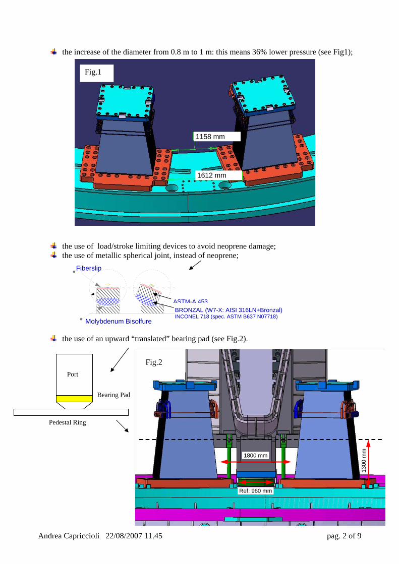
the increase of the diameter from 0.8 m to 1 m: this means 36% lower pressure (see Fig1);
the use of load/stroke limiting devices to avoid neoprene damage; the use of metallic spherical joint, instead of neoprene;
the use of an upward “translated” bearing pad (see Fig.2).
While in the toroidal direction seems feasible to increase the bearing pad size from 960 up to 1700 or more (Fig.2), in the radial direction (Fig.3) the maximum neoprene diameter should be around 1200 mm. In every case, changing the neoprene diameter from 800 to 1200 mm induces an area increment of about 2.3 times and an average pressure less then 35 MPa (against the previous 80 MPa).
1158 mm
max 1400 mm
1200 mm
Fig.3
Andrea Capriccioli 22/08/2007 11.45 pag. 4 of 9
Other open points:
• Bearing pad dimensions: lower ring (two small models show roughly the level of
stress in an example of ring). The sketch of the axial section is shown in Fig.4 and
the dimensions are set only for a preliminary analysis (see “Mageba Pot
Bearing Pad outer ring (half section): sketch and brief ANSYS analysis 2D analysis (ring with inner fillet 10 mm radius): Stresses in [MPa]; Displacements in [mm]