Page 1
VALLIAMMAI ENGINEERING COLLEGE
SRM Nagar, Kattankulathur – 603 203
DEPARTMENT OF CIVIL ENGINEERING
QUESTION BANK
V SEMESTER
CE 6501 – STRUCTURAL ANALYSIS I
Regulation – 2013
Academic Year 2017 – 18
Prepared by
Mr. T.R.Banu Chander, Assistant Professor/CIVIL
Mr. S. Karthick, Assistant Professor/CIVIL
Ms. G. Geetha, Assistant Professor/ CIVIL
Page 2
VALLIAMMAI ENGINEERING COLLEGE
SRM Nagar, Kattankulathur – 603 203
DEPARTMENT OF CIVIL ENGINEERING
QUESTION BANK
SUBJECT : CE 6501 STRUCTURAL ANALYSIS I
SEM / YEAR: V/III
UNIT I -INDETERMINATE FRAMES
Degree of static and kinematic indeterminacies for plane frames- Analysis of indeterminate pin-jointed
frames- Rigid frames (Degree of statical indeterminacy up to two) - Rigid frames (Degree of static
indeterminacy up to two) - Energy and consistent deformation methods.
PART A
Q.N
o Questions BT
Level
Competence
1. Define compatibility condition. BT-1 Remembering
2. What is mean by degree of indeterminacy? BT-1 Remembering
3. State the equilibrium condition. BT-1 Remembering
4. List out the types of frames and explain in details. BT-1 Remembering
5. Write the difference between static and kinematic indeterminacy of
structure.
BT-1 Remembering
6. Name any four methods used for computation of deflection in
structure.
BT-1 Remembering
7. Differentiate static equilibrium and dynamic equilibrium. BT-2 Understanding
8. Distinguish between determinate and indeterminate structures. BT-2 Understanding
9. Discuss about external indeterminacy and internal indeterminacy of
structure.
BT-2 Understanding
10. Describe in details about redundant force. BT-2 Understanding
Page 3
11. Calculate degree of indeterminacy of propped cantilever beam. BT-3 Applying
12. To find out the degree of indeterminacy of structures as given below. BT-3 Applying
13. Define strain energy. BT-3 Applying
14. Explain in detail about consistent deformation method. BT-4 Analyzing
15. What do you understand by the concept of portal frame? BT-4 Analyzing
16. Explain the equation for degree of indeterminacy of 2D trusses. BT-4 Analyzing
17. What is meant by perfect frame? BT-5 Evaluating
18. Determine the free end slope of a cantilever due to applied moment,
M at free end using energy principle.
BT-5 Evaluating
19. Differentiate pin-jointed frames and rigid frames. BT-6 Creating
20. Draw the detailed diagrams of plane frames and space frames. BT-6 Creating
PART B
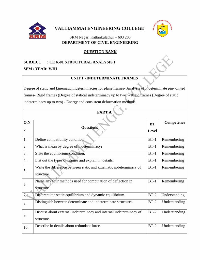
1. Identify the forces in the members of the truss shown in figure. The
cross sectional area of vertical and horizontal members is 4000 mm2
and that of the diagonals is 6000mm2.
BT-1 Remembering
2. Analyze the truss shown in figure by consistent deformation
method. Assume that the cross-sectional areas of all members are
same.
BT-1 Remembering
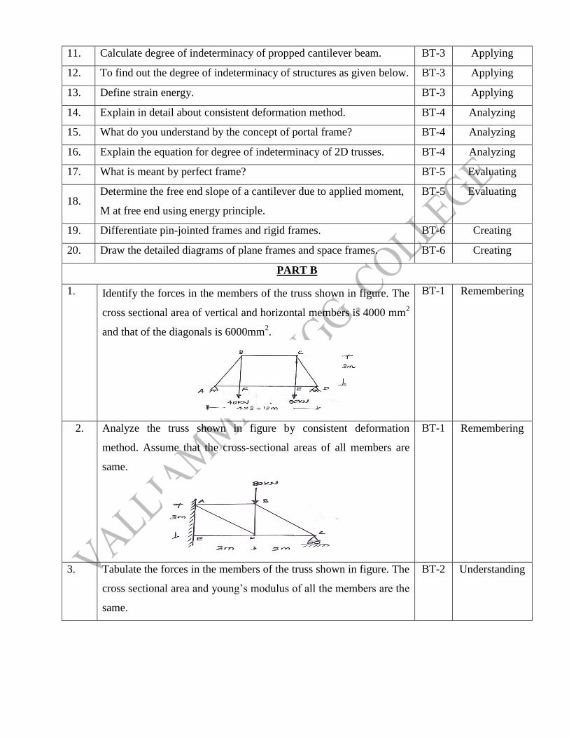
3. Tabulate the forces in the members of the truss shown in figure. The
cross sectional area and young‟s modulus of all the members are the
same.
BT-2 Understanding
Page 4
4. Three wires AO, BO and CO support a load of 40KN as shown in
figure. The cross sectional areas of all the wires are the same.
Determine the forces in all the wires.
BT-2 Understanding
5. Estimate the reaction components as is shown in figure.
i) Propped cantilever beam
ii) Overhanging beam
BT-3 Applying
6. The frame ABCDEF shown in figure has a regular hexagon shape
and is subjected to 60KN vertical downward loads at A and D. All
the members are of the same material and have the same cross-
sectional area. Determine the forces in all members.
BT-3 Applying
Page 5
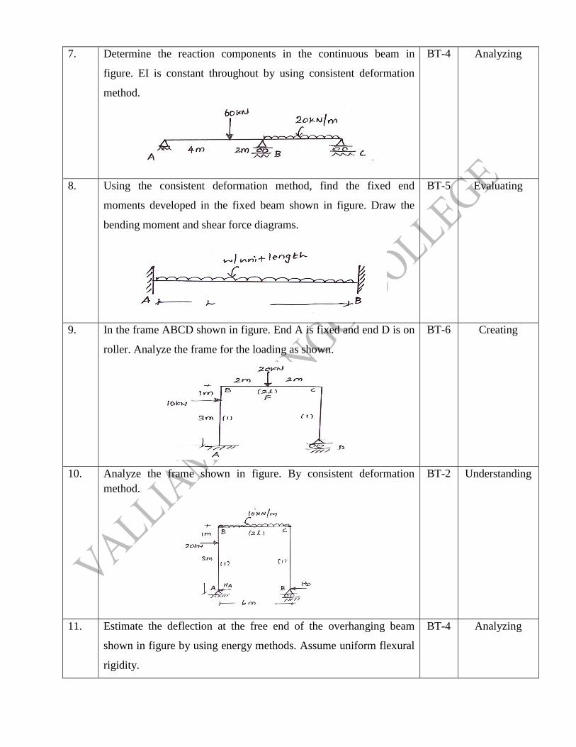
7. Determine the reaction components in the continuous beam in
figure. EI is constant throughout by using consistent deformation
method.
BT-4 Analyzing
8. Using the consistent deformation method, find the fixed end
moments developed in the fixed beam shown in figure. Draw the
bending moment and shear force diagrams.
BT-5 Evaluating
9. In the frame ABCD shown in figure. End A is fixed and end D is on
roller. Analyze the frame for the loading as shown.
BT-6 Creating
10. Analyze the frame shown in figure. By consistent deformation
method.
BT-2 Understanding
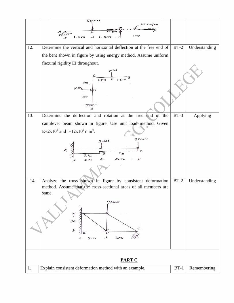
11. Estimate the deflection at the free end of the overhanging beam
shown in figure by using energy methods. Assume uniform flexural
rigidity.
BT-4 Analyzing
Page 6
12. Determine the vertical and horizontal deflection at the free end of
the bent shown in figure by using energy method. Assume uniform
flexural rigidity EI throughout.
BT-2 Understanding
13. Determine the deflection and rotation at the free end of the
cantilever beam shown in figure. Use unit load method. Given
E=2x10⁵ and I=12x10
6 mm
4.
BT-3 Applying
14. Analyze the truss shown in figure by consistent deformation
method. Assume that the cross-sectional areas of all members are
same.
BT-2 Understanding
PART C
1. Explain consistent deformation method with an example. BT-1 Remembering
Page 7
2. Write the degree of indeterminancy for the indeterminate structure BT-1 Remembering
3. Explain the
(i) Plane frame
(ii)Pin jointed Frame
(iii)Rigid frame
BT-6 Creating
4. Find the slope and deflections of a cantilever beam with point load at
free end using energy methods
BT-3 Applying
UNIT II- MOVING LOADS AND INFLUENCE LINES
Influence lines for reactions in statically determinate structures- influence lines for members forces in
pin-jointed frames- Influence lines for shear force and bending moment in beam sections- Calculation
of critical stress resultants due to concentrated and distributed moving loads- Muller Breslau‟s
principle – Influence lines for continuous beams and single storey rigid frames- Indirect model
analysis for influence lines of indeterminate structures – Beggs deformeter.
PART A
Q.No Questions
BT
Level Competence
1. State importance of ILD? BT-1 Remembering
2. Define muller Breslau”s principle? BT-1 Remembering
3. What are the types of connections possible in the model of
beg”deformeter?
BT-1 Remembering
4. Enumerate the influence line diagram. BT-1 Remembering
5.
When a series of wheel loads move along a girder, what is the
condition for getting maximum bending moment under any one
point load?
BT-1 Remembering
6. What is begg”s deforester? BT-1 Remembering
7. Explain similitude. BT-2 Understanding
8. Illustrate the principle of dimensional similarity. BT-2 Understanding
9. Where do you have the absolute maximum bending moment in a
simply supported beam when a series of wheel loads cross it?
BT-2 Understanding
10. Name the type of rolling load for which the absolute maximum BT-2 Understanding
Page 8
bending moment occurs at the mid span of a beam.
11. Differentiate rolling load and static load. BT-3 Applying
12. Write the absolute maximum bending moment due to a moving
UDL longer than the span of a simply supported beam.
BT-3 Applying
13. Write the three types of connections possible with the model used
with begg”sdeformeter.
BT-3 Applying
14. What do you understand by an influence line for bending moment? BT-4 Analyzing
15. Explain Maxwell-betti”s theorem. BT-4 Analyzing
16. What is meant by maximum shear force diagram? BT-4 Analyzing
17. Select the location of maximum shear force in a simple beam with
any kind of loading
BT-5 Evaluating
18. Sketch a qualitative influence line diagrams for the support reactions
of a simply supported beam of span L.
BT-5 Evaluating
19. Draw the influence line diagram. BT-6 Creating
20. Draw influence lines for support reactions in a simply supported
beam?
BT-6 Creating
PART B
1. A system of four loads 80, 160, 160 and 120 kN crosses a simply
supported beam of span 25m with the 120 kN load leading. The
loads are equally spaced at 1m. Determine the values of the
following using influence lines.
1. Maximum bending moment at a section 10m from left support
2. Absolute maximum shear force and bending moment in the beam.
BT-1 Remembering
2. A beam has a span of 24m, draw the influence line diagram for the
bending moment and shear force at a section 8m from the left and
also determine maximum bending moment and shear force at this
section due to two point loads of 10kN and 6kN at a fixed distance
of 2m apart rolling from left to right with 6kN load leading.
BT-1 Remembering
3. Two point loads of 100kN and 200kN spaced 3m apart cross a girder
of span 12 meters from left to right with the 100kN leading.
1. Draw the ILD for shear force and bending moment and find
the values of maximum bending moment
BT-1 Remembering
Page 9
2. Find the values of maximum shear force and bending
moment at a section 4m from the left hand support.
3. Evaluate the absolute maximum bending moment due to the
given loading system.
4. A simply supported beam has a span of 16m, is subjected to a UDL
(dead load) of 5kN/m and a UDL (live load) of 8kN/m (longer than
the span) travelling from left to right.
1. Draw the ILD for shear force and bending moment at a
section 4m from left end.
2. Use these diagrams to determine the maximum shear force
and
bending moment at this section.
BT-2 Understanding
5. The following system of wheel load crosses a span 30m.
Wheel load: 16 16 20 30
Distance between centers: 3 3 5 5
1. To find the maximum value of BM
2. Shear force in the span.
BT-3 Applying
6. Determine the influence line diagram for bending moment at a point
D, the middle point of span AB of a continuous beam ABC of span
AB=6m and BC=4m simply supported at supports A,B and C.
Compute the ordinates at every 1m interval.
BT-4 Analyzing
7. The warren girder of 25m span is made of 5 panels of 5m each. The
diagonals are inclined at 60° to the horizontal. Draw the influence
line diagram for force in upper chord member in the second panel
from left. Hence evaluate the forces in it when there is load of 60 kN
at each lower joint.
BT-5 Evaluating
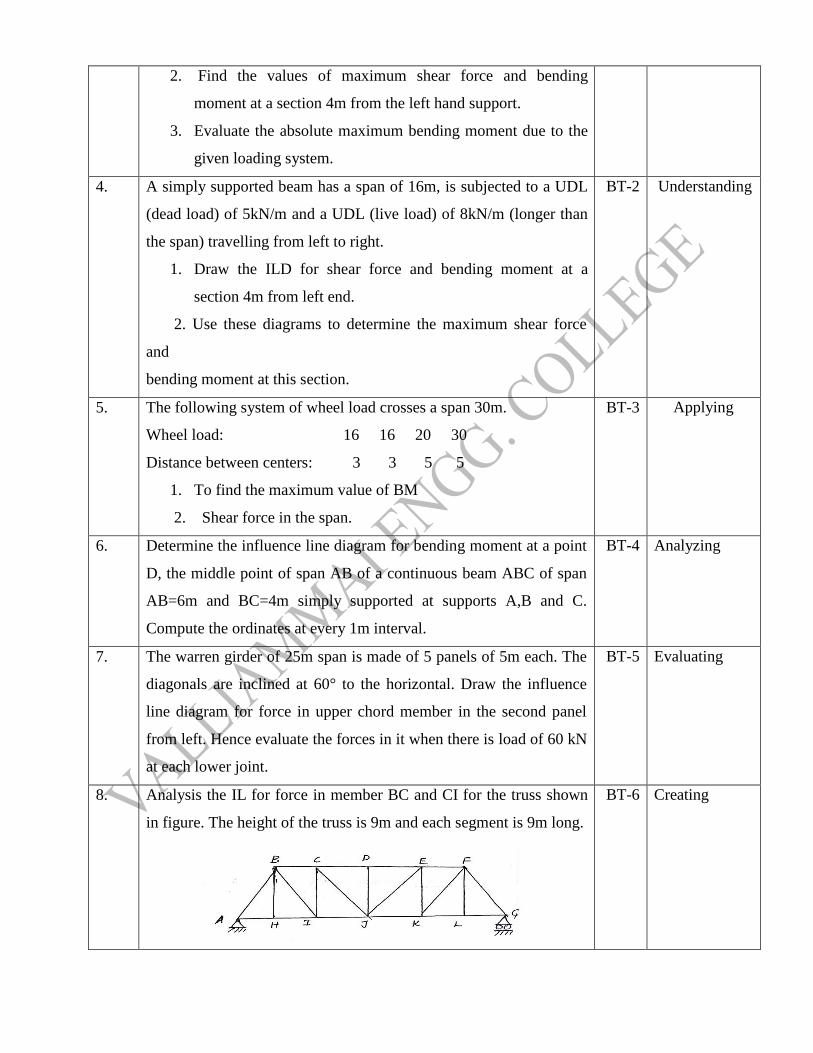
8. Analysis the IL for force in member BC and CI for the truss shown
in figure. The height of the truss is 9m and each segment is 9m long.
BT-6 Creating
Page 10
9. Draw the influence line diagram for the propped reaction of a
propped cantilever beam having span 6m. EI=Constant.
BT-6 Creating
10. Draw the influence line for MB for the continuous beam ABC simply
supported at A and C using Muller Breslau`s principle. AB=3m,
BC=4m.EI is constant.
BT-5 Evaluating
11. Draw the influence line for RA for the continuous beam ABC of
span AB = BC = 4m Simply supported at A, B &C. Compute the
ordinates at every 1m interval, EI= constant.
BT-2 Understanding
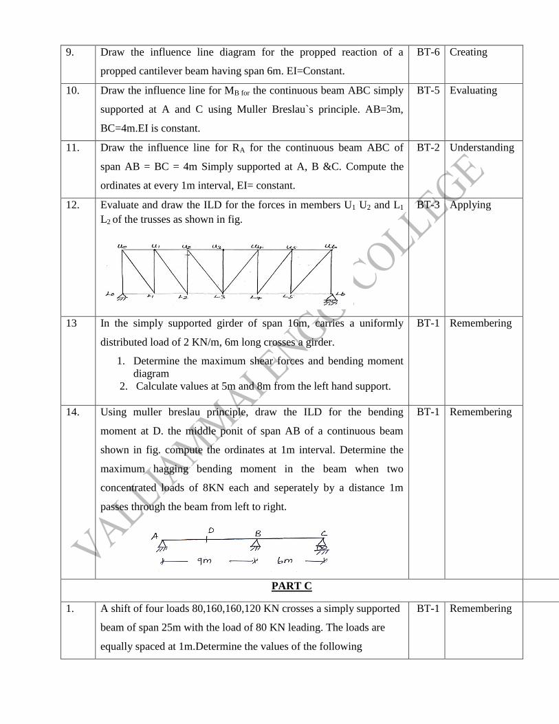
12. Evaluate and draw the ILD for the forces in members U1 U2 and L1
L2 of the trusses as shown in fig.
BT-3 Applying
13 In the simply supported girder of span 16m, carries a uniformly
distributed load of 2 KN/m, 6m long crosses a girder.
1. Determine the maximum shear forces and bending moment
diagram
2. Calculate values at 5m and 8m from the left hand support.
BT-1 Remembering
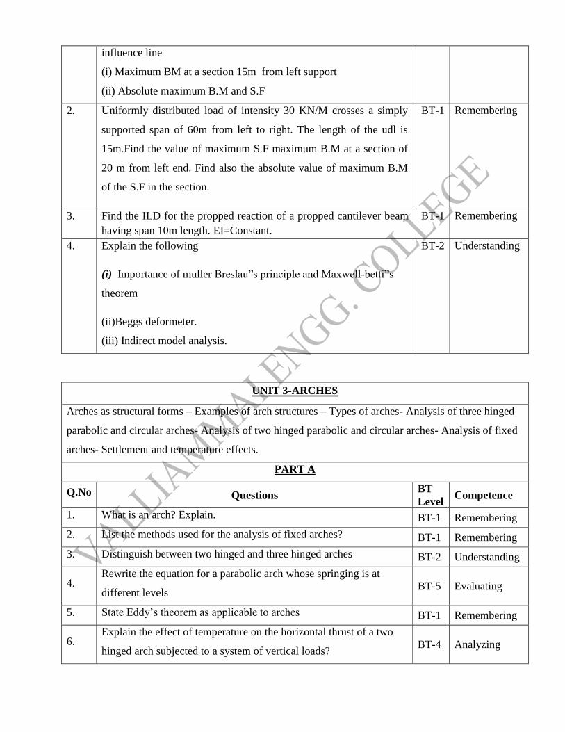
14. Using muller breslau principle, draw the ILD for the bending
moment at D. the middle ponit of span AB of a continuous beam
shown in fig. compute the ordinates at 1m interval. Determine the
maximum hagging bending moment in the beam when two
concentrated loads of 8KN each and seperately by a distance 1m
passes through the beam from left to right.
BT-1 Remembering
PART C Remembering
1. A shift of four loads 80,160,160,120 KN crosses a simply supported
beam of span 25m with the load of 80 KN leading. The loads are
equally spaced at 1m.Determine the values of the following
BT-1 Remembering
Page 11
influence line
(i) Maximum BM at a section 15m from left support
(ii) Absolute maximum B.M and S.F
2. Uniformly distributed load of intensity 30 KN/M crosses a simply
supported span of 60m from left to right. The length of the udl is
15m.Find the value of maximum S.F maximum B.M at a section of
20 m from left end. Find also the absolute value of maximum B.M
of the S.F in the section.
BT-1 Remembering
3. Find the ILD for the propped reaction of a propped cantilever beam
having span 10m length. EI=Constant.
BT-1 Remembering
4. Explain the following
(i) Importance of muller Breslau”s principle and Maxwell-betti”s
theorem
(ii)Beggs deformeter.
(iii) Indirect model analysis.
BT-2 Understanding
UNIT 3-ARCHES
Arches as structural forms – Examples of arch structures – Types of arches- Analysis of three hinged
parabolic and circular arches- Analysis of two hinged parabolic and circular arches- Analysis of fixed
arches- Settlement and temperature effects.
PART A
Q.No Questions BT
Level Competence
1. What is an arch? Explain. BT-1 Remembering
2. List the methods used for the analysis of fixed arches? BT-1 Remembering
3. Distinguish between two hinged and three hinged arches BT-2 Understanding
4. Rewrite the equation for a parabolic arch whose springing is at
different levels BT-5 Evaluating
5. State Eddy‟s theorem as applicable to arches BT-1 Remembering
6. Explain the effect of temperature on the horizontal thrust of a two
hinged arch subjected to a system of vertical loads? BT-4 Analyzing
Page 12
7. Show the positions of a moving point load for maximum negative
and positive Bending moments in a three hinged arch. BT-3 Applying
8. Rewrite the expressions for radial shear and normal thrust in a three
hinged parabolic arch? BT-5 Evaluating
9. Define radial shear and normal thrust. BT-1 Understanding
10. Mention the examples where arch action is usually encountered BT-1 Understanding
11. Define a linear arch BT-1 Remembering
12. Discuss the degree of static indeterminacy of a three hinged
parabolic arch BT-2 Understanding
13. Illustrate under what conditions will the bending moment in an arch
be zero throughout BT-3 Applying
14. Compare the two hinged and three hinged arches BT-6 Creating
15. Explain how will you calculate the slope of the arch at any point in a
parabolic arch with two hinges? BT-4 Analyzing
16. Explain how you will calculate the horizontal thrust in a two hinged
parabolic arch if there is a rise in temperature. BT-4 Analyzing
17. Classify the arches according to their shapes BT-2 Understanding
18. Discuss the types of arches according to their support conditions BT-2 Understanding
19. Draw the influence line for radial shear at a section of a three hinged
arch BT-3 Applying
20. Write the formula to calculate the change in rise in three hinged arch
if there is a rise in temperature. BT-6 Creating
PART B
1.
A circular three hinged arch of span 25m with a central rise of 5m is
hinged at the crown and the end supports. It carries a point load of
100kN at 6m from the left support. Examine and Calculate
i. The reaction at the supports (8 Marks)
ii. Moment at 5m from the left support (8 Marks)
BT-1 Remembering
2.
A three hinged circular arch of span 16m and rise 4m is subjected to
two point loads of 100 kN and 80 kN at the left and right quarter
span points respectively. Examine and find the reaction at the
supports. Find also the bending moment, radial shear and normal
BT-1 Remembering
Page 13
thrust at 6m from left support.
3.
A symmetrical three hinged arch has a span of 50 & rise 5m. Find
and examine the maximum bending moment at a quarter point of the
arch caused by a uniformly distributed load of 10kN/m which
occupies any portion of the span. Indicate the position of the load
for this condition.
BT-1 Remembering
4.
A three hinged parabolic arch of span 30m and rise 5m carries a
uniformly distributed load of 40kN per meter on the whole span and
a point load of 200kN at a distance of 5m from the right end. Find
and examine the horizontal thrust, resultant reaction, bending
moment and normal thrust at a section 5m from the left end.
BT-2 Understanding
5.
A three hinged parabolic arch has supports at different levels having
span 20m and carries a UDL of 30kN/m over the left half of the
span. The left support is 5m below the crown and the right support
is 4m below the crown. Draw the BMD. Also analyze and find the
normal thrust and radial shear at a section 4m from the left support.
BT-4 Analyzing
6.
A parabolic two hinged arch has a span of 40m and a rise of 5m. A
concentrated load 10kN acts at 15m from the left support. The
second moment of area varies as the secant of the inclination of the
arch axis. Calculate the horizontal thrust and reactions at the hinge.
Also calculate maximum bending moment at the section.
BT-3 Applying
7.
Evaluate the horizontal thrust in a two hinged parabolic arch of span
10m and rise 25m carrying an UDL of 24 kN/m over the left half
span, assuming secant variation of its sectional moment of area.
Also calculate the Bending Moment at the crown and draw the
BMD.
BT-5 Evaluating
8.
Analyse and derive the expression for horizontal thrust in a two
hinged parabolic arch carrying a point load P at a distance one
fourth span from left support .Assume I=Io Secθ.
BT-4 Analyzing
9.
A two hinged parabolic arch of span L and rise h carries a triangular
load covering a distance a from the left end,the intensity varying
uniformly from zero to W. Discuss and obtain an expression for the
BT-2 Understanding
Page 14
horizontal thrust.
10. Formulate the expression for horizontal thrust in a two hinged semi-
circular arch of radius R, carrying a point load W at the crown. BT-6 Creating
11.
A symmetrical three-hinged circular arch has a span of 13m and a
rise to the central hinge of 3m. It carries a vertical load of 15kN at
3m from the left hand end. Analyze and find
i) The reactions at the support (4 marks)
ii) Magnitude of the thrust at the springings (4 marks)
iii) Bending moment at 5m from the left hand hinge (4
marks)
The max. positive and negative bending moment (4 marks)
BT-4 Analyzing
12.
A two hinged parabolic arch of span 25m and rise 5m carries an udl
of 38kN/m covering a distance of 10m from the left end. Calculate
the
i) Horizontal thrust (5 marks)
ii) The reactions at the hinges (5 marks)
iii) Maximum negative moment (6 marks)
BT-3 Applying
13.
A three hinged parabolic arch of 30m span and 6m central rise
carries a point load of 8kN at a distance of 10m horizontally from
the left hinge. Calculate the normal thrust, shear force at the section.
Also calculate and discuss the maximum positive and negative
bending moment.
BT-2 Understanding
14.
A three hinged parabolic arch is of span 48m and central rise 10m.
It carries audlof 0.75 t/m over the left hand half of span. Calculate
the reactions at the end. Also estimate and find the values of the
normal thrust, shear force and bending moment at 6m, 12m and 30m
from left hinge.
BT-1 Remembering
PART C
1. Explain the different types of arches with neat sketch BT-1 Remembering
2.
(i)Is three hinged arch is statically determinate or not?Why?
(ii)Settlement and temperature effect on arches
(iii)Difference between three hinged and two hinged parabolic
BT-1 Remembering
Page 15
arches
3.
Calculate and discuss the maximum positive and negative bending
moment for a three hinged parabolic arch of 3m span and 6m central
rise carries a point load of 17kN at a distance of 20m horizontally
from the left hinge. Calculate the normal thrust, shear force at the
section.
BT-2 Understanding
4. Derive the expression for horizontal thrust in a two hinged parabolic
arch carrying point load W. Assume I=Io Secθ. BT-2 Understanding
UNIT 4- SLOPE DEFLECTION METHOD
Continuous beams- Rigid frames (with sway)- Rigid frames (without sway)- Symmetry and anti-
symmetry- Simplification for hinged end- Support displacements.
PART A
Q.N
o Questions BT
Level Competence
1. Write down the equilibrium equations used in slope deflection method BT-3 Applying
2. Describe the basic assumption made in slope deflection method? BT-2 Understanding
3. Calculate the fixed end moment for the fixed beam of span „L‟ and
carrying a point load „W‟ at the centre.
BT-3 Applying
4. What is the moment at a hinged end of a simple beam? BT-1 Remembering
5. Write down the slope deflection equation for fixed end support BT-6 Creating
6. Write the general equations for finding out the moment in a beam AB
by using slope deflection equation?
BT-6 Creating
7. What are the quantities in terms of which the unknown moments are
expressed in slope deflection method? Illustrate it.
BT-3 Applying
8. Explain the distribution factor BT-4 Analyzing
9. Say true or false and if false, Justify your answer “slope deflection
method is a force method”?
BT-1 Remembering
10. Explain the reasons for sway in portal frames. BT-4 Analyzing
11. What are the sign conventions used in slope deflection method? BT-1 Remembering
Page 16
12. Why slope-deflection method is called a displacement method? BT-1 Remembering
13. State and evaluate the limitations of slope deflection method BT-5 Evaluating
14. Mention and evaluate any three reasons due to which sway may occur
in portal frames
BT-5 Evaluating
15. Who introduced slope-deflection method of analysis? BT-1 Remembering
16. Write the fixed end moments for a beam carrying a central clockwise
moment.
BT-1 Remembering
17. What is the basis on which the sway equation is formed for a
structure? Explain.
BT-2 Understanding
18. Discuss the slope-deflection equations available for each span. BT-2 Understanding
19. What is the moment at a hinged end of a simple beam? BT-2 Understanding
20. Explain degree of freedom. BT-4 Analyzing
PART B
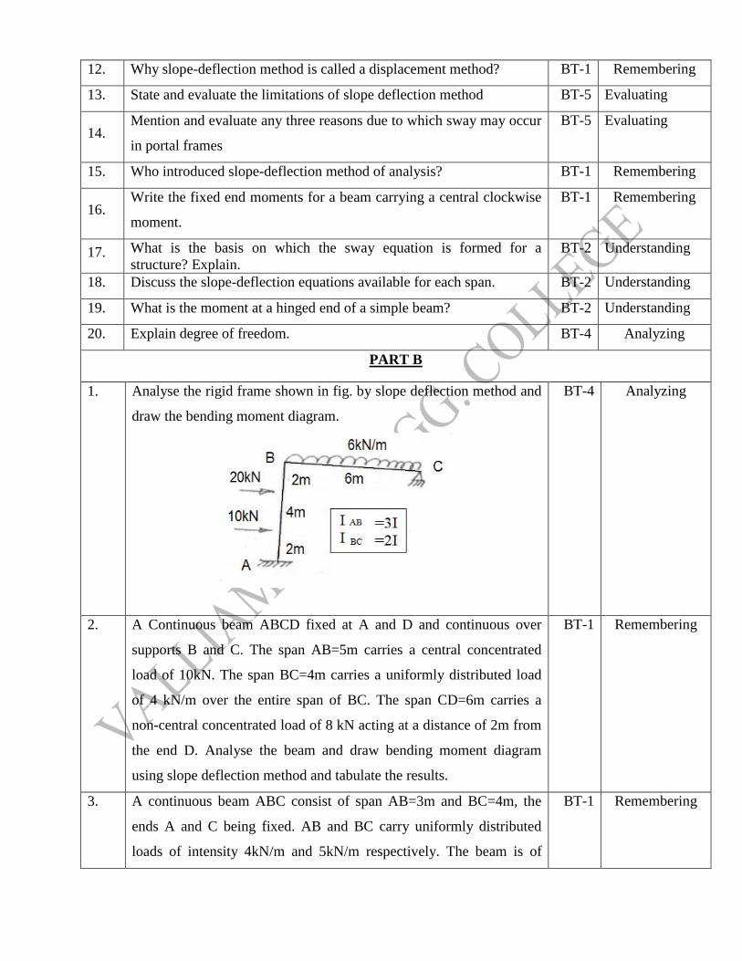
1. Analyse the rigid frame shown in fig. by slope deflection method and
draw the bending moment diagram.
BT-4 Analyzing
2. A Continuous beam ABCD fixed at A and D and continuous over
supports B and C. The span AB=5m carries a central concentrated
load of 10kN. The span BC=4m carries a uniformly distributed load
of 4 kN/m over the entire span of BC. The span CD=6m carries a
non-central concentrated load of 8 kN acting at a distance of 2m from
the end D. Analyse the beam and draw bending moment diagram
using slope deflection method and tabulate the results.
BT-1 Remembering
3. A continuous beam ABC consist of span AB=3m and BC=4m, the
ends A and C being fixed. AB and BC carry uniformly distributed
loads of intensity 4kN/m and 5kN/m respectively. The beam is of
BT-1 Remembering
Page 17
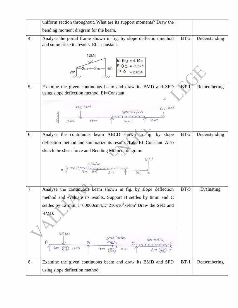
uniform section throughout. What are its support moments? Draw the
bending moment diagram for the beam.
4. Analyse the portal frame shown in fig. by slope deflection method
and summarize its results. EI = constant.
BT-2 Understanding
5. Examine the given continuous beam and draw its BMD and SFD
using slope deflection method. EI=Constant.
BT-1 Remembering
6. Analyse the continuous beam ABCD shown in fig. by slope
deflection method and summarize its results .Take EI=Constant. Also
sketch the shear force and Bending Moment diagram.
BT-2 Understanding
7. Analyse the continuous beam shown in fig. by slope deflection
method and evaluate its results. Support B settles by 8mm and C
settles by 12 mm. I=60000cm4,E=210x106kN/m
2.Draw the SFD and
BMD.
BT-5 Evaluating
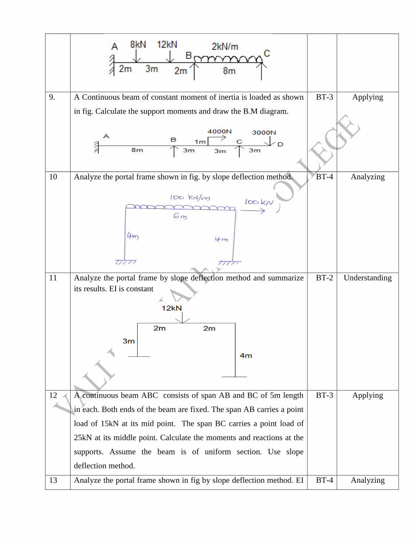
8. Examine the given continuous beam and draw its BMD and SFD
using slope deflection method.
BT-1 Remembering
Page 18
9. A Continuous beam of constant moment of inertia is loaded as shown
in fig. Calculate the support moments and draw the B.M diagram.
BT-3 Applying
10 Analyze the portal frame shown in fig. by slope deflection method.
BT-4 Analyzing
11 Analyze the portal frame by slope deflection method and summarize
its results. EI is constant
BT-2 Understanding
12 A continuous beam ABC consists of span AB and BC of 5m length
in each. Both ends of the beam are fixed. The span AB carries a point
load of 15kN at its mid point. The span BC carries a point load of
25kN at its middle point. Calculate the moments and reactions at the
supports. Assume the beam is of uniform section. Use slope
deflection method.
BT-3 Applying
13 Analyze the portal frame shown in fig by slope deflection method. EI BT-4 Analyzing
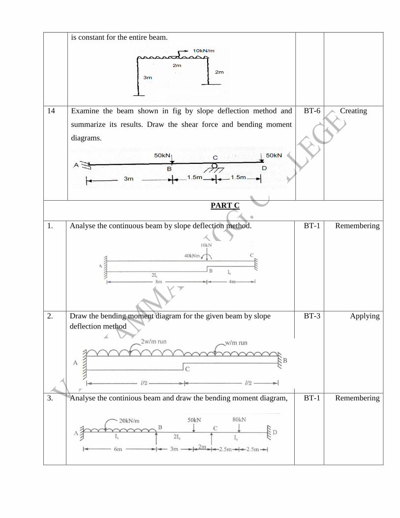
Page 19
is constant for the entire beam.
14 Examine the beam shown in fig by slope deflection method and
summarize its results. Draw the shear force and bending moment
diagrams.
BT-6 Creating
PART C
1. Analyse the continuous beam by slope deflection method.
BT-1 Remembering
2. Draw the bending moment diagram for the given beam by slope
deflection method
BT-3 Applying
3. Analyse the continious beam and draw the bending moment diagram,
BT-1 Remembering
Page 20
4 A continuous beam ABC consist of span AB=4m and BC=5m, the
ends A and C being fixed. AB and BC carry uniformly distributed
loads of intensity 5kN/m and 7kN/m respectively. The beam is of
uniform section throughout. What are its support moments? Draw the
bending moment diagram for the beam.
BT-5 Evaluating
UNIT V MOMENT DISTRIBUTION METHOD
Distribution and carryover of moments- Stiffness and carry over factors- Analysis of continuous
beams- Plane rigid frames without sway- Plane rigid frames with sway Naylor‟s simplification.
PART A
Q.No Questions BT
Level Competence
1. Define Stiffness? BT-1 Remembering
2. State how the redundancy of a rigid frame is calculated? BT-1 Remembering
3. Explain carry over factor and distribution factor? BT-6 Creating
4. What is carry-over moment? BT-1 Remembering
5.
Give the relative stiffness when the far end is
(a) Simply supported and
(b) Fixed.
BT-1 Remembering
6. What is sway corrections? BT-2 Understanding
7. What are the advantages of Continuous beam over simply supported
beam?
BT-2 Understanding
8. How is the moment induced at a fixed end calculated when a moment M
is applied at the end of prismatic beam without translation?
BT-3 Applying
9. What is the difference between absolute and relative stiffness? BT-4 Analyzing
10. What are the advantages of continuous beams over simply supported
beams?
BT-5 Evaluating
11. Explain the concepts involved in the Moment distribution method (Hardy
Cross method).
BT-2 Understanding
12. Define: Distribution factor BT-1 Remembering
Page 21
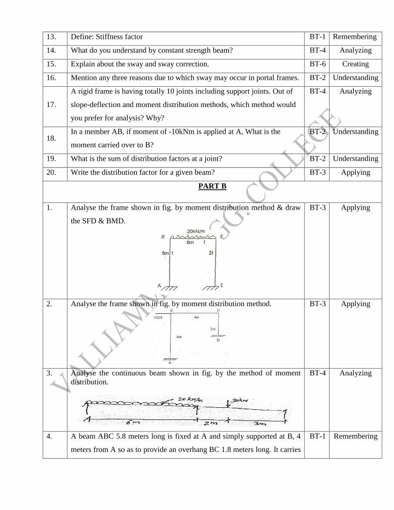
13. Define: Stiffness factor BT-1 Remembering
14. What do you understand by constant strength beam? BT-4 Analyzing
15. Explain about the sway and sway correction. BT-6 Creating
16. Mention any three reasons due to which sway may occur in portal frames. BT-2 Understanding
17.
A rigid frame is having totally 10 joints including support joints. Out of
slope-deflection and moment distribution methods, which method would
you prefer for analysis? Why?
BT-4 Analyzing
18. In a member AB, if moment of -10kNm is applied at A, What is the
moment carried over to B?
BT-2 Understanding
19. What is the sum of distribution factors at a joint? BT-2 Understanding
20. Write the distribution factor for a given beam? BT-3 Applying
PART B
1. Analyse the frame shown in fig. by moment distribution method & draw
the SFD & BMD.
BT-3 Applying
2. Analyse the frame shown in fig. by moment distribution method.
BT-3 Applying
3. Analyse the continuous beam shown in fig. by the method of moment
distribution.
BT-4 Analyzing
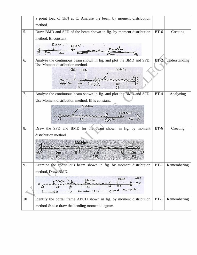
4. A beam ABC 5.8 meters long is fixed at A and simply supported at B, 4
meters from A so as to provide an overhang BC 1.8 meters long. It carries
BT-1 Remembering
Page 22
a point load of 5kN at C. Analyse the beam by moment distribution
method.
5. Draw BMD and SFD of the beam shown in fig. by moment distribution
method. EI constant.
BT-6 Creating
6. Analyse the continuous beam shown in fig. and plot the BMD and SFD.
Use Moment distribution method.
BT-2 Understanding
7. Analyse the continuous beam shown in fig. and plot the BMD and SFD.
Use Moment distribution method. EI is constant.
BT-4 Analyzing
8. Draw the SFD and BMD for the beam shown in fig. by moment
distribution method.
BT-6 Creating
9. Examine the continuous beam shown in fig. by moment distribution
method. Draw BMD.
BT-1 Remembering
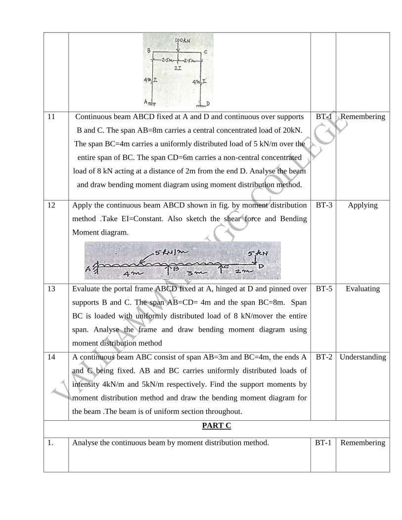
10 Identify the portal frame ABCD shown in fig. by moment distribution
method & also draw the bending moment diagram.
BT-1 Remembering
Page 23
11 Continuous beam ABCD fixed at A and D and continuous over supports
B and C. The span AB=8m carries a central concentrated load of 20kN.
The span BC=4m carries a uniformly distributed load of 5 kN/m over the
entire span of BC. The span CD=6m carries a non-central concentrated
load of 8 kN acting at a distance of 2m from the end D. Analyse the beam
and draw bending moment diagram using moment distribution method.
BT-1 Remembering
12 Apply the continuous beam ABCD shown in fig. by moment distribution
method .Take EI=Constant. Also sketch the shear force and Bending
Moment diagram.
BT-3 Applying
13 Evaluate the portal frame ABCD fixed at A, hinged at D and pinned over
supports B and C. The span AB=CD= 4m and the span BC=8m. Span
BC is loaded with uniformly distributed load of 8 kN/mover the entire
span. Analyse the frame and draw bending moment diagram using
moment distribution method
BT-5 Evaluating
14 A continuous beam ABC consist of span AB=3m and BC=4m, the ends A
and C being fixed. AB and BC carries uniformly distributed loads of
intensity 4kN/m and 5kN/m respectively. Find the support moments by
moment distribution method and draw the bending moment diagram for
the beam .The beam is of uniform section throughout.
BT-2 Understanding
PART C
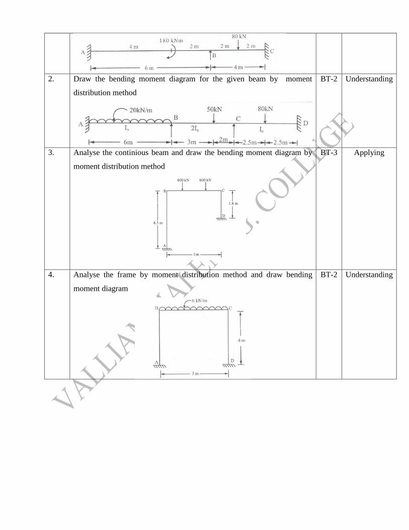
1. Analyse the continuous beam by moment distribution method.
BT-1 Remembering
Page 24
2. Draw the bending moment diagram for the given beam by moment
distribution method
BT-2 Understanding
3. Analyse the continious beam and draw the bending moment diagram by
moment distribution method
BT-3 Applying
4. Analyse the frame by moment distribution method and draw bending
moment diagram
BT-2 Understanding
Page 25
G.GEETHA KARTHICK S T.R. BANU CHANDER
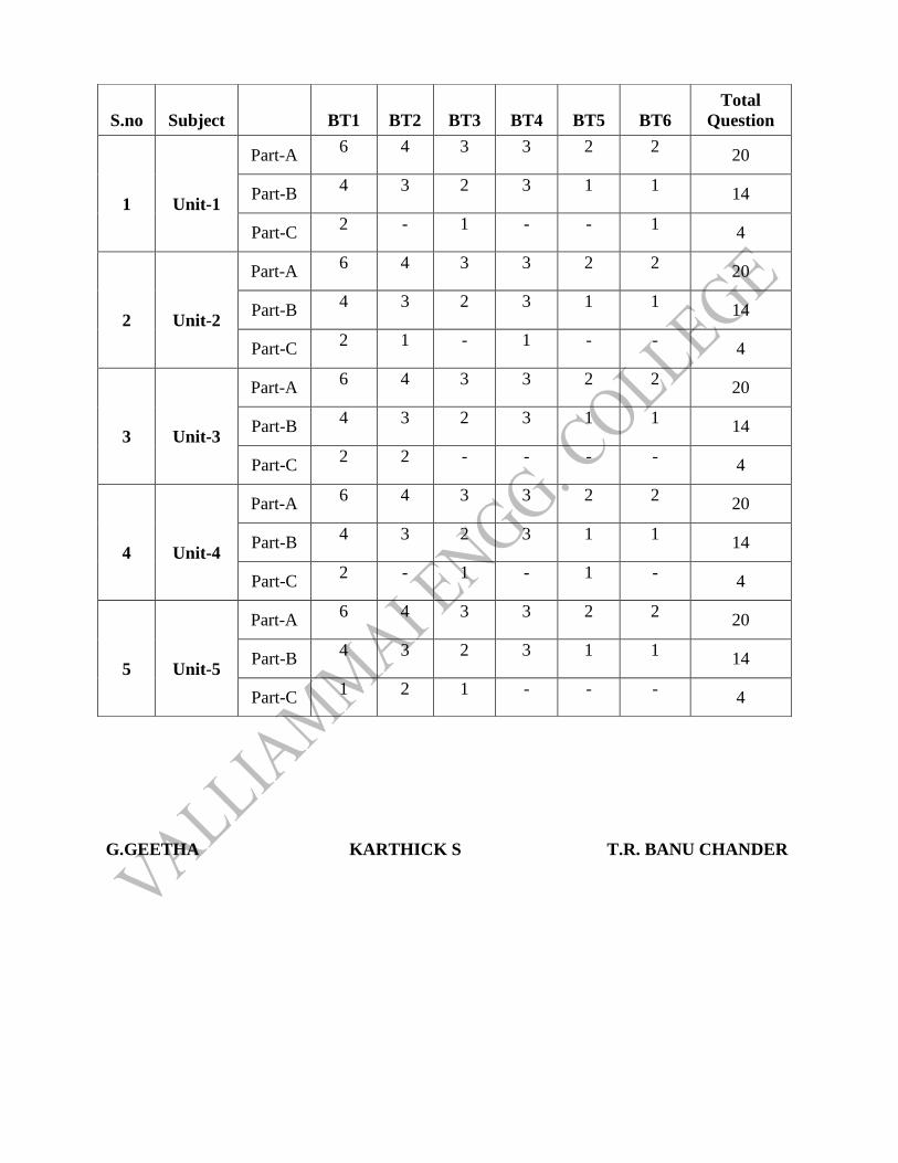
S.no
Subject
BT1
BT2
BT3
BT4
BT5
BT6
Total
Question
1
Unit-1
Part-A 6 4 3 3 2 2
20
Part-B 4 3 2 3 1 1
14
Part-C 2 - 1 - - 1
4
2
Unit-2
Part-A 6 4 3 3 2 2
20
Part-B 4 3 2 3 1 1
14
Part-C 2 1 - 1 - -
4
3
Unit-3
Part-A 6 4 3 3 2 2
20
Part-B 4 3 2 3 1 1
14
Part-C 2 2 - - - -
4
4
Unit-4
Part-A 6 4 3 3 2 2
20
Part-B 4 3 2 3 1 1
14
Part-C 2 - 1 - 1 -
4
5
Unit-5
Part-A 6 4 3 3 2 2
20
Part-B 4 3 2 3 1 1
14
Part-C 1 2 1 - - -
4