1 Valliammai Engineering College SRM Nagar, Kattankulathur - 603203 Department of Electrical and Electronics Engineering GE8261 – ENGINEERING PRACTICES LABORATORY ELECTRICAL LAB MANUAL I Year- II Semester Academic Year 2017-2018 (2017 Regulation)
Transcript
1
Valliammai Engineering College
SRM Nagar, Kattankulathur - 603203
Department of Electrical and Electronics Engineering
GE8261 – ENGINEERING PRACTICES LABORATORY
ELECTRICAL
LAB MANUAL
I Year- II Semester
Academic Year 2017-2018
(2017 Regulation)
2
GROUP B (ELECTRICAL)
III . ELECTRICAL ENGINEERING PRACTICE
1. Residential house wiring using switches, fuse, indicator, lamp and energy meter.
2. Fluorescent lamp wiring.
3.Stair case wiring
4. Measurement of Voltage, Current, Power and Power factor using R Load.
5. Measurement of energy using single phase energy meter.
6. Measurement of resistance to earth of electrical equipment.
Beyond the syllabus experiment
1. Different types of joints for making wiring.2. Characteristics of digital multimeter.3. Assembling a transformer.4. Bright and Dim lamp method.
3
INDEX
S.No Date Name of the Experiment Page No. Marks(10) Staff Sign
4
CIRCUIT DIAGRAM:
Name Plate Details
Switch
I=6A, V=240V
Incandescent Lamp
P=60W, V=230V,
Energy Meter
I=5-20A, V=240V, 1200 Revs/KWh
Fuse Rating
5
EX.NO:DATE:
RESIDENTIAL HOUSE WIRING USING SWITCHES, FUSE, INDICATOR, LAMPAND ENERGY METER
AIM:To Construct House wiring using switches, fuse, indicator, lamp and Energy Meter.
APPARATUS REQUIRED:
S.NO APPARATUS NAME RANGE / TYPE QUANTITY
1 Single way Switch 6A,240V 1
2 Fuse 5A 1
3 Indicator 5A 1
4 Incandescent Lamp 60 W 1
5 Energy meter 240V,5-20A 1
6 Connecting wires 1/18 SWG As per requirement
THEORY:Conductors, switches and other accessories should be of proper capable of carrying the
maximum current which will flow through them. The following table shows the rating fordifferent accessories. Conductors should be of copper or aluminum. In power circuit, wiringshould be designed for the load which it is supposed to carry. Power sub circuits should bekept separate from lighting and fan sub – circuits. Wiring should be done on the distributionsystem with main and branch distribution boards at convenient centers. Wiring should neat,with good appearance.
Wires should pass through a pipe or box, and should not twist or cross. The conductor is carried in a rigid steel conduit conforming to standards or
in a porcelain tube.
PROCEDURE:
1. Study the given wiring diagram.2. Make the location points for energy meter, fuse, indicator, main switch box, Switch board,lamp and ceiling rose.3. Draw the lines for wiring on the wooden board.4. Place the wires along with the line and fix.5. Fix the bulb holder, Switches, Ceiling rose, Socket in marked positions on the woodenboard.6. Connect the energy meter and main switch box in marked positions on the wooden board.7. Give a supply to the wires circuit.8. Test the working of light and socket.
RESULT:
6
Name Plate Details
Switch
I=6A, V=240V
Fluorescent Lamp
P=40W
Electronic Choke
P=40W,V=230V
Fuse Rating
7
EX.NO:DATE:
FLUORESCENT LAMP WIRING
AIM:
To make and check the fluorescent lamp wiring.
APPARATUS REQUIRED:
S.NO APPARATUS NAME RANGE / TYPE QUANTITY1 Fluorescent Lamp 40W 1 Set2 Connecting wires 1/18 SWG As per requirement
THEORY:Tube-lights, which are basically fluorescent, are the most commonly used high source
for illumination in houses, industries, commercial organizations and public utility services. Afluorescent lamp is a low pressure mercury and public utility services. A fluorescentdischarge lamp with internal surface coated with suitable fluorescent material. This lampconsists of glass tube provided at both ends with caps having two pins and oxide coatedtungsten filament. Tube contains argon or krypton gas to facilitate starting with smallquantity of mercury under low pressure. Fluorescent material, when subjected to electro-magnetic radiations of particular wavelength produced by the discharge through the mercuryvapor, gets excited and in turn gives out radiation at some other wave length which fallsunder visible spectrum. Thus, the secondary radiations from fluorescent powder increase theefficiency of the lamp. Tube lights in India are generally made either 61cm long 20 W ratingor 122 cm ling 40 W rating.
In order to make a tube light self starting, electronic choke is connected in the circuit.When switch S is closed, full supply voltage appears across the electrodes which are enclosedin a glasses bulb filled with argon gas. This voltage causes discharge in the argon gas withconsequent heating of the electrodes. Due to this heating, the electrode in the starter which ismade of bimetallic strip, bends and closes contact of the starter. At this stage, the choke, thefilaments of the tube and the starter become connected in series across the supply. A currentflows through the filaments and heats them. Meanwhile the argon discharge in the startertube disappears and after a cooling time, the electrodes of starter cause a sudden break in thecircuit. This causes a high value of induced EMF in the choke.
The induces EMF in the choke is applied across the tube light electrodes and isresponsible for initiating a gaseous discharge because initial heating has already created goodnumber of free electrons in the vicinity of electrodes. Thus, the tube light starts giving highoutput. Once the discharge through the tube is established, a much lower voltage than thesupply voltage is required to maintain it. A reduction in voltage available drop across thechoke. Power factor of the lamp is somewhat low and is about 0.5 lagging due to theinclusion of the electronic choke. A condenser, if connected across the supply, may improvethe P.F to about 0.95 lagging. The light output of the lamp is a function of its supply voltage.At reduced supply voltages, the lamp may click a start but may fail to hold because of nonavailability of required holding voltages across the tube. Higher than normal voltage reducesthe useful life of the tube light to a very great extent.
8
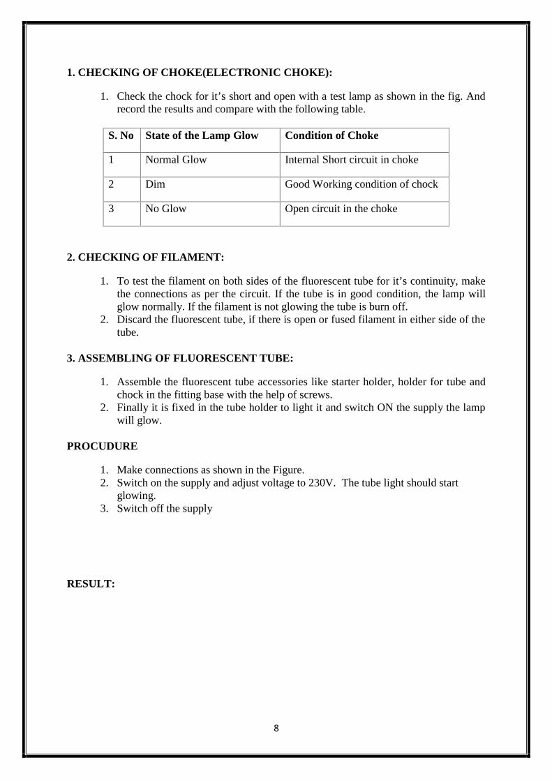
1. CHECKING OF CHOKE(ELECTRONIC CHOKE):
1. Check the chock for it’s short and open with a test lamp as shown in the fig. Andrecord the results and compare with the following table.
S. No State of the Lamp Glow Condition of Choke
1 Normal Glow Internal Short circuit in choke
2 Dim Good Working condition of chock
3 No Glow Open circuit in the choke
2. CHECKING OF FILAMENT:
1. To test the filament on both sides of the fluorescent tube for it’s continuity, makethe connections as per the circuit. If the tube is in good condition, the lamp willglow normally. If the filament is not glowing the tube is burn off.
2. Discard the fluorescent tube, if there is open or fused filament in either side of thetube.
3. ASSEMBLING OF FLUORESCENT TUBE:
1. Assemble the fluorescent tube accessories like starter holder, holder for tube andchock in the fitting base with the help of screws.
2. Finally it is fixed in the tube holder to light it and switch ON the supply the lampwill glow.
PROCUDURE
1. Make connections as shown in the Figure.2. Switch on the supply and adjust voltage to 230V. The tube light should start
To control the status of the given lamp by using 2 two – way switches
APPARATUS REQUIRED:
S.NO APPARATUS NAME RANGE / TYPE QUANTITY
1 Two way Switch 6A,240V 2
2 Incandescent Lamp 60 W,230V 1
3 Connecting wires 1/18 SWG As per requirement
PROCEDURE:
1. Place the accessories on the wiring board as per the circuit diagram.2. Place the P.V.C pipe and insert two wires into the P.V.C pipe.3. Take one wire connect one end to the phase side and other end to the middle point of
SPDT switch 14. Upper point of SPDT switch 1 is connected to the upper point of SPDT switch2.5. Lower point of SPDT 1 is connected to the lower point SPDT switch2.6. Another wire taken through a P.V.C pipe and middle point of SPDT switch 2 is
connected to one end of the lamp holder.7. Another end of lamp holder is connected to neutral line.8. Screw the accessories on the board and switch on the supply.9. Circuit is tested for all possible combination of switch position.
RESULT:
Thus the staircase wiring was done using two way switch.
11
Name Plate Details
Switch
I=6A, V=240V
Autotransformer
V=230V
Voltmeter
V=(0-300)V,MI
Ammeter
I=(0-10A),MI
Watt meter
V=300V, I= 10A, LPF
Variable Resistive Load
P=5KW
Fuse Rating
12
13
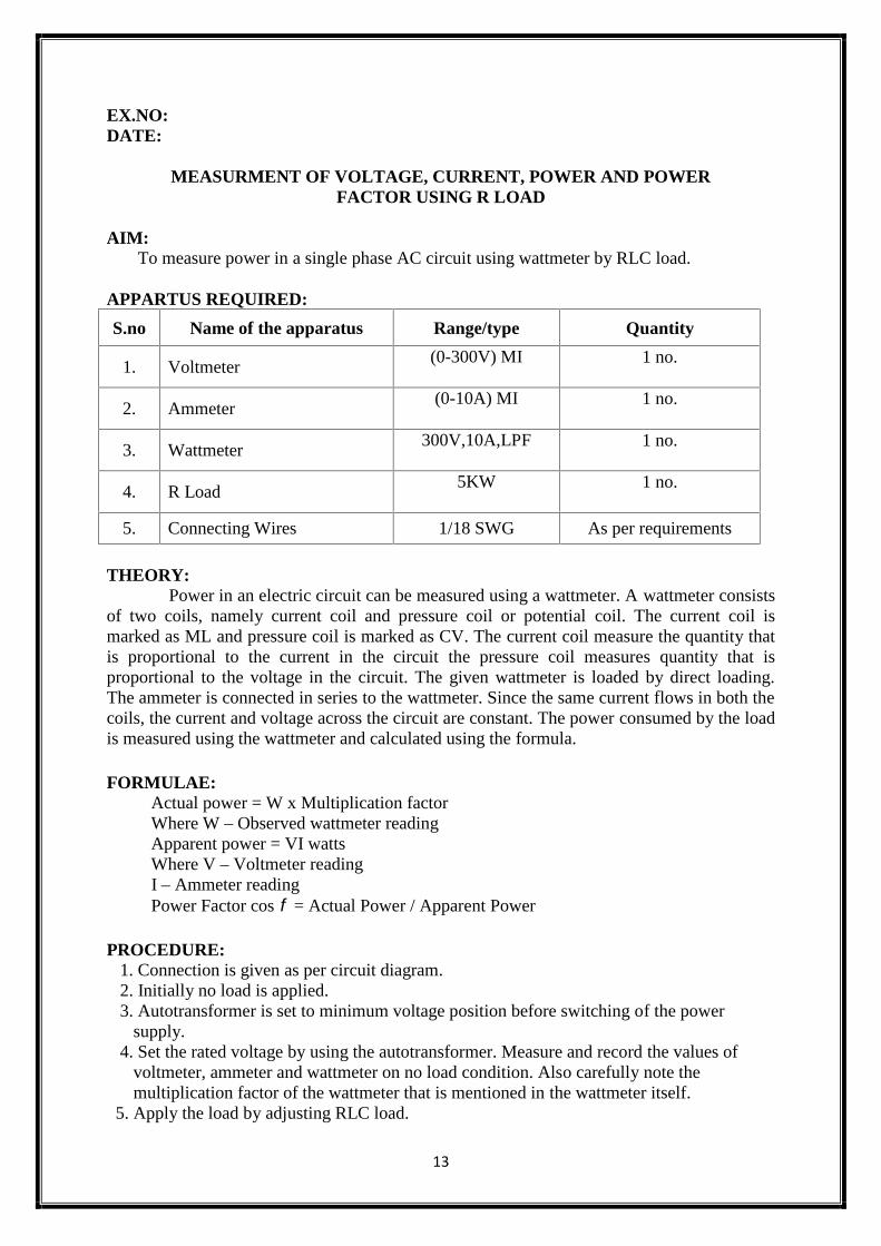
EX.NO:DATE:
MEASURMENT OF VOLTAGE, CURRENT, POWER AND POWERFACTOR USING R LOAD
AIM:To measure power in a single phase AC circuit using wattmeter by RLC load.
APPARTUS REQUIRED:
S.no Name of the apparatus Range/type Quantity
1. Voltmeter(0-300V) MI 1 no.
2. Ammeter(0-10A) MI 1 no.
3. Wattmeter300V,10A,LPF 1 no.
4. R Load5KW 1 no.
5. Connecting Wires 1/18 SWG As per requirements
THEORY:Power in an electric circuit can be measured using a wattmeter. A wattmeter consists
of two coils, namely current coil and pressure coil or potential coil. The current coil ismarked as ML and pressure coil is marked as CV. The current coil measure the quantity thatis proportional to the current in the circuit the pressure coil measures quantity that isproportional to the voltage in the circuit. The given wattmeter is loaded by direct loading.The ammeter is connected in series to the wattmeter. Since the same current flows in both thecoils, the current and voltage across the circuit are constant. The power consumed by the loadis measured using the wattmeter and calculated using the formula.
FORMULAE:Actual power = W x Multiplication factorWhere W – Observed wattmeter readingApparent power = VI wattsWhere V – Voltmeter readingI – Ammeter readingPower Factor cos = Actual Power / Apparent Power
PROCEDURE:1. Connection is given as per circuit diagram.2. Initially no load is applied.3. Autotransformer is set to minimum voltage position before switching of the power
supply.4. Set the rated voltage by using the autotransformer. Measure and record the values of
voltmeter, ammeter and wattmeter on no load condition. Also carefully note themultiplication factor of the wattmeter that is mentioned in the wattmeter itself.
5. Apply the load by adjusting RLC load.
14
MODEL CALCULATION:
15
6. Measure and record the values of voltmeter, ammeter and wattmeter.7. Repeat the steps 5 and 6 until the ammeter reading reaches 10A.8. After taking all the readings, reduce the load slowly to the minimum and bring thevoltage to minimum in the autotransformer. Switch off the power supply.9. Calculate the power factor and power by the given formula.
RESULT:Thus the power was calculated using wattmeter by RLC load.
16
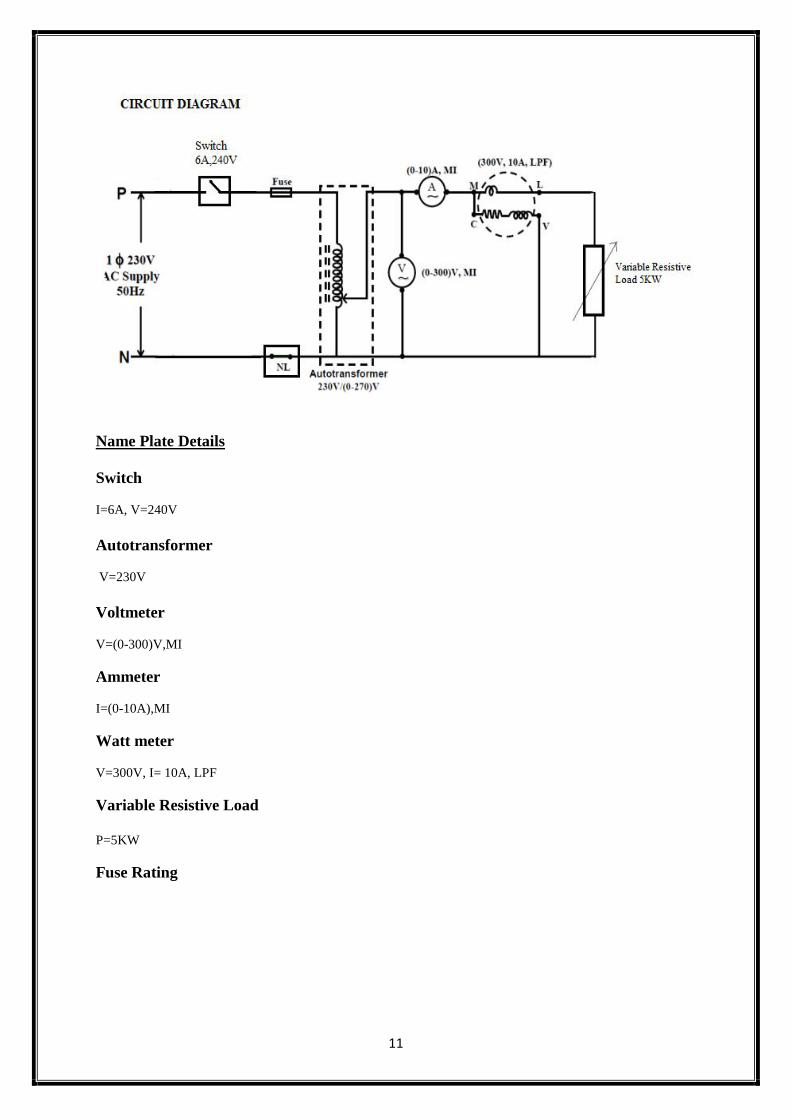
CIRCUIT DIAGRAM
Name Plate Details
Switch
I=6A, V=240V
Autotransformer
V=230V
Voltmeter
V=(0-300)V,MI
Ammeter
I=(0-10A),MI
Watt meter
V=300V, I= 10A, LPF
Variable Resistive Load
P=5KW
Energy Meter
I=5-20A, V=240V, 1200 Revs/KWh
Fuse Rating
17
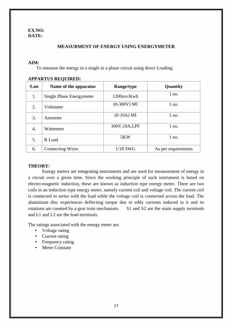
EX.NO:DATE:
MEASURMENT OF ENERGY USING ENERGYMETER
AIM:To measure the energy in a single in a phase circuit using direct Loading.
APPARTUS REQUIRED:
S.no Name of the apparatus Range/type Quantity
1. Single Phase Energymeter 1200rev/Kwh 1 no.
2. Voltmeter(0-300V) MI 1 no.
3. Ammeter(0-10A) MI 1 no.
4. Wattmeter300V,10A,LPF 1 no.
5. R Load5KW 1 no.
6. Connecting Wires 1/18 SWG As per requirements
THEORY:Energy meters are integrating instruments and are used for measurement of energy in
a circuit over a given time. Since the working principle of such instrument is based onelectro-magnetic induction, these are known as induction type energy meter. There are twocoils in an induction type energy meter, namely current coil and voltage coil. The current coilis connected in series with the load while the voltage coil is connected across the load. Thealuminium disc experiences deflecting torque due to eddy currents induced in it and itsrotations are counted by a gear train mechanism. S1 and S2 are the main supply terminalsand L1 and L2 are the load terminals.
The ratings associated with the energy meter are. Voltage rating Current rating Frequency rating Meter Constant
18
TABULAR COLUMN:
S.No
Voltmeterreading in
volts
AmmeterReadingin Amps
Wattmeterreading in Watts
Time takenfor 5
revolutions
TrueEnergyin KWh
Measuredenergy in
KWh% Error
Obs Act
MODEL CALCULATION:
19
FORMULAE:
Energy meter specification = 1500 rev / kWhTrue energy = Power (P) x time (s)
= P x t (ws)= P x t / 3600 x 1000 k
Measured energy = n / 1500 kWhWhere n - number of revolutions / sec
PROCEDURE:1. Connections are made as per the circuit diagram.2. Supply is given to the switch by closing the DPST switch.3. By adjusting the voltage is brought to the rated voltage.4. Load is switched on.5. Time taken for five revolutions in the energy meter is noted and the
Corresponding ammeter and voltmeter reading are noted.6. The above procedure is repeated for different load current and for fixed
number of revolutions.7. Then the load is gradually released and supply is switched OFF.8. The error is calculated and the graph is plotted between true energy and
Percentage of error.
`
RESULT:Thus the energy using single phase energy meter was measured.
20
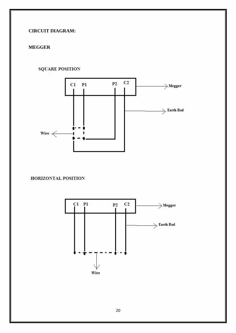
CIRCUIT DIAGRAM:
MEGGER
21
TABULATION:
S.NO Position Resistance (Ω)1 Square
2 Horizontal
3 Triangular
4
5
22
EX.NO:DATE:
MEASUREMENT OF RESISTANCE TO EARTH OFELECTRICAL EQUIPMENT
AIM:
To measure the resistance to earth / insulation resistance of the order of mega ohms.
THEORY:
For this experiment we have to use the Megger. It is an instrument for testing theinsulation resistance of the order of mega ohms.
PRINCIPLE:
A megger consists of an emf source and a voltmeter. The voltmeter scale is calibratedin ohms. In measurement, the emf of the self-contained source should be equal that of thesource used in calibration. The deflection of the moving system depends on the ratio of thecurrents in the coils and is independent of the applied voltage. The value of unknownresistance can be found directly from the scale of the instrument. Figure shows detaileddiagram of a megger. It consists of a hand driven dc generator a emf about 500V.thepermanent dc meter has two moving coils. First one is deflecting coil and another one iscontrolling coil. The deflecting coil is connected to the generator through a resistor R2. Thetorque due to the two coils opposes each other. It consists of three terminals E (earthterminal) and L (line terminal) and G (guard wire terminal).
OPERATION:
When the terminals are open circuited, no current flows through the deflecting coil.The torque to the controlling coil moves the pointer to one end of the scale. When theterminals are short circuited, the torque due to the controlling coil and the pointer is deflectedto the other end of the scale i.e. zero mark. In between the two extreme positions the scale iscalibrated to indicate the value of unknown resistance directly. The unknown insulationresistance is the combination of insulation volume resistance and surface leakage resistance.The guard wire terminal makes the surface leakage current to bypass the instrument henceonly insulation resistance is measured.
23
RESULT:
Thus the earth resistance in
Horizontal position =Square position =Triangular position =
24
EX.NO:DATE:
DIFFERENT TYPES OF JOINTS FOR MAKING WIRINGAIM:
To study the different types of electrical joints
APPARTUS REQUIRED:
S.No Name of the apparatus Range/type Quantity
1 Connecting wire 1/18 SWG As per requirement
2 Wire cutter - 1
3 battery in battery holder with metal tags 1.5 V 1
4 Soldering iron and stand - 1
5 Rosin-free flux cored solder - As per requirement
6 Voltmeter (0-100V) 1
THEORY:Electrical joints are the joints that connect the various components in an electrical
circuit. They can be permanent (soldered or crimped), or temporary (bolted, clamped orplugged in). One of the most common permanent joints is solder. Soldering uses tin alloysolder, which has a low melting temperature. This is melted using a soldering iron and coatedon the two components being joined.PROCEDURE:
1. Use a pair of wire strippers to take 1 cm of insulation off the end of each lead.2. Turn the soldering iron on and wait for it to get hot.3. When the iron is hot, clean the bit using the wet sponge. Make sure its surface is coated
with a thin film of fresh solder by carefully touching some solder.4. Touch the iron against one of the tags on the battery holder so it warms up. At the same
time touch some solder against the tag so it melts and produces a thin layer of solder onthe tag.
5. Do the same for the bared end of the lead (this process is sometimes called tinning).6. Touch the soldering iron against the tag and, at the same time, bring the bare end of the
lead into contact with the tag.7. Remove the bit as soon as there is a layer of molten solder joining the wire to the tag.8. Be careful not to move the joint while it cools down.9. A good solder joint is shiny. If it's rough, touch the bit of the iron to the tag and add
some solder until you get a better joint.10. Clean the bit of the soldering iron on the wet sponge and repeat with the other tag and
lead.11. To check the soldered joints are working, connect the plug sockets to the voltmeter (see
circuit diagram) and check the voltage across the battery.RESULT:
25
CIRCUIT DIAGRAM:
(A)
(B)
26
EX.NO:DATE:
CHARACTERISTICS OF DIGITAL MULTIMETER
AIM:
i. To measure the resistance of a resistor using a digital multimeterii. To measure the DC voltage using a digital multimeter
iii. To measure the current in an electrical circuit using a digital multimeter
APPARATUS REQUIREDS.no Name of the apparatus Range/type Quantity
1 Digital multimeter with probes - 1
2 Resistor 6.8Ω,100Ω, 2.2KΩ, 33KΩ,270Ω, 1MΩ, 1KΩ
1
3 Regulated power supply (0-30V) 1
4 Bread board - 1
5 Voltmeter (0-30V) MI 1
THEORY:A digital multimeter is an instrument which is used for measuring various electrical
quantities like DC voltage, AC voltage, DC current, AC current and resistance. In digitalmultimeters the measurement result is given in numerical form. The most importantcomponent in it is an analog-to-digital (A/D) converter, which converts the measured (orfrom it electronically formed) DC voltage into numerical presentation.
In addition to the usual multimeter functions, microprocessor technology has enabledsome new features in digital multimeters. Readout holding 'freezes' the displayed valueinstantly after the probe touches the measurement point; thus the user may concentrate onaligning the testing wires to the measured object. Short-circuit testing beeps when theresistance is below a certain limit. A multimeter with recording of minimum and maximumvalues can be left to record minimum- maximum values on its own, no matter whether theyare voltages, currents, resistances or temperatures. Peak value holding is useful, when themeasured circuit has voltage transients or impulse currents of less than one period’s length.The use of offset makes it possible to record a signal value into the meter’s memory andadding this value to or subtracting it from the following values; in this way two differentvoltages can be compared quickly. When offset is used together with dB-function, the dB-values can be read directly on the meter. Offset can also be used for the compensation of themeasurement error caused by the resistance of the measurement leads. Many multimeters canalso measure frequency. Many meters select the measurementrange automatically.
27
i. Measurement of resistance using a digital multimeter
TABULAR COLUMN:
S.No Nominal value Ohmmeter reading Percentage difference
1 6.8Ω
2 100Ω
3 2.2KΩ
4 33KΩ
5 270Ω
6 1MΩ
7 1KΩ
ii. Measurement of DC voltage using a digital multimeter
TABULAR COLUMN:
S.No Power supply voltage Digital multimeter reading
1 0.5
2 2
3 5
4 15
5 30
28
PROCEDURE:
1. Connect the resistor into the bread broad2. Connect the Black Probe to the COM terminal and Red Probe to the terminal marked
with “Ω.”3. Set the meter to “Ω.”4. Connect the Black Probe to one end of the resistor , now connect the Red Probe to the
other end of the resistor5. Set the meter to “Ω” function6. Now that the meter has given a reading7. compare the difference between the measured resistance and the nominal resistance8. The percentage difference is calculated by:
9. Note the readings and find the value of resistance.
PROCEDURE:1. The voltmeter is placed in parallel with the circuit element whose voltage is to be
measured2. Locate the voltage adjustment knob, current adjustment knob, and the power switch
on the power supply3. Before you turn on the power supply rotate both the current and voltage adjustment
knobs to the left.4. Turn on the power supply and Note that both readings of current and voltage are at
zero.5. Now rotate the current knob about half way and set the voltage adjustment knob for a
reading of 0.5 V.6. Take the Digital multimeter and connect the Black Probe to the COM terminal on the
meter and Red Probe to the terminal marked with "V" on the meter.7. Set the meter to V---- function.8. The Red Probe is connected to the positive (+) voltage terminal of the power supply
and the Black Probe to the negative (-) voltage terminal of the power supply.9. Set the power supply to the following voltages as stated in the Tabular column above
and record the data’s.
iii. Measurement of current in an electrical circuit using a digital multimeter
PROCEDURE:1. Construct the circuit shown in the circuit diagram (A)2. Set the digital multimeter selector switch to A--.3. Connect the Black Probe to the COM terminal of the digital multimeter and the Red
Probe to the digital multimeter terminal marked 300mA.4. Insert the meter as shown in circuit diagram (B)5. Now connect the source and read the current value.
RESULT
29
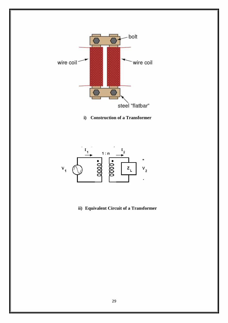
i) Construction of a Transformer
ii) Equivalent Circuit of a Transformer
30
EX.NO:DATE:
ASSEMBLING A TRANSFORMER
AIM
The learning objectives of Assembling of Transformer are
Effects of electromagnetism. Effects of electromagnetic induction. Effects of magnetic coupling on voltage regulation. Effects of winding turns on "step" ratio.
APPARATUS REQUIRED
Power transformer, 120VAC step-down to 12VAC Terminal strip with at least three terminals. Household wall-socket power plug and cord. Line cord switch. Fuse and fuse holder
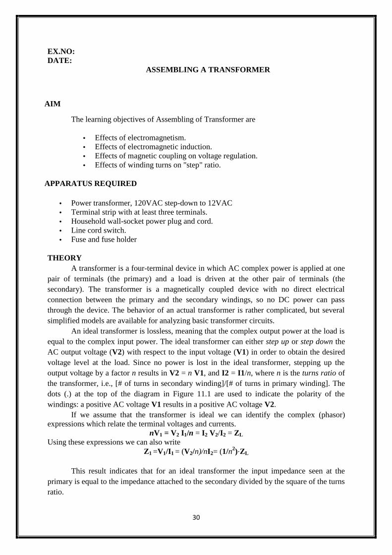
THEORYA transformer is a four-terminal device in which AC complex power is applied at one
pair of terminals (the primary) and a load is driven at the other pair of terminals (thesecondary). The transformer is a magnetically coupled device with no direct electricalconnection between the primary and the secondary windings, so no DC power can passthrough the device. The behavior of an actual transformer is rather complicated, but severalsimplified models are available for analyzing basic transformer circuits.
An ideal transformer is lossless, meaning that the complex output power at the load isequal to the complex input power. The ideal transformer can either step up or step down theAC output voltage (V2) with respect to the input voltage (V1) in order to obtain the desiredvoltage level at the load. Since no power is lost in the ideal transformer, stepping up theoutput voltage by a factor n results in V2 = n V1, and I2 = I1/n, where n is the turns ratio ofthe transformer, i.e., [# of turns in secondary winding]/[# of turns in primary winding]. Thedots (.) at the top of the diagram in Figure 11.1 are used to indicate the polarity of thewindings: a positive AC voltage V1 results in a positive AC voltage V2.
If we assume that the transformer is ideal we can identify the complex (phasor)expressions which relate the terminal voltages and currents.
nV1 = V2 I1/n = I2 V2/I2 = ZL
Using these expressions we can also writeZ1 =V1/I1 = (V2/n)/nI2= (1/n2)⋅ZL
This result indicates that for an ideal transformer the input impedance seen at theprimary is equal to the impedance attached to the secondary divided by the square of the turnsratio.
31
Wrap two, equal-length bars of steel with a thin layer of electrically-insulating tape. Wrapseveral hundred turns of magnet wire around these two bars. You may make these windingswith an equal or unequal number of turns, depending on whether or not you want thetransformer to be able to "step" voltage up or down. I recommend equal turns to begin with,then experiment later with coils of unequal turn count. Join those bars together in a rectanglewith two other, shorter, bars of steel. Use bolts to secure the bars together (it is recommendedthat you drill bolt holes through the bars before you wrap wire around them).
Check for shorted windings (ohmmeter reading between wire ends and steel bar) afteryou're finished wrapping the windings. There should be no continuity (infinite resistance)between the winding and the steel bar. Check for continuity between winding ends to ensurethat the wire isn't broken open somewhere within the coil. If either resistance measurementsindicate a problem, the winding must be re-made. Measure the output voltage (secondarywinding) of your transformer with an AC voltmeter. Connect a load of some kind (light bulbsare good!) to the secondary winding and re-measure voltage. Note the degree of voltage "sag"at the secondary winding as load current is increased. Loosen or remove the connecting boltsfrom one of the short bar pieces, thus increasing the reluctance (analogous to resistance) ofthe magnetic "circuit" coupling the two windings together. Note the effect on output voltageand voltage "sag" under load.
RESULT:
32
i) Series Connection
33
EX.NO:DATE:
BRIGHT AND DIM LAMP METHOD
AIM
To connect batteries in Series and Parallel to perform Bright and Dim Lamp methodat different voltage levels
APPARATUS REQUIRED
One 9-volt battery Four 6-volt batteries 12-volt light bulb, 25 or 50 watt Lamp socket
SERIES CONNECTION
Connecting components in series means to connect them in-line with each other, sothat there is but a single path for electrons to flow through them all. If you connect batteriesso that the positive of one connects to the negative of the other, you will find that theirrespective voltages add. Measure the voltage across each battery individually as they areconnected, then measure the total voltage across them.
PARALLEL CONNECTION
By connecting one 6-volt battery to the lamp. The lamp, designed to operate on 12volts, should glow dimly when powered by the 6-volt battery. Use your voltmeter to readvoltage across the lamp.
The voltmeter should register a voltage lower than the usual voltage of the battery. Ifyou use your voltmeter to read the voltage directly at the battery terminals, you will measurea low voltage there as well. Why is this? The large current drawn by the high-power lampcauses the voltage at the battery terminals to "sag" or "droop," due to voltage dropped acrossresistance internal to the battery. We may overcome this problem by connecting batteries inparallel with each other, so that each battery only has to supply a fraction of the total currentdemanded by the lamp.
34
ii) Parallel Connection
iii) Series-Parallel Connection
35
Parallel connections involve making all the positive (+) battery terminals electricallycommon to each other by connection through jumper wires, and all negative (-) terminalscommon to each other as well. Add one battery at a time in parallel, noting the lamp voltagewith the addition of each new, parallel-connected battery.By breaking the circuit for just onebattery, and inserting our ammeter within that break, we intercept the current of that onebattery and are therefore able to measure it. Measuring total current involves a similarprocedure: make a break somewhere in the path that total current must take, then insert theammeter within than break. To obtain maximum brightness from the light bulb, a series-parallel connection is required. Two 6-volt batteries connected series-aiding will provide 12volts.