VALLIAMMAI ENGINEERING COLLEGE SRM Nagar, Kattankulathur – 603 203 DEPARTMENT OF MECHANICAL ENGINEERING QUESTION BANK IV SEMESTER – ME6401 - KINEMATICS OF MACHINERY Regulation – 2017 Academic Year 2017 – 18 Prepared by Mr. K. ARUMUGAM, Assistant Professor Mr. K. VELAVAN, Assistant Professor Mr. R. SRINIVASAN, Assistant Professor Mr. K.P. MANIKANDAN, Assistant Professor
Transcript
VALLIAMMAI ENGINEERING COLLEGE
SRM Nagar, Kattankulathur – 603 203
DEPARTMENT OF MECHANICAL ENGINEERING
QUESTION BANK
IV SEMESTER – ME6401 - KINEMATICS OF MACHINERY
Regulation – 2017
Academic Year 2017 – 18
Prepared by
Mr. K. ARUMUGAM, Assistant Professor
Mr. K. VELAVAN, Assistant Professor
Mr. R. SRINIVASAN, Assistant Professor
Mr. K.P. MANIKANDAN, Assistant Professor
VALLIAMMAI ENGINEERING COLLEGE SRM Nagar, Kattankulathur – 603 203.
DEPARTMENT OF MECHANICAL ENGINEERING
QUESTION BANK
SUBJECT : ME6401 - KINEMATICS OF MACHINERY
SEM / YEAR : IV / II
UNIT I - BASICS OF MECHANISMS
UNIT-I SYLLABUS Classification of mechanisms – Basic kinematic concepts and definitions – Degree of freedom, Mobility – Kutzbach criterion, Grubler’s criterion – Grashof’s Law – Kinematic inversions of four-bar chain and slider crank chains – Limit positions – Mechanical advantage – Transmission Angle –Description of some common mechanisms – Quick return mechanisms, Straight line generators, Universal Joint – rocker mechanisms.
PART - A ( 2 MARKS )
Sl.No QUESTIONS LEVEL COMPETENCE
1. Define ‘degrees of freedom’.
BT4 Analyze
2. What is meant by spatial mechanism? BT2 Understand
3. Classify the constrained motion.
BT1 Remember
4. What is meant by number synthesis?
BT5 Evaluate
5. What are the some important inversions of four chain mechanism? BT1 Remember
6. What is toggle position?
BT1 Remember
7. What is pantograph?
BT4 Analyze
8. What are the applications of single slider crank mechanism?
BT2 Understand
9. Give some examples for kinematics pairs.
BT1 Remember
10. Discuss Elliptical trammel
BT1 Remember
11. What is movability? BT5 Evaluate
12. What is mobility?
BT1 Remember
13. What is meant by transmission angle?
BT4 Analyze
14. What is meant by Ackermann steering? BT1 Remember
15. Write down the Grashof’s Law for a four bar mechanism? BT2 Understand
16. Explain the working principle of bicycle bells.
BT1 Remember
17. What is meant by motion adjustment mechanism?
BT2 Understand
18. Whether a cycle chain is kinematic chain or not? BT1 Remember
19. Define instantaneous centre BT2 Understand
20. What is instantaneous axis? BT6 Create
PART - B ( 13 MARKS )
Sl.No QUESTIONS LEVEL COMPETENCE
1. a) Describe different types of Link.
b) Classify and explain the Kinematic pair. BT2 Understand
2. Draw and Describe inversion of four bar chain. BT1 Remember
3. Explain the inversion of Single Slider Crank Chain. BT2 Understand
4. Explain the inversion of Double Slider crank chain. BT4 Analyze
5. a) Explain the offset slider crank mechanism.
b) Explain Straight line mechanism with neat sketch. BT3 Apply
6. Describe the working of Oldham’s coupling with a neat sketch and state its application
BT4 Analyze
7. Discuss the steering gear mechanism with neat sketch. BT1 Remember
8. Explain the working of Whitworth quick return mechanism with a neat
sketch. BT2 Understand
9. Explain the working of crank and slotted lever quick return motion
mechanism with a neat sketch. BT6 Create
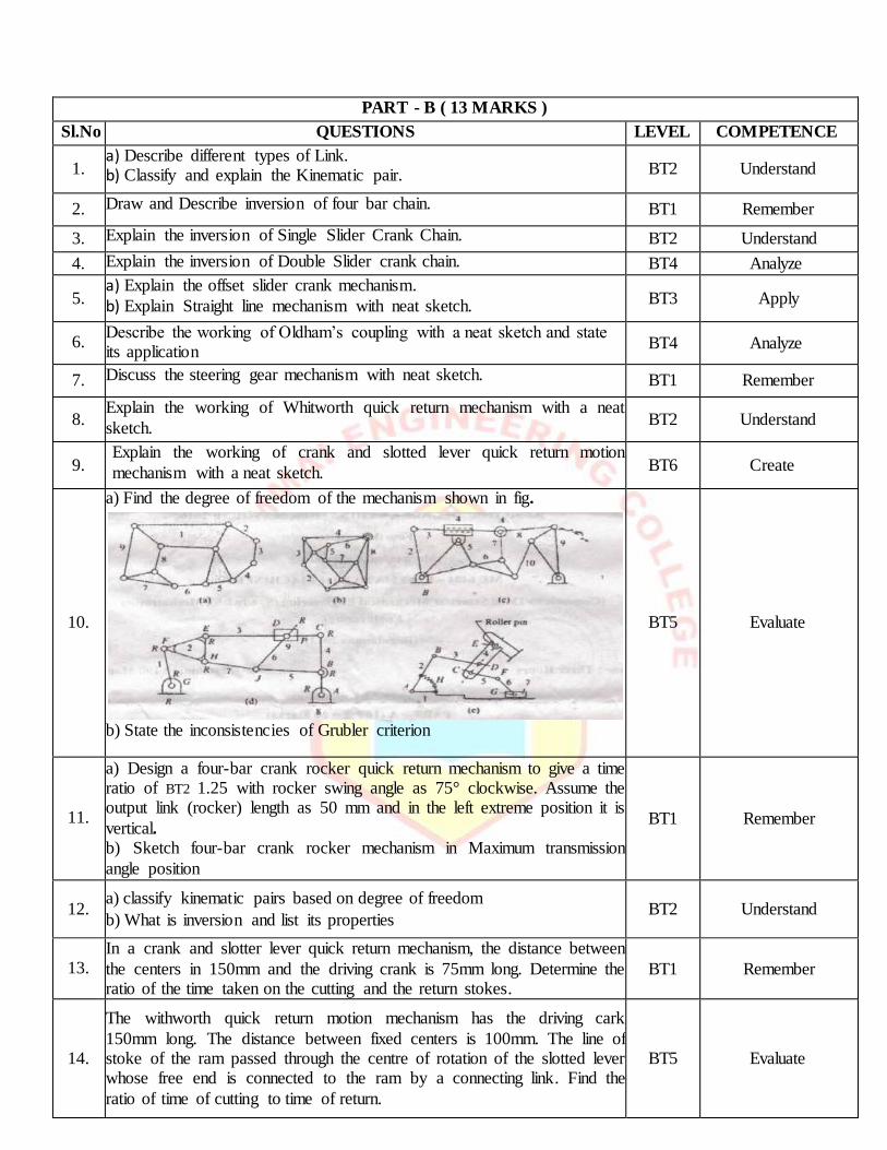
10.
a) Find the degree of freedom of the mechanism shown in fig.
b) State the inconsistencies of Grubler criterion
BT5 Evaluate
11.
a) Design a four-bar crank rocker quick return mechanism to give a time ratio of BT2 1.25 with rocker swing angle as 75° clockwise. Assume the output link (rocker) length as 50 mm and in the left extreme position it is
vertical. b) Sketch four-bar crank rocker mechanism in Maximum transmission
angle position
BT1 Remember
12. a) classify kinematic pairs based on degree of freedom
b) What is inversion and list its properties BT2 Understand
13. In a crank and slotter lever quick return mechanism, the distance between
the centers in 150mm and the driving crank is 75mm long. Determine the ratio of the time taken on the cutting and the return stokes.
BT1 Remember
14.
The withworth quick return motion mechanism has the driving cark
150mm long. The distance between fixed centers is 100mm. The line of stoke of the ram passed through the centre of rotation of the slotted lever whose free end is connected to the ram by a connecting link. Find the
ratio of time of cutting to time of return.
BT5 Evaluate
PART - C
Sl.No QUESTIONS LEVEL COMPETENCE
1.
A crank and slotter lever quick return mechanism, the distance between
the fixed centers O and C is 200mm.the driving crank CP is 75mm long. The pin Q on the slotter lever, 360 mm for the fulcrum O, is connected by
a link QR 100mm long, to a pin R on the ram. The line of stoke of R is perpendicular to OC and intersect OC produced at a point 150mm from C. Determine ratio of times taken on the cutting and the return stokes.
BT2 Understand
2.
Sketch and describe the working of two different types of quick return mechanism. Give examples of their application. Derive an expression for
the ratio of time taken in forward and return stoke for one of this mechanism.
BT1 Remember
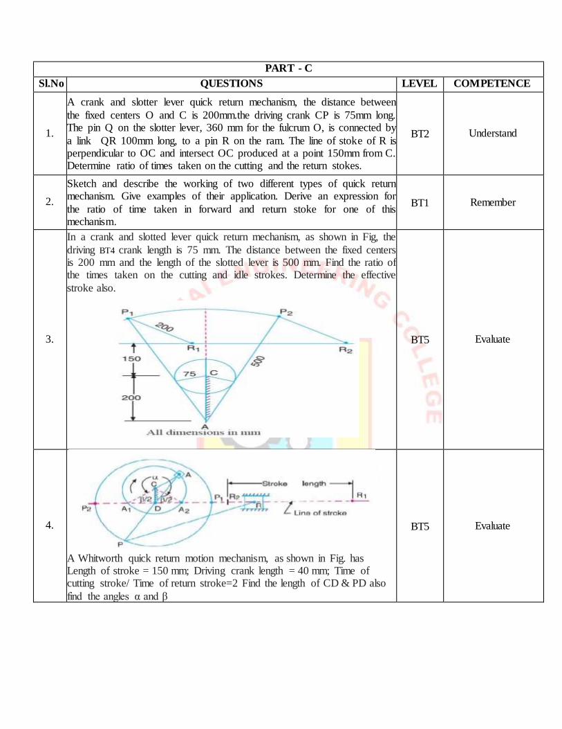
3.
In a crank and slotted lever quick return mechanism, as shown in Fig, the
driving BT4 crank length is 75 mm. The distance between the fixed centers is 200 mm and the length of the slotted lever is 500 mm. Find the ratio of the times taken on the cutting and idle strokes. Determine the effective
stroke also.
BT5 Evaluate
4.
A Whitworth quick return motion mechanism, as shown in Fig. has Length of stroke = 150 mm; Driving crank length = 40 mm; Time of cutting stroke/ Time of return stroke=2 Find the length of CD & PD also
find the angles α and β
Find the lengths of CD and PD. Also determine the angles α and β.
BT5 Evaluate
UNIT II: KINEMATICS OF LINKAGE MECHANISMS
UNIT-II SYLLABUS
Displacement, velocity and acceleration analysis of simple mechanisms – Graphical method– Velocity and
acceleration polygons – Velocity analysis using instantaneous centres – kinematic analysis of simple mechanisms – Coincident points – Coriolis component of Acceleration – Introduction to linkage synthesis problem.
PART - A ( 2 MARKS )
Sl.No QUESTIONS LEVEL COMPETENCE
1. What is kinematic analysis? BT2 Understand
2. Write down the different types of motion. BT1 Remember
3. Define Kennedy’s theorem. BT6 Create
4. What are properties of instantaneous center? BT1 Remember
5. What is the difference between velocity and speed BT5 Evaluate
6. What is configuration diagram? BT4 Analyze
7. Write the different types of graphical method. BT2 Understand
8. What is acceleration? BT1 Remember
9. What is deceleration? BT6 Create
10. What is angular velocity ratio theorem? BT1 Remember
11. What is meant by coincident points? BT3 Apply
12. What is centrode? BT5 Evaluate
13. What is space centrode? BT1 Remember
14. What is Body centrode? BT4 Analyze
15. What is Instantaneous axis? BT2 Understand
16. What is axode? BT5 Evaluate
17. Write down the different types of Instantaneous centres. BT6 Create
18. Explain any two methods of reducing interference in gears. BT4 Analyze
19. What is the effects of centrifugal tension in belt drives? BT3 Apply
20. Compare the two components of acceleration. BT1 Remember
PART - B( 13 MARKS )
Sl.No QUESTIONS LEVEL COMPETENCE
1.
The Crank of a slider crank mechanisms rotates clockwise at a Constant
speed of 300 rpm. The crank is 125 mm and connecting rod is 600 mm
long. Determine 1. Linear velocity and acceleration of the mid-Point of
the connecting rod, and 2. Angular velocity and angular acceleration of
the connecting rod, at a crank angle of 45° from inner dead center
position.
BT3
Apply
2.
In a four link mechanism, the dimensions of the links are AB=200 mm, BC=400mm, CD=450 mm and AD=600mm. At the instant when
DAB=90°, the link AB has angular velocity of 36 rad/s in the clockwise direction. Determine (i) The velocity of point C, (ii) The velocity of point E on the link BC When BE =200 mm (iii) the angular velocities of links
BC and CD, iv) acceleration of link of link BC.
BT2
Understand
3.
The dimensions of the various links of a mechanism, as shown in fig. are as follows: OA=300 mm; AB=1200; BC=450 mm and CD=450 mm. if
the crank OA rotates at 20 rpm. in the anticlockwise direction and gives motion to the sliding blocks B and D, find, for given configuration: (1)
BT1
Remember
Velocity of sliding at B and D, (2) Angular velocity of CD (3) Linear acceleration of D and (4) angular acceleration of CD.
4.
a)Derive the expressions for Velocity and acceleration of piston in
reciprocating steam engine mechanism with neat sketch
b).Derive the expression for Coriollis component of acceleration with
neat sketch.
BT6
Create
5.
In a slider crank mechanism, the length of the crank and the connecting rod are 100 mm and 400 mm respectively. The crank [position is 45° from IDC, the crank shaft speed is 600 rpm. clockwise. Using analytical
method Determine (1) Velocity and acceleration of the slider, and (2) Angular velocity and angular acceleration of the connecting rod.
BT4
Analyze
6.
Locate all instantaneous centers of the slider crank mechanism; the
length of crank OB and Connecting rod AB are 125 mm and 500 mm respectively. The crank speed is 600 rpm clockwise. When the crank has turned 45° from the IDC. Determine (i) velocity of. Slider’ A’ (ii)
Angular Velocity of connecting rod ‘AB’.
BT5 Evaluate
7.
In the mechanism shown in figure, the crank OA rotates at 20 rpm anticlockwise and gives motion of sliding blocks B and D. The
dimensions of various links are OA =300mm, AB = 1200 mm, BC = 450 mm and CD = 450 mm. For the given configuration determine i)
velocities of sliding at B and D, ii) angular velocity of CD iii) Linear acceleration of D and iv) angular acceleration of CD.
BT3 Apply
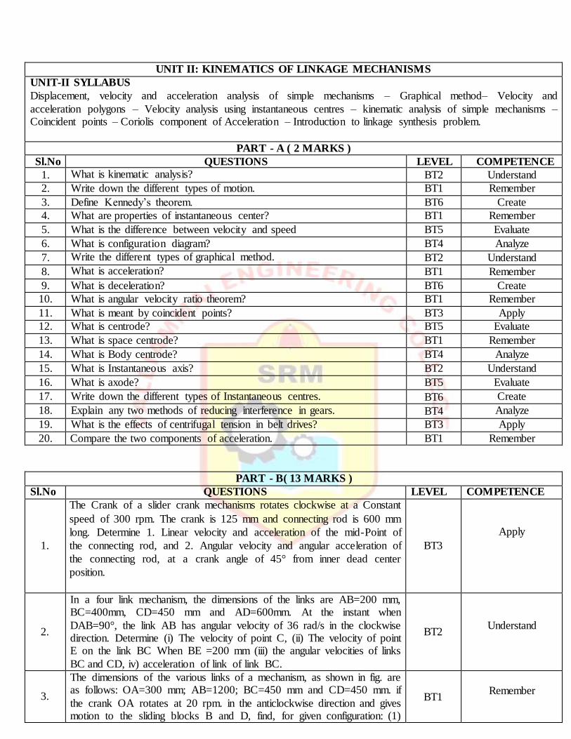
8.
The crank and connecting rod of a theoretical steam engine are 0.5 m
and 2m long respectively. The crank makes 180 rpm in the clockwise direction. When it has turned 450 from the inner dead center
position, determine: a) Velocity of piston b) Angular velocity of connecting rod. C) Velocity of point E on the connecting rod 1.5m from the gudgeon pin. D) Velocity of rubbing at the pins of the crank
shaft, crank and crank cross head when the diameters of their pins are 50mm and 60mm and 30mm respectively.
BT4 Analyze
9.
A four-bar mechanism has the following link length in mm. Input, A0A = 25, AB = 70, output B0B=45 and frame A0B0 = 60. Coupler point A is above and B is below the horizontal frame link A0B0, respectively.
When the input link is in an angular position of 1050 counter clockwise from the frame link, draw the four bar mechanism and locate all the
instantaneous centers .if the input link rotates With a constant angular velocity of 2.5 rad/sec clockwise, determine the linear velocity of B of the output link and the angular velocity of the output link.
BT2 Understand
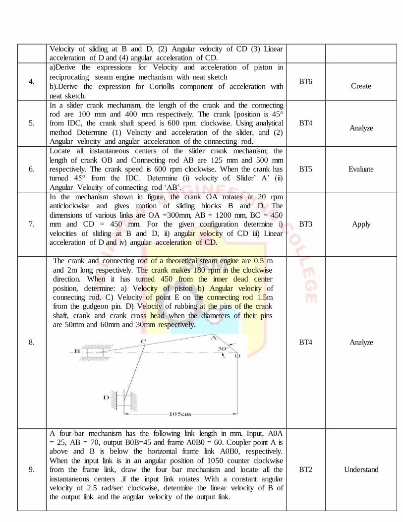
10.
In a steam engine mechanism shown in figure a) the crank AB rotates at
200 rpm. The BT4 dimensions of various links are AB = 12cm, BC =
48cm, CD = 18cm and DE =36cm, EF = 12 cm and FP = 36cm. Find the
velocities of C, D, E, F and P.
BT2 Understand
11.
In a slider crank mechanism, the length of crank OB and connecting rod AB are 125mm and 500mm respectively. The centre of gravity G of the connecting rod is 275mm from the side A. the crank speed is 600rpm
clockwise. When the crank has turned 45° from the inner dead centre position, determine: 1, velocity of a slider A, 2.velocity of point G, and 3.
Angular velocity of the connecting rod AB.
BT1 Remember
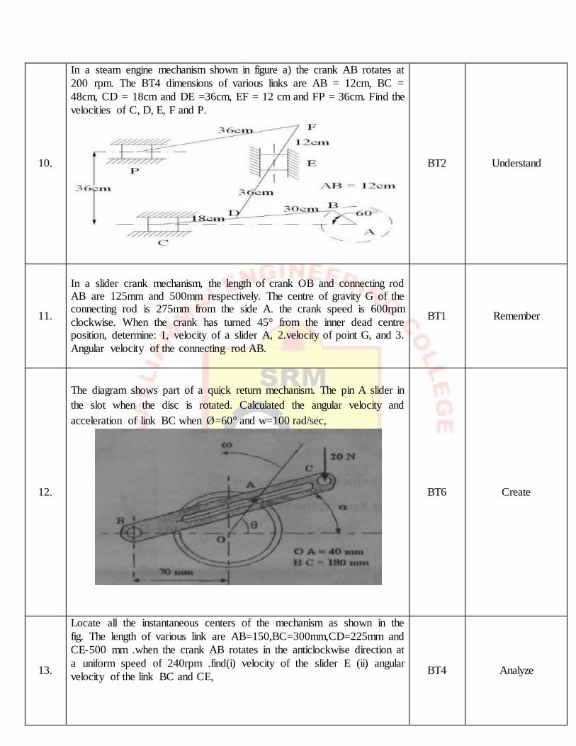
12.
The diagram shows part of a quick return mechanism. The pin A slider in
the slot when the disc is rotated. Calculated the angular velocity and
acceleration of link BC when Ø=60° and w=100 rad/sec,
BT6 Create
13.
Locate all the instantaneous centers of the mechanism as shown in the
fig. The length of various link are AB=150,BC=300mm,CD=225mm and
CE-500 mm .when the crank AB rotates in the anticlockwise direction at
a uniform speed of 240rpm .find(i) velocity of the slider E (ii) angular
velocity of the link BC and CE,
BT4 Analyze
14.
A single cylinder rotary engine is shown in the fig shows below. OA is
the fixed link, 200mm long, OB is the connection rod is 520 mm long.
The line of the stroke is along AD and the instant is inclined at 30° to the
vertical. The body of the engine consisting of cylinder rotates at the
uniform speed of 400rpm and about fixed centre A. determine the
acceleration of slider B and the angular acceleration of connecting rod.
BT5 Evaluate
PART - C ( 15 MARKS )
Sl.No QUESTIONS LEVEL COMPETENCE
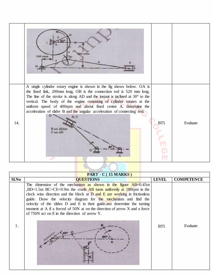
1.
The dimension of the mechanism as shown in the figure AB=0.45m ,BD=1.5m BC=CE=0.9m the crank AB turns uniformly at 180rpm in the clock wise direction and the block at D and E are working in frictionless
guide. Draw the velocity diagram for the mechanism and find the velocity of the slides D and E in their guide.aso determine the turning
moment at A if a forced of 50N at on the direction of arrow X and a force of 750N act on E in the direction of arrow Y.
BT5 Evaluate
2. By analytical method, derive the velocity and acceleration for the reciprocating steam engine.
BT4 Analyze
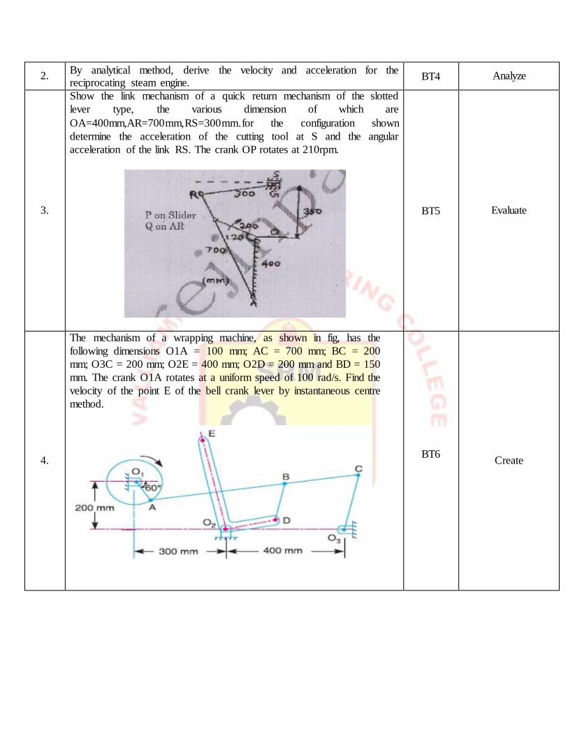
3.
Show the link mechanism of a quick return mechanism of the slotted
lever type, the various dimension of which are
OA=400mm,AR=700mm,RS=300mm.for the configuration shown
determine the acceleration of the cutting tool at S and the angular
acceleration of the link RS. The crank OP rotates at 210rpm.
BT5 Evaluate
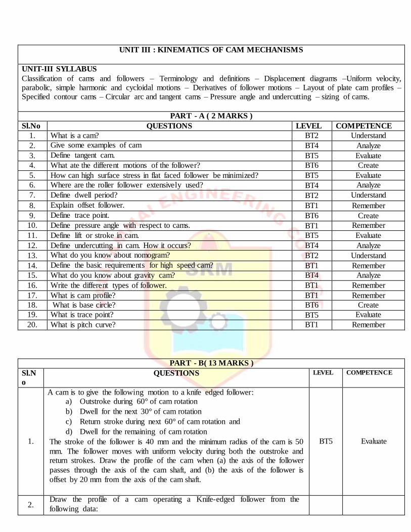
4.
The mechanism of a wrapping machine, as shown in fig, has the
following dimensions O1A = 100 mm; AC = 700 mm; BC = 200
mm; O3C = 200 mm; O2E = 400 mm; O2D = 200 mm and BD = 150
mm. The crank O1A rotates at a uniform speed of 100 rad/s. Find the
velocity of the point E of the bell crank lever by instantaneous centre
method.
BT6
Create
UNIT III : KINEMATICS OF CAM MECHANISMS
UNIT-III SYLLABUS
Classification of cams and followers – Terminology and definitions – Displacement diagrams –Uniform velocity, parabolic, simple harmonic and cycloidal motions – Derivatives of follower motions – Layout of plate cam profiles – Specified contour cams – Circular arc and tangent cams – Pressure angle and undercutting – sizing of cams.
PART - A ( 2 MARKS )
Sl.No QUESTIONS LEVEL COMPETENCE
1. What is a cam? BT2 Understand
2. Give some examples of cam BT4 Analyze
3. Define tangent cam. BT5 Evaluate
4. What ate the different motions of the follower? BT6 Create
5. How can high surface stress in flat faced follower be minimized? BT5 Evaluate
6. Where are the roller follower extensively used? BT4 Analyze
7. Define dwell period? BT2 Understand
8. Explain offset follower. BT1 Remember
9. Define trace point. BT6 Create
10. Define pressure angle with respect to cams. BT1 Remember
11. Define lift or stroke in cam. BT5 Evaluate
12. Define undercutting in cam. How it occurs? BT4 Analyze
13. What do you know about nomogram? BT2 Understand
14. Define the basic requirements for high speed cam? BT1 Remember
15. What do you know about gravity cam? BT4 Analyze
16. Write the different types of follower. BT1 Remember
17. What is cam profile? BT1 Remember
18. What is base circle? BT6 Create
19. What is trace point? BT5 Evaluate
20. What is pitch curve? BT1 Remember
PART - B( 13 MARKS )
Sl.N
o QUESTIONS LEVEL COMPETENCE
1.
A cam is to give the following motion to a knife edged follower:
a) Outstroke during 60° of cam rotation
b) Dwell for the next 30° of cam rotation
c) Return stroke during next 60° of cam rotation and
d) Dwell for the remaining of cam rotation
The stroke of the follower is 40 mm and the minimum radius of the cam is 50
mm. The follower moves with uniform velocity during both the outstroke and return strokes. Draw the profile of the cam when (a) the axis of the follower
passes through the axis of the cam shaft, and (b) the axis of the follower is
offset by 20 mm from the axis of the cam shaft.
BT5 Evaluate
2. Draw the profile of a cam operating a Knife-edged follower from the
following data:
Follower to move outward through 40 mm during 60° of a cam rotation; ( b ) Follower to dwell for the next 45° (c) Follower to return its original position
during next 90° (d)Follower to dwell for the rest of cam rotation. The displacement of the follower is to take place with simple harmonic motion
during both the outward and return strokes. The least radius of the cam is 50mm. If the cam rotates at 300 rpm. determine the maximum velocity and acceleration of the follower during the outward stroke and return stroke.
BT4 Analyze
3.
A cam, with a minimum radius of 50 mm, rotating clockwise at a uniform
speed, is required to giver a knife-edged follower the motion as described below: (a) To move outwards through 40 mm during 100° rotation of the cam;
(b) to dwell for next 80° (c) To return to its starting position during next 90° and (d) To dwell for the rest period of revolution. Draw the profile of the cam (i) When the line of stroke of the follower passes through the centre of the cam
shaft and (ii) When the line of stroke of the follower is to take place with Uniform acceleration and uniform retardation. Determine the maximum
velocity and acceleration of the follower when the cam shaft rotates at 900 r.p.m.
BT2 Understand
4.
Draw the profile of a cam operating a roller reciprocating follower and with the following data: Minimum radius of cam =25 mm; lift=30mm; Roller diameter=
15mm. The cam lifts the follower for 120° with SHM, followed by a dwell period of 30. Then the follower lowers down during 150° of cam rotation with
uniform acceleration and retardation followed by a dwell period. If the cam rotates at a uniform speed of 150 RPM. Calculate the maximum velocity and acceleration of follower during the descent period
BT6 Create
5.
It is required to set out the profile of a cam to give the following motion to the
reciprocating follower with a flat mushroom contact surface: (i) Follower to have a stroke of 20 mm during 120° of cam rotation, (ii) Follower to dwell for
50° of cam rotation, (iii) Follower to return to its initial position during 90° of cam rotation, (iv) Follower to dwell for remaining period of cam rotation. The minimum radius of the cam is 25 mm. The out stroke of the follower is
performed with SHM and return stroke with equal uniform acceleration and retardation
BT1 Remember
6.
A tangent cam to drive a roller follower through a total lift of 12.5 mm for a
cam rotation of 75°.The cam speed is 600 rpm. The distance between cam centre and follower centre at full lift is 45 mm and the roller is 20 mm in diameter. Find the cam proportions and plot displacement, velocity and
acceleration for one full cycle.
BT1 Remember
7.
Construct a tangent cam and mention the important terminologies on it. Also
derive the expression for displacement, velocity, acceleration of a
reciprocating roller follower when the roller has contact with the nose.
BT3 Apply
8.
Layout the profile of a cam operating a roller reciprocating follower for the
following data. Lift of follower = 30mm; Angle during the follower rise period
=1200; angle during the follower after rise = 300; angle during the follower return period = 1500. Angle during which follower dwell after return= 600 ;
minimum radius of cam = 25mm; Roller diameter =10mm. The motion of
follower is uniform acceleration and deceleration during the rise and return
period.
BT5 Evaluate
9.
Design a cam to raise a valve with simple harmonic motion through 15mm is 1/3rd of a revolution, keep it fully raised through 1/12th of a revolution and to
lower it with SHM in 1/6th of a revolution. The valve remain closed during the rest of the revolution. The diameter of the roller is 20mm and the minimum
radius of the cam is 25mm. The axis of the valve rod passes through the axis of the cam shaft. If the cam shaft rotates at uniform speed of 100 rpm; find the maximum velocity and acceleration of the valve during raising and lowering.
Also draw the profile of the cam.
BT4 Analyze
10.
a) Classify with neat sketches the cam follower according to their shape,
location and motion. State also their advantages, if any, with respect to other
followers
b) Sketches neatly the displacement, velocity and acceleration curves of a cycloidal motion follower. Why is it superior over other motion
curves?
BT1 Remember
11.
The following particular relate to symmetric circular cam operating a flat faced follower: least radius=25mm nodes radius=8mm, lift of the valve=10mm, angle
of the action=120° ,cam shaft speed0=1000rpm.determine the flank radius abs the maximum velocity, acceleration and retardation of the follower. If the mass of follower and the value with which it is in contact is 4kg, find the minimum
force to be exerted by the spring to overcome inertia of the valve parts
BT1 Remember
12.
A cam, with a minimum radius of 25 mm, rotating clockwise at a uniform speed, is to designed to give motion to a roller follower. At the end of valve rod
as described below (i) to rise the valve through 50mm during 120° rotation of the cam. (ii) To keep the valve fully raised through next 30° (iii) To lower the
valve during next 60° (iv) to keep the valve closed during rest of the revolution The dia of the roller is 20mm and the dia of the cam shaft is 25mm.the line of stroke is offset by15mm from the axis of the cam shaft. The displacement of
the valve while being raised and lowered is to take place with SHM. draw the displacement diagram. Sketch roughly the space of velocity and acceleration
diagrams, draw the profile of cam
BT2 Understand
13.
In a system tangent cam operating a roller follower. The radius of the cam is 30mm and roller radius is 17.5mm.the angle of ascent is 75° and the total lift is 17.5mm.the speed of the cam is 600rpm.assume that there is no dwell between
ascent and decent.(i) calculate the principal dimension of the cam(ii) find the acceleration of follower at the beginning of the lift(iii) draw the profile of the
cam.
BT2 Understand
14.
a) Draw the displacement, velocity and acceleration curves, when the follower moves with simple harmonic motion and deriver the expression for maximum velocity and maximum acceleration
b) Depict the type of cam BT1 Remember
PART - C ( 15 MARKS )
Sl.No QUESTIONS LEVEL COMPETENCE
1.
Follower type = roller follower, lift=25mm, base circle radius = 20mm, roller radius = 5mm,out stoke with UARM, for 120° cam rotation, dwell for 60° cam rotation. Return stoke with UARM, for 90° cam rotation,
dwell of the remaining period. Determine max velocity and acceleration during out stoke and return stoke if the cam rotates at 1200rpm in
counter clockwise direction. Draw the cam profile for condition with follower off set to right to cam center by 5mm
BT6 Create
2.
A cam is designed for a knife follower with the following data.
(i) Cam lift = 40 mm during 90° of cam rotation with SHM
(ii) Dwell for the next 30°
(iii) During the next 60° of cam rotation, the follower returns to original position with SHM.
(iv) Dwell for the reaming 180°
Draw the profile of the cam when the line of stoke is offset 20 mm
from the axis of the cam shaft
BT5 Evaluate
3.
In a cam with translating roller follower, the follower axis is offset to
the right of cam hinged by 12mm.the roller is 10mm and the cam
rotates in counter clockwise direction. Layout the rise portion of the
cam profile o meet the following specification. Rise taken place
during 180° of the cam rotation of which foe the first 90° the rise is
with constant acceleration and the rest is with constant radiation.,
taken seven station point only. the lift of cam is 30mm and the least
radius of the cam is 25mm
BT4 Analyze
4.
A cam rotation clockwise a uniform speed of 200rpm is required to move
an offset roller follower with a uniform and equal acceleration and retardation on both the outward and return stokes. The angle of ascent, the angle of dwell and angle of descent is 120°, 60° and 90° respectively.
The follower dwells for the rise of cam rotation. The least radius o the cam is 50mm.the lift of follower is 25mm and the dia of roller is
10mm.the line of stoke of the follower is offset by 20mm from the axis of the cam. Draw the cam profile an find the maximum velocity and acceleration of the follower during the outstroke
BT3 Apply
UNIT IV: GEARS AND GEAR TRAINS
UNIT-IV SYLLABUS
Law of toothed gearing – Involutes and cycloidal tooth profiles –Spur Gear terminology and definitions –Gear tooth action – contact ratio – Interference and undercutting. Helical, Bevel, Worm, Rack and Pinion gears [Basics only].
16. What are the types of gear trains? BT4 Analyze
17. Where the epicyclic gear trains are used? BT1 Remember
18. Define simple gear train. BT2 Understand
19. What is meant compound gear train? BT4 Analyze
20. What is reverted gear train? BT5 Evaluate
PART - B( 13 MARKS )
Sl.No QUESTIONS LEVEL COMPETENCE
1.
A pinion having 30 teeth drives a gear having 80 teeth. The profile of the gear is involute with 20 degree pressure angle 12 mm module and 10 mm addendum. Find the length of path of contact, arc of contact and the contact ratio.
BT1 Remember
2.
Two involute gears of 20 degree pressure angle are in mesh. The number
of teeth on pinion is 20 and the gear ratio is 2.If the pitch expressed in module is 5mm and the pitch line speed is 1.2m/s, assuming addendum as standard and equal to one module. Find a).The angle turned through
by pinion when one pair of teeth is in mesh and b).The maximum velocity of sliding.
BT6 Create
3.
A pair of gears having 40 and 20 teeth respectively are rotating in mesh, the speed of the smaller being 2000 rpm. Determine the velocity of sliding between the gear teeth faces at the point of engagement, at the pitch point and at the point of disengagement if the smaller gear is the driver. Assume that the gear teeth are 20 degree involute form, addendum length is 5mm and the module is 5mm.Also find the angle through which the pinion turns while any pairs of teeth are in contact.
BT1 Remember
4.
The following data relate to a pair of 20 degree involute gears in mesh. Module=6mm,Number of teeth on pinion=17,Number of teeth on gear=49,Addendum on pinion and gear wheel=1module.Find the number of pairs of teeth in contact, the angle turned through by the pinion and the gear wheel when one pair of teeth is in contact and 3.The ratio of sliding to rolling motion when the tip of a tooth on the larger wheel (i) is just making contact(ii)is just leaving contact with its mating tooth and is (iii) at the pitch point.
BT2 Understand
5.
a) Two mating spur gear with module pitch of 6.5 mm have 19 ad 47
teeth of 20° pressure angle and 6.5 mm addendum. Determine the number of pair of teeth and angle turned through by the larger wheel for
one pair of teeth in contact. Determine also the sliding velocity at the instant (i) engagement commences (ii) engagement terminates. When the pitch line velocity is 1.2 m/s.
b) The number of teeth on each of the two spur gears in mesh is 40. The teeth have 20° involute profile and the module is 6mm. If the arc of contact
is 1.75 times the circular pitch. Find the addendum.
BT4 Analyze
6.
a) Two 20° involute spur gears have a module of 10 mm. The addendum
is one module. The larger gear has 50 teeth and pinion 13 teeth. Does the interference occur? If it occurs, to what value should the pressure angle be changed to eliminate interference?
b) Two mating involute spur gears 16° pressure angle have a gear ratio of 2. The number of teeth on the pinion is 15 and its speed is 240 rpm. The
module pitch of the teeth is 5 mm. if the addendum on each wheel recess on each side are half the maximum possible length each, find (1) the addendum for pinion and gear wheel (2) the length of arc of contact (3)
the maximum velocity of sliding during approach and recess. Assume pinion to be driver.
BT5 Evaluate
7.
a) A pair of spur gear with involute teeth is to give a gear ratio of 4:1. The arc of approach is not be less than the circular pitch and the smaller
wheel is the driver. The angle of pressure is 14.5 What is the least number of teeth can be used on each wheel? What is the addendum of the
wheel in terms of circular pitch? b) A pair 20° full depth involute spur gear having 30 and 50 teeth respectively module 4 mm arc in mesh, the smaller gear rotates at 1000
rpm. Determine (a) Sliding velocities at engagement and disengagement of a pair of teeth and (b) Contact ratio.
BT6 Create
8.
Two gear wheels mesh externally and are to give a velocity ratio of 3 to
1. The teeth are of involute form; module=6mm, addendum=one module, pressure angle 20°. The pinion rotates at 90 rpm. Determine (1) the number of teeth on the pinion to avoid interference on it and the
corresponding number of teeth on the wheel, (2) The length of path and arc of contact, (3) the number of pairs of teeth in contact.(4) Maximum
velocity of sliding
BT5 Evaluate
9.
The arm of an epicyclic gear train rotates at 100 rpm in the anticlock wise direction. The arm carries two wheels A and B having 36 and 45 teeth respectively. The wheel A is fixed and the arm rotates about the centre of wheel A. Find the speed of wheel B. What will be the speed of B, if the wheel A instead of being fixed, makes 200 rpm (clockwise).
BT4 Analyze
10.
In a reverted epicyclic train, the arm A carries two gear B and C and a compound gear D-E. Wheel B meshes with gear E and gear C meshes with gear D. The number of teeth on gear B, C and D are 75, 30, and 90. Find the speed and direction of gear C , when gear B is fixed and arm A makes 100 rpm clockwise.
BT4 Analyze
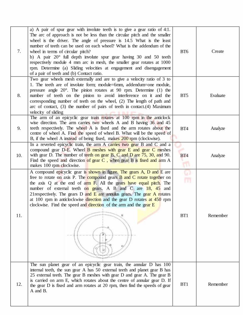
11.
A compound epicyclic gear is shown in figure. The gears A, D and E are free to rotate on axis P. The compound gears B and C rotate together on
the axis Q at the end of arm F. All the gears have equal pitch. The number of external teeth on gears, A B and C are 18, 45 and
21respectively. The gears D and E are annulus gears. The gear A rotates at 100 rpm in anticlockwise direction and the gear D rotates at 450 rpm clockwise. Find the speed and direction of the arm and the gear E
BT1 Remember
12.
The sun planet gear of an epicyclic gear train, the annular D has 100 internal teeth, the sun gear A has 50 external teeth and planet gear B has 25 external teeth. The gear B meshes with gear D and gear A. The gear B is carried on arm E, which rotates about the centre of annular gear D. If the gear D is fixed and arm rotates at 20 rpm, then find the speeds of gear A and B.
BT1 Remember
13.
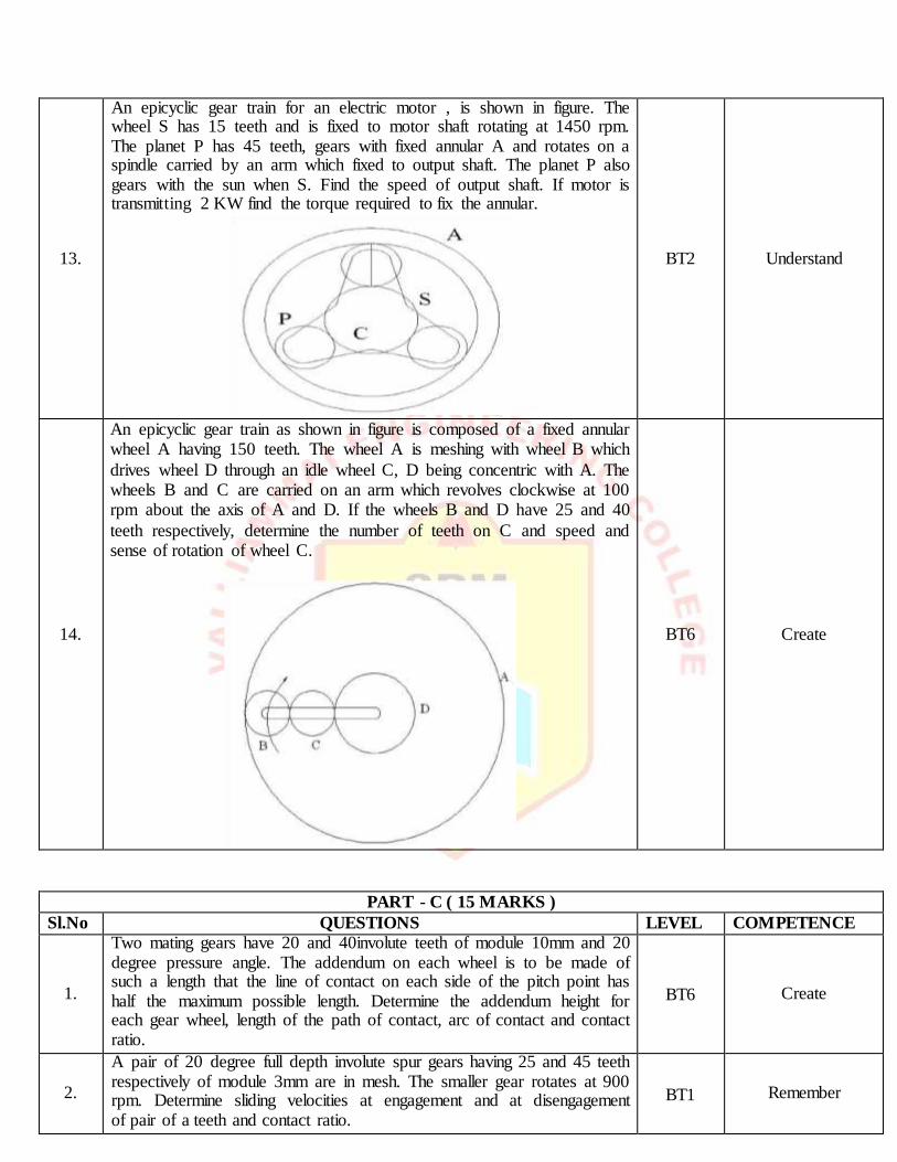
An epicyclic gear train for an electric motor , is shown in figure. The wheel S has 15 teeth and is fixed to motor shaft rotating at 1450 rpm. The planet P has 45 teeth, gears with fixed annular A and rotates on a spindle carried by an arm which fixed to output shaft. The planet P also gears with the sun when S. Find the speed of output shaft. If motor is transmitting 2 KW find the torque required to fix the annular.
BT2 Understand
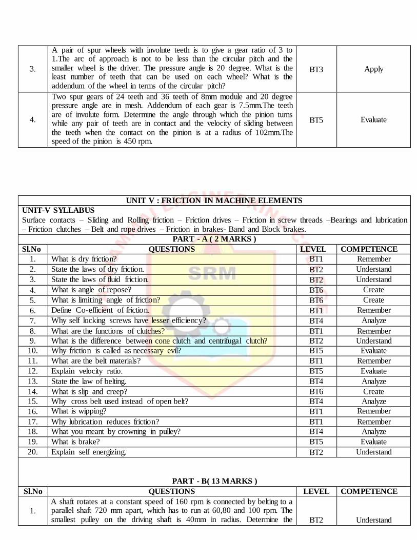
14.
An epicyclic gear train as shown in figure is composed of a fixed annular wheel A having 150 teeth. The wheel A is meshing with wheel B which
drives wheel D through an idle wheel C, D being concentric with A. The wheels B and C are carried on an arm which revolves clockwise at 100 rpm about the axis of A and D. If the wheels B and D have 25 and 40
teeth respectively, determine the number of teeth on C and speed and sense of rotation of wheel C.
BT6 Create
PART - C ( 15 MARKS )
Sl.No QUESTIONS LEVEL COMPETENCE
1.
Two mating gears have 20 and 40involute teeth of module 10mm and 20 degree pressure angle. The addendum on each wheel is to be made of such a length that the line of contact on each side of the pitch point has half the maximum possible length. Determine the addendum height for each gear wheel, length of the path of contact, arc of contact and contact ratio.
BT6 Create
2.
A pair of 20 degree full depth involute spur gears having 25 and 45 teeth respectively of module 3mm are in mesh. The smaller gear rotates at 900 rpm. Determine sliding velocities at engagement and at disengagement of pair of a teeth and contact ratio.
BT1 Remember
3.
A pair of spur wheels with involute teeth is to give a gear ratio of 3 to 1.The arc of approach is not to be less than the circular pitch and the smaller wheel is the driver. The pressure angle is 20 degree. What is the least number of teeth that can be used on each wheel? What is the addendum of the wheel in terms of the circular pitch?
BT3 Apply
4.
Two spur gears of 24 teeth and 36 teeth of 8mm module and 20 degree pressure angle are in mesh. Addendum of each gear is 7.5mm.The teeth are of involute form. Determine the angle through which the pinion turns while any pair of teeth are in contact and the velocity of sliding between the teeth when the contact on the pinion is at a radius of 102mm.The speed of the pinion is 450 rpm.
BT5 Evaluate
UNIT V : FRICTION IN MACHINE ELEMENTS
UNIT-V SYLLABUS
Surface contacts – Sliding and Rolling friction – Friction drives – Friction in screw threads –Bearings and lubrication – Friction clutches – Belt and rope drives – Friction in brakes- Band and Block brakes.
PART - A ( 2 MARKS )
Sl.No QUESTIONS LEVEL COMPETENCE
1. What is dry friction? BT1 Remember
2. State the laws of dry friction. BT2 Understand
3. State the laws of fluid friction. BT2 Understand
4. What is angle of repose? BT6 Create
5. What is limiting angle of friction? BT6 Create
6. Define Co-efficient of friction. BT1 Remember
7. Why self locking screws have lesser efficiency? BT4 Analyze
8. What are the functions of clutches? BT1 Remember
9. What is the difference between cone clutch and centrifugal clutch? BT2 Understand
10. Why friction is called as necessary evil? BT5 Evaluate
11. What are the belt materials? BT1 Remember
12. Explain velocity ratio. BT5 Evaluate
13. State the law of belting. BT4 Analyze
14. What is slip and creep? BT6 Create
15. Why cross belt used instead of open belt? BT4 Analyze
18. What you meant by crowning in pulley? BT4 Analyze
19. What is brake? BT5 Evaluate
20. Explain self energizing. BT2 Understand
PART - B( 13 MARKS )
Sl.No QUESTIONS LEVEL COMPETENCE
1. A shaft rotates at a constant speed of 160 rpm is connected by belting to a parallel shaft 720 mm apart, which has to run at 60,80 and 100 rpm. The smallest pulley on the driving shaft is 40mm in radius. Determine the
BT2
Understand
remaining radii of the two stepped pulleys for a crossed belt and an open belt. Neglect belt thickness and slip.
2.
A shaft rotating at 200 rpm drives another shaft at 300 rpm and transmits 6 kw through a belt. The belt is 100 mm wide and 10mm thick. The distance between the shafts is 4m.The smaller pulley is 0.5m in diameter. Calculate the stress in the belt, if it is an open belt drive and a cross
belt drive. Take µ=0.3.
BT3 Apply
3.
The leather belt is required to transmit 6.5kW from a pulley 1.0m in diameter running at 300 rpm. The angle embraced is 155 degree and the
co-efficient of friction between the belt and the pulley is 0.2.If the safe working stress for the leather belt is 1.3 MPa, density of leather 1.3 Mg/m3 and thickness of the belt 13mm,determine the width of the belt
taking centrifugal tension into account.
BT1 Remember
4.
An open flat belt drive connects two parallel shafts 1.2 m apart. The driving and driven shafts rotates at 350 rpm and 140 rpm respectively and the driven pulley is 400mm in diameter. The belt is 5mm thick and 80mm wide. The co-efficient of friction between the belt and pulley is 0.3 and the maximum permissible tension in the belting is 1.4MN/m2.Determine the diameter of the driving pulley, maximum power that may be transmitted by the belting and required initial belt
tension.
BT6 Create
5.
a) For a flat belt, prove that T1/T2=eμθ Where T1 and T2= Tension in the tight and slack sides of the belt, _= Angle of contact between the belt and the pulley, and μ= Coefficient of friction between the belt and the pulley.
b) An open belt running over two pulley of 1.5 m and 1.0 m diameters connects two parallel shafts 4.8 m apart. The initial ten in the belt is 3000 N. The smaller pulley is rotating at 600 rpm. The mass of belt is 0.6703 kg/m length. The coefficient of friction between the belt and pulleys is 0.3. Find (1) the exact length of the belt required (2) the power transmitted taking centrifugal tension into account.
BT1 Remember
6.
a) A multi plate disc clutch transmits 55 kW of power at 1800 rpm. Coefficient of friction for the friction surfaces is 0.1. Axial intensity at pressure is not to exceed 160 kN/m2. The internal radius is 80 mm and is 0.7 times the external radius. Find the number of plates needed to transmit the required torque.
b) A rope drive is required to transmit 230 kW from a pulley of 1m diameter running at 450 rpm. The safe pull in each rope is 800 N and the mass of the rope is 0.4 kg per meter length. The angle of lap and groove angle 1600 and 450 respectively. If coefficient of friction is 0.3, find the number of ropes required.
BT4 Analyze
7.
The mean diameter of the screw jack having pitch of 10 mm is 50 mm. A load of 20 KN is lifted through a distance of 170 mm. Find the work done in lifting the load and efficiency of the screw jack when (i) the load rotates with the screw, and (ii) the load rests n the loose head which does not rotate with screw. The external and internal diameter of the bearing surface of the loose head is 60mm and 10mm respectively. The coefficient of friction for the screw as well as the bearing surface may be taken as 0.08
BT5 Evaluate
8.
a).A leather belt is required to transmit 7.5 kW from a pulley 1.2 m in diameter, running at 250 rpm. The angle entranced is 165° and the coefficient of friction between the belt and the pulley is 0.3. If safe working stress for the leather belt is 1.5 MPa, density of leather is 1 kg/m3 and thickness of belt is 10 mm. Determine the width of the belt taking Centrifugal tension into account.
b)Two pulley one 450 mm diameter and other 200mm diameter are on parallel shaft 2.1 m apart and are connected by a cross belt. The larger pulley rotates at 225 rpm. The maximum permissible tension in the belt is 1 kN and the coefficient of friction between the belt and the pulley is 0.25. Find the length of the belt required and the power can be transmitted.
BT1
Remember
9.
a) Prove or disprove the following statement – “Angle of friction is equal to angle of repose”
b) Briefly explain the following: 1) Slip of the belt 2) Creep of the belt.
BT4 Analyze
10.
A conical pivot bearing supports a vertical shaft of 200mm diameter. It is subjected to a load of 30kN. The angle of cone is 1200 and the co-efficient of friction is 0.025. Find the power lost in friction when the speed is 140 rpm assuming i) Uniform pressure and ii) Uniform wear.
BT3 Apply
11.
A single plate clutch is required to transmit 8 kW at 1000 rpm. The axis pressure is limited to 70 kN/m2. The mean radius of the plate is 4.5 times the radial width of the friction surface. If both the sides of the plate are
effective and the coefficient of friction is 0.25. Find a) the inner and the outer radius of the plate and the mean radius, b) the width of the friction
lining.
BT1 Remember
12.
A shaft has a number of collars integral with it. The external diameter of the collars is 400mm and the shaft diameter is 250 mm. If the uniform intensity of pressure is 0.35N/mm2 and its coefficient of friction is 0.05, estimate i) power absorbed in overcoming friction when the shaft runs at 105 rpm and carries a load of 150KN and ii) number of collars required.
BT5 Evaluate
13.
a) Derive an expression for braking torque on the drum of simple band brake.
b.) Deduce the expression for the friction moment of a collar thrust
bearing, stating clearly the assumption made.
BT2 Understand
14.
Two shaft whose centers are 1m apart are connected by a V belt drive. The driving pulley is supplied with 100 kW and has an effective diameter
of 300 mm. It runs at 375 rpm. The angle of groove on the pulley is 400 The permissible tension in 400 mm2 cross sectional area of the belt is 2.1 MPa. The density of the belt is 1100 kg/ mm3 coefficient of friction is
0.28. Estimate number of belts required
BT6 Create
PART - C ( 15 MARKS )
Sl.No QUESTIONS LEVEL COMPETENCE
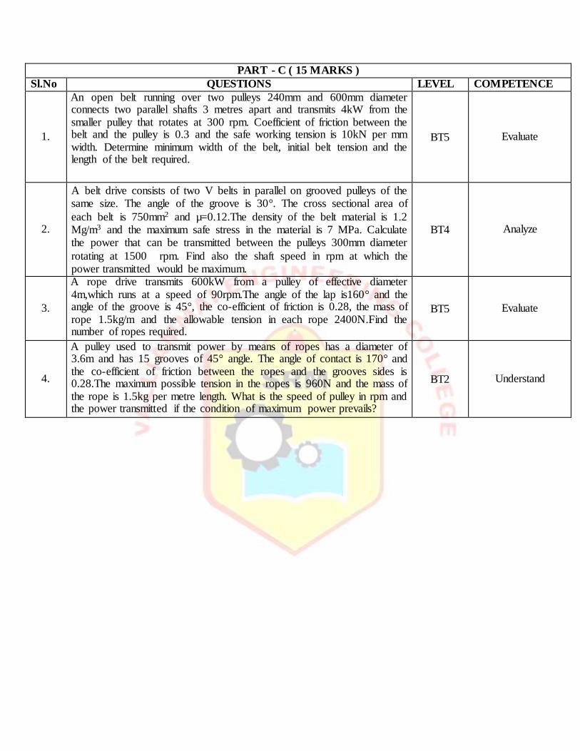
1.
An open belt running over two pulleys 240mm and 600mm diameter connects two parallel shafts 3 metres apart and transmits 4kW from the smaller pulley that rotates at 300 rpm. Coefficient of friction between the belt and the pulley is 0.3 and the safe working tension is 10kN per mm width. Determine minimum width of the belt, initial belt tension and the length of the belt required.
BT5 Evaluate
2.
A belt drive consists of two V belts in parallel on grooved pulleys of the same size. The angle of the groove is 30°. The cross sectional area of
each belt is 750mm2 and µ=0.12.The density of the belt material is 1.2 Mg/m3 and the maximum safe stress in the material is 7 MPa. Calculate the power that can be transmitted between the pulleys 300mm diameter
rotating at 1500 rpm. Find also the shaft speed in rpm at which the power transmitted would be maximum.
BT4 Analyze
3.
A rope drive transmits 600kW from a pulley of effective diameter 4m,which runs at a speed of 90rpm.The angle of the lap is160° and the angle of the groove is 45°, the co-efficient of friction is 0.28, the mass of rope 1.5kg/m and the allowable tension in each rope 2400N.Find the number of ropes required.
BT5 Evaluate
4.
A pulley used to transmit power by means of ropes has a diameter of 3.6m and has 15 grooves of 45° angle. The angle of contact is 170° and the co-efficient of friction between the ropes and the grooves sides is 0.28.The maximum possible tension in the ropes is 960N and the mass of the rope is 1.5kg per metre length. What is the speed of pulley in rpm and the power transmitted if the condition of maximum power prevails?