Prepared by Mr. S.SURESH BABU Mr. SATTAINATHAN SHARMA.A Mr. R.KARTHICK VALLIAMMAI ENGINEERING COLLEGE SRM Nagar, Kattankulathur – 603 203 DEPARTMENT OF CIVIL ENGINEERING QUESTION BANK VI SEMESTER CE6603 – DESIGN OF STEEL STRUCTURES Regulation – 2013 Academic Year 2018 – 19 Prepared by Mr. S.SURESH BABU, Assistant Professor/CIVIL Mr.SATTAINATHAN SHARMA.A, Assistant Professor/CIVIL Mr.R.KARTHICK, Assistant Professor/CIVIL STUDENTSFOCUS.COM
Transcript
Prepared by Mr. S.SURESH BABU Mr. SATTAINATHAN SHARMA.A Mr. R.KARTHICK
3. Determine the tensile strength of a roof truss member 2 ISA
90x60x6 mm connected to the gusset plate of 8 mm thickness by
4mm weld. The effective length of weld is 200mm.
BT-3
Apply
4. Design a tension member to carry a factored force of 340KN. Use
20mm diameter black bolts and a gusset plate of 8mm thick.
BT-1 Remember
5. Design a single angle equal section 100x100x10 mm, connected to
a gusset plate at the ends with 20mm diameter bolts with the
connection length of 250mm to transfer tension.
BT-1 Remember
6. Write the procedure for the design of tension members BT-4 Analyse
7. Explain in detail about the modes of failure in Tension member. BT-1 Remember
8. Find the suitable dimensions so as to design a tension member
using 2 unequal angles of size 120mm x 90mm x 8mm with a
10mm thick gusset plate. The short leg is outstanding. The pull on
the member of 250kN
BT-4
Analyse
9. Explain the concept of shear lag in detail BT-2 Understand
10. Discuss in detail about Tension member splice BT-5 Evaluate
11. Find the suitable design for a single angle section for a tension
member of a roof truss to carry a factored tensile force of 225KN.
The member is subjected to the possible reversal of stress due to the
action of wind. The length of the member is 3m.use 20mm shop
bolts of grade4.6 for the connection.
BT-2
Understand
12. Design as bridge truss diagonal subjected to a factored tensile load
of 300 kN. The length of the diagonal is 3.0m. the tension member
is connected to a gusset plate of 16mm thick with one line of 20mm
diameter bolts of grade 8.8
BT-6
Create
13. Determine the tensile capacity of the sections
a) Angles are placed on the opposite side of gusset plates
b) Angles are placed on the same side of gusset plates
BT-3
Apply
14. Illustrate lug angle with neat sketch and give its uses also BT-4 Analyse
Q.NO PART-C BT
Level
Competence
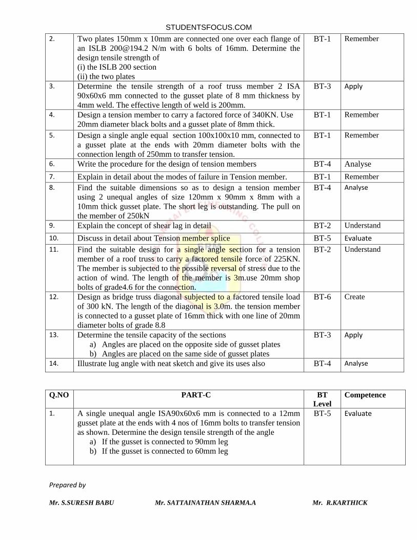
1. A single unequal angle ISA90x60x6 mm is connected to a 12mm
gusset plate at the ends with 4 nos of 16mm bolts to transfer tension
as shown. Determine the design tensile strength of the angle
a) If the gusset is connected to 90mm leg
b) If the gusset is connected to 60mm leg
BT-5
Evaluate
STUDENTSFOCUS.COM
Prepared by Mr. S.SURESH BABU Mr. SATTAINATHAN SHARMA.A Mr. R.KARTHICK
2. Identify the suitable design for a tension splice for a tension
member sections 160mm x 10mm and 250mm x 12 mm. The
member is subjected to a pull of 200 KN.
BT-5
Evaluate
3. A tension member of a truss consists of a single channel ISLC
[email protected]/m and is subjected to a factored tension of 300kN.
Design the connection of the member to a gusset plate using lug
angles. Provide welded connection.
BT-3
Apply
4. A tension member of a roof truss carries a factored axial tension of
430kN. Design the section and the connection
a) Without using lug angles
b) Using lug angles
BT-3
Apply
UNIT III - COMPRESSION MEMBERS Types of compression members – Theory of columns – Basis of current codal provision for compression
member design – Slenderness ratio – Design of single section and compound section compression
members – Design of laced and battened type columns – Design of column bases – Gusseted base
Q.NO PART-A BT level Competence
1. Define compression member. BT-1 Remember
2. List the various types of compression members? BT-1 Remember
3. Distinguish column and strut BT-2 Understand
4. Define effective length of a column. BT-1 Remember
5. State the uses of providing column base? BT-1 Remember
6. Design the various column connections with different sections. BT-6 Create
7. Evaluate the effective length of column based on end conditions BT-5 Evaluate
8. What do you mean by web buckling? BT-1 Remember
9. Discuss the purpose of providing battens in compound steel columns?
BT-2 Understand
STUDENTSFOCUS.COM
Prepared by Mr. S.SURESH BABU Mr. SATTAINATHAN SHARMA.A Mr. R.KARTHICK
10. Distinguish slab base and gusseted base. BT-2 Understand
11. Classify the modes of failure in compression member. BT-3 Apply
12. Define buckling load and state the assumptions made in Euler’s
analysis
BT-1 Remember
13. Illustrate the lateral systems that are used in compound columns. BT-4 Analyse
14. Analyze slenderness ratio and its importance. BT-4 Analyse
15. Differentiate between slab base and gusseted base for steel columns
BT-2 Understand
16. Examine the cause for decrease in permissible stresses due toincrease in slenderness ratio
BT-4 Analyse
17. Why lacings are used in compression members? BT-3 Apply
18. Justify the purpose for providing anchors bolt in base plate? BT-5 Evaluate
19. Discuss about column splices and its types. BT-6 Create
20. Relate local buckling with torsional buckling. BT-3 Apply
Q.NO PART-B
BT
Level
Competence
1. A rolled steel beam section HB 350 @ 0.674 kN/m is used as a
stanchion. If the unsupported length of the stanchion is 4 m,
evaluate safe load carrying capacity of the section.
BT-5 Evaluate
2. Find the suitable design for a built-up column consisting of
two channels connected by batten to carry an axial load of 800 KN;
the effective length of the column is 6 m.
BT-1 Remember
3. Explain the step by step procedure for finding the load
carrying capacity of a compression member. BT-2 Understand
4. Determine the design axial load on the column section ISMB 400,
given that the height of the column is 3.5 m and that it is pin-ended.
Also assume the following: 𝑓𝑦= 250 N/mm2, 𝑓𝑢=410 N/mm
2; E =
2×10⁵ N/mm
2
BT-3 Apply
5. i) List out the maximum values of effective slenderness ratio for
various members as per IS recommendations. (7)
ii) Analyse the different failure modes of column in detail (6)
BT-4 Analyse
6. Design a column using a rolled steel l-section with cover plates to
carry a factored axial load of 2000kN. The effective length in both
the planes is 5m. Take fy = 250 MPa and E= 200 GPa
BT-1 Remember
7. Illustrate in detail about column splice and mention its purpose BT-3 Apply
8. A column of ISMB 400 is subjected to an axial force of 750kN.
Analyse and design suitable base plate. Assume necessary data
required.
BT-4 Analyse
9. Calculate the compressive resistance of a compound column
consisting ISMB 500 with one cover plate 350 x 20 mm on each BT-1 Remember
STUDENTSFOCUS.COM
Prepared by Mr. S.SURESH BABU Mr. SATTAINATHAN SHARMA.A Mr. R.KARTHICK
flange and having a length of 5 m. Assume that the bottom of
column is fixed and top is rotation fixed, translation free. 10. A built up column consists ISHB 400@ 77.40 kg/m with one
300mm x 12mmflange plate on each side. The column carries an axial load of 2600kN. Determine the suitable dimension for a gusseted base, if the column is supported on concrete pedestal with a bearing pressure of 5N/mm
2.
BT-1 Remember
11. Describe about laced column and also explain its design and specifications. BT-2 Understand
12. Design a column with single lacing system to carry a factored axial load of 1500kN. The effective height of the column is 4.2m. Use two channels placed toe to toe.
BT-2 Understand
13. A discontinuous strut of length 4 m consists of two unequal angles ISA 100×75×8 and is connected to a 10 mm thick gusset plate by its longer leg. Determine the strength if it is connected on the: i) Opposite side of the gusset plate ii) Same side of the gusset plate
BT-4 Analyse
14. Design a suitable slab base for a column section ISHB 400@ 822
N/m. Supporting an axial load 500kN. The base plate is to rest on
a concrete pedestal of M20 grade concrete.
BT-6 Create
Q.NO PART-C BT
Level
Competence
1. A batten column of 10-m long is carrying a factored load of 1150 kN. The column is restrained in position but not in direction at both ends. Design a built up column using channel sections placed back to back.
BT-1 Remember
2. A built up column consists of ISHB 400 @ 77.4 kg/m with one 300 mm x 12 mm flange plate on each side. The column carries an axial load of 2600 kN. Design a gusseted base if the column is supported on concrete pedestal with a bearing pressure of 5 N/ mm
2.
BT-4 Analyse
3. Find the suitable design for a laced column for an axial load of 1200kN with an effective span of 7.5m has one end fixed and other end hinged. Use channels for main members and an angle for lacing
BT-2 Understand
4. A steel column ISHB 400 @ 759.3 N/m is subjected to a factored axial load of 2000 kN. Design a slab base plate for the column. Assume that the bearing surfaces of the column and base plate are machined and the concrete footing is of M20 grade.
BT-3 Apply
STUDENTSFOCUS.COM
Prepared by Mr. S.SURESH BABU Mr. SATTAINATHAN SHARMA.A Mr. R.KARTHICK
UNIT IV - BEAMS
Design of laterally supported and unsupported beams – Built up beams – Beams subjected to uniaxial
and biaxial bending – Design of plate girders - Intermediate and bearing stiffeners – Flange and web
splices.
Q.NO PART-A BT level Competence
1. Define shape factor and what is meant by slender section? BT-1 Remember
2. Write the various factors affecting the lateral-torsional buckling strength BT-6 Create
3. What is laterally unsupported beam? Give an example. BT-1 Remember 4. Demonstrate the reasons behind splicing in plate girder BT-3 Apply 5. Evaluate the economical depth of a plate girder? BT-5 Evaluate 6. Write about the Box girders. BT-3 Apply 7. Construct the failure mode of laterally unsupported beams BT-6 Create 8. What do you mean by castellated beam? BT-1 Remember 9. Explain effective sectional area in column design BT-4 Analyse 10. Write the formula for calculating the thickness of beam bearing
plate BT-3 Apply 11. Discuss about built up beams BT-2 Understand 12. Distinguish web buckling and web crippling? BT-4 Analyse 13. What are the classifications in Stiffeners? BT-1 Remember 14. Examine the shear resistance of steel beams BT-4 Analyse 15. Define laterally restrained beam. Why do compression flanges
require lateral support? BT-1 Remember 16. What do you mean by curtailment of flanges? BT-2 Understand 17. Justify the purpose for providing the bearing stiffener and where it
is used? BT-5 Evaluate 18. List the design consideration in design of steel beams. BT-2 Understand 19. What is web crippling? BT-1 Remember 20. Discuss the elements of the plate girder. BT-2 Understand
Q.NO PART-B
BT
Level
Competence
1. An ISMB 500 section IA used as a beam over a span of 6 m, with simply supported ends. Determine the maximum factored
uniformly distributed load that the beam can carry if the ends are
restrained against torsion but compression flange is laterally
unsupported. BT-5 Evaluate 2. Find the suitable design for a simply supported steel joist with a
4.0m effective span carries a UDL of 40kN/mover its span
inclusiveof self-weight. The beam is laterally unsupported.
BT-1 Remember
STUDENTSFOCUS.COM
Prepared by Mr. S.SURESH BABU Mr. SATTAINATHAN SHARMA.A Mr. R.KARTHICK
3. Find the suitable design for a simply supported beam of effective
span 10m carrying a factored load of 30kN/m. The compression
flange of the beam is laterally restrained all along and provided
with stiffened end bearing of 100mm wide. The overall depth of
the beam is restricted to 450mm.
BT-1 Remember
4. Estimate the suitable built up beam section for a span of 8m to
carry a uniformly distributed load of 15kN/m and a central
concentrated load of 100 kN. The beams is laterally supported
through out.Show the curtailment of plates also
BT-2 Understand
5. Write short notes on the design of laterally unsupported beam. BT-1 Remember
6. A welded plate girder of span 25m is laterally restrained
throughout its length. It has to carry a load of 80 kN/m over the
whole span besides its weight. Design the girder without
intermediate transverse stiffeners.
BT-6 Create
7. Explain the step by step procedure for design of vertical, intermediate and horizontal stiffeners in a plate girder.
BT-2 Understand
8. A cantilever beam of length 4.5 m supports a dead load (including self weight) of 18 kN/m and a live load of 12 kN/m. Assume a bearing length of 100 mm. Analyze and Design the beam.
BT-4 Analyse
9. A welded plate girder has
i) Each top and bottom flange = 435 x 28 mm and
ii) Web 1250 x 10 mm. Predict the design of vertical and
horizontal stiffeners.
BT-2 Understand
10. Design a bearing stiffener for a welded plate girder with the
following specifications.
Web = 1000mm X 6mm thick.
Flanges = 2 Nos. of 350X20mmplate on each side.
Support reaction = 350kN.Width of the support = 300mm.
BT-4 Analyse
11. Check the beam section WB 500 @1.45 kN/m against web
crippling and web buckling if reaction at the end of beam is 179.6
kN, The length of bearing plate at the support is 120 mm. Design
bearing plate. The bearing plate is set in masonry
BT-1 Remember
12. Analyze and Design a laterally supported beam of effective span 5 m for the following data. Grade of steel: Fe 410 Factored maximum B.M. = 180 kN-m Factored maximum S. F. = 220 kN Check for deflection is not required
BT-4 Analyse
13. A simply supported beam of span 3.25m consists of rolled steel section ISLB 325 @ 422.8 N/m. Determine the design bending strength of the beam, if the beam is laterally unsupported.
BT-3 Apply
14. Show the design of web and flanges for a reverted plate girder is
simply supported over an effective span of 16m. It carries a UDL
of 80kN/m in addition to its self weight. And two points of 400kN
each at 4m from their supports.
BT-3 Apply
STUDENTSFOCUS.COM
Prepared by Mr. S.SURESH BABU Mr. SATTAINATHAN SHARMA.A Mr. R.KARTHICK
Q.NO PART-C BT
Level
Competence
1. Calculate the design bending strength of ISLB 300 @ 0.369 kN/m considering the beam to be (a)Laterally supported (b)Laterally unsupported Assume the design force is less the design shear strength and is of low shear. The effective length of the beam (LLT) is 4 m. Assume Fe410 grade of steel.
BT-2 Understand
2. A simply supported steel joist of 4 m effective span is laterally supported throughout. It carries a total udl of 40 kN (service load inclusive of self weight). Design an appropriate section using steel of grade Fe 410.
BT-3 Apply
3. Design a simply supported steel joist of 5 m effective span, carrying a uniformly distributed load 12 kN/m if compression flange of the joist is laterally unrestrained.
BT-4 Analyse
4. Design rolled steel I section for a simply supported beam with a clear span of 6 m. It carries a UDL 50 kN/m excluding self weight of the girder. The beam is laterally supported.
BT-3 Apply
UNIT V- ROOF TRUSSES AND INDUSTRIAL STRUCTURES
Roof trusses – Roof and side coverings – Design of purlin and elements of truss; end bearing – Design of
gantry girder.
Q.NO PART – A BT
Level
Competence
1. Explain the co efficient of external wind pressure. BT-2 Understand
2. Calculate the design wind speed BT-4 Analyse
3. Write the uses of sag rod in a roof truss BT-3 Apply
4. Explain about the importance of steel decking. BT-2 Understand
5. State the necessity of curtailment of flange plates in plate girder. BT-4 Analyse
6. What is the purpose of the purlin in a roof truss? BT-5 Evaluate
7. What are the loads to be considered for the design of gantry girder? BT-4 Analyse
8. List the criteria to be adopted for arriving at the spacing of truss? BT-5 Evaluate
9. List the various components of a roof truss. BT-3 Apply
10. Classify the type of truss based on span. BT-3 Apply
11. Define bracing and Why bracings required in roof trusses? BT-1 Remember
12. Define drag force. BT-1 Remember
STUDENTSFOCUS.COM
Prepared by Mr. S.SURESH BABU Mr. SATTAINATHAN SHARMA.A Mr. R.KARTHICK
13. Define pitch of trusses BT-1 Remember
14. Evaluate why impact factor is considered in the computation of
loads acting on gantry girder?
BT-2 Understand
15. Define gantry girders BT-1 Remember
16. Which section is recommended for gantry girder?why BT-6 Create
17. Define Drift Analysis BT-1 Remember
18. Explain recommended allowable stresses and deflection for gantry
girder?
BT-6 Create
19. Name the commonly used roof coverings. BT-2 Understand
20. Define end bearing in roof trusses? BT-1 Remember
Q.NO PART – B BT
Level
Competence
1. i.Classify the different types of roof truss with neat sketches (7)
ii.Give general guidelines for fixing spacing of roof trusses (6)
BT-2 Understand
2. A roof truss- shed is to be built Jodhpur city area for an industrial
use. Determine the basic wind pressure .The use of shed 18 m x 30 m
BT-1 Remember
3.
An industrial roof shed of size 20 mx30 m is proposed to be
constructed at Mangalore near a hillock of 160 m and slope is 1 in
2.8. The roof shed is to be built at a height of 120 m from the base of
the hill. Determine the design wind pressure on the slope. The height
of roof shed shall be 12m
BT-1 Remember
4.
A communications tower of 80 m height is proposed to be built hill
top height 520 m with a gradient of 1in 5. The horizontal approach
distance is 2.8 m km from the level ground .The tower is proposed at
Abu mount .Determine the design wind pressure.
BT-1 Remember
5.
Design a purlin for a roof truss having the following data:
Span of the truss = 6.0m ,Spacing of truss = 3m c/c, Inclination of


![INDEX [studentsfocus.com]studentsfocus.com/notes/anna_university/IT/4SEM... · cs6412 – microprocessor and microcontroller lab dept of cse 2 expt.no name of the experiment page](https://static.documents.pub/doc/80x56/5afd184c7f8b9a323491255e/index-microprocessor-and-microcontroller-lab-dept-of-cse-2-exptno-name.jpg)


