SUFFIX I SUFFIX II SUFFIX III Code Seat/Disc/Etc. Material Code Form of Flow Code Feature E EPDM (Ethylene Propylene) † F Normally Closed † HW Hot Water Construction J CR (Neoprene) † G Normally Open † LT Low Temperature † K Air Operated, 3-30 psi † U Universal M Metering Device N Oxygen † MB Mounting Bracket † Q Long-Life Construction MO Manual Operator † R Resilient MS Screw Type Manual Operator T PTFE (Teflon*) † VH High Vacuum V FPM (Viton*) † VM Medium Vacuum † Covered on the pages of the Series in which it is used. * DuPont Co. trademark. EF HT 8210 G 2 V MO Explosionproof Enclosure Class H High-Temperature Coil Series Number Design Change Letter ➀ Size FKM Elastomer Manual Operator ➀ The Design Change Letter indicates a major design change affecting spare parts kits, rebuild kits, and coils. The correct replacement parts for each change letter are shown in ASCO’s Rebuild Kits and Coils Catalog. How to Select and Specify Not all optional features are appropriate or available for all valves. Table 1 lists the optional electrical feature prefixes available for each Red-Hat II ® solenoid and coil. Specify these features by adding the indicated prefixes to the valve catalog number. For those prefixes marked with a “ • ” or for optional Red-Hat ® electrical features not covered here, contact your local ASCO sales office. Table 2 lists the suffixes for optional construction features available for each valve Series. Specify these features by adding the indicated suffixes to the valve catalog number. Optional Features 4 10.01 Table 2: Suffixes for Optional Construction Features Table 1: Optional Red-Hat II ® Electrical Feature Prefixes (For Red-Hat ® optional electrical features, contact your local sales office.) Note: See chart on page 10.02 for specific power and temperature ratings. Code Solenoid EF Type 7 Explosionproof EV Type 7 Explosionproof with 316 Stainless Steel Hub and Stainless Steel Base Plate GP Panel Mount Type 1 General Purpose Solenoid J Junction Box JP Panel Mount Junction Box OF Open Frame Spade and Screw Terminal Solenoids OP Panel Mount Spade, Screw and DIN Terminal Solenoids Code Coil HB Class H - Intermediate Power ● HC Class H - Battery Charging Coil HT Class H - High Temperature KB Class H - Intermediate Power - Screw Terminals ● KC Class H - Battery Charging Circuit - Screw Terminals KF Class F - High Temperature - Screw Terminals KH Class H - High Temperature - Screw Terminals KP Class F - Intermediate Power - Screw Terminals SC Class F - High Temperature - DIN Connection SD Class F - Intermediate Power - DIN Connection SF Class F - High Temperature - Spade Terminals SP Class F - Intermediate Power - Spade Terminals SS Class H - Intermediate Power - Spade Terminals ST Class H - High Temperature - Spade Terminals SU Class H - High Temperature - DIN Connection SV Class H - Intermediate Power - DIN Connection ● SW Class H - Battery Charging Circuit - Spade Terminals Code Feature ● L 72" continuous leads ● X Other special constructions Electrical Features Basic Valve Catalog Number Construction Features An example of an ASCO valve catalog number with prefixes and suffixes:
Transcript
SUFFIX I SUFFIX II SUFFIX IIICode Seat/Disc/Etc. Material Code Form of Flow Code Feature
E EPDM (Ethylene Propylene) † F Normally Closed † HW Hot Water ConstructionJ CR (Neoprene) † G Normally Open † LT Low Temperature
† K Air Operated, 3-30 psi † U Universal M Metering DeviceN Oxygen † MB Mounting Bracket
† Q Long-Life Construction MO Manual Operator† R Resilient MS Screw Type Manual
OperatorT PTFE (Teflon*) † VH High VacuumV FPM (Viton*) † VM Medium Vacuum
† Covered on the pages of the Series in which it is used.* DuPont Co. trademark.
EF HT 8210 G 2 V MOExplosionproof EnclosureClass H High-Temperature CoilSeries NumberDesign Change Letter ➀
SizeFKM Elastomer
Manual Operator
➀ The Design Change Letter indicates a major design change affecting spare parts kits, rebuild kits, andcoils. The correct replacement parts for each change letter are shown in ASCO’s Rebuild Kits andCoils Catalog.
How to Select and Specify
Not all optional features are appropriate or available for all valves.
Table 1 lists the optional electrical feature prefixes available foreach Red-Hat II® solenoid and coil. Specify these features by addingthe indicated prefixes to the valve catalog number.
For those prefixes marked with a “•” or for optional Red-Hat®
electrical features not covered here, contact your local ASCO sales office.
Table 2 lists the suffixes for optional construction features available foreach valve Series. Specify these features by adding the indicatedsuffixes to the valve catalog number.
Optional Features4
10.01
Table 2: Suffixes for Optional Construction Features
Note: See chart on page 10.02 for specific power and temperature ratings.
Code SolenoidEF Type 7 ExplosionproofEV Type 7 Explosionproof with 316 Stainless Steel Hub and
Stainless Steel Base PlateGP Panel Mount Type 1 General Purpose SolenoidJ Junction BoxJP Panel Mount Junction BoxOF Open Frame Spade and Screw Terminal SolenoidsOP Panel Mount Spade, Screw and DIN Terminal Solenoids
Code CoilHB Class H - Intermediate Power
● HC Class H - Battery Charging CoilHT Class H - High TemperatureKB Class H - Intermediate Power - Screw Terminals
● KC Class H - Battery Charging Circuit - Screw TerminalsKF Class F - High Temperature - Screw TerminalsKH Class H - High Temperature - Screw TerminalsKP Class F - Intermediate Power - Screw TerminalsSC Class F - High Temperature - DIN ConnectionSD Class F - Intermediate Power - DIN ConnectionSF Class F - High Temperature - Spade TerminalsSP Class F - Intermediate Power - Spade TerminalsSS Class H - Intermediate Power - Spade TerminalsST Class H - High Temperature - Spade TerminalsSU Class H - High Temperature - DIN ConnectionSV Class H - Intermediate Power - DIN Connection
● SW Class H - Battery Charging Circuit - Spade Terminals
Code Feature● L 72" continuous leads● X Other special constructions
Elec
trica
l Fea
ture
s
Basic
Valve
Cata
log
Num
ber
Cons
truct
ion
Feat
ures
An example of an ASCO valve catalog number withprefixes and suffixes:
Optional Features4Electrical
Optional Electrical FeaturesMost optional electrical features shown here can be included onASCO valves approved by UL, FM, and CSA.
Identify the options you want by adding the appropriate prefix tothe catalog number of the valve you are specifying.
To determine the proper prefix, use the Valve Series SpecificationTable for the valve you are ordering to determine its watt rating/class of coil insulation.
Red-Hat II Solenoid OptionsUsing Table 3, find the desired solenoid option in the left columnand the watt rating/class of coil insulation in the next column. Thechoice of prefixes is shown in the next two columns on that line.The first column indicates the prefix if Class F temperatureprotection is sufficient for your requirements. The second columnprovides the desired solenoid option, plus the higher temperatureprotection of a Class H coil.
For example, to select an 8262G2 valve with a Class H Open FrameSpade Terminal Solenoid, assuming the voltage to be 120 volts AC,60 Hz:
• In the Specification Table for Series 8262, the Watt Rating/Classof Coil Insulation is 6.1/F for Catalog Number 8262G2.
• Using Table 3, find the listing for “Open Frame Solenoid withSpade Terminal Coil” in the left column. Then, find 6.1/F underAC coils in the next column. Reading across the column headed“Class H Coil,” you’ll find the prefix “OFST.” To order, specifyCatalog Number OFST8262G2, 120/60.
(Note: Always include the voltage and frequency.)
10.02
SolenoidOption
Required
Watt Rating/Class of Insulation
Class F Coil
Prefix
Class HCoil
PrefixAC DCGeneral Purpose
Solenoid (StandardValve Construction)
6.1/F10.1/F
1.4/F10.6/F 11.6/F
——HTHT
9.1/F17.1/F
22.6/F — HB
Panel Mount Type 1
General PurposeSolenoid
6.1/F 10.1/F
10.6/F 11.6/F GP GPHT
9.1/F17.1/F
22.6/F GP GPHB
Type 7 Explosionproof
Solenoid
6.1/F 10.1/F
10.6/F 11.6/F EF EFHT
9.1/F 17.1/F
22.6/F EF EFHB
10.1/F15.1/F 17.1/F
1.4/F11.6/F22.6/F
EV—
EVHTEVHB
Open Frame Solenoidwith Spade Terminal
Coil
6.1/F 10.1/F
10.6/F11.6/F OFSF OFST
9.1/F17.1/F
22.6/F OFSP OFSS
Panel MountSolenoid with Spade
Terminal Coil
6.1/F10.1/F
10.6/F 11.6/F OPSF OPST
9.1/F17.1/F
22.6/F OPSP OPSS
Open Frame Solenoidwith Screw Terminal
Coil
6.1/F10.1/F
10.6/F11.6/F OFKF OFKH
9.1/F17.1/F
22.6/F OFKP OFKB
Panel MountSolenoid with Screw
Terminal Coil
6.1/F 10.1/F
10.6/F 11.6/F OPKF OPKH
9.1/F 17.1/F
22.6/F OPKP OPKH
Junction Box with Spade Terminal Coil
6.1/F 10.1/F
10.6/F11.6/F JSF JST
9.1/F17.1/F
22.6/F JSP JSS
Panel MountJunction Box with
Spade Terminal Coil
6.1/F 10.1/F
10.6/F 11.6/F JPSF JPST
9.1/F 17.1/F
22.6/F JPSP JPSS
Junction Box with Screw Terminal Coil
6.1/F10.1/F
10.6/F11.6/F JKF JKH
9.1/F17.1/F
22.6/F JKP JKB
Panel MountJunction Box with
Screw Terminal Coil
6.1/F10.1/F
10.6/F11.6/F JPKF JPKH
9.1/F17.1/F
22.6/F JPKP JPKB
DIN ConnectionSolenoid
6.1/F10.1/F
10.6/F11.6/F SC SU
9.1/F17.1/F
22.6/F SD SV
Panel Mount DIN Connection Solenoid
6.1/F10.1/F
10.6/F11.6/F OPSC OPSU
9.1/F17.1/F
22.6/F OPSD OPSV
Table 3: Solenoid Options for Red-Hat II® Valves
Type 1 General Purpose Solenoids with Class F High-Temperature Coils
Enclosures:• Also meet Type 2 Dripproof, Types 3 and 3S Raintight, and Types 4 and 4X Watertight requirements.• Supplied standard with 1/2" threaded conduit hub and built-in strain relief for leads. Coils:• Insulation system for coil temperatures up to 311°F (155°C).➀• For ambient temperature requirement, refer to specific Series and charts in Engineering Information Section, beginning on page 11.00.• Suitable for 50 and 60 Hz.➁
Ordering Information: Supplied standard on all Red-Hat II valves.
Type 1 General Purpose Solenoids with Class H High-Temperature Coils
Enclosures: • Same as Class F. Coils: • Insulation system suitable for coil temperatures up to 356°F (180°C).➀ For ambient temperature requirements, refer to specific Series and charts in Engineering Information Section, page 11.00.• Suitable for 50 and 60 Hz.➁
Ordering Information: Depending on wattage, use catalog numberprefix “HT” or “HB” (e.g., HT8210G2).
Panel Mount Type 1 General Purpose Solenoids with Class F or H High-Temperature Coils
Enclosures: • Same as above, but with provision for mounting on a panel (panel not included). Coils: • Same as Class F or H above.
Ordering Information: For Class F coil, use catalog number prefix “GP” (e.g., GP8210G2) and specifyvoltage. For Class H coil, depending on wattage, usecatalog number prefix “GPHT” or “GPHB”(e.g., GPHT8210G2) and specify voltage.
Type 7 (A, B, C, and D)ExplosionproofSolenoids with Class F High-Temperature Coils
Enclosures: • Also meets Types 3 and 3S Raintight, Types 4 and 4X Watertight, Types 6 and 6P Submersible, and Type 9 (E, F, and G) Dust Ignitionproof requirements. Refer to Engineering Information Section, beginning on page 11.00 for details.Coils:• Insulation systems suitable for coil temperatures up to 311°F (155°C) ➀ For ambient temperature requirements, refer to specific Series charts in Engineering Section, page 11.00.• Suitable for 50 and 60 Hz. ➁
Approvals:UL listed; CSA certified.
Ordering Information: Use catalog number prefix “EF” (e.g.,EF8210G2) and specify voltage.
Notes: ➀ UL limitations are 284°F (140°C) for Class F insulation systems and 320°F (160°C) for Class H insulation systems.Notes: ➁ Can be supplied for 50 Hz at a reduced voltage, which is standard throughout the world; i.e., 120/60, 110/50.
Important Note: One-piece molded epoxy Red-Hat II® solenoids are a uniquecombination of coil and enclosure. When ordering some Red-Hat II options, it maybe necessary to specify the appropriate catalog number prefixes for both theenclosure and the coil.
Optional Features4Electrical
10.03
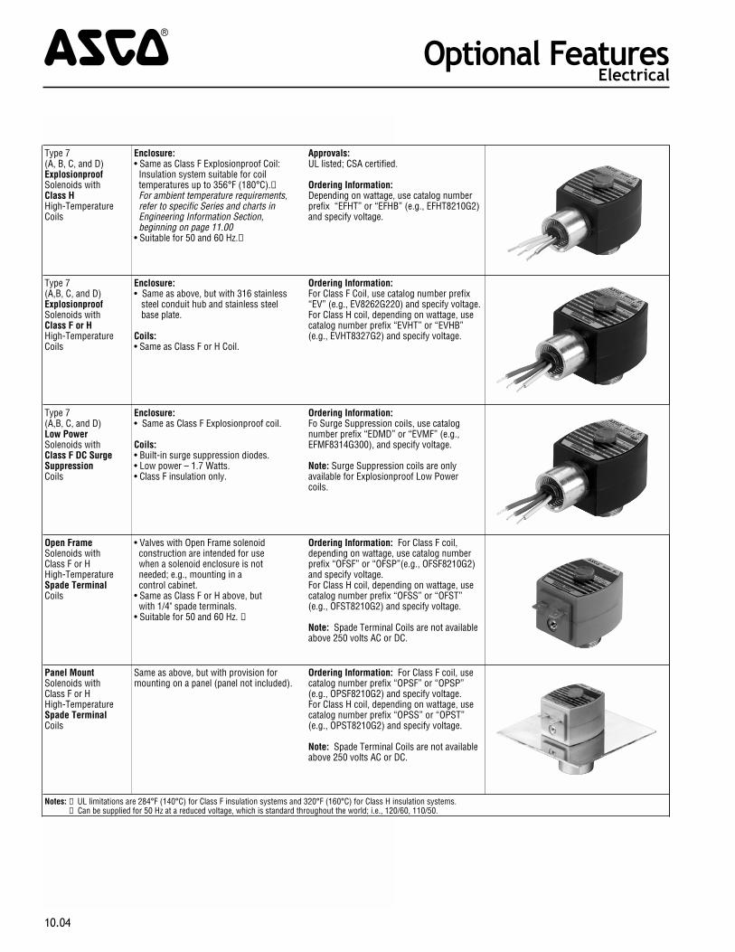
Type 7 (A, B, C, and D)ExplosionproofSolenoids with Class H High-TemperatureCoils
Enclosure: • Same as Class F Explosionproof Coil: Insulation system suitable for coil temperatures up to 356°F (180°C).➀ For ambient temperature requirements, refer to specific Series and charts in Engineering Information Section, beginning on page 11.00• Suitable for 50 and 60 Hz.➁
Approvals:UL listed; CSA certified.
Ordering Information: Depending on wattage, use catalog numberprefix “EFHT” or “EFHB” (e.g., EFHT8210G2)and specify voltage.
Type 7 (A,B, C, and D)ExplosionproofSolenoids with Class F or H High-TemperatureCoils
Enclosure: • Same as above, but with 316 stainless steel conduit hub and stainless steel base plate.
Coils:• Same as Class F or H Coil.
Ordering Information: For Class F Coil, use catalog number prefix“EV” (e.g., EV8262G220) and specify voltage. For Class H coil, depending on wattage, usecatalog number prefix “EVHT” or “EVHB”(e.g., EVHT8327G2) and specify voltage.
Type 7 (A,B, C, and D)Low PowerSolenoids with Class F DC Surge SuppressionCoils
Enclosure: • Same as Class F Explosionproof coil.
Coils:• Built-in surge suppression diodes.• Low power – 1.7 Watts.• Class F insulation only.
Ordering Information: Fo Surge Suppression coils, use catalognumber prefix “EDMD” or “EVMF” (e.g.,EFMF8314G300), and specify voltage.
Note: Surge Suppression coils are onlyavailable for Explosionproof Low Power coils.
Open FrameSolenoids with Class F or H High-TemperatureSpade Terminal Coils
• Valves with Open Frame solenoid construction are intended for use when a solenoid enclosure is not needed; e.g., mounting in a control cabinet.• Same as Class F or H above, but with 1/4" spade terminals.• Suitable for 50 and 60 Hz. ➁
Ordering Information: For Class F coil,depending on wattage, use catalog numberprefix “OFSF” or “OFSP”(e.g., OFSF8210G2)and specify voltage. For Class H coil, depending on wattage, usecatalog number prefix “OFSS” or “OFST”(e.g., OFST8210G2) and specify voltage.
Note: Spade Terminal Coils are not availableabove 250 volts AC or DC.
Panel MountSolenoids with Class F or H High-TemperatureSpade Terminal Coils
Same as above, but with provision formounting on a panel (panel not included).
Ordering Information: For Class F coil, usecatalog number prefix “OPSF” or “OPSP”(e.g., OPSF8210G2) and specify voltage.For Class H coil, depending on wattage, usecatalog number prefix “OPSS” or “OPST”(e.g., OPST8210G2) and specify voltage.
Note: Spade Terminal Coils are not availableabove 250 volts AC or DC.
Notes: ➀ UL limitations are 284°F (140°C) for Class F insulation systems and 320°F (160°C) for Class H insulation systems.Notes: ➁ Can be supplied for 50 Hz at a reduced voltage, which is standard throughout the world; i.e., 120/60, 110/50.
Optional Features4Electrical
10.04
Open FrameSolenoids with Class F or H High-TemperatureScrew Terminal Coils
• Valves with Open Frame solenoid construction are intended for use when a solenoid enclosure is not needed; e.g., mounting in a control cabinet.• Same as Class F or H above, but with #8 screws terminals.• Suitable for 50 and 60 Hz.➁
Ordering Information: For Class F coil, depending on wattage, usecatalog number prefix “OFKF” or “OFKP”(e.g., OFKF8210G2) and specify voltage. For Class H coil, depending on wattage, usecatalog number prefix “OFKH” or “OFKB” (e.g., OFKH8210G2) and specify voltage.
Note: Screw Terminal Coils are not availableabove 250 volts AC or DC.
Panel MountSolenoids with Class F or HHigh-Temperature Screw Terminal Coils
Coils:• Same as above, but with provision for mounting on a panel (panel not included).
Ordering Information: For Class F coil, depending on wattage, usecatalog number prefix “OPKF” or “OPKP”(e.g., OPKP8210G2) and specify voltage.For Class H coil, depending on wattage, use catalog number prefix “OPKH” or “OPKB” (e.g., OPKH8210G2) and specifyvoltage.
Note: Screw Terminal Coils are not availableabove 250 volts AC or DC.
Junction BoxSolenoids with Class F or H High-TemperatureSpade or Screw Terminal Coils
• Enclosures meet Type 1 General Purpose, Type 2 Dripproof, Types 3 and 3S Raintight, and Types 4 and 4X Watertight requirements.• Supplied standard with 1/2" threaded conduit hub and grounding provision.• Must be ordered with spade or screw terminals.
Ordering Information: For Class F coil, depending on wattage, usecatalog number prefix “JSF,” “JSP,” “JKF,” or“JKB” (e.g., JSF8210G2) and specify voltage.
For Class H coil, depending on wattage, usecatalog number prefix “JSS,” “JST,” “JKH,” or “JKB” (e.g., JKH8210G2) and specifyvoltage.
Note: Junction Box Options are not availableabove 250 volts AC or DC.
Class F GeneralPurpose Only withQuick Disconnect Pin Connectors
• Available for wattages 10.1, 17.1, 11.6, and 22.6.
• Materials: aluminum, stainless steel and non-metallic, 3 & 4 pin in popular sizes.
Ordering Information:For Class F coil, depending on wattage, usecatalog number prefix “VT” or “VB” andspecify voltage.
Notes: ➀ UL limitations are 284°F (140°C) for Class F insulation systems and 320°F (160°C) for Class H insulation systems.Notes: ➁ Can be supplied for 50 Hz at a reduced voltage, which is standard throughout the world; i.e., 120/60, 110/50.
Optional Features4Electrical
10.05
Class F or H High-TemperatureCoils with DIN Connections
• Meets ISO 4400/DIN 43650 requirements.• Class F insulation system suitable for coil temperatures up to 311°F (155°C).➀ For ambient temperature requirements, refer to specific Series and charts in Engineering Information Section, beginning on page 11.00.• Class H insulation system suitable for coil temperatures up to 356°F (180°C).➀ For ambient temperature requirements, refer to specific Series and charts in Engineering Information Section, beginning on page 11.00.• Enclosure protection with DIN connector equivalent to Types 1 and 4.• Suitable for 50 and 60 Hz.➁
Ordering Information: For Class F Coil,depending on wattage, use catalog numberprefix “SC” or “SD” (e.g., SC8210G2) andspecify voltage.
For Class H coil, depending on wattage, usecatalog number prefix "SU" or "SV" (e.g.,SU8210G2) and specify voltage.
Note: Optional DIN-type strain-reliefconnector kit includes a gasket and mounting screw. Outlet accommodates cablewith O.D. of 0.310" to 0.400".
Note: DIN Connection Coils are not availableabove 250 volts AC or DC.
Must be ordered separately as Kit No.K236034.
Junction Box for Class F or H Coils
Junction box (shown installed onRed-Hat II solenoid) is a zinc coated steelhousing with two 7/8" knock-outs forthrough wiring. UL listed when orderedfactory assembled. Also available, withoutUL listing, as a kit with grounding screw forfield installation.
Ordering Information:For factory assembly, add prefix “JB” to Valve Catalog Number. For kit, use numberK272140.
Sub-Miniature Coilsfor Series 8225, 8325, 8280, 8380,8401, and 8551Class F High-Temperature Molded Coils withDIN Connection
These sub-miniature coils meet 3 x DIN46244 requirements.• Insulation system suitable for coil temperatures up to 311°F (155°C).➀ For ambient temperature requirements, refer to specific Series and charts in Engineering Information Section, beginning on page 11.00.• Suitable for 50 and 60 Hz.➁• “Enclosure Protection” with DIN connector equivalent to Types 1 and 4.
Note: Optional DIN-type strain-reliefconnector kit includes a gasket and mountingscrew. Outlet accommodates cables with O.D.of 0.310" to 0.400". Must be ordered separately as Kit No.K226061-1.
1/2" ThreadedConduit Hubs
These conventional threaded hubs allowconnection with 1/2" BX cable. Can besupplied with leaded coil only. Kit includesgasket and attaching screw.
Ordering Information: Order separate Kit No.K224735.
Notes: ➀ UL limitations are 284°F (140°C) for Class F insulation systems and 320°F (160°C) for Class H insulation systems.Notes: ➁ Can be supplied for 50 Hz at a reduced voltage, which is standard throughout the world; i.e., 120/60, 110/50.
Optional Features4Electrical
10.06
Construction
Standard valve construction materials for standard valves are shown on the Seriespages. If handling fluids other than those listed in the Specifications section, youmay require special constructions, however. The most frequently used elastomersare listed in Table 4 along with the Valve Series in which they are available. Otherconsiderations for a variety of liquids and gases are included in the Valve MaterialSelection Guide, which starts on page 11.20. A solenoid valve must use certainconstruction material for proper electrical function. If you cannot find the specificfluid in the guide, please consult your local ASCO office.
Certain fluids may also require that we change the solenoid shading coil. Thestandard valves use a copper shading coil. Aluminum and silver are also availableand, due to their different magnetic properties, additional electrical changes maybe necessary. When a change in shading coil material is indicated in the guide,please consult your local ASCO office.
Table 4: Optional Construction Features for ASCO Solenoid Valves Handling Liquids and Gases other than Air, Inert Gas,Water, and Light Oil. Orders entered using this table MUST state actual fluid and pressure of application.
Optional Construction Features
Optional Features4
10.07
Pipe Size (ins.)
Series Number orValve Type Valve Construction Number
Special Construction Features ➂ELASTOMERS
EPDMOxygenService PTFE FKM CR
Use Suffix “E”
Use Suffix“N” ➀
Use Suffix “T” ➁
Use Suffix “V”
Use Suffix “J”
SOLENOID OPERATED VALVES
3/8 - 3/4 8030, 8040 1-10, 13
Avai
labl
e on
all
cons
truct
ions
Avai
labl
e on
all
cons
truct
ions
Not Available Available
Avai
labl
e on
all
cons
truct
ions
3/8 - 1 1/2 8210 1, 2, 5, 6, 7, 8, 9, 11, 12, 16, 18, 23,24, 25, 26, 28, 29, 31-51 Not Available Available
3/4 - 2 1/2 8210 10, 20, 21, 27, 30 Available Available
3/8 - 3 8215 All Not Available Available
All 8260 1, 2, 3 Not Available Available
All 8260 4, 5, 6 Not Available Not Available
1/8 - 3/8 8262, 8263 1 - 7, 11, 12, 13, 16, 17 Available Available
1/8 & 1/4 8262 8, 9, 14 Available Available
3/8 & 1/2 8316 1, 2 Not Available Available
3/4 & 1 8316 3, 4, 5 Not Available Available
All 8320, 8360 All Available Available
AIR OPERATED VALVES
1/4 2 Ports 1, 2, 22
Avai
labl
e on
all
cons
truct
ions
Avai
labl
e on
all
cons
truct
ions
Available Available
Avai
labl
e on
all
cons
truct
ions3/8 - 3/4 2 Ports 8 Not Available Available
3/8 - 3/4 2 Ports 3, 4 Not Available Not Available
3/8 - 3/4 2 Ports 6, 7, 16, 17 Not Available Available
1 & 1 1/4 2 Ports 10, 12, 18, 19 Not Available Available
1 1/2 2 Ports 14, 20 Not Available Available
1/4 3 Ports 1 Available Available
3/8 & 1/2 3 Ports 2 Not Available Available
3/4 & 1 3 Ports 3, 4 Not Available Not AvailableNotes: ➀ For valves requiring special cleaning and/or testing procedures, such as for oxygen, freon, & sanitary service, refer to Table 6.Notes: ➁ Pressure ratings must be reduced by 25%.Notes: ➂ Unless otherwise indicated in the Series Specification Tables, all soft seating valves are supplied with NBR discs, diaphragms, or gaskets.
Manual OperatorsManual operators are provided to operate the valve manually when electricpower is off. There are basically two types of manual operators: momentary and maintained. Series 8320, 8321, and 8342 can be fitted with either type.
To determine which type is available for your valves, check the ConstructionReference Numbers in their Series Specification Tables against the Table below.Schematics of the manual operators and how they are fitted to the valves areshown on the right. If no manual operator is listed or a different type isrequired, consult your local ASCO office. Add suffix “MO” or “MS” to thecatalog number.
Table 5: Manual Operators
ConstructionOptional Features4
10.08
MANUAL OPERATORS ➃ FOR 2 WAY SOLENOID VALVES
SeriesNumber
Pipe Size(ins.)
Valve Construction Reference
NumberValve BodyMaterials
ManualOperator
Suffix
Type ofManualOperator
IllustrationNumber
8030 3/8, 1/2 1, 2, 3, 11 Brass MO Maintained 58030 3/4 9 Brass MO Maintained 38030 3/8, 1/2 1, 2, 3, 11 Stainless Steel MO Maintained 58030 3/4 10 Stainless Steel MO Maintained 38210 3/8, 1/2 1, 2 Stainless Steel MO Maintained 58210 3/8, 1/2 1, 2 Brass MO Maintained 5
8210 3/8 to 2 1/2 3, 5, 6, 8, 9, 11, 12, 16, 18, 20, 21 Brass MO Maintained 2
8210 3/4 to 1 1/2 10, 31, 32, 33 Brass MO Maintained 38210 1 42 Brass MO Maintained 48210 3/4 7 Stainless Steel MO Maintained 28221 3/8 to 3/4 1, 2, 5, 6 ,7, 11, 12 Brass MO Maintained 28262 1/8 1 Brass MO Maintained 38262 1/8 1 Stainless Steel MO Maintained 3
8262 1/8 8 Brass MSMO
MaintainedMomentary
31
8262 1/8 8 Stainless Steel MSMO
MaintainedMomentary
31
8262 1/4 2, 4, 6, 16, 17 Brass MO Maintained 28262 1/4 11, 12 ,13 Stainless Steel MO ➅ Maintained 28263 3/8 3, 5, 7 Brass MO Maintained 2
MANUAL OPERATORS ➃ FOR 3 WAY SOLENOID VALVES8300 All All Brass MO Maintained 48300 All All Stainless Steel MO Maintained 48316 All All Brass MO Maintained 2
8320 1/8, 1/4 All BrassStainless Steel } { MS ➄
MO ➀MaintainedMomentary
31
8321 All All Brass MSMO
MaintainedMomentary
31
MANUAL OPERATORS ➃ FOR 4 WAY SOLENOID VALVES8340 1/4 8340A1, A3, A4 Aluminum MO Momentary 1
8342 1/4, 3/8 Single Solenoid Only BrassStainless Steel
MS MO } Maintained
Momentary41
8344 ➂ All All Brass MO Maintained 28345 1/4 1 Brass MO Maintained 5
8401 1/8, 1/4 All Aluminum ➁ MomentaryMaintained
——
MANUAL OPERATORS ARE ALSO AVAILABLE FOR ALL LOW POWER AND INTRINSICALLY SAFE VALVES (MANUAL OR MOMENTARY). USE SUFFIX “MO.” Notes: ➀ Limited to 100 psi (7 bar) maximum on Normally Open and Universal operation. Notes: ➁ Supplied as standard, no suffix required. Notes: ➂ Two manual operators required for Dual Solenoid construction. Notes: ➃ Limited to 250 psi (17 bar) pressure, except where noted otherwise. Notes: ➄ Valves with MS suffix maintain full catalog ratings. Notes: ➅ Manual operator not available for this series with steam application.
Construction
Metering DevicesMetering Devices are used for obtaining an exact flow fromsolenoid valves for dispensing or for moving an air operator in agiven time period. Valves which can be fitted with metering devicesare Series 8262 (1/8" NPT size only), 8260, 8401, 8402, and 8342.Add suffix “M” to catalog numbers.
Special Cleaning and Testing Procedures:If special cleaning and testing procedures are required, they must
be specified when ordered. These procedures cannot be done afterthe valve is built.
Fluid Description of Cleaning or Testing Procedure Order by Specifying
Freon All valve parts inspected for oil, grease, metaldust, and other foreign matter and degreased, ifnecessary. Assembled in clean, dry area andhelium mass spectrometer tested for externalleakage. Pipe connections sealed with plugs.
Clean and test per ASCO AP-1-005Procedure.
Oxygen All valve parts degreased and blacklightinspected for cleanliness. Assembled and testedin clean area using oil-free air or nitrogen.Helium mass spectrometer tested for externalleakage. Pipe connections sealed with plugs.Each valve tagged covering certification of testsand put in a sealed bag.
Clean and test per ASCO AP-1-004Procedure. Add Suffix "N" to catalogNumber.
Sanitary distilledwater and otherclean systems
All valve parts inspected for oil, grease, metaldust, and other foreign matter and degreased, ifnecessary. Valves assembled in clean area andtested with clean, dry air or nitrogen. Pipeconnections sealed with plugs.
Clean and test per ASCO AP-1-008Procedure.
Table 6: ASCO Special Cleaning and Testing Procedures