29
Advanced Vanadium Flow Batteries and Applications for Renewable Integration Vanadis Power GmbH July 5 th , 2013
Advanced Vanadium Flow Batteries
and Applications for Renewable Integration
Vanadis Power GmbH
July 5th, 2013
Dr. Andreas Luczak
2
Personal data
44 years old
Education
Dr. rer. nat (PhD) in Physics
Professional experience
1994-1996: Research Associate Laser Laboratory Goettingen
1996-1999: Software Engineering Siemens Power Generation
1999-2003: Innovation Manager Siemens Industrial Services
2003-2008: Head of R&D group Siemens Automotive Projects
2008-2012: Business Development & Project Management Siemens PV Inverters
2012-2013: Head of Siemens Energy Storage Solutions
Since 2013: Managing Director of Vanadis Power GmbH
Vanadis Power GmbH
3
Vanadis was founded end of 2012 to bring to the European market Advanced
Vanadium Flow Batteries for integration of renewable energy & other applications.
Through innovation, expertise and global strategic partnerships, Vanadis’ mission is to
become a leader in large- and medium-scale energy storage in Europe.
Our activities are sales, project management, system deployment (focus on PCS and
grid integration) and services.
Origin of the company name:
„Vanadis“ is the name of a goddess associated with beauty.
Vanadium was called after this goddess due to the many beautifully colored chemical
compounds it produces.
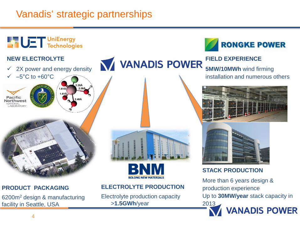
PRODUCT PACKAGING
6200m2 design & manufacturing
facility in Seattle, USA
ELECTROLYTE PRODUCTION
Electrolyte production capacity
>1.5GWh/year
STACK PRODUCTION
More than 6 years design &
production experience
Up to 30MW/year stack capacity in
2013
FIELD EXPERIENCE
5MW/10MWh wind firming
installation and numerous others
NEW ELECTROLYTE
2X power and energy density
–5°C to +60°C
Vanadis‘ strategic partnerships
4
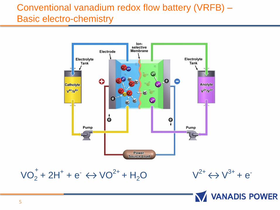
Conventional vanadium redox flow battery (VRFB) –
Basic electro-chemistry
5
V2+ ↔ V3+
+ e-VO2 + 2H+
+ e- ↔ VO2+
+ H2O +
Conventional VRFB’s have many advantages
6
• Separation of power (KW) -stacks - and energy (KWh) – electrolytes -> each can be individually sized according to application needs
• Adding additional energy just requires bigger electrolyte tanks which is simple and quite cheap
• No self discharge in electrolyte tanks
• “Inert” electrodes – no structural changes or stress buildup
- long cycle life & shelf life, independent of state of charge/depth of discharge
• Inherent active heat management – flowing electrolytes carry away heat generated from electro-chemical reactions -> Uncontrollable fire known with NaS, Lead Acid and Li-Ion applications not possible
• Environmentally friendly since electrolyte only changes the ion valence during operation and can be virtually be reused forever
• Highly dynamic in the millisecond range with high overload capacity
• Capable of storing large quantities of energy (MWh’s) for long periods and discharging upon need
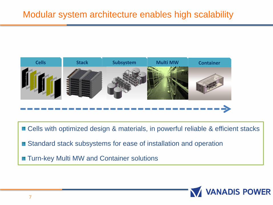
Modular system architecture enables high scalability
Cells with optimized design & materials, in powerful reliable & efficient stacks
Standard stack subsystems for ease of installation and operation
Turn-key Multi MW and Container solutions
Cells Stack Container Subsystem Multi MW
7
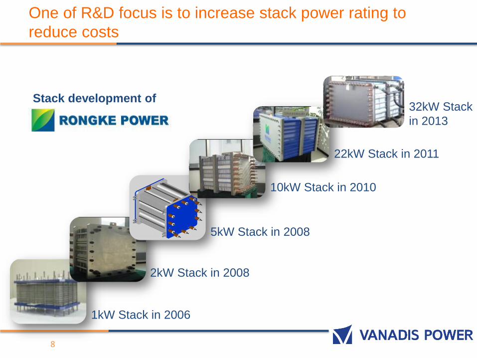
One of R&D focus is to increase stack power rating to
reduce costs
32kW Stack
in 2013
1kW Stack in 2006
2kW Stack in 2008
5kW Stack in 2008
10kW Stack in 2010
8
22kW Stack in 2011
Stack development of
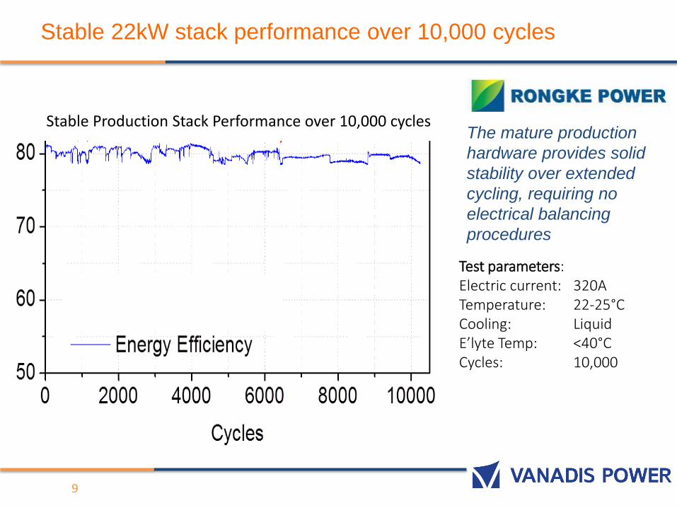
Stable 22kW stack performance over 10,000 cycles
9
The mature production
hardware provides solid
stability over extended
cycling, requiring no
electrical balancing
procedures
Test parameters: Electric current: 320ATemperature: 22-25°CCooling: LiquidE’lyte Temp: <40°CCycles: 10,000
Stable Production Stack Performance over 10,000 cycles
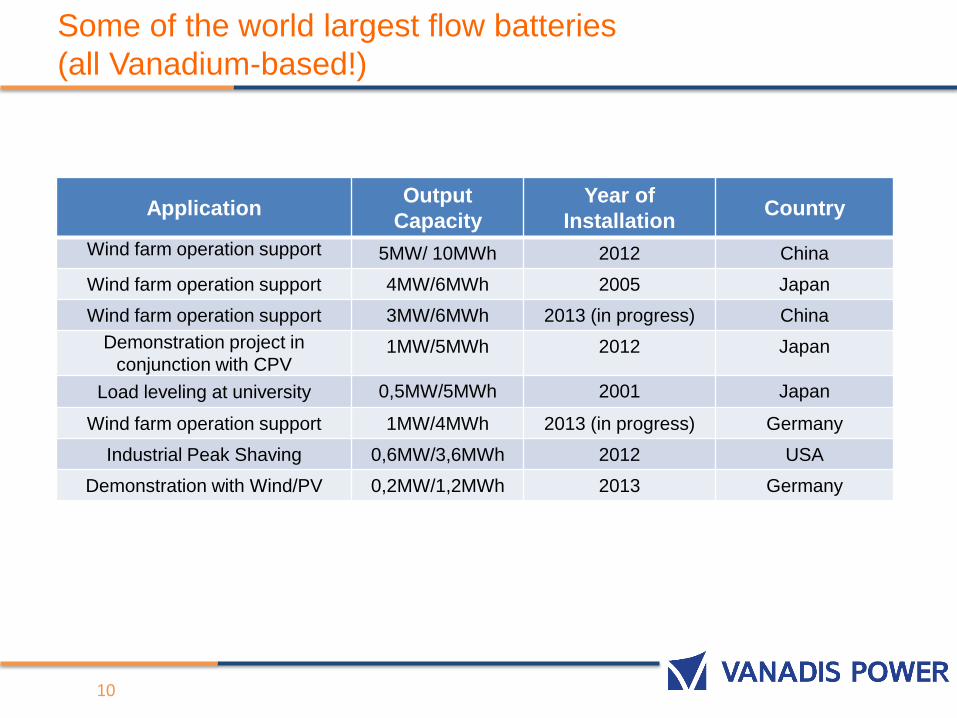
Some of the world largest flow batteries
(all Vanadium-based!)
ApplicationOutput
Capacity
Year of
InstallationCountry
Wind farm operation support 5MW/ 10MWh 2012 China
Wind farm operation support 4MW/6MWh 2005 Japan
Wind farm operation support 3MW/6MWh 2013 (in progress) China
Demonstration project in
conjunction with CPV1MW/5MWh 2012 Japan
Load leveling at university 0,5MW/5MWh 2001 Japan
Wind farm operation support 1MW/4MWh 2013 (in progress) Germany
Industrial Peak Shaving 0,6MW/3,6MWh 2012 USA
Demonstration with Wind/PV 0,2MW/1,2MWh 2013 Germany
10
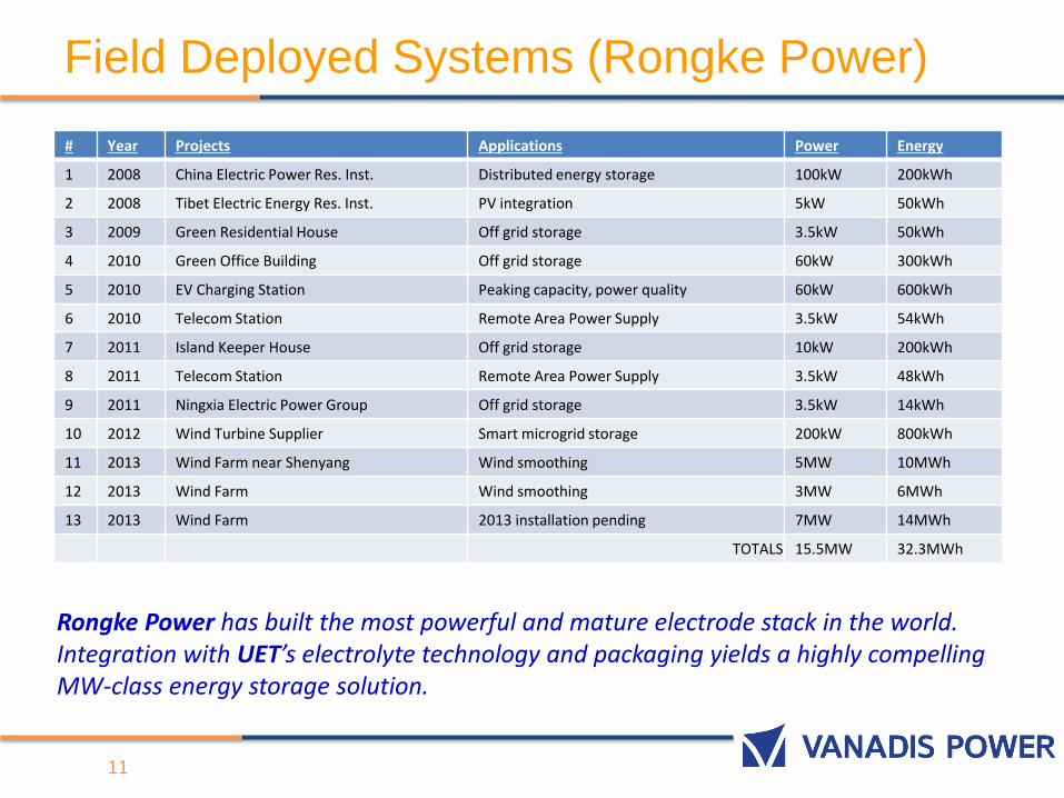
Field Deployed Systems (Rongke Power)
11
# Year Projects Applications Power Energy
1 2008 China Electric Power Res. Inst. Distributed energy storage 100kW 200kWh
2 2008 Tibet Electric Energy Res. Inst. PV integration 5kW 50kWh
3 2009 Green Residential House Off grid storage 3.5kW 50kWh
4 2010 Green Office Building Off grid storage 60kW 300kWh
5 2010 EV Charging Station Peaking capacity, power quality 60kW 600kWh
6 2010 Telecom Station Remote Area Power Supply 3.5kW 54kWh
7 2011 Island Keeper House Off grid storage 10kW 200kWh
8 2011 Telecom Station Remote Area Power Supply 3.5kW 48kWh
9 2011 Ningxia Electric Power Group Off grid storage 3.5kW 14kWh
10 2012 Wind Turbine Supplier Smart microgrid storage 200kW 800kWh
11 2013 Wind Farm near Shenyang Wind smoothing 5MW 10MWh
12 2013 Wind Farm Wind smoothing 3MW 6MWh
13 2013 Wind Farm 2013 installation pending 7MW 14MWh
TOTALS 15.5MW 32.3MWh
Rongke Power has built the most powerful and mature electrode stack in the world. Integration with UET’s electrolyte technology and packaging yields a highly compelling MW-class energy storage solution.
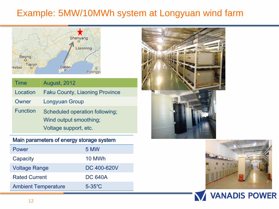
Example: 5MW/10MWh system at Longyuan wind farm
Time August, 2012
Location Faku County, Liaoning Province
Owner Longyuan Group
Function Scheduled operation following;
Wind output smoothing;
Voltage support, etc.
Main parameters of energy storage system
Power 5 MW
Capacity 10 MWh
Voltage Range DC 400-620V
Rated Current DC 640A
Ambient Temperature 5-35℃
12
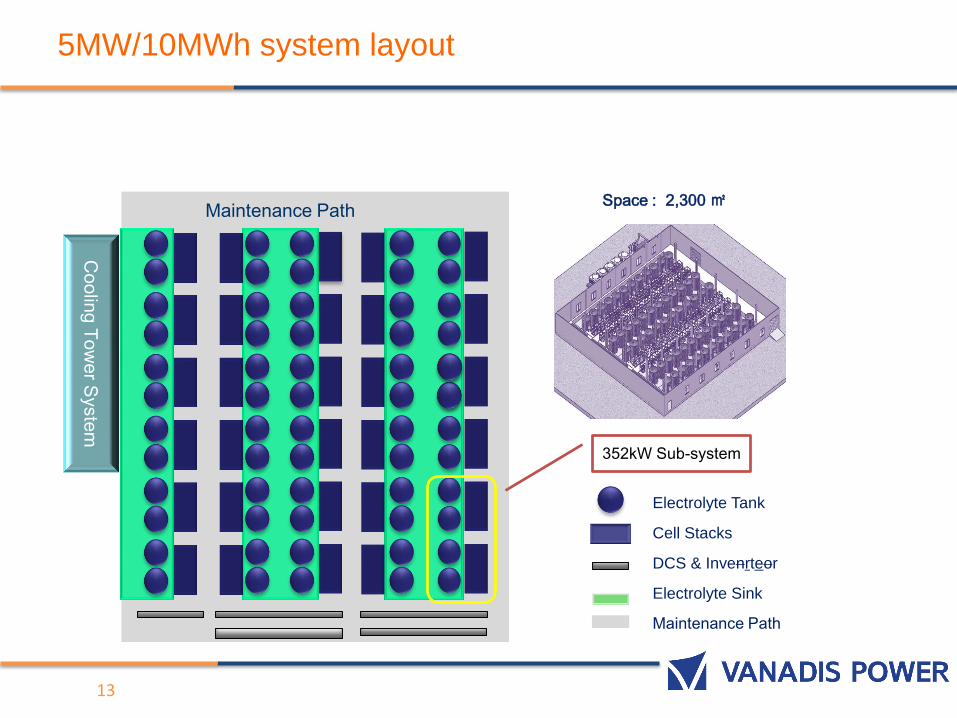
5MW/10MWh system layout
Electrolyte Tank
Cell Stacks
DCS & Invenrteor
Electrolyte Sink
Maintenance Path
Space : 2,300 ㎡
Co
olin
g T
ow
er S
yste
m
Maintenance Path
352kW Sub-system
13
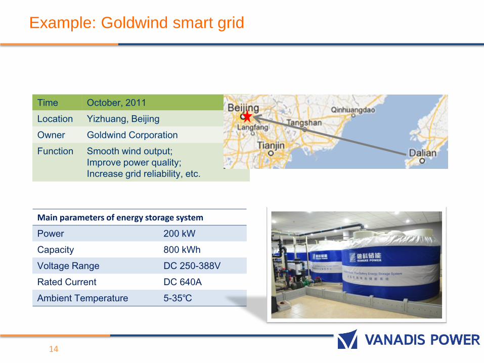
Example: Goldwind smart grid
Time October, 2011
Location Yizhuang, Beijing
Owner Goldwind Corporation
Function Smooth wind output;
Improve power quality;
Increase grid reliability, etc.
Main parameters of energy storage system
Power 200 kW
Capacity 800 kWh
Voltage Range DC 250-388V
Rated Current DC 640A
Ambient Temperature 5-35℃
14
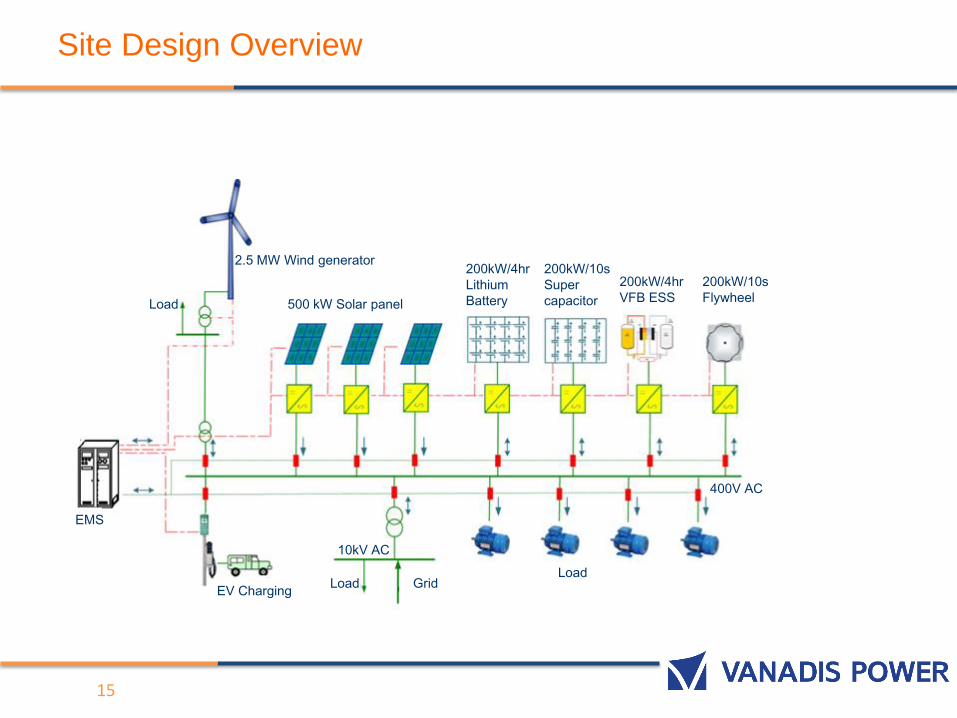
Site Design Overview
15
2.5 MW Wind generator
500 kW Solar panel
200kW/4hr
Lithium
Battery
200kW/10s
Super
capacitor
200kW/4hr
VFB ESS
200kW/10s
Flywheel
400V AC
10kV AC
LoadLoad
GridEV Charging
EMS
Load
16
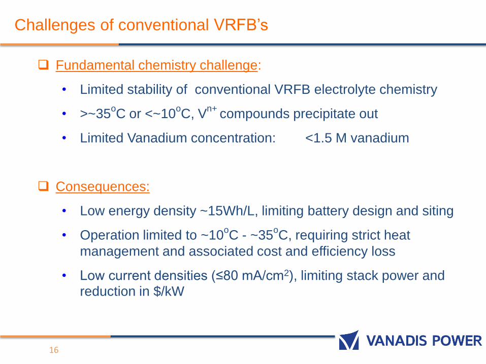
Challenges of conventional VRFB’s
Fundamental chemistry challenge:
• Limited stability of conventional VRFB electrolyte chemistry
• >~35oC or <~10
oC, V
n+ compounds precipitate out
• Limited Vanadium concentration: <1.5 M vanadium
Consequences:
• Low energy density ~15Wh/L, limiting battery design and siting
• Operation limited to ~10oC - ~35
oC, requiring strict heat
management and associated cost and efficiency loss
• Low current densities (≤80 mA/cm2), limiting stack power and reduction in $/kW
17
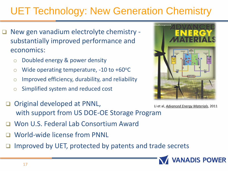
New gen vanadium electrolyte chemistry -substantially improved performance and economics:
o Doubled energy & power density
o Wide operating temperature, -10 to +60oC
o Improved efficiency, durability, and reliability
o Simplified system and reduced cost
Original developed at PNNL, with support from US DOE-OE Storage Program
Won U.S. Federal Lab Consortium Award
World-wide license from PNNL
Improved by UET, protected by patents and trade secrets
Li et al, Advanced Energy Materials, 2011
UET Technology: New Generation Chemistry
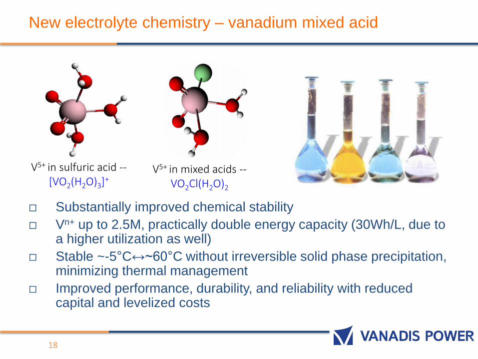
New electrolyte chemistry – vanadium mixed acid
Substantially improved chemical stability
Vn+ up to 2.5M, practically double energy capacity (30Wh/L, due to a higher utilization as well)
Stable ~-5°C↔~60°C without irreversible solid phase precipitation, minimizing thermal management
Improved performance, durability, and reliability with reduced capital and levelized costs
18
V5+ in mixed acids --VO2Cl(H2O)2
V5+ in sulfuric acid --[VO2(H2O)3]+
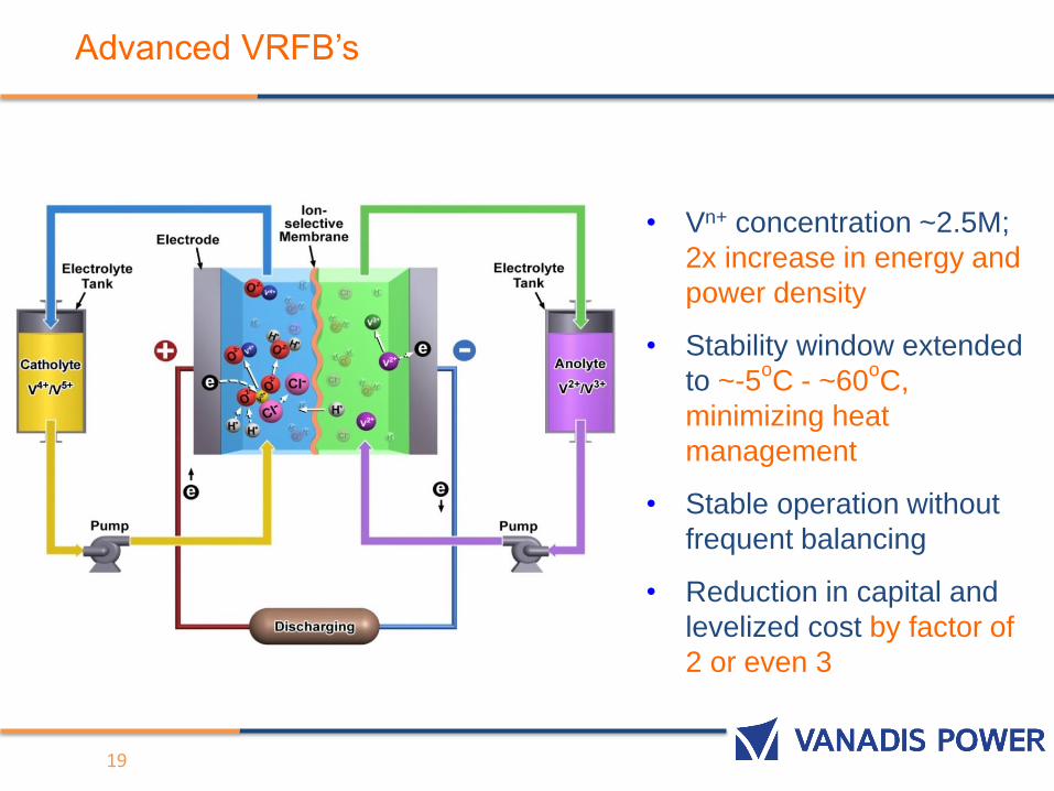
Advanced VRFB’s
• Vn+ concentration ~2.5M;
2x increase in energy and
power density
• Stability window extended
to ~-5oC - ~60
oC,
minimizing heat
management
• Stable operation without
frequent balancing
• Reduction in capital and
levelized cost by factor of
2 or even 3
19
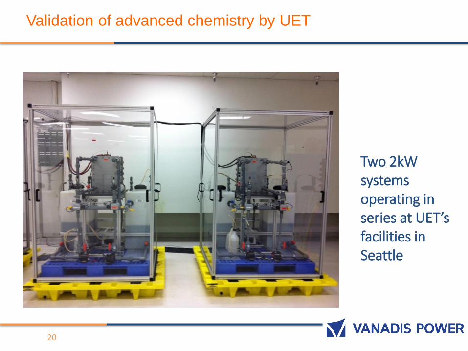
Validation of advanced chemistry by UET
20
Two 2kW systems operating in series at UET’s facilities in Seattle
0
5
10
15
20
25
30
35
40
45
50
50
60
70
80
90
100
110
120
130
140
150
6 120 312 471 601 615 636 650 668 680 695 710 720
Ener
gy D
ensi
ty /
Wh
/L
Dis
char
ge C
apac
ity
/ A
h
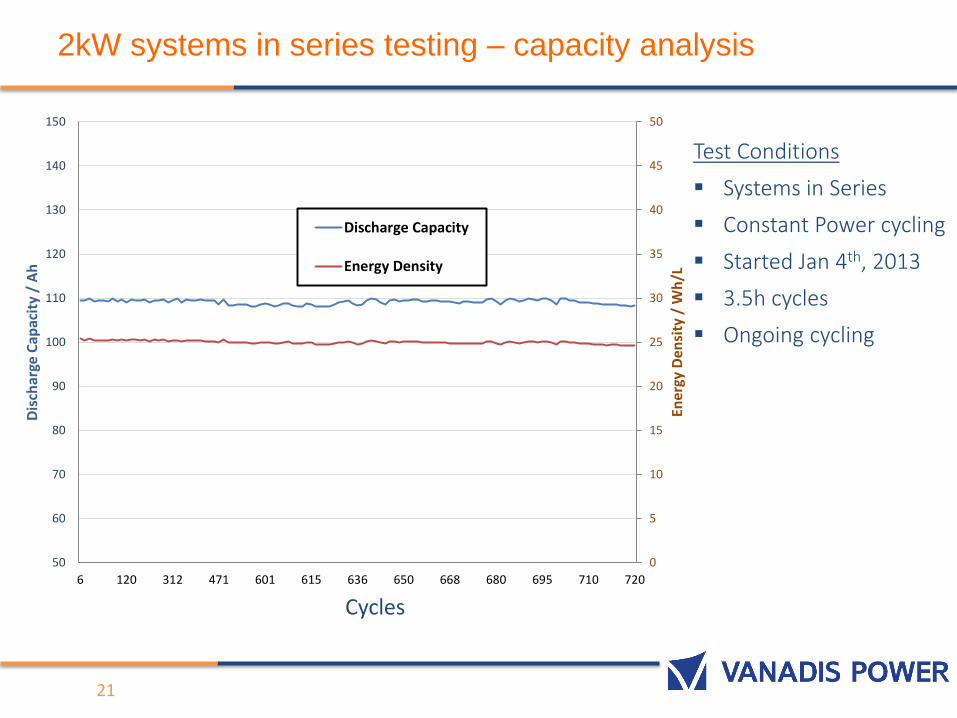
Discharge Capacity
Energy Density
2kW systems in series testing – capacity analysis
21
Test Conditions
Systems in Series
Constant Power cycling
Started Jan 4th, 2013
3.5h cycles
Ongoing cycling
Cycles
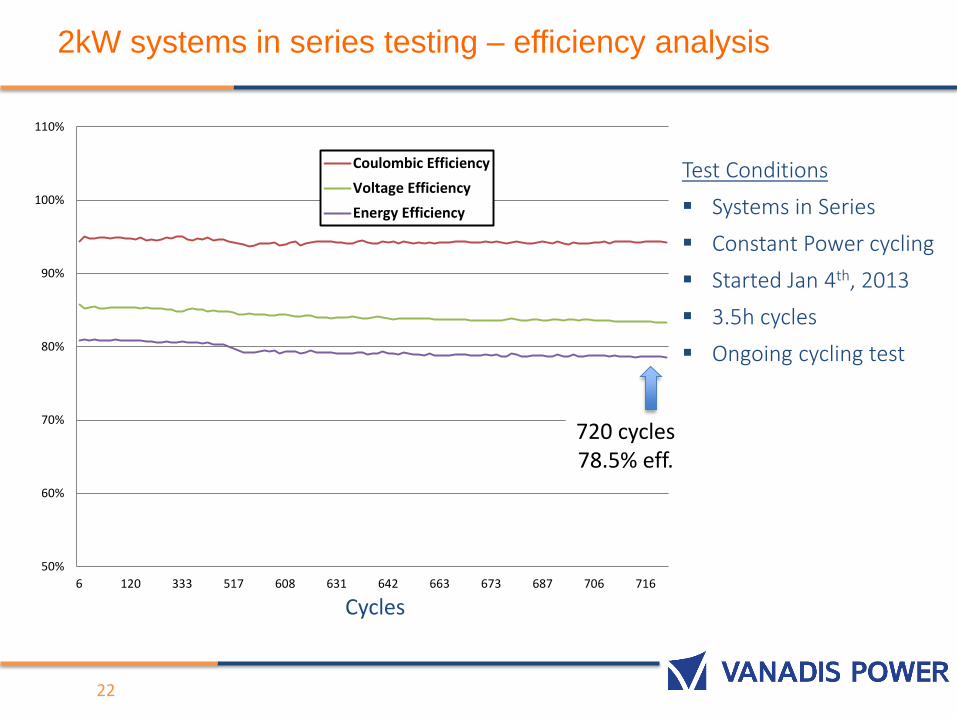
2kW systems in series testing – efficiency analysis
50%
60%
70%
80%
90%
100%
110%
6 120 333 517 608 631 642 663 673 687 706 716
Coulombic Efficiency
Voltage Efficiency
Energy Efficiency
22
Test Conditions
Systems in Series
Constant Power cycling
Started Jan 4th, 2013
3.5h cycles
Ongoing cycling test
720 cycles78.5% eff.
Cycles
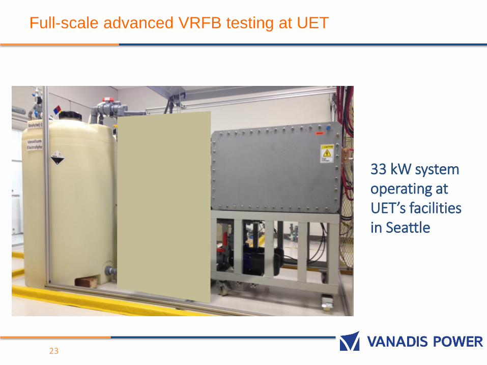
Full-scale advanced VRFB testing at UET
23
33 kW system operating at UET’s facilities in Seattle
24
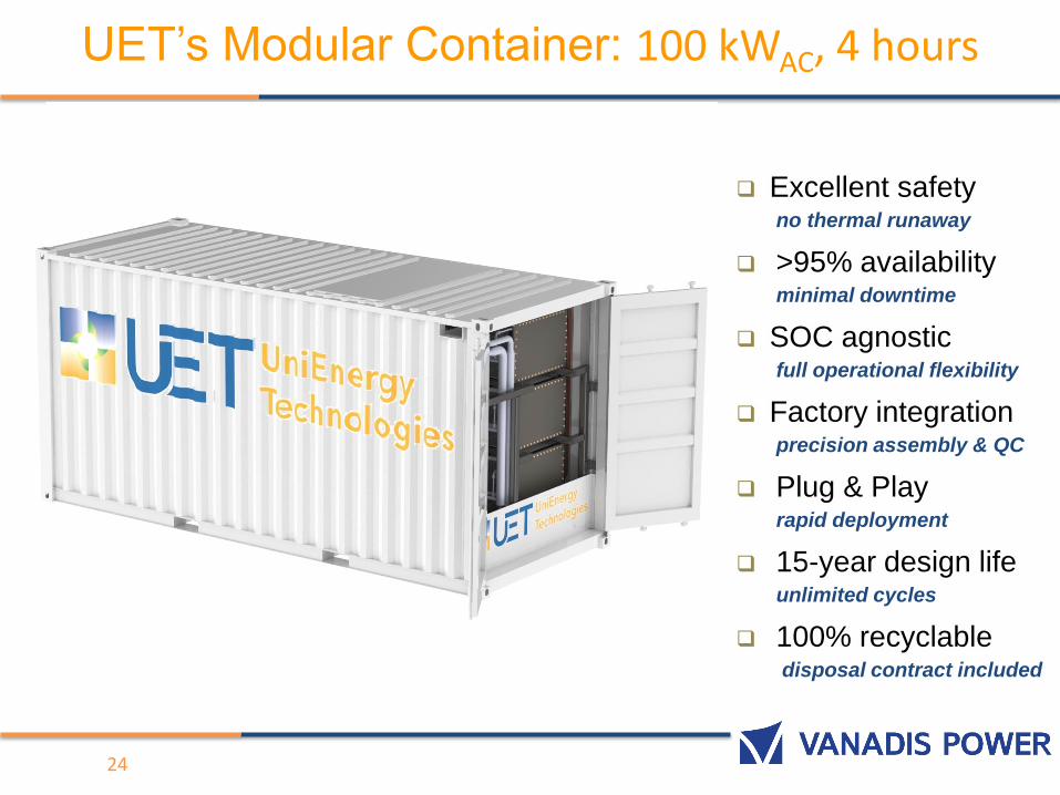
Excellent safetyno thermal runaway
>95% availabilityminimal downtime
SOC agnosticfull operational flexibility
Factory integrationprecision assembly & QC
Plug & Playrapid deployment
15-year design lifeunlimited cycles
100% recyclabledisposal contract included
UET’s Modular Container: 100 kWAC, 4 hours
25
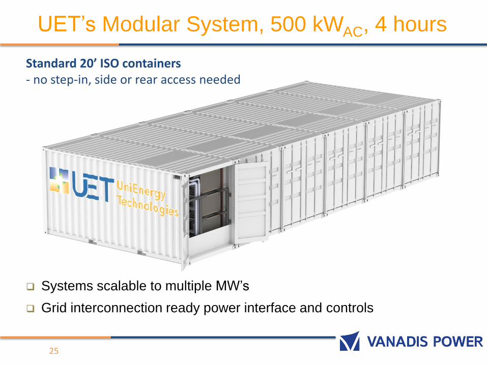
UET’s Modular System, 500 kWAC, 4 hours
Standard 20’ ISO containers- no step-in, side or rear access needed
Systems scalable to multiple MW’s
Grid interconnection ready power interface and controls
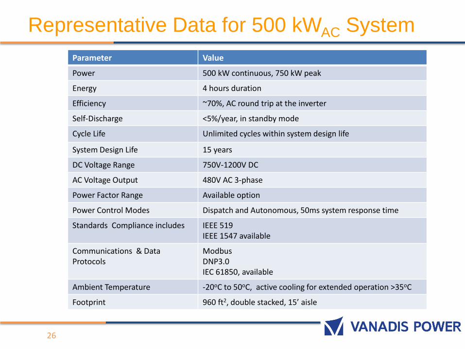
Representative Data for 500 kWAC System
26
Parameter Value
Power 500 kW continuous, 750 kW peak
Energy 4 hours duration
Efficiency ~70%, AC round trip at the inverter
Self-Discharge <5%/year, in standby mode
Cycle Life Unlimited cycles within system design life
System Design Life 15 years
DC Voltage Range 750V-1200V DC
AC Voltage Output 480V AC 3-phase
Power Factor Range Available option
Power Control Modes Dispatch and Autonomous, 50ms system response time
Standards Compliance includes IEEE 519IEEE 1547 available
Communications & Data Protocols
ModbusDNP3.0IEC 61850, available
Ambient Temperature -20oC to 50oC, active cooling for extended operation >35oC
Footprint 960 ft2, double stacked, 15’ aisle
27
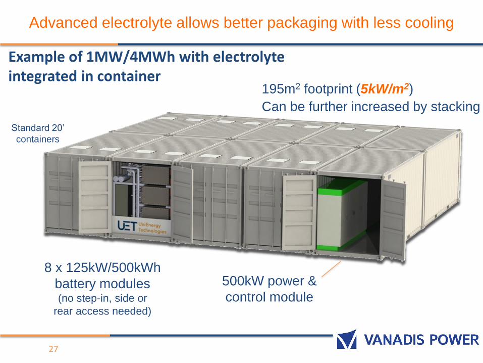
500kW power &
control module
8 x 125kW/500kWh
battery modules(no step-in, side or
rear access needed)
195m2 footprint (5kW/m2)
Can be further increased by stacking
Standard 20’
containers
Example of 1MW/4MWh with electrolyteintegrated in container
Advanced electrolyte allows better packaging with less cooling
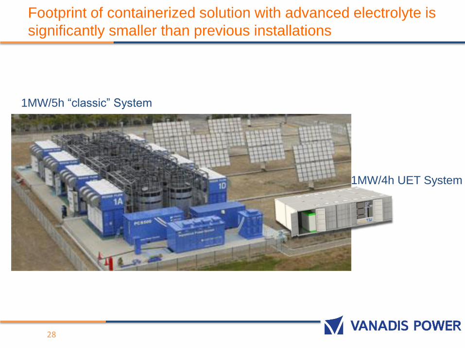
Footprint of containerized solution with advanced electrolyte is
significantly smaller than previous installations
28
1MW/5h “classic” System
1MW/4h UET System
Thank you!
Dr. Andreas Luczak
Vanadis Power GmbH
: Zeltnerstr. 3
90443 Nuremberg, Germany
: +49 911 8819 7218


