PAGE REVISION: DATE: VAN'S AIRCRAFT, INC. SECTION 49: FUEL & OIL SYSTEM NOTES: Tri-Gear shown. No special tools required to complete this section. PARTICIPANTS: 07/21/20 1 RV-14 DATE OF COMPLETION: 49-01 VENT SCAT 5X21 SCAT DUCT VA-119 HOSE ASY-4X21.5 EA-00002 OIL COOLER 2006X FF-01406C OIL COOLER INLET SIDES FF-01404 OIL COOLER TRAY FF-01405 CHANNEL BRACE VA-190 HOSE ASY-8X26.875 FF-00015 HOSE ASY-6X11.125 FF-00004 BREATHER TUBE FF-00019 HOSE ASY-6X19 VA-102 HOSE ASY-4X15.25 VA-139 HOSE ASY-6X15.75 FF-01412 BREATHER HOSE FF-00020 HOSE ASY-8X19 FF-01406E OIL COOLER INLET, 5 IN
Transcript
PAGEREVISION:DATE:
VAN'S AIRCRAFT, INC.
SECTION 49:FUEL & OIL SYSTEM
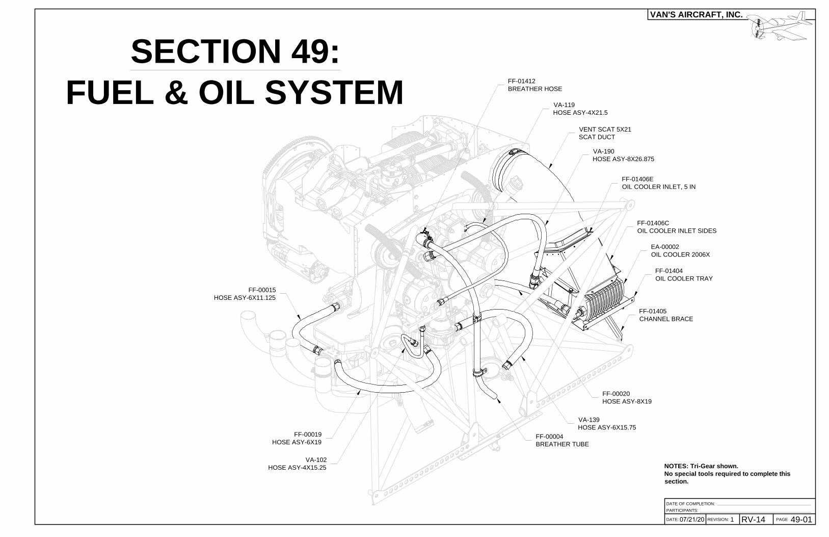
NOTES: Tri-Gear shown.No special tools required to complete thissection.
PARTICIPANTS:
07/21/20 1 RV-14
DATE OF COMPLETION:
49-01
VENT SCAT 5X21SCAT DUCT
VA-119HOSE ASY-4X21.5
EA-00002OIL COOLER 2006X
FF-01406COIL COOLER INLET SIDES
FF-01404OIL COOLER TRAY
FF-01405CHANNEL BRACE
VA-190HOSE ASY-8X26.875
FF-00015HOSE ASY-6X11.125
FF-00004BREATHER TUBE
FF-00019HOSE ASY-6X19
VA-102HOSE ASY-4X15.25
VA-139HOSE ASY-6X15.75
FF-01412BREATHER HOSE
FF-00020HOSE ASY-8X19
FF-01406EOIL COOLER INLET, 5 IN
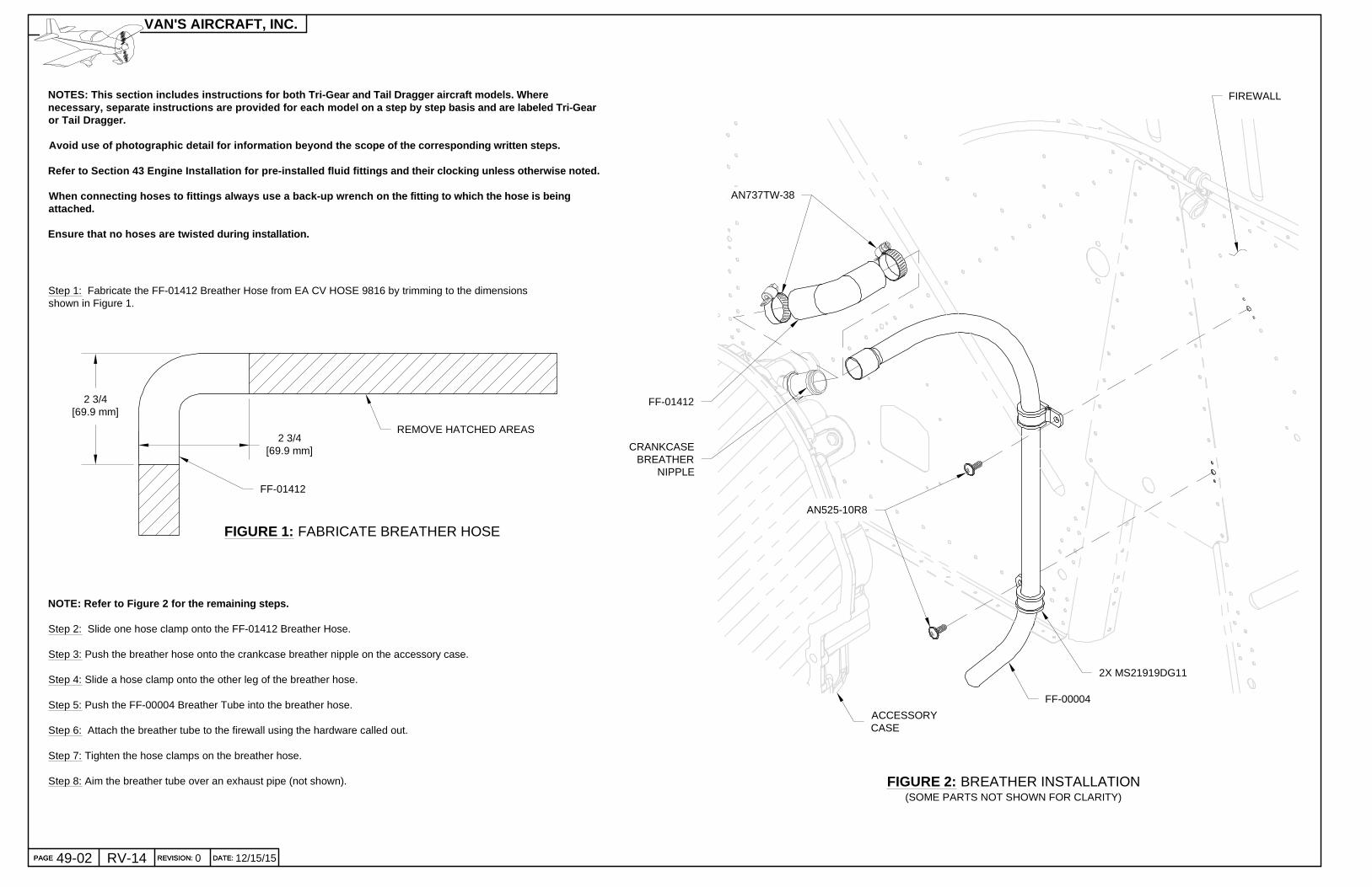
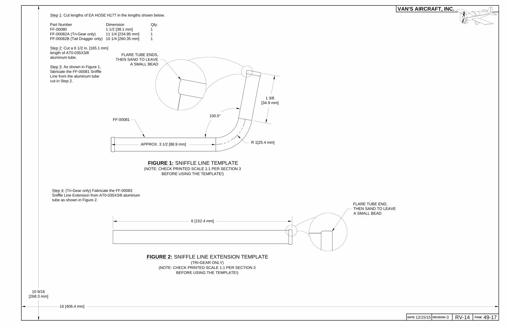
Step 1: Fabricate the FF-01412 Breather Hose from EA CV HOSE 9816 by trimming to the dimensionsshown in Figure 1.
FIGURE 2: BREATHER INSTALLATION(SOME PARTS NOT SHOWN FOR CLARITY)
FF-00004
FF-01412
AN737TW-38
AN525-10R8
2X MS21919DG11
ACCESSORYCASE
FIGURE 1: FABRICATE BREATHER HOSE
NOTE: Refer to Figure 2 for the remaining steps.
Step 2: Slide one hose clamp onto the FF-01412 Breather Hose.
Step 3: Push the breather hose onto the crankcase breather nipple on the accessory case.
Step 4: Slide a hose clamp onto the other leg of the breather hose.
Step 5: Push the FF-00004 Breather Tube into the breather hose.
Step 6: Attach the breather tube to the firewall using the hardware called out.
Step 7: Tighten the hose clamps on the breather hose.
Step 8: Aim the breather tube over an exhaust pipe (not shown).
FIREWALL
CRANKCASEBREATHER
NIPPLE
2 3/4[69.9 mm]
2 3/4[69.9 mm]
REMOVE HATCHED AREAS
FF-01412
PAGE REVISION: DATE:
VAN'S AIRCRAFT, INC.
PAGE REVISION: DATE:0RV-1449-02 12/15/15
NOTES: This section includes instructions for both Tri-Gear and Tail Dragger aircraft models. Wherenecessary, separate instructions are provided for e ach model on a step by step basis and are labeled T ri-Gearor Tail Dragger.
Avoid use of photographic detail for information be yond the scope of the corresponding written steps.
Refer to Section 43 Engine Installation for pre-ins talled fluid fittings and their clocking unless oth erwise noted.
When connecting hoses to fittings always use a back -up wrench on the fitting to which the hose is bein gattached.
Ensure that no hoses are twisted during installatio n.
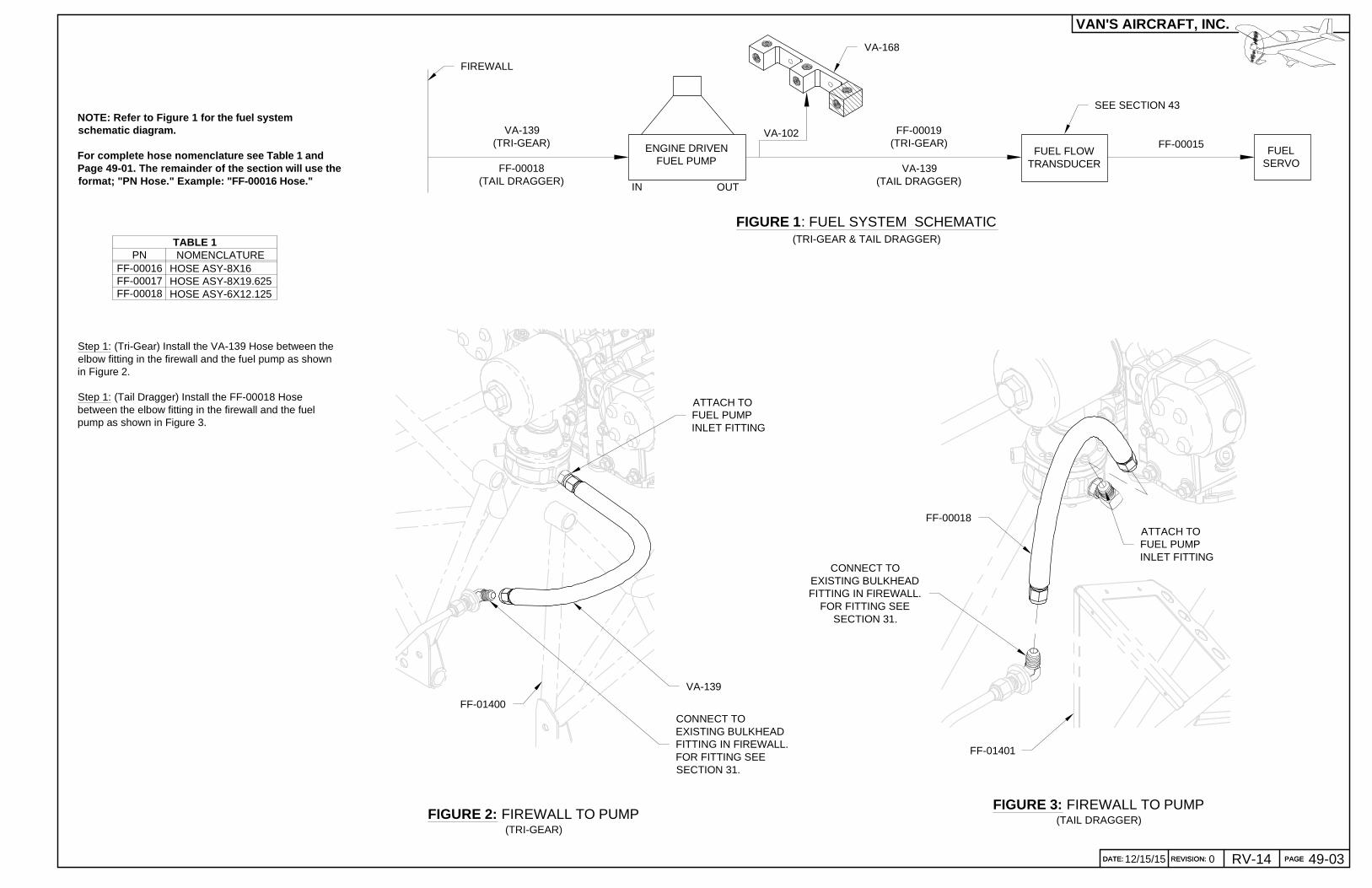
FIGURE 2: FIREWALL TO PUMP(TRI-GEAR)
NOTE: Refer to Figure 1 for the fuel systemschematic diagram.
For complete hose nomenclature see Table 1 andPage 49-01. The remainder of the section will use t heformat; "PN Hose." Example: "FF-00016 Hose."
FIGURE 1: FUEL SYSTEM SCHEMATIC(TRI-GEAR & TAIL DRAGGER)
IN OUT
ENGINE DRIVENFUEL PUMP
FUEL FLOWTRANSDUCER
FUELSERVO
VA-139(TRI-GEAR)
FF-00018(TAIL DRAGGER)
FF-00015VA-102 FF-00019
(TRI-GEAR)
VA-139(TAIL DRAGGER)
VA-139
ATTACH TOFUEL PUMPINLET FITTING
FIREWALL
VA-168
CONNECT TOEXISTING BULKHEADFITTING IN FIREWALL.FOR FITTING SEESECTION 31.
FF-01400
FIGURE 3: FIREWALL TO PUMP(TAIL DRAGGER)
FF-01401
FF-00018
CONNECT TOEXISTING BULKHEADFITTING IN FIREWALL.
FOR FITTING SEESECTION 31.
Step 1: (Tri-Gear) Install the VA-139 Hose between theelbow fitting in the firewall and the fuel pump as shownin Figure 2.
Step 1: (Tail Dragger) Install the FF-00018 Hosebetween the elbow fitting in the firewall and the fuelpump as shown in Figure 3.
ATTACH TOFUEL PUMPINLET FITTING
HOSE ASY-8X16HOSE ASY-8X19.625HOSE ASY-6X12.125
FF-00016FF-00017FF-00018
PN NOMENCLATURETABLE 1
SEE SECTION 43
PAGEREVISION:DATE:
VAN'S AIRCRAFT, INC.
DATE: REVISION: PAGE 49-03012/15/15 RV-14
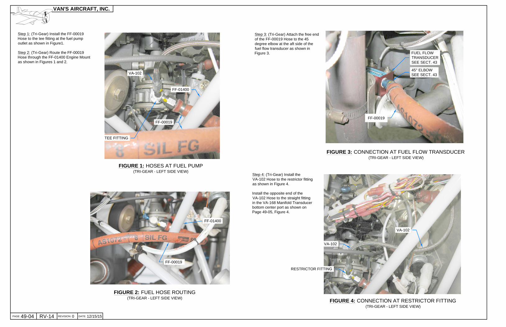
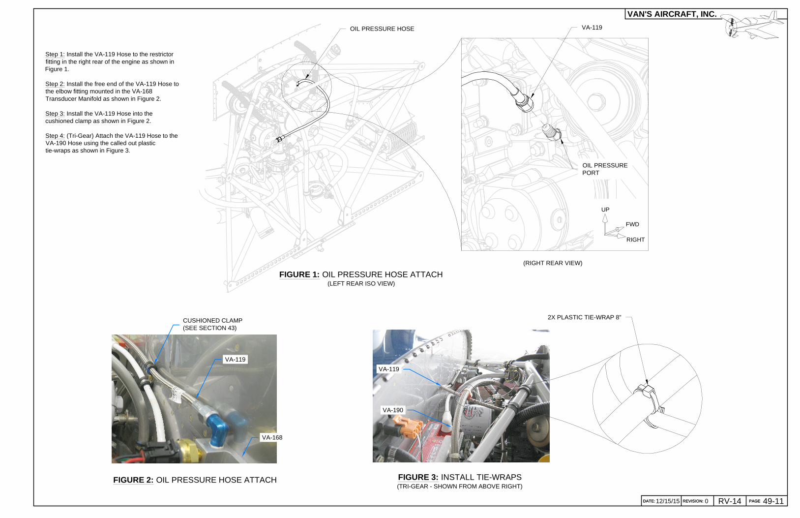
Step 1: (Tri-Gear) Install the FF-00019Hose to the tee fitting at the fuel pumpoutlet as shown in Figure1.
Step 2: (Tri-Gear) Route the FF-00019Hose through the FF-01400 Engine Mountas shown in Figures 1 and 2.
FIGURE 1: HOSES AT FUEL PUMP(TRI-GEAR - LEFT SIDE VIEW)
FF-00019
VA-102
FIGURE 2: FUEL HOSE ROUTING(TRI-GEAR - LEFT SIDE VIEW)
FF-00019
Step 3: (Tri-Gear) Attach the free endof the FF-00019 Hose to the 45degree elbow at the aft side of thefuel flow transducer as shown inFigure 3.
RESTRICTOR FITTING
FIGURE 3: CONNECTION AT FUEL FLOW TRANSDUCER(TRI-GEAR - LEFT SIDE VIEW)
FF-01400
FF-01400
Step 4: (Tri-Gear) Install theVA-102 Hose to the restrictor fittingas shown in Figure 4.
Install the opposite end of theVA-102 Hose to the straight fittingin the VA-168 Manifold Transducerbottom center port as shown onPage 49-05, Figure 4.
FIGURE 4: CONNECTION AT RESTRICTOR FITTING(TRI-GEAR - LEFT SIDE VIEW)
VA-102
VA-102
FF-00019
45° ELBOWSEE SECT. 43
FUEL FLOWTRANSDUCERSEE SECT. 43
TEE FITTING
PAGE REVISION: DATE:
VAN'S AIRCRAFT, INC.
49-04 RV-14 0 12/15/15
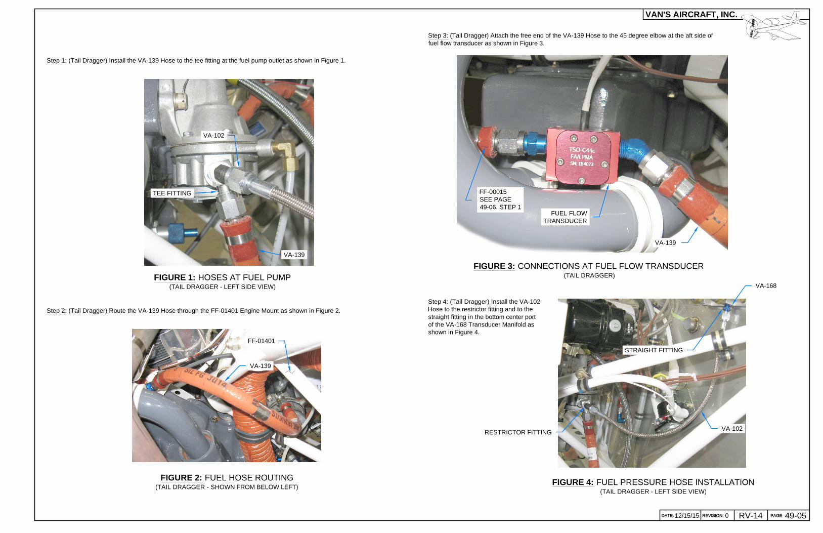
VA-102
VA-139
FIGURE 1: HOSES AT FUEL PUMP(TAIL DRAGGER - LEFT SIDE VIEW)
Step 1: (Tail Dragger) Install the VA-139 Hose to the tee fitting at the fuel pump outlet as shown in Figure 1.
Step 3: (Tail Dragger) Attach the free end of the VA-139 Hose to the 45 degree elbow at the aft side offuel flow transducer as shown in Figure 3.
Step 2: (Tail Dragger) Route the VA-139 Hose through the FF-01401 Engine Mount as shown in Figure 2.
FUEL FLOWTRANSDUCER
FIGURE 3: CONNECTIONS AT FUEL FLOW TRANSDUCER(TAIL DRAGGER)
VA-139
FF-00015SEE PAGE49-06, STEP 1
TEE FITTING
VA-139
FF-01401
Step 4: (Tail Dragger) Install the VA-102Hose to the restrictor fitting and to thestraight fitting in the bottom center portof the VA-168 Transducer Manifold asshown in Figure 4.
FIGURE 4: FUEL PRESSURE HOSE INSTALLATION(TAIL DRAGGER - LEFT SIDE VIEW)
VA-102
VA-168
RESTRICTOR FITTING
STRAIGHT FITTING
PAGEREVISION:DATE:
VAN'S AIRCRAFT, INC.
DATE: REVISION: PAGERV-1412/15/15 0 49-05
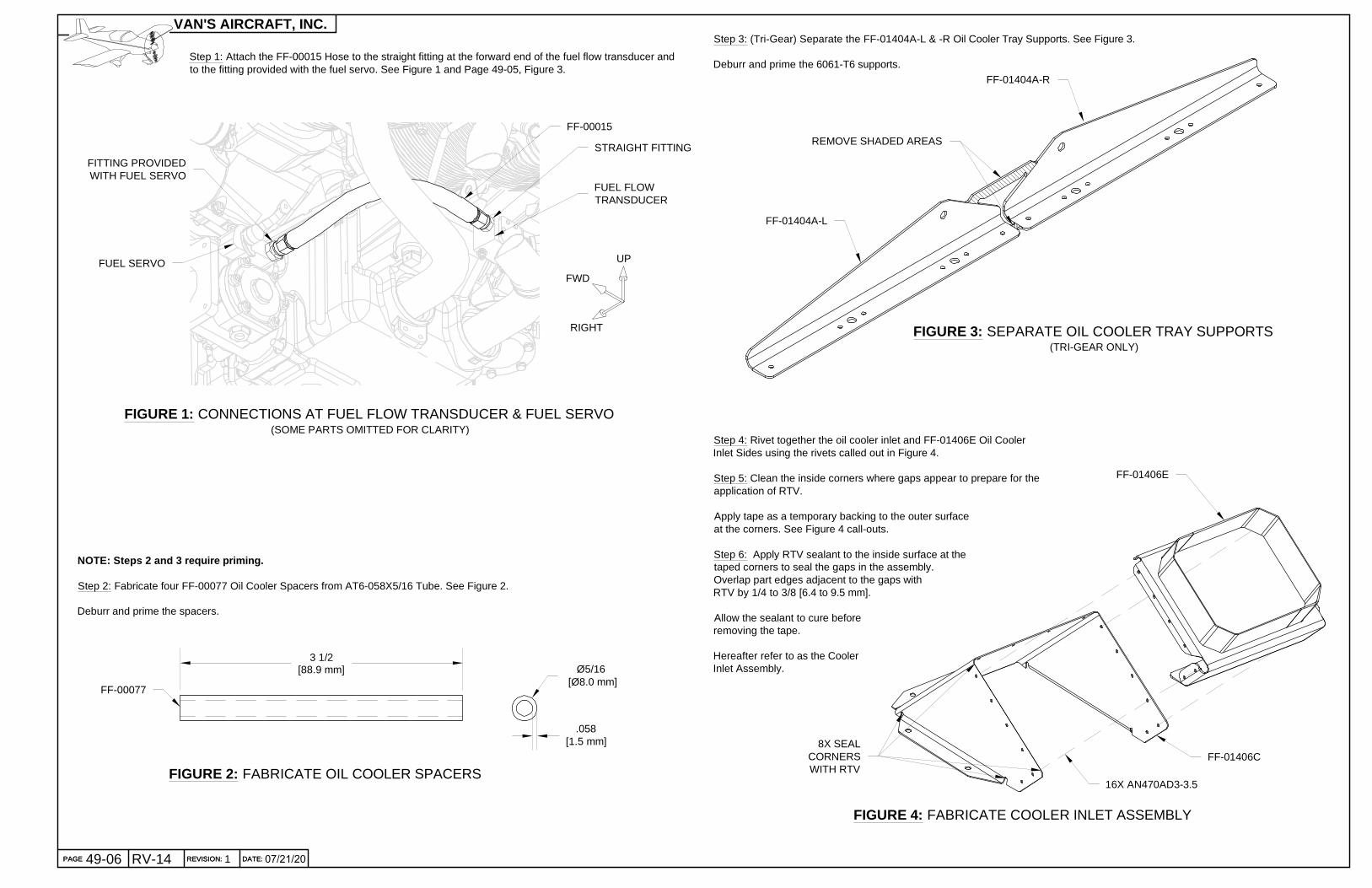
NOTE: Steps 2 and 3 require priming.
Step 2: Fabricate four FF-00077 Oil Cooler Spacers from AT6-058X5/16 Tube. See Figure 2.
Deburr and prime the spacers.
FIGURE 2: FABRICATE OIL COOLER SPACERS
Ø5/16 [Ø8.0 mm]
Step 1: Attach the FF-00015 Hose to the straight fitting at the forward end of the fuel flow transducer andto the fitting provided with the fuel servo. See Figure 1 and Page 49-05, Figure 3.
FIGURE 1: CONNECTIONS AT FUEL FLOW TRANSDUCER & FUEL SERVO(SOME PARTS OMITTED FOR CLARITY)
UP
FWD
RIGHT
FF-00015
FITTING PROVIDEDWITH FUEL SERVO
STRAIGHT FITTING
FUEL SERVO
FUEL FLOWTRANSDUCER
FF-00077
.058[1.5 mm]
FIGURE 4: FABRICATE COOLER INLET ASSEMBLY
16X AN470AD3-3.5
FF-01406C
FF-01406E
Step 4: Rivet together the oil cooler inlet and FF-01406E Oil CoolerInlet Sides using the rivets called out in Figure 4.
Step 5: Clean the inside corners where gaps appear to prepare for theapplication of RTV.
Apply tape as a temporary backing to the outer surfaceat the corners. See Figure 4 call-outs.
Step 6: Apply RTV sealant to the inside surface at thetaped corners to seal the gaps in the assembly.Overlap part edges adjacent to the gaps withRTV by 1/4 to 3/8 [6.4 to 9.5 mm].
Allow the sealant to cure beforeremoving the tape.
Hereafter refer to as the CoolerInlet Assembly.
FIGURE 3: SEPARATE OIL COOLER TRAY SUPPORTS(TRI-GEAR ONLY)
FF-01404A-L
FF-01404A-R
REMOVE SHADED AREAS
Step 3: (Tri-Gear) Separate the FF-01404A-L & -R Oil Cooler Tray Supports. See Figure 3.
NOTE: Refer to Section 5.27 Fluid Fittings for thr ead sealant recommendations and installation tips. Use of a back-upwrench on the oil cooler's hex bosses is recommende d. The 'top' side is defined by the fluid fitting o rientation since theoil cooler is symmetrical.
Step 1: (Tri-Gear) Install the two elbow fittings into the EA-00002 Oil Cooler 2006X as shown in Figure 1.
ANGLE MEASURED FROM FITTING'SFLAT WRENCHING SURFACE. TYP.
Step 3: Clean the oil cooler and P seal surfaces to bejoined.
Spread a layer of clear silicone adhesive/sealant (not RTV)on the called-out horizontal fins which are on the 'top' sideof the EA-00002 Oil Cooler 2006X. See Figure 4. SeeFigures 1 and 2 for reference to the 'top' side.
Rotate the oil cooler 90° as shown in Figure 5.
Step 4: Run a continuous bead of the clear siliconeadhesive/sealant across the ends of the fins per the Figure5 call-out. (The object here being to seal the ends and forceall the air to pass through the cooler's fins.)
Step 5: Install one FF-00079 P Seal to the oil cooler asshown in Figure 5. Center the seal along the width of the oilcooler. Allow the adhesive to cure before continuing.
Repeat Steps 3 thru 5 to install a P seal at the oil cooler'sopposite end.
2X APPROX.1/4 [6.4 mm] BEAD
OF ADHESIVE
2X ADHESIVE LAYERON HORIZONTAL FINS
Step 2: Fabricate two FF-00079 P Seals from SEAL-00008 by cutting tothe length shown in Figure 3.
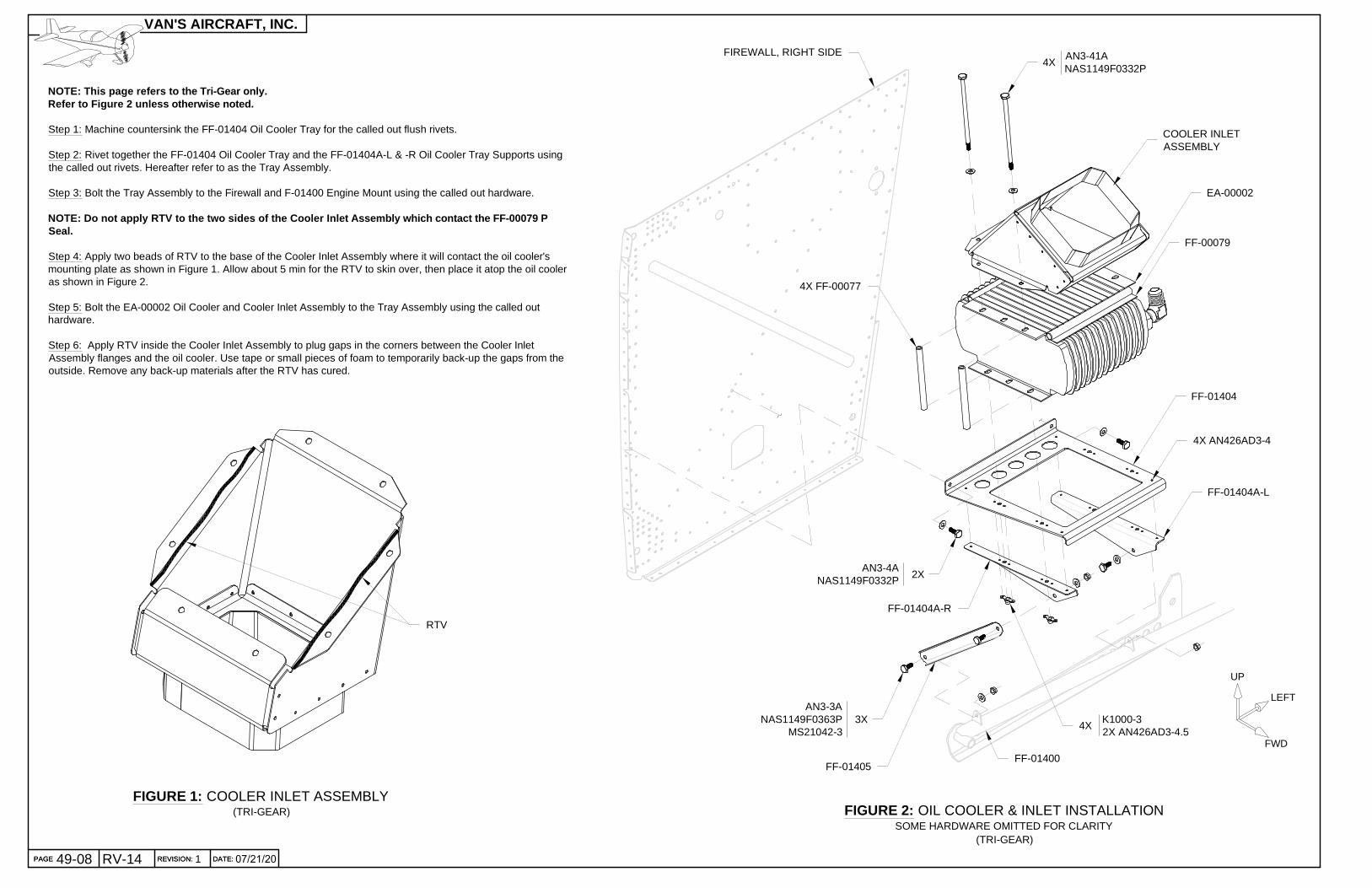
NOTE: This page refers to the Tri-Gear only.Refer to Figure 2 unless otherwise noted.
Step 1: Machine countersink the FF-01404 Oil Cooler Tray for the called out flush rivets.
Step 2: Rivet together the FF-01404 Oil Cooler Tray and the FF-01404A-L & -R Oil Cooler Tray Supports usingthe called out rivets. Hereafter refer to as the Tray Assembly.
Step 3: Bolt the Tray Assembly to the Firewall and F-01400 Engine Mount using the called out hardware.
NOTE: Do not apply RTV to the two sides of the Cooler Inlet Assembly which contact the FF-00079 PSeal.
Step 4: Apply two beads of RTV to the base of the Cooler Inlet Assembly where it will contact the oil cooler'smounting plate as shown in Figure 1. Allow about 5 min for the RTV to skin over, then place it atop the oil cooleras shown in Figure 2.
Step 5: Bolt the EA-00002 Oil Cooler and Cooler Inlet Assembly to the Tray Assembly using the called outhardware.
Step 6: Apply RTV inside the Cooler Inlet Assembly to plug gaps in the corners between the Cooler InletAssembly flanges and the oil cooler. Use tape or small pieces of foam to temporarily back-up the gaps from theoutside. Remove any back-up materials after the RTV has cured.
AN3-41ANAS1149F0332P
K1000-32X AN426AD3-4.5
AN3-3ANAS1149F0363P
MS21042-33X
AN3-4ANAS1149F0332P
2X
4X
4X
FF-01404A-L
FF-01404A-R
FF-01405
FF-01404
COOLER INLETASSEMBLY
4X FF-00077
FIREWALL, RIGHT SIDE
FF-01400
EA-00002
4X AN426AD3-4
UP
LEFT
FWD
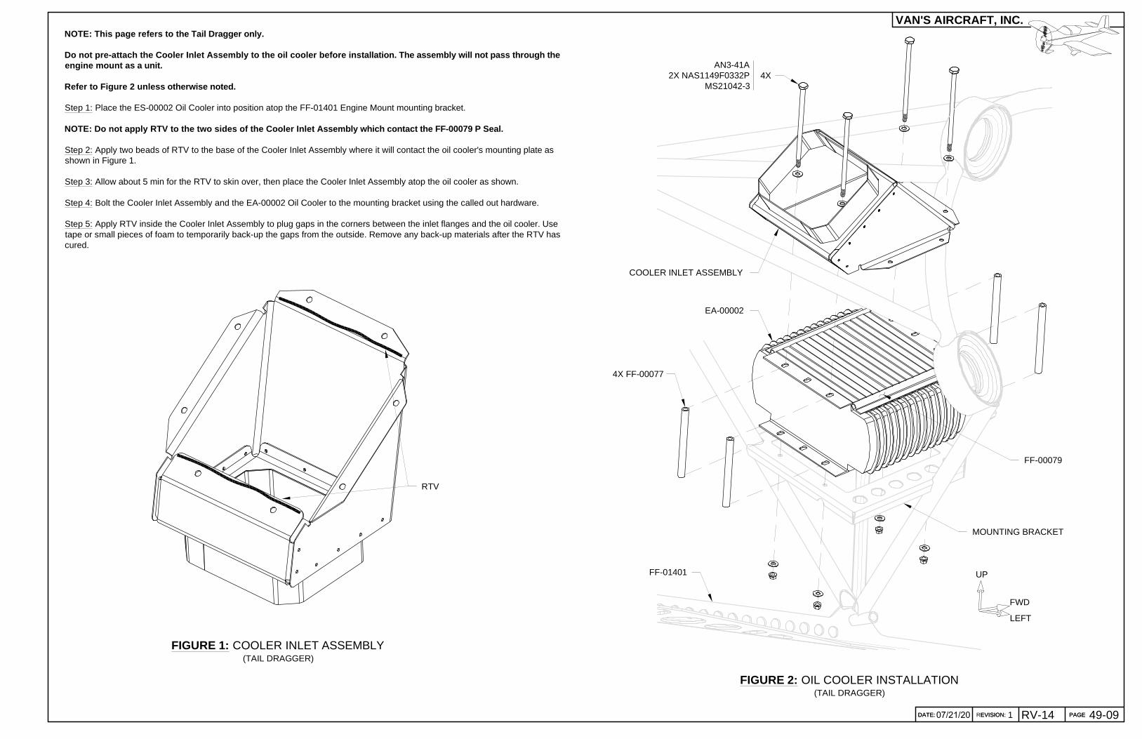
FIGURE 1: COOLER INLET ASSEMBLY(TRI-GEAR)
RTV
FF-00079
PAGE REVISION: DATE:
VAN'S AIRCRAFT, INC.
PAGE REVISION: DATE: 07/21/20RV-14 149-08
EA-00002
FIGURE 2: OIL COOLER INSTALLATION(TAIL DRAGGER)
FF-01401
NOTE: This page refers to the Tail Dragger only.
Do not pre-attach the Cooler Inlet Assembly to the oil cooler before installation. The assembly will not pass through theengine mount as a unit.
Refer to Figure 2 unless otherwise noted.
Step 1: Place the ES-00002 Oil Cooler into position atop the FF-01401 Engine Mount mounting bracket.
NOTE: Do not apply RTV to the two sides of the Cooler Inlet Assembly which contact the FF-00079 P Seal.
Step 2: Apply two beads of RTV to the base of the Cooler Inlet Assembly where it will contact the oil cooler's mounting plate asshown in Figure 1.
Step 3: Allow about 5 min for the RTV to skin over, then place the Cooler Inlet Assembly atop the oil cooler as shown.
Step 4: Bolt the Cooler Inlet Assembly and the EA-00002 Oil Cooler to the mounting bracket using the called out hardware.
Step 5: Apply RTV inside the Cooler Inlet Assembly to plug gaps in the corners between the inlet flanges and the oil cooler. Usetape or small pieces of foam to temporarily back-up the gaps from the outside. Remove any back-up materials after the RTV hascured.
FIGURE 4: AT OIL COOLER AFT FITTING(TAIL DRAGGER - SHOWN FROM BELOW LEFT)
FF-00016
FF-00016
FF-00016
UPPER OIL PORT
PAGE REVISION: DATE:
VAN'S AIRCRAFT, INC.
PAGE REVISION: DATE: 12/15/15RV-14 049-12
APPLY RTV BETWEENHOSE AND FIREWALLIF/AS REQUIRED.
FIGURE 1: OVERVIEW
FF-00016
UPPER OIL PORT
UP
FWD
LEFT
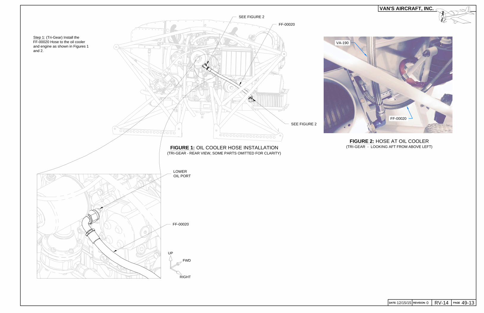
Step 1: (Tri-Gear) Install theFF-00020 Hose to the oil coolerand engine as shown in Figures 1and 2.
FF-00020
FF-00020
UP
FWD
RIGHT
VA-190
LOWEROIL PORT
FIGURE 1: OIL COOLER HOSE INSTALLATION(TRI-GEAR - REAR VIEW, SOME PARTS OMITTED FOR CLARITY)
FIGURE 2: HOSE AT OIL COOLER(TRI-GEAR - LOOKING AFT FROM ABOVE LEFT)
SEE FIGURE 2
SEE FIGURE 2
PAGEREVISION:DATE:
VAN'S AIRCRAFT, INC.
DATE: REVISION: PAGE 49-13RV-1412/15/15 0
FF-00020
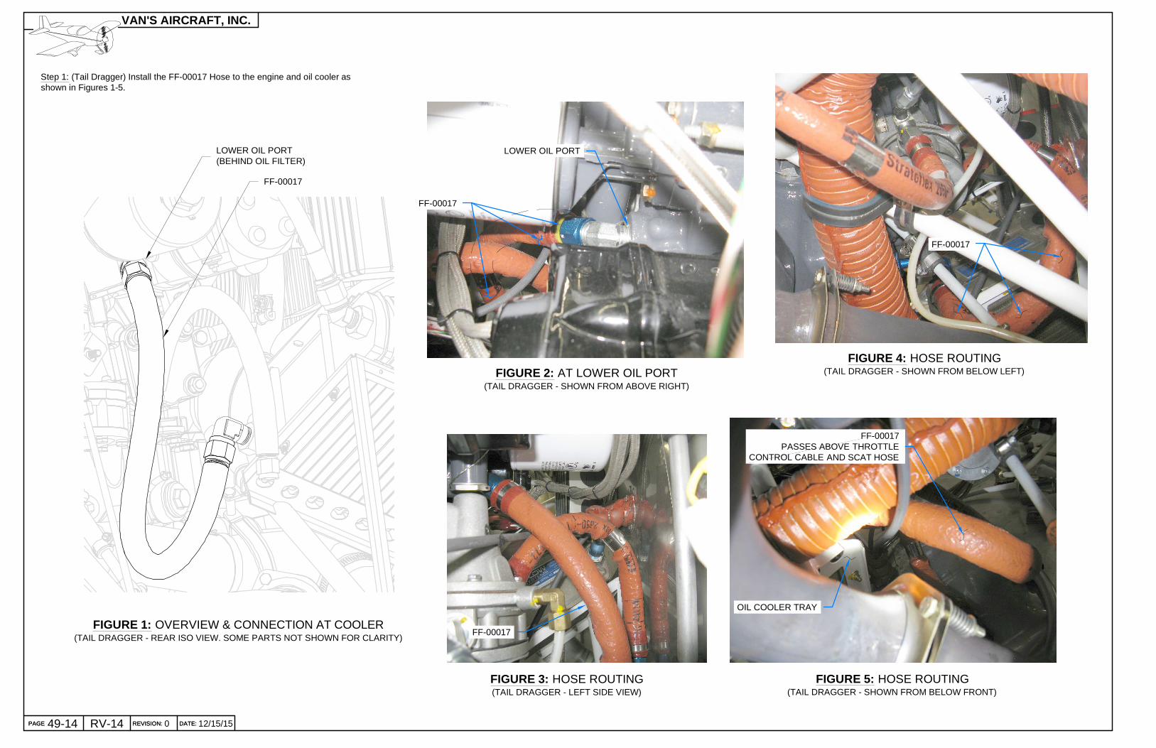
Step 1: (Tail Dragger) Install the FF-00017 Hose to the engine and oil cooler asshown in Figures 1-5.
FIGURE 2: AT LOWER OIL PORT(TAIL DRAGGER - SHOWN FROM ABOVE RIGHT)
FIGURE 3: HOSE ROUTING(TAIL DRAGGER - LEFT SIDE VIEW)
FF-00017
FIGURE 5: HOSE ROUTING(TAIL DRAGGER - SHOWN FROM BELOW FRONT)
FIGURE 4: HOSE ROUTING(TAIL DRAGGER - SHOWN FROM BELOW LEFT)
FF-00017
OIL COOLER TRAY
FF-00017
FF-00017PASSES ABOVE THROTTLE
CONTROL CABLE AND SCAT HOSE
LOWER OIL PORT
FIGURE 1: OVERVIEW & CONNECTION AT COOLER(TAIL DRAGGER - REAR ISO VIEW. SOME PARTS NOT SHOWN FOR CLARITY)
PAGE REVISION: DATE:
VAN'S AIRCRAFT, INC.
PAGE REVISION: DATE: 12/15/1549-14 RV-14 0
LOWER OIL PORT(BEHIND OIL FILTER)
FF-00017
NOTE: Refer to Section 48 for scat hose/duct preparationinstructions.
Step 1: Add a stabilizing bead of RTV to the VENT SCAT 5X21and allow to cure.
Step 2: Pre-form one of the HW-00022 clamps to approximatethe shape of the Cooler Inlet Assembly flange.
Step 3: (Tail Dragger) Slide the two hose clamps called out inFigure 2 onto the VENT SCAT 5X21 Scat Duct.
Slide the scat duct onto the Cooler Inlet Assembly andCB-00037 5" Flanged Duct flanges as shown in Figure 2.
Step 3: (Tri-Gear) Fabricate FF-01416 5" Scat Duct from VENTSCAT 5X21 by cutting to the dimension shown in Figure 1.
Slide the two hose clamps onto the scat duct.
Slide the scat duct onto the Cooler Inlet Assembly andCB-00037 5" Flanged Duct flanges as shown in Figure 3.
Step 4: Slide the lower hose clamp into position and tighten perFigure 2 or 3.
Step 5: Eliminate contact between the engine mount and scatduct, if necessary, by twisting the scat duct along its length untilthere is at least 1/4 in. [6.4 mm] of clearance.
Eliminate contact between the engine dipstick and scat duct, ifnecessary, by adjusting the scat duct fit at the CB-00037.
Tighten the upper hose clamp.
Step 6: Add RTV to contacting surfaces such as the manifoldpressure hose (if applicable).
FIGURE 3: CONNECT SCAT DUCT(TRI-GEAR - RIGHT SIDE VIEW)
COOLER INLETASSEMBLY
VENT SCAT 5X21
COOLER INLETASSEMBLY
FIGURE 2: CONNECT SCAT DUCT(TAIL DRAGGER - RIGHT SIDE VIEW)
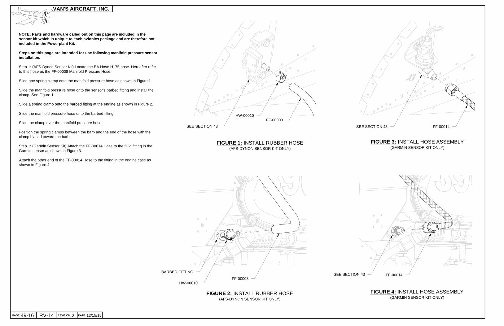
NOTE: Parts and hardware called out on this page ar e included in thesensor kit which is unique to each avionics package and are therefore notincluded in the Powerplant Kit.
Steps on this page are intended for use following m anifold pressure sensorinstallation.
Step 1: (AFS-Dynon Sensor Kit) Locate the EA Hose H175 hose. Hereafter referto this hose as the FF-00008 Manifold Pressure Hose.
Slide one spring clamp onto the manifold pressure hose as shown in Figure 1.
Slide the manifold pressure hose onto the sensor's barbed fitting and install theclamp. See Figure 1.
Slide a spring clamp onto the barbed fitting at the engine as shown in Figure 2.
Slide the manifold pressure hose onto the barbed fitting.
Slide the clamp over the manifold pressure hose.
Position the spring clamps between the barb and the end of the hose with theclamp biased toward the barb.
Step 1: (Garmin Sensor Kit) Attach the FF-00014 Hose to the fluid fitting in theGarmin sensor as shown in Figure 3.
Attach the other end of the FF-00014 Hose to the fitting in the engine case asshown in Figure 4.